metal seated ball valves - nibsco...
TRANSCRIPT

M-CLASSMetal seated ball valves

One year guarantee or extended guarantee options for special applications
A Cut Above
Flanged, socket weld, butt weld, threaded and non-standard end connections
Lockable tee-handle gearbox and actuated options
Dual live loaded packing sets eliminate stem leaks
Blow-out proof stem design ensures safety
Pressures up to 4500# class
Ball and seats have the most advanced coating/surface hardening technology
options available to provide the best solution for critical applications
Metal ball and seats are lap matched to provide bubble-tight shut-off
• 1/2” TO 16” standard port
• 150# up to 4500#
• -270°C (-454°F) TO 843°C (1550°F)

Oversized stem to prevent twisting
Extended bonnet for insulation
Optional arcuate cut ball for abrasive or high velocity applications
Optional scalloped seat to prevent build-up of material between the seat and the spring
Available in all commercially available materials (Hastelloy, Alloy 20, Titanium, Duplex, Monel, Zirconium, etc.)
Tripod mounting bracket with ISO 5211 option for simple and precise actuator mounting
Live loaded body and bonnet bolts compensate for thermal expansion, pressure fluctuations and vibration
Live loaded seats compensate for thermal and pressure variances, ensuring the best possible seal, even at low pressures
• Bi-directional seating to handle back
pressures to the full pressure rating
of the valve

ON/OFF VALVEThe On/Off Ball Valve is an elite, made-to-order, metal seated ball valve, unparalleled
in quality and performance.
They are designed for any combination of abrasive, corrosive, high temperature, high pressure, and high-cycle applications. Options include Vari-V and arcuate cut balls, exotic alloys, and scalloped seats. Not only do M-Class Ball Valves provide superior performance for the toughest applications, they are truly bi-
directional and provide bubble-tight shut-off.

ON/OFF VALVE

Our Cryogenic Valves are designed to withstand temperatures of -270°C/ -454°F and have a minimum 12” bonnet extension to protect the actuator and handle from ice build-up. The valve features the patented M-Class Stem Sealing System, a detachable bonnet, and metal seats. M-Class Cryogenic Valves feature a drilled ball, to relieve pressure, and a fully grounded stem. A bolt-on retrofit kit is also available.
CRYO VALVEThe Cryogenic Valve can handle temperatures as low as -270 °C (-454 °F). A bolt-on retrofit kit is
also available.

CRYO VALVE

BLOCK+BLEEDThe Block+Bleed Valves provide bubble tight shut-off and are offered in single and double Block+Bleed configurations
Gosco's Block+Bleed Valves combine live loaded seat technology, the patented M-Class tripod and stem packing, and completely bi-directional sealing. This configuration makes our Block+Bleed Valves extremely versatile, enabling them
to tackle the toughest severe service applications..

BLOCK+BLEED

The 3-Way Diverter offers superior reliability in a metal-seated package. Configurations include a “Single-L Port” ball for 180° applications, specifically for when there is no mix of the media between the two ports, and a “Double-L Port” ball for 90° applications in which mixing is expected to occur between the ports. Whatever the application, the 3-Way Diverter Valve is guaranteed to outperform its competitors and surpass all expectations.
3-WAY VALVEThe 3-Way Diverter Valve provides bottom entry with flow, to the left ports or right ports,
“Single-L” for 180°, or “Double-L” for 90°.

3-WAY VALVE

The Vari-V Ball Valve offers precise flow control through a specific profile that is
machined into the ball.
VARI-V VALVE
When precise control of flow or pressure is required in a metal seated ball valve, the M-Class Vari-V Control Valve is perfect for your tough applications. Standard 10°, 30°, 60°, 90° V’s are cut in to the ball for a complete range of CV's and control requirements. Custom profile V’s are used for unusual applications requiring special flow characteristics.

VARI-V VALVE

At the heart of every Gosco M-Class control valve is the Vari-V ball. The profile of the V-ball determines the flow characteristic of the valve and can be changed to suit the application. 10°, 30°, 60° and 90° V-balls are the most commonly used, but several other profiles are available. The transition between high flow and fine control with the Vari-V is extremely smooth.
ControlFreak
Linear-V
High Turndown-V
Filler-V
90˚
Linear-V is a slot in the ball that can be machined for precise flow requirements. Filler-V is used when you need maximum flow for filling followed by precise flow to accurately control the levels. High Turndown-V maximizes flow in the open position, and provides fine flow control when the valve is partially closed.

10˚ V-Ball
30˚ V-Ball
60˚ V-Ball
V-Ball
Custom V-balls are available for applications where specific flow requirements can not be met with the standard V-balls. Using Computational Fluid Dynamics (CFD), we can create a V-ball with a specific profile to fit any application. Anti-cavitation trim is also available. For examples of custom V-ball applications, including videos and specifications, visit www.goscovalves.com
FreeSpirit

An arcuate cut is a profile in the ball that reduces velocity both when the valve opens, and as
it closes. When a standard ball valve is in the first and last ten degrees of opening, the gap
between the ball and seat is an elliptical shape. The velocities are very high (especially in the
corners), and erosion occurs. With an arcuate cut, the opening on the ball is close to three
times larger. This reduces the velocity by spreading out the flow through a larger opening,
which ultimately reduces wear on the ball and seats. An arcuate cut ball is best utilized in
abrasive and high cycle applications.
SlowPoke

A common problem with metal seated valves is the build-up of material between the upstream seat and
the body. Our approach to this problem is very different from traditional valve manufacturers. Their valve
designs attempt to prevent media from getting behind the seat by sealing the outer edge and back of
the seat. Our philosophy is the opposite: let the media flow behind the seat, as the seat’s design allows
material to escape just as easily. This is done with angled scallops at the back and outer edge of the seat.
The size, steepness of the angle, and spacing of the scallops vary with the particle sizes and the pressure
inside the valve.
SmoothOperator


The M-CLASS Tripod Mount is designed to eliminate the problems associated with traditional brackets
SimpleNo bracket - only a plate and coupling is needed
Dead CenteredThe mounting plate is secured between the C&C machined tripod prongs and cannot move in any direction. This guarantees perfect alignment of the actuator to the valve.
Easy to Assemble The plate can be mounted on the actuator first, then the actuator will automatically be aligned by the three prongs.
Perfectly FlatThree points define a plane, meaning the actuator will not rock.
Fully Visible The double “D” on the stem is easily seen, giving a constant visual indication of the valve’s position.
Open Between the ProngsAllows full access to the packing adjustment without removal of the actuator.
Insulatable A minimum of 2” between the top of the flange and the tripod allows insulation to be installed without covering the packing adjustments.
TRIPOD MOUNT

Finite Element Analysis (FEA) is used in Gosco Valves’ design process to predict the behavior of
a valve’s components by subjecting them to varying loads. This ensures structural integrity. The
analysis is based on variables such as maximum pressure and temperature inside the valve, and
maximum actuator torque. The illustration shows the stress distribution in a body and bonnet
assembly, based on FEA analysis.
StressReliever
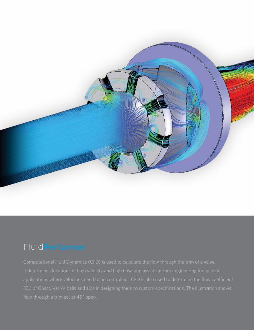
FluidPerformer
Computational Fluid Dynamics (CFD) is used to calculate the flow through the trim of a valve.
It determines locations of high velocity and high flow, and assists in trim engineering for specific
applications where velocities need to be controlled. CFD is also used to determine the flow coefficient
(Cv) of Gosco Vari-V balls and aids in designing them to custom specifications. The illustration shows
flow through a trim set at 45˚ open.

COATINGS
CERAMICSGosco also manufactures trim sets from a variety of different ceramics including a proprietary Alumina/Zirconia based ceramic. This type of ceramic offers the chemical resistance and hardness of an alumina, combined with the toughness of zirconia. It does not shatter on impact and is abrasion and thermal shock resistant.
HardCore
BORONIZINGA thermochemical surface treatment in which Boron atoms are diffused into the surface of a base metal to form borides. It creates a new intermetallic layer with a hardness off the Rockwell C scale. The base metal is chosen to handle the temperature, abrasion and corrosion of the process, and has a superior wear resistance to that of coatings.
High Velocity Oxygen Flame (HVOF) is a thermal spray system that fuses a powdered metal feed (generally Chrome or Tungsten Carbide) onto a base material. In this process the oxygen flame, paired with a number of fuel gases, accelerates and propels the feed stock at supersonic speeds (1800ft/sec or 549 m/sec) directly on to the base material. Temperatures can reach upwards of 2300°C (4172°F). When particles strike the base material, they form a "splat", quickly cooling to create a high density coating.

-20
to 1
00 200
300
400
500
600
700
800
900
1000
1100
1200
-29
to 3
8 93 149
204
260
316
371
427
482
538
593
649
0
250
1250
1750
2000
2500900#600#
300#
150#
500
750
1000
1500
2250Saturated Steam
17
86
121
138
172
34
52
69
103
155
pre
ssu
re (
psi
g)
temperature (˚F)
pre
ssu
re (
bar)
temperature (˚C)
OPERATING INFORMATION 150#, 300#, 600#, 900# M-Class Valves
0
2000
4000
6000
8000
10000
12000
-20
to 1
00 200
300
400
500
600
700
800
900
1000
1100
1200
4500#
2500#
1500#
138
276
414
552
690
827
-29
to 3
8 93 149
204
260
316
371
427
482
538
593
649
pre
ssu
re (
psi
g)
temperature (˚F)
pre
ssu
re (
bar)
temperature (˚C)
OPERATING INFORMATION 1500#, 2500#, 4500# M-Class Valves

Material Ratings
0
200
400
600
800
-29
to 3
8 50 100
150
200
250
300
350
400
450
500
550
600
4500 Class2500 Class1500 Class900 Class600 Class300 Class150 Class
-20
to 1
00 122
212
302
392
482
572
662
752
842
932
1022
1112
2901
5802
8702
11603
F11: A 182 Gr. F11 Cl.2, A 217 Gr. WC6
0
200
400
600
800
-29 t
o 38 50 10
015
020
025
030
035
040
045
050
055
060
0
4500 Class2500 Class1500 Class900 Class600 Class300 Class150 Class
-20 t
o 10
012
221
230
239
248
257
266
275
284
293
210
2211
12
2901
5802
8702
11603
F22: A 182 Gr. F22 CI.3, A 217 Gr. WC9
pre
ssu
re (
psi
g)
pre
ssu
re (
bar)
temperature (˚F)temperature (˚C)
pre
ssu
re (
psi
g)
pre
ssu
re (
bar)
temperature (˚F)temperature (˚C)

0
200
400
600
800
-29
to 3
8 50 100
150
200
250
300
350
400
450
500
550
600
650
4500 Class2500 Class1500 Class900 Class600 Class300 Class150 Class
-20
to 1
00 122
212
302
392
482
572
662
752
842
932
1022
1112
2901
5802
8702
11603
1202
F9: A 182 Gr. F9
pre
ssu
re (
psi
g)
pre
ssu
re (
bar)
temperature (˚F)temperature (˚C)

0
200
400
600
800
-29
to 3
8 50 100
150
200
250
300
Temperature ° C
4500 Class2500 Class1500 Class900 Class600 Class300 Class150 Class
-20
to 1
00 122
212
302
392
482
572
2901
5802
8702
11603
SP & DP: A 182 Gr. F51, A 789 Gr. S32750, A 789 Gr. S32760
0
175
350
525
700
-29
to 3
8 50 100
150
200
250
300
350
400
450
4500 Class2500 Class1500 Class900 Class600 Class300 Class150 Class
-20
to 1
00 122
212
302
392
482
572
662
752
842
2524
5076
7614
10153
SL: A 182 Gr. F316L
Material Ratingsp
ress
ure
(p
sig
)p
ress
ure
(b
ar)
temperature (˚F)temperature (˚C)
pre
ssu
re (
psi
g)
pre
ssu
re (
bar)
temperature (˚F)temperature (˚C)

Temperature (°C )
0
200
400
600
800
-29
to 3
8 50 100
150
200
250
300
350
400
450
500
550
600
650
700
750
800
816
4500 Class2500 Class1500 Class900 Class600 Class300 Class150 Class
-20
to 1
00 122
212
302
392
482
572
662
752
842
932
1022
1112
2901
5802
8702
11603
1202
1292
1382
1472
1501
SS: A 351 Gr. CF8M, A 479 Gr. 316
pre
ssu
re (
psi
g)
pre
ssu
re (
bar)
temperature (˚F)temperature (˚C)

inches, lbs / cm, kgsM-Class ball valve Overall diMensiOns2
Valve Size
A(diameter)
B C D(diameter)
E FG
Weight3
150# 300# 600# 900# 1500# 2500#
1/2” FP 6.50/16.51 0.375/0.95 7.85/19.94 0.50/1.27 4.10/10.41 10.35/26.29 4.25/10.80 5.50/13.97 6.50/16.51 8.00/20.32 9.00/22.86 12.50/31.75 40/18.1
3/4” SP 6.50/16.51 0.375/0.95 7.85/19.94 0.50/1.27 4.10/10.41 10.35/26.29 4.62/11.73 6.00/15.24 7.50/19.05 9.00/22.86 10.00/25.40 12.80/32.51 45/20.4
3/4” FP 8.00/20.32 0.5/1.27 9.18/23.32 0.63/1.60 4.70/11.94 12.28/31.19 4.62/11.73 6.00/15.24 7.50/19.05 9.00/22.86 10.00/25.40 12.80/32.51 70/31.8
1” SP 8.00/20.32 0.5/1.27 9.18/23.32 0.63/1.60 4.70/11.94 12.28/31.19 5.00/12.70 6.50/16.51 8.50/21.59 10.00/25.40 11.50/29.21 13.30/33.78 76/34.5
1” FP 8.00/20.32 0.5/1.27 9.38/23.83 0.63/1.60 4.70/11.94 12.48/31.70 5.00/12.70 6.50/16.51 8.50/21.59 10.00/25.40 11.50/29.21 15.00/38.10 82/37.2
1 1/4” SP 8.00/20.32 0.5/1.27 9.38/23.83 0.63/1.60 4.70/11.94 12.48/31.70 5.50/13.97 7.00/17.78 9.00/22.86 11.00/27.94 12.50/31.75 15.50/39.37 85/38.6
1 1/4” FP 11.00/27.94 0.75/1.90 13.23/33.60 0.88/2.24 6.30/16.00 17.48/44.40 5.50/13.97 7.00/17.78 9.00/22.86 11.00/27.94 12.50/31.75 16.50/41.91 160/72.6
1 1/2” SP 11.00/27.94 0.75/1.90 13.23/33.60 0.88/2.24 6.30/16.00 17.48/44.40 6.50/16.51 7.50/19.05 9.50/24.13 12.00/30.48 13.50/34.29 17.00/43.18 173/78.5
1 1/2” FP 11.00/27.94 0.75/1.90 13.93/35.38 0.88/2.24 6.30/16.00 18.18/46.18 6.50/16.51 7.50/19.05 9.50/24.13 12.00/30.48 13.50/34.29 17.60/44.70 170/77.1
2” SP 11.00/27.94 0.75/1.90 13.93/35.38 0.88/2.24 6.30/16.00 18.18/46.18 7.00/17.78 8.50/21.59 11.50/29.21 14.50/36.83 14.50/36.83 17.75/45.09 196/88.9
2” FP 12.20/30.99 0.75/1.90 13.93/35.38 1.00/2.54 5.92/15.04 18.68/47.45 7.00/17.78 8.50/21.59 11.50/29.21 14.50/36.83 14.50/36.83 17.75/45.09 220/99.8
2 1/2” SP 12.20/30.99 0.75/1.90 13.93/35.38 1.00/2.54 5.92/15.04 18.68/47.45 7.50/19.05 9.50/24.13 13.00/33.02 16.50/41.91 16.50/41.91 20.00/50.80 250/113.4
2 1/2” FP 14.50/36.83 1.00/2.54 15.95/40.51 1.25/3.18 6.01/15.27 21.35/54.23 7.50/19.05 9.50/24.13 13.00/33.02 16.50/41.91 16.50/41.91 20.00/50.80 375/170.1
3” SP 14.50/36.83 1.25/3.17 15.95/40.51 1.25/3.18 6.01/15.27 21.35/54.23 8.00/20.32 11.13/28.27 14.00/35.56 15.00/38.10 18.50/46.99 22.75/57.79 405/183.7
3” FP 14.50/36.83 1.25/3.17 16.18/41.10 1.50/3.81 6.01/15.27 21.48/54.56 8.00/20.32 11.13/28.27 14.00/35.56 15.00/38.10 18.50/46.99 22.75/57.79 395/179.2
4” SP 14.50/36.83 1.25/3.17 16.18/41.10 1.50/3.81 6.01/15.27 21.48/54.56 9.00/22.86 12.00/30.48 17.00/43.18 18.00/45.72 21.50/54.61 26.50/67.31 445/201.8
4” FP 16.00/40.64 1.25/3.17 20.00/50.80 1.75/4.45 9.50/24.13 26.60/67.56 9.00/22.86 12.00/30.48 17.00/43.18 18.00/45.72 21.50/54.61 26.50/67.31 675/306.2
6” SP 16.00/40.64 1.25/3.17 20.00/50.80 1.75/4.45 9.50/24.13 26.60/67.56 15.50/39.37 15.88/40.34 22.00/55.88 24.00/60.96 27.75/70.49 36.00/91.44 910/412.8
6” FP 20.00/50.80 2.00/5.08 26.60/67.56 2.50/6.35 11.84/30.07 36.35/92.33 15.50/39.37 15.88/40.34 22.00/55.88 24.00/60.96 27.75/70.49 36.00/91.44 1730/784.7
8” SP 20.00/50.80 2.00/5.08 26.60/67.56 2.50/6.35 11.84/30.07 36.35/92.33 18.00/45.72 19.75/50.17 26.00/66.04 29.00/73.66 32.75/83.19 40.25/102.2 1960/889.0
8” FP4 24.00/60.96 2.25/5.71 35.46/90.07 3.00/7.62 14.90/37.85 48.21/122.5 18.00/45.72 19.75/50.17 26.00/66.04 29.00/73.66 • • 3200/1451
8” FP5 28.00/71.12 2.25/5.71 39.75/100.0 3.50/8.89 16.30/41.40 53.50/135.9 • • • • 32.75/83.19 40.25/102.2 4200/1905
10” SP4 24.00/60.96 2.25/5.71 35.46/90.07 3.00/7.62 14.90/37.85 48.21/122.5 21.00/53.34 22.38/56.85 31.00/78.74 33.00/83.82 • • 3400/1542
10” SP5 28.00/71.12 2.25/5.71 39.75/100.0 3.50/8.89 16.30/41.40 53.50/135.9 • • • • 39.00/99.06 50.00/127.0 4700/2132
For valve sizes larger than 10”, please contact Gosco Valves for dimensional information.
1) Mounting dimensions can be changed to suit custom actuator configurations2) Please visit www.mclassvalve.com to download up-to-date dimensions and sizes3) Except 8” and 10SP”, weights are based on 1500# class valves (contact Gosco Valves)4) Dimensions are for 150#, 300#, 600# and 900# class valves5) Dimensions are for 1500# and 2500# class valves6) NPT Ends also available, contact Gosco Valves for dimensions7) Dimensions are approximate
Weights and dimensions are maximum numbers

M-Class COntrOl ball valve v-ball Cv’s
Valve Size Vari-V 100% 90% 80% 70% 60% 50% 40% 30% 20% 10% Non Vari-V ball Cv’s
1/2” FP
10˚30˚60˚90˚
2.955.76
10.1315.28
2.363.996.939.83
1.943.154.566.29
1.532.223.184.10
1.191.462.022.57
0.840.891.321.58
0.510.510.730.84
0.130.140.150.16
0.000.020.030.03
0.000.000.000.00
23
3/4” SP
10˚30˚60˚90˚
3.014.968.16
11.18
2.223.625.847.73
1.842.894.545.57
1.312.133.003.87
1.011.451.822.39
0.710.831.181.36
0.490.530.670.83
0.000.040.040.04
0.000.000.000.00
15
3/4” FP
10˚30˚60˚90˚
4.278.43
16.8427.63
3.556.45
11.0917.52
2.704.887.59
11.28
2.133.515.126.70
1.552.183.174.14
1.191.492.092.47
0.660.790.951.29
0.370.380.410.46
0.030.030.030.03
0.000.000.000.00
45
1” SP
10˚30˚60˚90˚
4.037.63
15.8219.37
3.295.93
10.8013.37
2.484.597.479.17
2.023.304.746.28
1.502.383.184.07
0.981.331.962.47
0.580.720.951.44
0.340.350.360.60
0.010.010.010.02
0.000.000.000.00
30
1” FP
10˚30˚60˚90˚
5.8812.3426.9140.62
4.979.86
17.3726.78
4.257.50
12.4717.96
3.285.368.19
11.74
2.143.895.457.48
1.742.413.454.49
1.061.632.162.55
0.840.950.971.09
0.220.240.260.28
0.000.000.000.00
77
1 1/4” SP
10˚30˚60˚90˚
5.7410.7523.3037.20
5.099.40
15.5926.09
4.106.63
11.0317.26
3.135.048.11
10.44
2.323.555.046.91
1.592.303.204.37
1.091.541.962.38
0.660.680.951.04
0.210.230.240.26
0.000.000.000.00
46
1 1/4” FP
10˚30˚60˚90˚
10.2420.1039.2670.96
6.8716.0927.2544.32
6.8612.1719.3629.44
5.228.66
13.1118.79
3.736.098.82
11.83
2.864.225.607.44
2.232.553.254.51
1.191.671.752.32
0.520.560.560.75
0.000.000.000.00
126
1 1/2” SP
10˚30˚60˚90˚
9.9020.1337.0966.22
8.0215.8927.3843.48
6.7212.1219.0128.48
5.038.88
13.5618.44
4.426.589.17
12.28
3.224.506.108.08
1.902.383.454.51
0.781.001.241.68
0.360.260.280.35
0.000.000.000.00
82
1 1/2” FP
10˚30˚60˚90˚
12.7628.6055.7396.99
11.0622.3540.1662.87
7.6515.2326.5438.90
5.9411.3817.5324.95
5.218.30
11.8715.69
3.505.487.319.73
2.412.463.075.46
0.891.371.592.37
0.000.460.340.62
0.000.000.000.00
192
2” SP
10˚30˚60˚90˚
13.4127.1549.5680.14
10.2220.9235.8152.63
8.1215.3624.7735.60
5.9811.5417.2023.75
4.747.25
10.8814.43
3.884.907.219.03
2.433.434.105.42
1.281.371.712.07
0.000.410.370.00
0.000.000.000.00
120
2” FP
10˚30˚60˚90˚
21.5347.4792.06
173.40
16.9837.4669.69
110.49
16.0127.3249.0873.44
12.4720.7531.9248.50
10.0714.1221.3629.56
5.269.65
13.9818.56
4.436.538.52
11.54
2.373.054.215.13
0.791.151.311.44
0.000.000.000.00
358
2 1/2” SP
10˚30˚60˚90˚
18.6341.7483.22
139.40
14.8233.5860.0489.84
12.2826.1644.3561.63
8.9818.5229.9841.32
7.0013.6020.4127.57
5.018.59
12.5617.68
3.094.717.339.76
1.972.563.715.27
0.490.530.650.99
0.000.000.000.00
240
2 1/2” FP
10˚30˚60˚90˚
35.1679.21
150.59253.06
29.3563.94
107.54180.69
24.6049.2280.65
119.78
19.6834.3252.9384.32
14.7025.2434.8950.76
10.6315.9022.7232.69
7.639.98
14.8721.11
3.854.986.44
11.67
1.322.162.021.79
0.000.000.000.00
611
3” SP
10˚30˚60˚90˚
34.9373.79
138.23240.46
23.8856.60
101.69154.55
19.8943.6774.53
114.28
16.2533.4251.9473.22
13.5622.8734.9447.24
10.5215.2421.5531.57
7.6010.2213.9817.96
3.996.827.69
10.50
2.182.472.144.49
0.710.690.540.21
350
3” FP
10˚30˚60˚90˚
47.02105.15190.26388.90
32.6580.57
136.08235.03
26.3458.10
112.14157.48
19.8442.9082.2299.49
15.8929.9654.1064.78
12.2719.58
27.638.4
7.9712.1415.80
22.2
3.985.04
13.5411.64
1.811.96
11.063.53
0.000.000.000.00
858
4” SP
10˚30˚60˚90˚
44.0795.43
171.46283.27
33.6477.54
139.82208.78
27.1657.24
103.63147.71
21.8542.3468.8698.21
16.3728.9547.1262.96
11.6119.7727.8041.66
8.4613.0516.7925.34
4.826.047.85
10.82
1.662.062.073.15
0.000.000.000.00
607
4” FP
10˚30˚60˚90˚
58.97160.29332.17652.17
52.74131.67243.98401.89
43.58100.78174.60262.88
33.5272.91
118.86170.63
25.9353.7181.15
111.42
18.1635.1051.8073.39
11.1219.4924.7943.49
7.4210.7315.3424.32
3.663.906.487.20
1.651.341.011.38
1512
6” SP
10˚30˚60˚90˚
71.0164.0270.0409.0
58.0129.0213.0329.0
45.095.0
163.0244.0
35.070.0
115.0166.0
26.051.076.0
110.0
20.036.051.072.0
13.022.031.044.0
7.011.015.022.0
3.14.14.87.4
0.000.000.000.00
1055
6” FP
10˚30˚60˚90˚
148.0367.0816.0
1292.0
112.0286.0568.0890.0
91.0205.0414.0581.0
76.0146.0272.0382.0
55.0104.0177.0234.0
40.070.0
110.0145.0
30.047.067.088.0
19.025.034.045.0
7.49.0
10.014.4
0.000.000.000.00
3664
8” SP
10˚30˚60˚90˚
134.0338.0648.0
1106.0
112.0270.0513.0768.0
92.0209.0378.0538.0
86.0159.0260.0360.0
54.5109.0175.0242.0
35.575.0
112.0148.0
28.046.065.082.0
17.024.032.042.0
6.88.7
10.013.0
0.000.000.000.00
2060
8” FP
10˚30˚60˚90˚
297.0757.0
1650.02577.0
255.0566.0
1078.01682.0
195.0404.0724.0
1065.0
165.0294.0490.0664.0
115.0195.0305.0400.0
75.0130.0186.0233.0
49.070.8
100.0125.0
25.030.040.048.0
5.05.55.76.0
0.000.000.000.00
7768
10” SP
10˚30˚60˚90˚
289.0683.0
1334.02176.0
245.0556.0
1014.01518.0
190.0393.0714.0
1022.0
153.0287.0483.0650.0
105.0185.0298.0383.0
70.0125.0182.0222.0
46.072.095.0
121.0
20.028.436.045.0
4.85.35.55.8
0.000.000.000.00
5826
For valve sizes larger than 10”, please contact Gosco Valves for Cv information.
Cv is defined as the flow of water at 70 ˚F in US gallons per minute though a valve with a 1 psi pressure drop.
0.120.130.140.15

Size Port Bore Connection Pressure Type Body Stem Ball Seat Ball Profile Packing Handle Special Direction
01 = 1/2” S = standard 1 = Schedule 40 F = flanged 1 = 150# C = cast SL = 316L I7 = Inconel 718 B7 = Borided Inconel 718 I7B = Inconel 718, borided 10 = 10˚ V-Ball C = PTFE chevron A = actuated DB = drilled ball (upstream side) U = Unidirectional
02 = 3/4” F = full 2 = Schedule 80 S = socket weld 2 = 300# B = bar stock SH = 316H I6 = Inconel 625 B6 = Borided Inconel 625 I6B = Inconel 625, borided 30 = 30˚ V-Ball G = standard graphoil B = bare shaft 3W = 3-way diverter B = Bidirectional
03 = 1” T = true bore 3 = Schedule 160 B = butt weld 3 = 600# F = forging SS = 316 SS S7 = 17-4 Ph I7 = Inconel 718 HCB = Hastelloy C, borided 60 = 60˚ V-Ball Y = cryogenic T = tee handle O2 = oxygen cleaning •
04 = 1 1/4” • 4 = Schedule 5S X = extended BW 4 = 900# O = other CS = Carbon Steel SS = 316 SS I6 = Inconel 625 HBB = Hastelloy B, borided 90 = 90˚ V-Ball • G = gear box SC = scalloped seat •
05 = 1 1/2” • 5 = Schedule 10S R = RTJ 5 = 1500# • F1 = 1 ¼ Chrome SH = 316H SS = 316 SS CER = ceramic LN = linear V-Ball • L = lever S1 = SC + O2 •
06 = 2” • 6 = Schedule 120 N = NPT 6 = 2500# • F2 = 2 ¼ Chrome SL = 316L SH = 316H EGR = encapsulated graphite HT = high turndown V • K = lock-out S2 = SC + 3W •
07 = 2 1/2” • 7 = Schedule XXS G = Grayloc® 7 = 4500# • F9 = 9 Chrome A2 = Alloy 20 SL = 316L ZR2 = Zirconium 702 FL = filler V-Ball • 1 = T + K S4 = DB + O2 •
08 = 3” • O = other O = other O = other • HC = Hastelloy C276 HB = Hastelloy B KS = Kolsterised Ball ZR5 = Zirconium 705 AR = arcuate cut • 2 = G + K S6 = 3W + O2 •
09 = 4” • • • • • HB = Hastelloy B HC = Hastelloy C276 A2 = Alloy 20 ST6 = Stellite 6 AC = anti-cavitation • 3 = L + K OT = other •
10 = 6” • • • • • DP = Duplex H2 = Hastelloy C22 HS HB = Hastelloy B CCC = chrome carbide coating OT = other • 4 = A + K NS = no special •
11 = 8” • • • • • SP = Super Duplex DP = Duplex Stainless HC = Hastelloy C TCC = tungsten carbide coating NO = none • O = other • •
12 = 10” • • • • • A1 = Alloy 20 SP = Super Duplex DP = Duplex Stainless OTH = other • • • • •
13 = 12” • • • • • I6 = Inconel 625 T2 = Titanium, Gr. 2 SP = Super Duplex • • • • • •
14 = 14” • • • • • I7 = Inconel 718 T3 = Titanium, Gr. 3 S6 = Stellite 6 • • • • • •
15 = 16” • • • • • T2 = Titanium, Gr. 2 T5 = Titanium, Gr. 5 T2 = Titanium, Gr. 2 • • • • • •
• • • • • • T3 = Titanium, Gr. 3 M4 = Monel 400 T3 = Titanium, Gr. 3 • • • • • •
• • • • • • T5 = Titanium, Gr. 5 M5 = Monel 500 T5 = Titanium, Gr. 5 • • • • • •
• • • • • • M4 = Monel 400 Z2 = Zirconium 702 CC = chrome carbide coating • • • • • •
• • • • • • M5 = Monel 500 Z5 = Zirconium 705 TC = tungsten carbide coating • • • • • •
• • • • • • Z2 = Zirconium 702 OT = other CR = Ceramic • • • • • •
• • • • • • Z5 = Zirconium 705 • M4 = Monel 400 • • • • • •
• • • • • • OT = other • M5 = Monel 500 • • • • • •
• • • • • • • • Z2 = Zirconium 702 • • • • • •
• • • • • • • • OT = other • • • • • •
†Example valve: 4”, full port, schedule 40, 150# flanged, bar stock Inconel 718 body and stem, Borided Inconel 718 ball and seats, 10˚ V-Ball, graphoil packing, gear box, scalloped seat with oxygen cleaning, unidirectional
1) Please visit www.mclassvalve.com to download up-to-date part ordering information
(e.g. part number: 09F1F1bi7-i7b7i7b10-GGs1U††)
Warranty
M-Class Part nUMberinG systeM
WARRANTY - The Seller warrants its products against defects in material or workmanship, when used on those services approved
by the Seller, for a period of one (1) year from date of original shipment. The Seller's liability under this warranty shall be limited to
repair or replacement at Seller's option of such defective products, F.O.B. factory, upon proof of defect satisfactory to Seller. Seller
shall have no further liability for damages of any kind, including but not limited to personal injuries and property damage, resulting
from use of Seller's product. This warranty is expressly in lieu of all other warranties, either express or implied, including any implied
warranty as to merchantability or fitness for any particular purpose. Special and consequential damages: In no event shall Seller be
liable for any consequential or special damages arising from any breach of these terms and conditions from the use of its products.

Size Port Bore Connection Pressure Type Body Stem Ball Seat Ball Profile Packing Handle Special Direction
01 = 1/2” S = standard 1 = Schedule 40 F = flanged 1 = 150# C = cast SL = 316L I7 = Inconel 718 B7 = Borided Inconel 718 I7B = Inconel 718, borided 10 = 10˚ V-Ball C = PTFE chevron A = actuated DB = drilled ball (upstream side) U = Unidirectional
02 = 3/4” F = full 2 = Schedule 80 S = socket weld 2 = 300# B = bar stock SH = 316H I6 = Inconel 625 B6 = Borided Inconel 625 I6B = Inconel 625, borided 30 = 30˚ V-Ball G = standard graphoil B = bare shaft 3W = 3-way diverter B = Bidirectional
03 = 1” T = true bore 3 = Schedule 160 B = butt weld 3 = 600# F = forging SS = 316 SS S7 = 17-4 Ph I7 = Inconel 718 HCB = Hastelloy C, borided 60 = 60˚ V-Ball Y = cryogenic T = tee handle O2 = oxygen cleaning •
04 = 1 1/4” • 4 = Schedule 5S X = extended BW 4 = 900# O = other CS = Carbon Steel SS = 316 SS I6 = Inconel 625 HBB = Hastelloy B, borided 90 = 90˚ V-Ball • G = gear box SC = scalloped seat •
05 = 1 1/2” • 5 = Schedule 10S R = RTJ 5 = 1500# • F1 = 1 ¼ Chrome SH = 316H SS = 316 SS CER = ceramic LN = linear V-Ball • L = lever S1 = SC + O2 •
06 = 2” • 6 = Schedule 120 N = NPT 6 = 2500# • F2 = 2 ¼ Chrome SL = 316L SH = 316H EGR = encapsulated graphite HT = high turndown V • K = lock-out S2 = SC + 3W •
07 = 2 1/2” • 7 = Schedule XXS G = Grayloc® 7 = 4500# • F9 = 9 Chrome A2 = Alloy 20 SL = 316L ZR2 = Zirconium 702 FL = filler V-Ball • 1 = T + K S4 = DB + O2 •
08 = 3” • O = other O = other O = other • HC = Hastelloy C276 HB = Hastelloy B KS = Kolsterised Ball ZR5 = Zirconium 705 AR = arcuate cut • 2 = G + K S6 = 3W + O2 •
09 = 4” • • • • • HB = Hastelloy B HC = Hastelloy C276 A2 = Alloy 20 ST6 = Stellite 6 AC = anti-cavitation • 3 = L + K OT = other •
10 = 6” • • • • • DP = Duplex H2 = Hastelloy C22 HS HB = Hastelloy B CCC = chrome carbide coating OT = other • 4 = A + K NS = no special •
11 = 8” • • • • • SP = Super Duplex DP = Duplex Stainless HC = Hastelloy C TCC = tungsten carbide coating NO = none • O = other • •
12 = 10” • • • • • A1 = Alloy 20 SP = Super Duplex DP = Duplex Stainless OTH = other • • • • •
13 = 12” • • • • • I6 = Inconel 625 T2 = Titanium, Gr. 2 SP = Super Duplex • • • • • •
14 = 14” • • • • • I7 = Inconel 718 T3 = Titanium, Gr. 3 S6 = Stellite 6 • • • • • •
15 = 16” • • • • • T2 = Titanium, Gr. 2 T5 = Titanium, Gr. 5 T2 = Titanium, Gr. 2 • • • • • •
• • • • • • T3 = Titanium, Gr. 3 M4 = Monel 400 T3 = Titanium, Gr. 3 • • • • • •
• • • • • • T5 = Titanium, Gr. 5 M5 = Monel 500 T5 = Titanium, Gr. 5 • • • • • •
• • • • • • M4 = Monel 400 Z2 = Zirconium 702 CC = chrome carbide coating • • • • • •
• • • • • • M5 = Monel 500 Z5 = Zirconium 705 TC = tungsten carbide coating • • • • • •
• • • • • • Z2 = Zirconium 702 OT = other CR = Ceramic • • • • • •
• • • • • • Z5 = Zirconium 705 • M4 = Monel 400 • • • • • •
• • • • • • OT = other • M5 = Monel 500 • • • • • •
• • • • • • • • Z2 = Zirconium 702 • • • • • •
• • • • • • • • OT = other • • • • • •
desiGn sPeCiFiCatiOns• ASTM A 194/A193M-96b Alloy Steel and Stainless Steel Bolting Materials for High Temperature Service
• ASTM A 194/A194M-96 Carbon and Alloy Steel Nuts for High Pressure and High Temperature Service
• ANSI/ASME B1.3M Screw Thread Gauging System for Dimensional Acceptability
• ANSI/ASME B16.10 Face-to-Face and End-to-End Dimensions of Valves
• ANSI/ASME B16.34 Valves-Flanged, Threaded and Welding Ends
• MSS SP-25 Standard Marking System for Marking Valves, Fittings, Flanges and Unions
• CSA B51-95 Boiler, Pressure Vessel and Pressure Piping Code
• Mill certificates and additional non-destructive testing are available if required
• API 608 Metal Ball Valves - Flanged, Threaded and Welding ends
• API 598 Valve Inspection and Testing
• API 6D Pipeline Valves
• ISO 9001: 2000

.comGOSCOVALVES1272 speers rd Unit 4Oakville On l6l 5t9
905.825.2627