metal louvre awnings - alfi.hunterdouglas.com.au · regardless of the louvre awning style, first...
TRANSCRIPT

METAL LOUVRE AWNINGS
PRODUCT INFORMATION MANUALSECTION: 17 METAL LOUVRE AWNINGS
PRODUCT INFORMATION MANUALSECTION: 17 METAL LOUVRE AWNINGS
ISSUE DATE: NOVEMBER 2015 ORIGINATOR: SKILTEC REPLACES ISSUE DATE: JANUARY 2011 APPROVED BY: T. MICHELL PAGE 2 OF 13
Metal Louvre Awnings
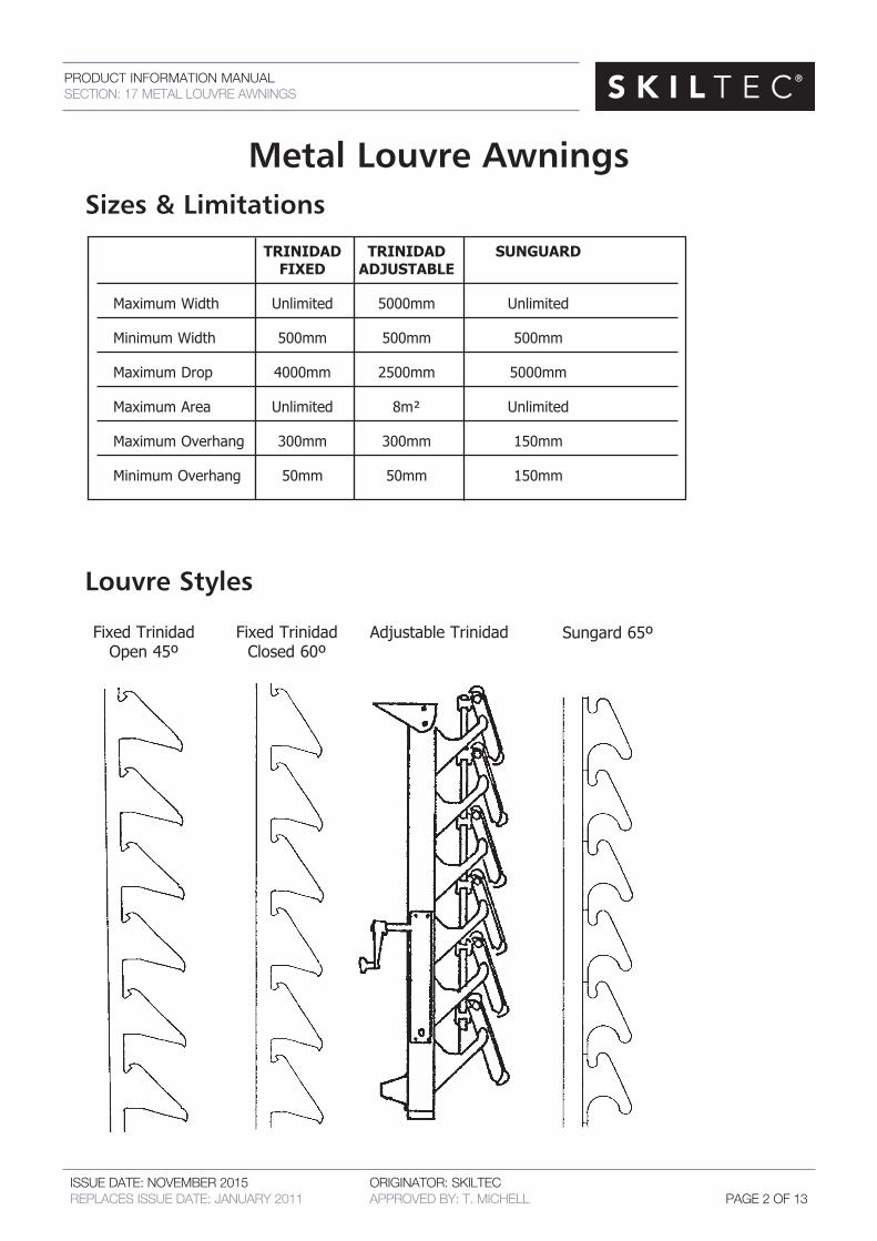
TRINIDAD TRINIDAD SUNGUARD FIXED ADJUSTABLE
Maximum Width Unlimited 5000mm Unlimited
Minimum Width 500mm 500mm 500mm
Maximum Drop 4000mm 2500mm 5000mm
Maximum Area Unlimited 8m² Unlimited
Maximum Overhang 300mm 300mm 150mm
Minimum Overhang 50mm 50mm 150mm
Louvre Styles
Sizes & Limitations
Fixed Trinidad Open 45º
Fixed Trinidad Closed 60º
Adjustable Trinidad Sungard 65º

PRODUCT INFORMATION MANUALSECTION: 17 METAL LOUVRE AWNINGS
ISSUE DATE: NOVEMBER 2015 ORIGINATOR: SKILTEC REPLACES ISSUE DATE: JANUARY 2011 APPROVED BY: T. MICHELL PAGE 3 OF 13
Measuring Louvre AwningsRegardless of the Louvre Awning Style, first determine the fit kit style that will be used to fit the louvred awning.
Width• Ifmeasuringclosetothewindow(minimumarmlength150mm)thenmeasureopening plusaminimumof150mmovereachside.
• Ifmeasuringfromthefaciaortheouteredgeoftheeavethenmeasureopeningplusa minimumof300movereachside.
Drop• Ifmeasuringfromundertheeave,measuretodesireddroporifmeasuringonablack wallabovethewindow,thenmeasurefromaminimumof2bricksabovetheopeningto the desired drop.
NOTE: The further out from a window you measure the higher and wider you will need to measure. Beware of sun coming over the top of through the sides of the Louvre Awning if measuring far out from thewindow. In some situations youmayhave to infill the top of the louvredAwningwithlouvresorcoverthetopwithabahamaawningpanel(seefitkitC).
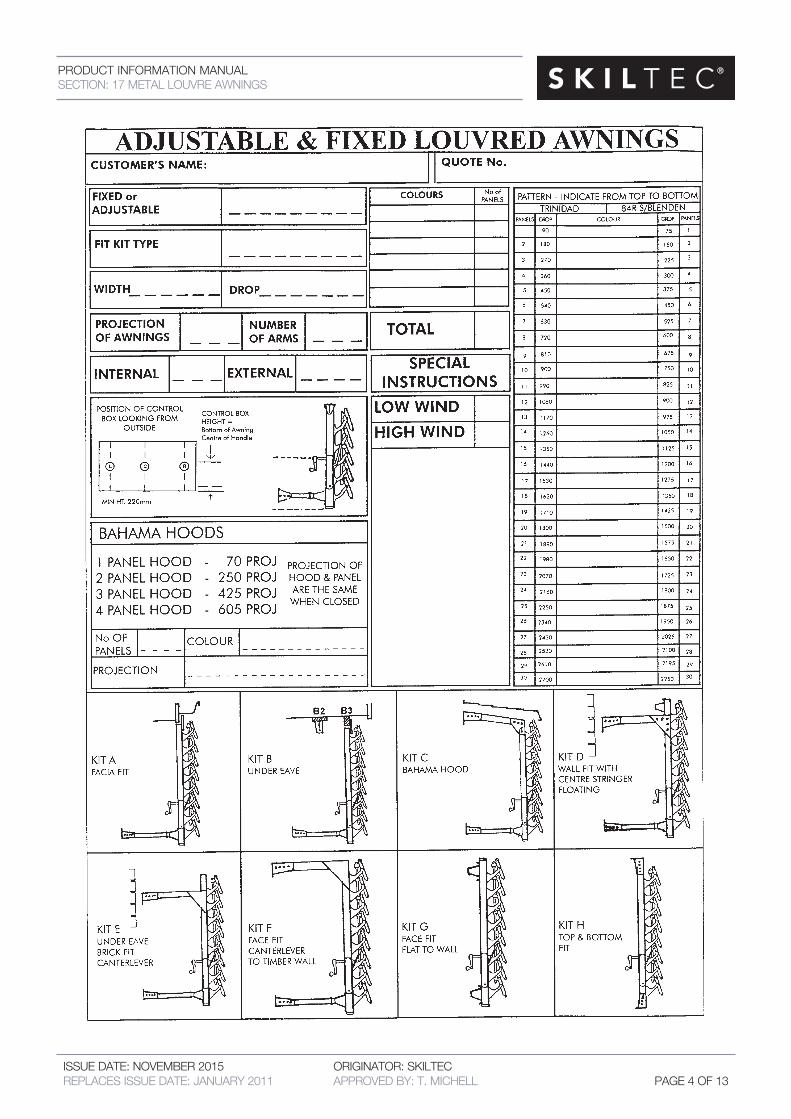
Theadjustableandfixedlouvredawningchartmustbecompletedandattachedtoeachorderfor louvre awnings.
KIT A FACIA FIT
KIT B UNDER EAVE
KIT C BAHAMA
HOOD
KIT D WALL FIT
WITH CENTRE
STRINGER FLOATING
KIT E UNDER EAVE
BRICK FIT CANTERLEVER
KIT F FACE FIT
CANETERLEVER TO TIMBER WALL
KIT G FACE FIT FLAT TO
WALL
KIT H TOP AND
BOTTOM FIT
PRODUCT INFORMATION MANUALSECTION: 17 METAL LOUVRE AWNINGS
ISSUE DATE: NOVEMBER 2015 ORIGINATOR: SKILTEC REPLACES ISSUE DATE: JANUARY 2011 APPROVED BY: T. MICHELL PAGE 4 OF 13
PRODUCT INFORMATION MANUALSECTION: 17 METAL LOUVRE AWNINGS
ISSUE DATE: NOVEMBER 2015 ORIGINATOR: SKILTEC REPLACES ISSUE DATE: JANUARY 2011 APPROVED BY: T. MICHELL PAGE 5 OF 13
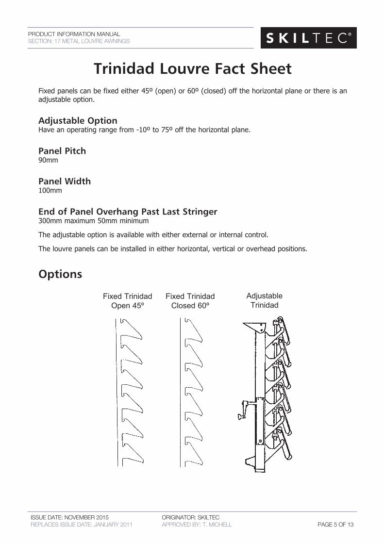
Trinidad Louvre Fact SheetFixedpanelscanbefixedeither45º(open)or60º(closed)offthehorizontalplaneorthereisanadjustable option.
Adjustable OptionHaveanoperatingrangefrom-10ºto75ºoffthehorizontalplane.
Panel Pitch90mm
Panel Width100mm
End of Panel Overhang Past Last Stringer300mm maximum 50mm minimum
Theadjustableoptionisavailablewitheitherexternalorinternalcontrol.
Thelouvrepanelscanbeinstalledineitherhorizontal,verticaloroverheadpositions.
Options
Fixed Trinidad Open 45º
Fixed Trinidad Closed 60º
Adjustable Trinidad
PRODUCT INFORMATION MANUALSECTION: 17 METAL LOUVRE AWNINGS
ISSUE DATE: NOVEMBER 2015 ORIGINATOR: SKILTEC REPLACES ISSUE DATE: JANUARY 2011 APPROVED BY: T. MICHELL PAGE 6 OF 13
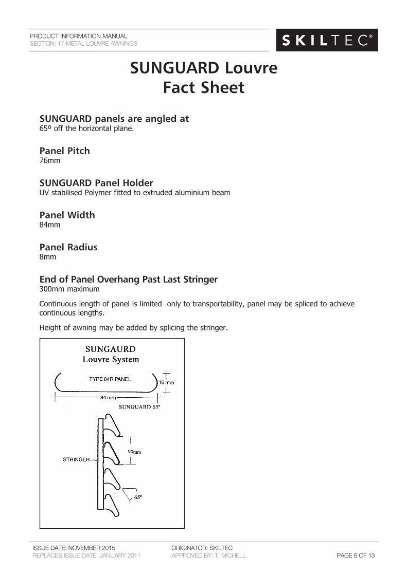
SUNGUARD Louvre Fact Sheet
SUNGUARD panels are angled at65ºoffthehorizontalplane.
Panel Pitch76mm
SUNGUARD Panel HolderUV stabilised Polymer fitted to extruded aluminium beam
Panel Width84mm
Panel Radius8mm
End of Panel Overhang Past Last Stringer300mm maximum
Continuouslengthofpanelislimitedonlytotransportability,panelmaybesplicedtoachieve continuouslengths.
Heightofawningmaybeaddedbysplicingthestringer.
PRODUCT INFORMATION MANUALSECTION: 17 METAL LOUVRE AWNINGS
ISSUE DATE: NOVEMBER 2015 ORIGINATOR: SKILTEC REPLACES ISSUE DATE: JANUARY 2011 APPROVED BY: T. MICHELL PAGE 7 OF 13
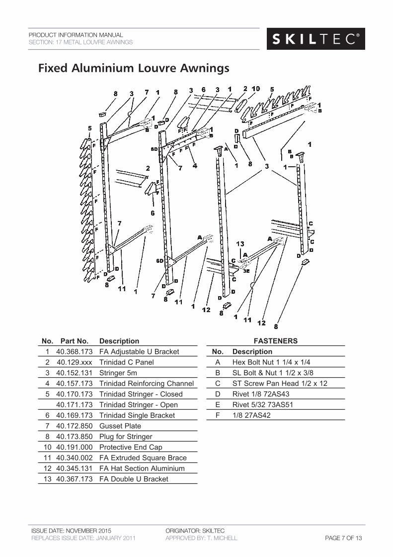
Fixed Aluminium Louvre Awnings
No. Part No. Description 1 40.368.173 FA Adjustable U Bracket 2 40.129.xxx Trinidad C Panel 3 40.152.131 Stringer 5m 4 40.157.173 Trinidad Reinforcing Channel 5 40.170.173 Trinidad Stringer - Closed 40.171.173 Trinidad Stringer - Open 6 40.169.173 Trinidad Single Bracket 7 40.172.850 Gusset Plate 8 40.173.850 Plug for Stringer 10 40.191.000 Protective End Cap 11 40.340.002 FA Extruded Square Brace 12 40.345.131 FA Hat Section Aluminium 13 40.367.173 FA Double U Bracket
FASTENERS No. Description A Hex Bolt Nut 1 1/4 x 1/4 B SL Bolt & Nut 1 1/2 x 3/8 C ST Screw Pan Head 1/2 x 12 D Rivet 1/8 72AS43 E Rivet 5/32 73AS51 F 1/8 27AS42
PRODUCT INFORMATION MANUALSECTION: 17 METAL LOUVRE AWNINGS
ISSUE DATE: NOVEMBER 2015 ORIGINATOR: SKILTEC REPLACES ISSUE DATE: JANUARY 2011 APPROVED BY: T. MICHELL PAGE 8 OF 13
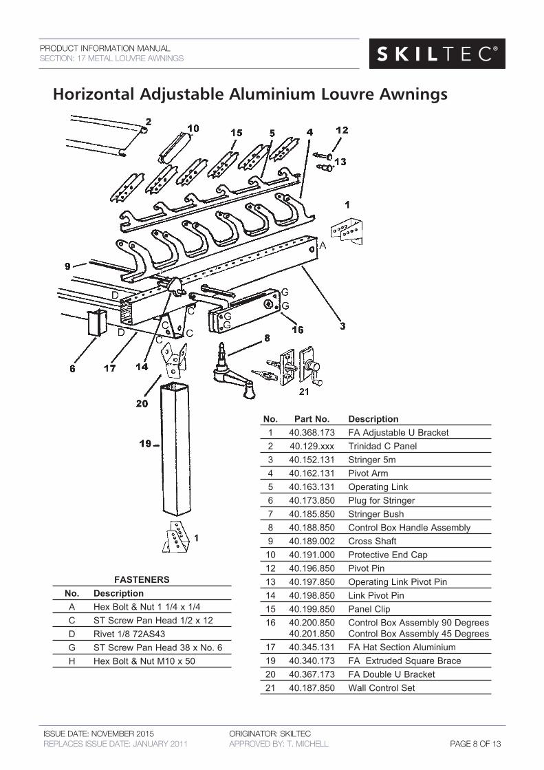
No. Part No. Description 1 40.368.173 FA Adjustable U Bracket 2 40.129.xxx Trinidad C Panel 3 40.152.131 Stringer 5m 4 40.162.131 Pivot Arm 5 40.163.131 Operating Link 6 40.173.850 Plug for Stringer 7 40.185.850 Stringer Bush 8 40.188.850 Control Box Handle Assembly 9 40.189.002 Cross Shaft 10 40.191.000 Protective End Cap 12 40.196.850 Pivot Pin 13 40.197.850 Operating Link Pivot Pin 14 40.198.850 Link Pivot Pin 15 40.199.850 Panel Clip 16 40.200.850 Control Box Assembly 90 Degrees 40.201.850 Control Box Assembly 45 Degrees 17 40.345.131 FA Hat Section Aluminium 19 40.340.173 FA Extruded Square Brace 20 40.367.173 FA Double U Bracket 21 40.187.850 Wall Control Set
FASTENERS No. Description A Hex Bolt & Nut 1 1/4 x 1/4 C ST Screw Pan Head 1/2 x 12 D Rivet 1/8 72AS43 G ST Screw Pan Head 38 x No. 6 H Hex Bolt & Nut M10 x 50
Horizontal Adjustable Aluminium Louvre Awnings
PRODUCT INFORMATION MANUALSECTION: 17 METAL LOUVRE AWNINGS
ISSUE DATE: NOVEMBER 2015 ORIGINATOR: SKILTEC REPLACES ISSUE DATE: JANUARY 2011 APPROVED BY: T. MICHELL PAGE 9 OF 13
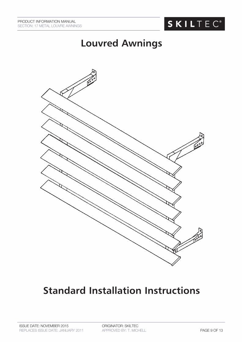
Louvred Awnings
Standard Installation Instructions
PRODUCT INFORMATION MANUALSECTION: 17 METAL LOUVRE AWNINGS
ISSUE DATE: NOVEMBER 2015 ORIGINATOR: SKILTEC REPLACES ISSUE DATE: JANUARY 2011 APPROVED BY: T. MICHELL PAGE 10 OF 13
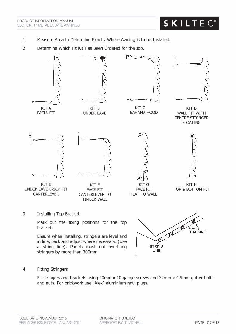
1. MeasureAreatoDetermineExactlyWhereAwningistobeInstalled.
2. DetermineWhichFitKitHasBeenOrderedfortheJob.
3. InstallingTopBracket
Mark out the fixing positions for the top bracket.
Ensure when installing, stringers are level and inline,packandadjustwherenecessary.(Use a string line). Panels must not overhang stringers by more than 300mm.
4. Fitting Stringers
Fitstringersandbracketsusing40mmx10gaugescrewsand32mmx4.5mmgutterbolts andnuts.Forbrickworkuse“Alex”aluminiumrawlplugs.
KITE UNDEREAVEBRICKFIT
CANTERLEVER
KITF FACEFIT
CANTERLEVER TO TIMBERWALL
KITG FACEFIT
FLAT TO WALL
KITH TOP&BOTTOMFIT
KITA FACIAFIT
KITB UNDER EAVE
KITC BAHAMA HOOD
KITD WALLFITWITH CENTRESTRINGER
FLOATING
PRODUCT INFORMATION MANUALSECTION: 17 METAL LOUVRE AWNINGS
ISSUE DATE: NOVEMBER 2015 ORIGINATOR: SKILTEC REPLACES ISSUE DATE: JANUARY 2011 APPROVED BY: T. MICHELL PAGE 11 OF 13
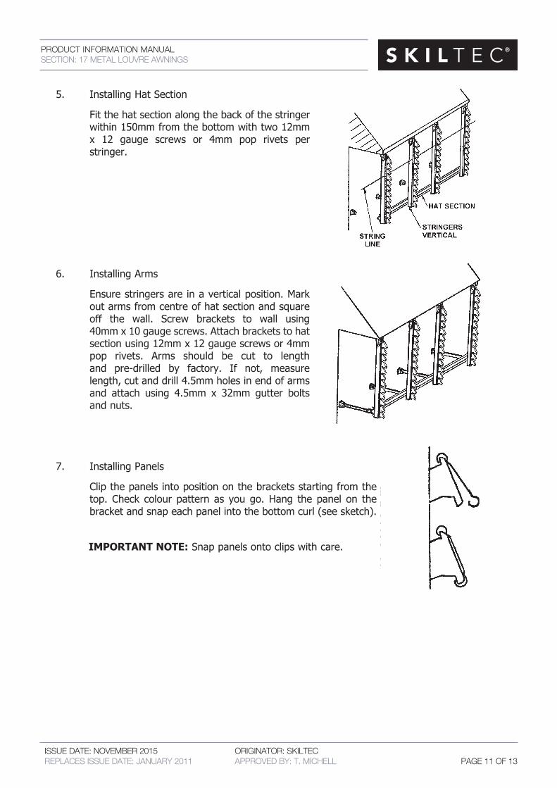
5. InstallingHatSection
Fitthehatsectionalongthebackofthestringer within 150mm from the bottom with two 12mm x 12 gauge screws or 4mm pop rivets per stringer.
6. InstallingArms
Ensurestringersareinaverticalposition.Mark outarmsfromcentreofhatsectionandsquare off the wall. Screw brackets to wall using 40mmx10gaugescrews.Attachbracketstohat sectionusing12mmx12gaugescrewsor4mm pop rivets. Arms should be cut to length and pre-drilled by factory. If not, measure length,cutanddrill4.5mmholesinendofarms and attach using 4.5mm x 32mm gutter bolts and nuts.
7. InstallingPanels
Clipthepanelsintopositiononthebracketsstartingfromthe top.Check colour pattern as yougo.Hang thepanel on the bracketandsnapeachpanelintothebottomcurl(seesketch).
IMPORTANT NOTE:Snappanelsontoclipswithcare.
PRODUCT INFORMATION MANUALSECTION: 17 METAL LOUVRE AWNINGS
ISSUE DATE: NOVEMBER 2015 ORIGINATOR: SKILTEC REPLACES ISSUE DATE: JANUARY 2011 APPROVED BY: T. MICHELL PAGE 12 OF 13
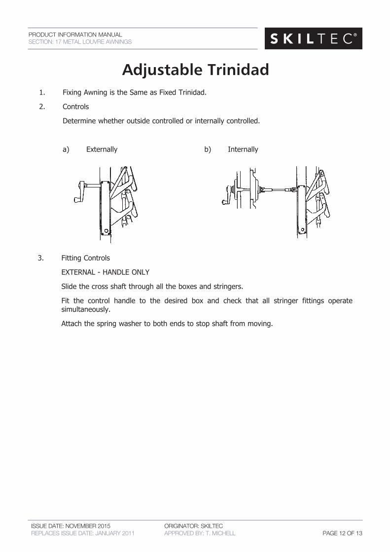
Adjustable Trinidad1. Fixing Awning is the Same as Fixed Trinidad.
2. Controls
Determinewhetheroutsidecontrolledorinternallycontrolled.
a) Externally b) Internally
3. Fitting Controls
EXTERNAL - HANDLE ONLY
Slidethecrossshaftthroughalltheboxesandstringers.
Fit the control handle to the desired box and check that all stringer fittings operate simultaneously.
Attachthespringwashertobothendstostopshaftfrommoving.
PRODUCT INFORMATION MANUALSECTION: 17 METAL LOUVRE AWNINGS
ISSUE DATE: NOVEMBER 2015 ORIGINATOR: SKILTEC REPLACES ISSUE DATE: JANUARY 2011 APPROVED BY: T. MICHELL PAGE 13 OF 13
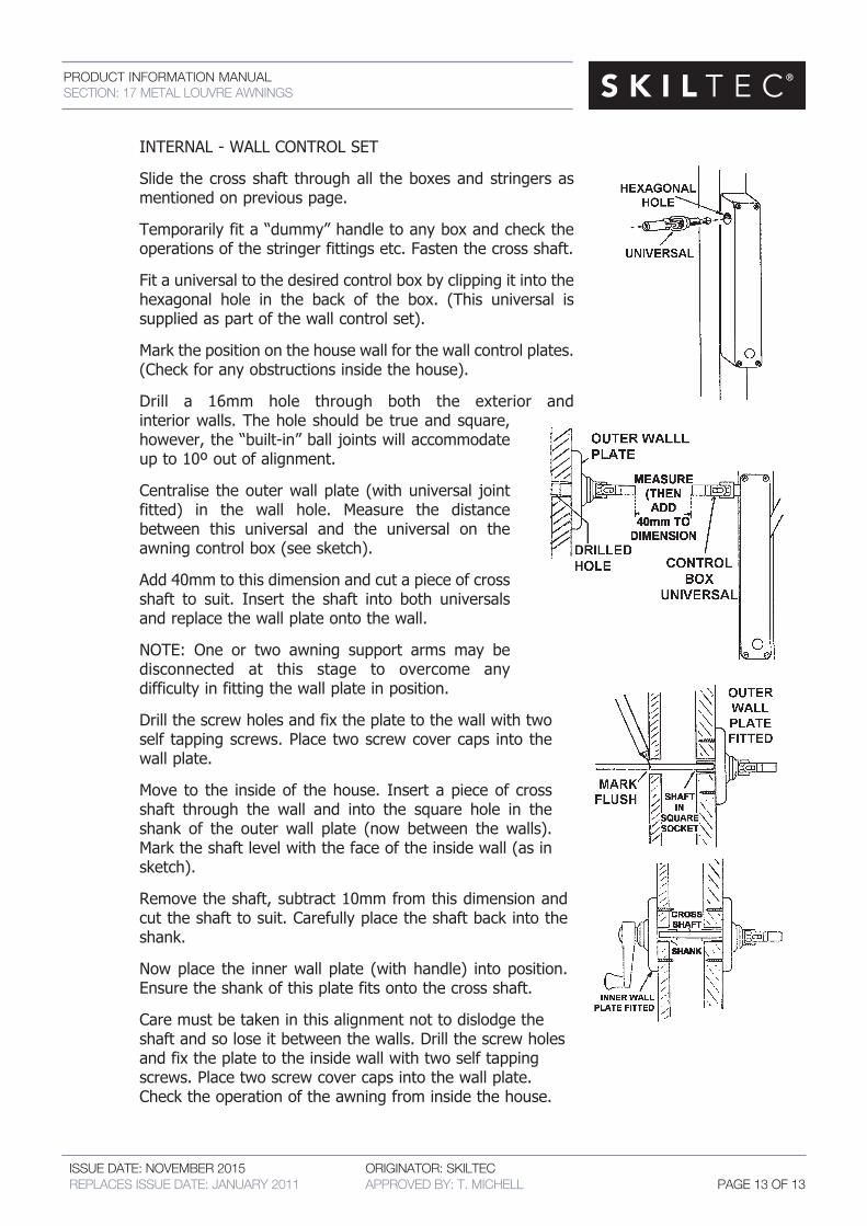
INTERNAL-WALLCONTROLSET
Slide thecrossshaft throughall theboxesandstringersas mentioned on previous page.
Temporarilyfita“dummy”handletoanyboxandcheckthe operationsofthestringerfittingsetc.Fastenthecrossshaft.
Fitauniversaltothedesiredcontrolboxbyclippingitintothe hexagonal hole in the back of the box. (This universal is suppliedaspartofthewallcontrolset).
Markthepositiononthehousewallforthewallcontrolplates. (Checkforanyobstructionsinsidethehouse).
Drill a 16mm hole through both the exterior and interiorwalls.Theholeshouldbetrueandsquare, however,the“built-in”balljointswillaccommodate up to 10º out of alignment.
Centralise theouterwallplate (withuniversal joint fitted) in the wall hole. Measure the distance between this universal and the universal on the awningcontrolbox(seesketch).
Add40mmtothisdimensionandcutapieceofcross shaft to suit. Insert the shaft into both universals andreplacethewallplateontothewall.
NOTE: One or two awning support arms may be disconnected at this stage to overcome any difficultyinfittingthewallplateinposition.
Drillthescrewholesandfixtheplatetothewallwithtwo self tappingscrews.Placetwoscrewcovercaps intothe wall plate.
Move to the insideof thehouse. Insertapieceof cross shaft through the wall and into the square hole in the shank of the outer wall plate (now between the walls). Marktheshaftlevelwiththefaceoftheinsidewall(asin sketch).
Removetheshaft,subtract10mmfromthisdimensionand cuttheshafttosuit.Carefullyplacetheshaftbackintothe shank.
Nowplace the innerwallplate (withhandle) intoposition. Ensuretheshankofthisplatefitsontothecrossshaft.
Care must be taken in this alignment not to dislodge the shaftandsoloseitbetweenthewalls.Drillthescrewholes and fix the plate to the inside wall with two self tapping screws.Placetwoscrewcovercapsintothewallplate. Checktheoperationoftheawningfrominsidethehouse.