metal forming handbook - home - springer978-3-642-58857-0/1.pdf · this handbook is the product of...
TRANSCRIPT

SCHULER~
Metal Forming Handbook

Springer-Verlag Berlin Heidelberg GmbH
, Springer
SCHUL R~
METAL FORMING HANDBOOK
SCHULER GmbH Bahnhofstr. 41 73033 Goppingen Germany
Consulting editor: Professor Taylan Altan Director, Engineering Research Center for Net Shape Manufacturing The Ohio State University, USA
Library of Congress Cataloging-in-Publication Data
Handbuch der Umformtechnik. English Metal forming handbook / Schuler GmbH. Includes bibliographical references and index. ISBN 978-3-642-63763-6 ISBN 978-3-642-58857-0 (eBook) DOI 10.1007/978-3-642-58857-0 1. Metal-work. 1. Schuler GmbH. II. Title.
TS20S.H33413 1998 671--dc21 98-22434
ISBN 978-3-642-63763-6
This work is subject to copyright. AII rights are reserved, whether the whole part of the material is concerned, specifically the rights of translation, reprinting, reuse of illustrations, recitation, broadcasting, reproduction on microfilm or in any other way, and storage in data banks. Duplication of this publicat ion or parts thereof is permitted only under the provisions of the German Copyright Law of September 9,1965, in its current version, and permis sion for use must always be obtained from Springer-Verlag. Violations are liable for prosecut ion under the German Copyright Law.
© Springer-Verlag Berlin Heidelberg 1998 Originally published by Springer-Verlag Berlin Heidelberg New York in 1998 Softcover reprint of the hardcover 1 st edition 1998 The use of general descriptive names, registered names, trademarks, etc. in this publicat ion does not imply, even in the absence of a specific statement, that such names are exempt from the relevant protective laws and regulations and therefore free for general use.
Cover design by MEDIO, Berlin Layout design and data conversion by K.-D. Grotz, MEDIO, Berlin
SPIN: 10712900 3020/ 62/ 5 4 3 2 1 - Printed on acid-free paper.
Preface
Following the long tradition of the Schuler Company, the Metal Forming Handbook presents the scientific fundamentals of metal forming technology in a way which is both compact and easily understood. Thus, this book makes the theory and practice of this field accessible to teaching and practical implementation.
The first Schuler "Metal Forming Handbook" was published in 1930. The last edition of 1966, already revised four times, was translated into a number of languages, and met with resounding approval around the globe.
Over the last 30 years, the field of forming technology has been radically changed by a number of innovations. New forming techniques and extended product design possibilities have been developed and introduced. This Metal Forming Handbook has been fundamentally revised to take account of these technological changes. It is both a textbook and a reference work whose initial chapters are concerned to provide a survey of the fundamental processes of forming technology and press design. The book then goes on to provide an in-depth study of the major fields of sheet metal forming, cutting, hydroforming and solid forming. A large number of relevant calculations offers state of the art solutions in the field of metal forming technology. In presenting technical explanations, particular emphasis was placed on easily understandable graphic visualization. All illustrations and diagrams were compiled using a standardized system of functionally oriented color codes with a view to aiding the reader's understanding.
It is sincerely hoped that this Handbook helps not only disseminate specialized knowledge but also provides an impetus for dialogue between the fields of production engineering, production line construction, teaching and research.
_ VI
This Handbook is the product of dedicated commitment and the wide range of specialized knowledge contributed by many employees of the SCHULER Group in close cooperation with Prof. Dr.-Ing. H. Hoffmann and Dipl.-Ing. M. Kasparbauer of the utg, Institute for Metal Forming and Casting at the Technical University of Munich. In close cooperation with the SCHULER team, they have created a solid foundation for the practical and scientific competence presented in this Handbook. We wish to offer our sincere thanks and appreciation to all those involved.
Goeppingen, March 1998
Schuler GmbH Board of Management
Contnbu or
ADAM, K., Dipl.-lng. (FH), SMG Suddeutsche Maschinenbau GmbH &: Co BAREIS, A., Dipl.-Ing. (FH), Schuler Pressen GmbH &: Co BIRZER, F., Prof. Dipl.-lng., Feintool AG BLASIG, N., Dipl.-Ing. (FH), Schleicher Automation GmbH &: Co BRANDSTETTER, R., Dipl.-lng. (FH), Schuler Pressen GmbH &: Co BREUER, W., Dipl.-lng., Schuler Pressen GmbH &: Co FRONTZEK, H., Dr.-Ing., Schuler GmbH HOFFMANN, H ., Prof. Dr.-lng., Lehrstuhl fur Umformtechnik und GieBe-
reiwesen, Technische Universitat Munchen JAROSCH, B., Dipl.-Ing. (FH), Schuler Pressen GmbH &: Co KASMACHER, H., SMG Engineering fur lndustrieanlagen GmbH KASPARBAUER, M., Dipl.-lng. , Lehrstuhl fur Umformtechnik und GieBerei-
wesen, Technische Universitat Munchen KELLENBENZ, R., Dipl.-Ing. (FH), Schuler Pressen GmbH &: Co KIEFER, A., Dipl.-Ing. (BA), GMG Automation GmbH &: Co KLEIN, P., Grabener Pressensysteme GmbH &: Co. KG KLEMM, P., Dr.-Ing., Schuler Pressen GmbH &: Co KNAUR, v., Dipl.-Ing. (FH), Schuler Werkzeuge GmbH &: Co KOHLER, H. , Dipl.-lng., Schuler GuB GmbH &: Co KORNER, E., Dr.-Ing., Schuler Pressen GmbH &: Co KUTSCHER, H.-W., Dipl.-Ing. (FH), Grabener Pressensysteme GmbH &: Co. KG LEITLOFF, F.-U., Dr.-lng., Schafer Hydroforming GmbH &: Co MERKI.E, D. , Schuler Pressen GmbH &: Co OSLN, W., Dr.- Ing., SMG Suddeutsche Maschinenbau GmbH &: Co PtElFI.E, P. , Dipl.-Ing. (FH), Schuler Pressen GmbH &: Co REITMEIER, c., Dipl.-Ing., Schafer Hydroforming GmbH &: Co REMPPIS, M., Ing. grad., Schuler Pressen GmbH &: Co ROSENAUER, K., Dipl.-Ing. (FH), Schuler Werkzeuge GmbH &: Co

_ VIII Met'/ F"mi'g H"dbook I SCHAFER, A.W., Schafer Hydroforming GmbH & Co SCHMID, W., Dipl.-Ing. (FH), Schuler Werkzeuge GmbH & Co SCHMITI, K. P., Schuler Pressen GmbH & Co SCHNEIDER, F., Dipl.-Ing. (FH), Schuler Pressen GmbH & Co SIMON, H., Dr.-Ing., Schuler Werkzeuge GmbH & Co STEINMETZ, M., Dipl.-Wirt.-Ing., SMG Engineering fur Industrieanlagen
GmbH STROMMER, K., Dipl.-Ing. (FH), Schuler Pressen GmbH & Co VOGEL, N., Dipl.-Ing., Schleicher Automation GmbH & Co WEGENER, K., Dr.-Ing., Schuler Pressen GmbH & Co

Contents
Index of formula symbols ............... . . ........ ... ... xv
• 1 Introduction .. ... .. .. . ............. .. .. . ..... . ...... 1
• 2 Basic principles of metal forming ...................... S
2.1 Methods of forming and cutting technology. . . . . . . . . S 2.1.1 Summary . .............. . ... . ........ . .... S 2.1.2 Forming .................................. 6 2.1.3 Dividing.................................. 19 2.1.4 Combinations of processes in manufacturing. . . .. 22
2.2 Basic terms . . . . . . . . . . . . . . . . . . . . . . . . . . . . . . . . . . . .. 25 2.2.1 Flow condition and flow curve. . . . . . . . . . . . . . . .. 2S 2.2.2 Deformation and material flow . . . . . . . . . . . . . . .. 26 2.2.3 Force and work. . . . . . . . . . . . . . . . . . . . . . . . . . . .. 28 2.2.4 Formability.. . . . .......... .. .. . ............ 30 2.2.5 Units of measurement . . . . . . . . . . . . . . . . . . . . . .. 31
Bibliography . . . . . . . . . . . . . . . . . . . . . . . . . . . . . . . . . . . . . . . .. 32
3 Fundamentals of press design. . . . . . . . . . . . . . . . . . . . . . . . .. 33
3.1 Press types and press construction. . . . . . . . . . . . . . . . .. 33 3.1.1 Press frame . . . . . . . . . . . . . . . . . . . . . . . . . . . . . . .. 34 3.1.2 Slide drive . . . . . . . . . . . . . . . . . . . . . . . . . . . . . . . .. 37 3.1.3 Drive systems for deep drawing presses. . . . . . . . .. 41 3.1.4 Draw cushions . ..... . . . . . . . . . . . . . . . . . . . . . .. 44
_ x
3.2 Mechanical presses .. . ...... .. .......... .. ....... 49 3.2.1 Determination of characteristic data .. ..... .. .. 49 3.2.2 Types of drive system ...... .. . .. ... . ...... .. 54 3.2.3 Drive motor and flywheel. . . . . . . . . . . . . . . . . . .. 60 3.2.4 Clutch and brake ....... .. ... . .... . ........ 61 3.2.5 Longitudinal and transverse shaft drive. . . . . . . .. 63 3.2.6 Gear drives .. . .... . ................... .. .. 65 3.2.7 Press crown assembly . .. . .. . ........ . .... . . . 66 3.2.8 Slide and blank holder ..... .... .. .. .. . . .... . 66 3.2.9 Pneumatic system. . . . . . . . . . . . . . . . . . . . . . . . . . 70 3.2.10 Hydraulic system. . . . . . . . . . . . . . . . . . . . . . . . . . . 71 3.2.11 Lubrication ......... .. ....... .. ... . . . ..... 72
3.3 Hydraulic presses ...... . .... ... ...... . .......... 73 3.3.1 Drive system . .. .......... ..... .. ... ... . ... 73 3.3.2 Hydraulic oil . . . . . . . . . . . . . . . . . . . . . . . . . . . . . . 77 3.3.3 Parallelism of the slide ... .. . . .... . .......... 80 3.3.4 Stroke limitation and damping .... . . .... .. ... 82 3.3.5 Slide locking .. . .... . ......... . .. .. ........ 83
3.4 Changing dies .... . ............ . . . .... . ... . ..... 86 3.4.1 Die handling . . . . . . . . . . . . . . . . . . . . . . . . . . . . .. 86 3.4.2 Die clamping devices ................... . . . . 91
3.5 Press control systems ...... . . . .. . .... . .... . .... . . 94 3.5.1 Functions of the control system . . . . . . . . . . . . . .. 94 3.5.2 Electrical components of presses . .. . .... . ..... 94 3.5.3 Operating and visualization system . . . . . . . . . . . . 95 3.5.4 Structure of electrical control systems ........ .. 97 3.5.5 Functional structure of the control system . ..... 99 3.5.6 Major electronic control components ..... .. ... 99 3.5.7 Architecture and hardware configuration .... . .. 101 3.5.8 Architecture of the PLC software ... . ......... . 101 3.5 .9 Future outlook ...... . ..... .. . ............. 102
3.6 Press safety and certification . . . . . . . . . . . . . . . . . . . . .. 106 3.6.1 Accident prevention . .. . . . . . . . . . . . . . . . . . . . .. 106 3.6.2 Legislation.......... . .. .. . . . ..... . .... . ... 107 3.6.3 European safety requirements ... . ... .. ....... 107 3.6.4 CE marking . . . . . . . . . . . . . . . . . . . . . . . . . . . . . . . 111

3.6.5 Measures to be undertaken by the user ..... . ... 115 3.6.6 Safety requirements in the USA . . . .. . ......... 117
3.7 Casting components for presses ............. . ..... 120
Bibliography. . . . . . . . . . . . . . . . . . . . . . . . . . . . . . . . . . . . . . . .. 122
• 4 Sheet metal forming and blanking .......... . ...... . .. 123 4.1 Principles of die manufacture ....... . .. . .. ... . . . .. 123
4.1.1 Classification of dies . . . . . . . . . . . . . . . . . . . . . . .. 123 4.1.2 Die development .......................... 128 4.1.3 Die materials ..................... . . . ...... 142 4.1.4 Casting of dies. . . . . . . . . . . . . . . . . . . . . . . . . . . .. 142 4.1.5 Try-out equipment . . . . .. ..... . .. . ... . . ... .. 148 4.1.6 Transfer simulators .............. . .. . . ... ... 154
4.2 Deep drawing and stretch drawing. . . . . . . . . . . . . . . .. 156 4.2.1 Forming process ........................... 156 4.2.2 Materials for sheet metal forming . . ........... 174 4.2.3 Friction, wear and lubrication during
sheet metal forming . ....... . ........... . ... 179 4.2.4 Hydro-mechanical deep drawing . . . . . . . . . . . . .. 185 4.2.5 Active hydro-mechanical drawing .. . . . . . . . . . .. 188
4.3 Coil lines .. .. .... . ....... .. ..... . .. . .... ... . . .. 194
4.4 Sheet metal forming lines .. ............... ..... .. 198 4.4 .1 Universal presses ................. . ......... 198 4.4.2 Production lines for the manufacture of
flat radiator plates ............... . ......... 208 4.4.3 Lines for side member manufacture. . . . . . . . . . .. 210 4.4.4 Destackers and blank turnover stations ... ... .. 217 4.4.5 Press lines .. .. .............. . ......... .. .. 222 4.4.6 Transfer presses for small and
medium sized parts. . . . . . . . . . . . . . . . . . . . . . . .. 229 4.4.7 Large-panel tri-axis transfer presses .. .. .. ..... . 234 4.4.8 Crossbar transfer presses . . . . . . . . . . . . . . . . . . . .. 243 4.4.9 Presses for plastics. . . . . . . . . . . . . . . . . . . . . . . . . . 250 4.4.10 Stacking units for finished parts . .. ..... . ...... 252 4.4.11 Control systems for large-panel transfer presses . . 254
XI _
_ XII
4.5 Blanking processes .. .. .......................... 268
4.6 Shearing lines . . ... .. .. . ..... . . ... . ... . . . .... .. . 284 4.6.1 Slitting lines ..... . . . ......... . ............ 284 4.6.2 Blanking lines . . . . . . . . . . . . . . . . . . . . . . . . . . . .. 286 4.6.3 High-speed blanking lines . .... . ..... . ....... 291 4.6.4 Lines for the production of
electric motor laminations . . . . . . . . . . . . . . . . . .. 296 4.6.5 Production and processing of tailored blanks .... 310 4.6.6 Perforating presses ............. . ........... 314 4.6.7 Control systems for blanking presses . . . . . . . . . .. 320
4.7 Fine blanking ..... . ......... . . . ........... .. ... , 330 4.7.1 Fine blanking process. . . . . . . . . . . . . . . . . . . . . .. 330 4.7.2 Fine blanking materials, forces, quality
characteristics and part variety . . . . . . . . . . . . . . .. 338 4.7.3 Fine blanking tools . . . . . . . . . . . . . . . . . . . . . . . .. 351 4.7.4 Fine blanking presses and lines ... . .... .. ..... 359
4.8 Bending ....... ... .... . .... . ....... .. ... . . . ... . 366 4.8.1 Bending process ........ . . . .......... ... ... 366 4.8.2 Roll forming and variety of sections . . . . . . . . . . . . 373 4.8.3 Roller straightening . ............ . .......... 383
4.9 Organization of stamping plants .................. 389 4.9.1 Design ...... . ... . ........................ 389 4.9.2 Layout...... . ... . ........ . ......... . ..... 391 4.9.3 Quality assurance through quality control . . .... 398
Bibliography . . . . . . . . . . . . . . . . . . . . . . . . . . . . . . . . . . . . . . . . . 403
5 Hydroforming . . . . . . . . . . . . . . . . . . . . . . . . . . . . . . . . . . . . .. 405
5.1 General........... . ... . . . ................... . .. 405
5.2 Process technology and example applications .... .. . 405 5.2.1 Process technology. . . . . . . . . . . . . . . . . . . . . . . . . 405 5.2.2 Types of hydroformed components . . . . . . . . . . . . 408 5.2.3 Fields of application ............ . ........ . . . 410
5.3 Component development ............ .. .......... . 413 5.3.1 User-oriented project management ..... ... . .. . 413 5.3.2 Feasibility studies ... .... . . ................ . 414 5.3.3 Component design ...... ... ... . ........... . 416
5.4 Die engineering ......... ... .... . ............... . 420 5.4.1 Die layout ... . ......... . ... ... . .. ......... . 420 5.4.2 Lubricants ....................... . ....... . 422
5.5 Materials and preforms for producing hydroformed components .... . . ... . ... . 423 5.5.1 Materials and heat treatment ................ . 423 5.5.2 Preforms and preparation . ..... .. . . ......... . 424
5.6 Presses for hydroforming ...... . ... ... . .......... . 426
5.7 General considerations .. ......... . . .... ..... .... . 429 5.7.1 Production technology issues .... ... ...... . .. . 429 5.7.2 Technical and economic considerations ....... . 431
Bibliography ...... ... ............................... . 432
• 6 Solid forming (Forging) .............................. 433
6.1 General.............. .. ..... ... ................ 433
6.2 Benefits of solid forming ...... ... . ......... . . .. .. 441 6.2.1 Economic aspects ...... . ... . .. .. ...... ... .. 441 6.2.2 Workpiece properties. . . . . . . . . . . . . . . . . . . . . . .. 443
6.3 Materials, billet production and surface treatment .. . 450 6.3.1 Materials................... . .. . .. ......... 450 6.3.2 Billet or slug preparation ........ .. ......... " 454 6.3.3 Surface treatment. . . . . . . . . . . . . . . . . . . . . . . . . .. 459
6.4 Formed part and process plan . . . . . . . . . . . . . . . . . . . .. 464 6.4.1 The formed part . . . . . . . . . . . . . . . . . . . . . . . . . . .. 464 6.4.2 Process plan . . . . ... ..... . . .... . . .... ..... " 467
6.5 Force and work requirement . . . . . . . . . . . . . . . . . . . . .. 469 6.5.1 Forward rod extrusion. . . . . . . . . . . . . . . . . . . . . . . 469 6.5.2 Forward tube extrusion. . . . . . . . . . . . . . . . . . . . .. 474
XIII -

_ XIV
6.5.3 Backward cup extrusion and centering ......... 474 6.5.4 Reducing (open die forward extrusion) .......... 475 6.5.5 Ironing................. . ....... .... ...... 476 6.5.6 Upsetting....... .. ..................... ... 476 6.5.7 Lateral extrusion. . . . . . . . . . . . . . . . . . . . . . . . . .. 477
6.6 Part transfer . . . . . . . . . . . . . . . . . . . . . . . . . . . . . . . . . . .. 478 6.6.1 Loading station. . . . . . . . . . . . . . . . . . . . . . . . . . . . 479 6.6.2 Transfer study .......... . . . ... . ... . ..... ... 481
6.7 Die design ... . . . .................... . .......... 485 6.7.1 Die holders .. ....... . .... ... .. .. . . . ... . ... 488 6.7.2 Die and punch design .... . ................. 491 6.7.3 Die and punch materials . .... ........ . . . .... 496 6.7.4 Die closing systems
(multiple-action dies) ..... . . . ... ... ... . ..... 502
6.8 Presses used for solid forming .. ........... .. ..... 505 6.8.1 Choice of press ......... . . . ..... . ..... . .... 505 6.8.2 Mechanical presses ............. .. .......... 507 6.8.3 Hydraulic presses . . .... . . . ..... . . . ......... 514 6.8.4 Supplementary equipment .................. 517 6.8.5 Special features of hot and warm forming lines .. 520 6.8.6 Sizing and coining presses ................... 522 6.8.7 Minting and coin blanking lines . ........ . .... 526
Bibliography . . . . . . . . . . . . . . . . . . . . . . . . . . . . . . . . . . . . . . . .. 541
Index .. ..... .. ...... . .... . ... .. ........ . ... . ......... 543

ndex of formula sym
rib angle, bending angle, clearance angl , di op ning angle, corner angl for blanking
r quir d bending angle
de ired bending angle
draw ratio,
o s
corner angle when bending
13101 total draw ratio
13max maximum draw ratio
elongation, tarting mea urement
relative cro s e tion change
TJ efficien y
TJA degr e of utilization of the heet metal, utilization force
TJF forming efficiency factor
CTmd
CTmln
coefficient of friction
volumetric flow
tre S
mean tre
large t tre
mean comparative tre
malle t tr
normal contact tre
radial str
o
o
o
o
o
o
o
%
I I Imm 2
Imm2
Imm 2
Imm2
I mm2
Imm2
I mm2
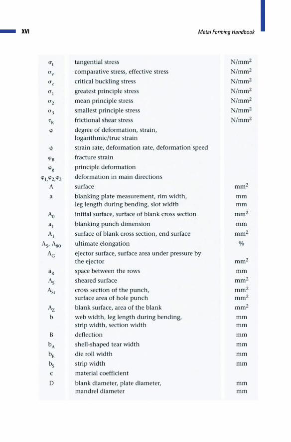
_ XVI
tangential stre s
comparative tre ,effective tress
critical buckling tre
greatest principle stres
mean principle tre
smallest principle tre
frictional shear tres
IP degree of deformation, strain, logarithmic/true strain
cp train rate, deformation rate, deformation peed
1P8 fracture strain
IPg principle deformation
a
Az b
deformation in main direction
urface
blanking plate mea urement, rim width, leg length during bending, slot width
initial sUIface, surface of blank cross cnon
blanking punch dimen ion
urface of blank cro ection, end urface
ultimate elongation
ejector urface, surface area under pressure by the ejector
pace b tween the rows
heared urface
cross section of the punch, surface area of hole punch
blank surface, area of the blank
w b width, leg length during bending, strip width, section width
deflection
hell- haped tear width
die roll width
trip width
c material coefficient
blank diam ter, plate diameter, mandr I diameter
/mm2
/mm2
/mm2
/mm2
/ mm2
N/mm2
/mm2
mm mm
mm2
mm
mm2
%
mm2
mm
mm2
mm2
mm2
mm2
mm mm
mm
mm
mm
mm
mm mm
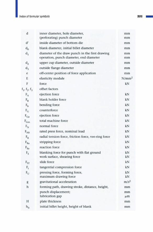
XVII _
d inner diameter, hole diameter, mm (perforating) punch diameter mm
d' inside diameter of bottom die mm
do blank diameter, initial billet diameter mm
d l diameter of the draw punch in the fir t drawing mm operation, punch diameter, end diameter mm
d2 upper cup diameter, out ide diameter mm
d3 out ide flange diameter mm
e off-center position of force application mm
E elasticity module /mm2
F force kN
fl' f2' f3 off et factor
FA ejection force k
FB blank holder force kN
Fb bending force k
Fe counterforce k
F a ej ction force k
FCe total machine force k
F normal force k
F rat d pre force, nominal load k
FR radial ten ion for e, friction force, vee-ring force k
FRa stripping force kN
FRe reaction force kN
Fs blanking force for punch with flat ground k work urface, shearing force k
F r lide force k
F\ tangential compre sion force kN
Fu pressing force, forming force, k maximum drawing force kN
g gravitational acceleration m/s2
h forming path, drawing stroke, distance, height, mm
punch displacement; mm lubrication gap jJ.m
H plate thickne mm
ho initial bill t height, height of blank mm
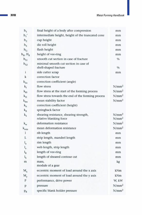
_ XVIII
h 2
M,w' Fonni', HaMbook I final height of a body after com pre ion
intermediate height, height of the truncated cone
cup height
die roll height
flash height
height of vee-ring
mooth cut section in case of fracture
minimal smooth cut section in ca e of shell-shap d fracture
ide cutter crap
mm
mm
mm
mm
mm
mm
%
%
mm
k correction factor
~" kwm
I
L
la
Ie
IR I
m
correction coefficient (angle)
flow stress
flow tre at the start of the forming proce s
flow stress toward the end of the forming proce
mean stability factor
correction coefficient (height)
springback factor
hearing resi tance, hearing trength, relative blanking force
deformation resistance
mean deformation resistance
rib length
strip length, mandrel length
rim length
web length, strip length
length of vee-ring
length of heared contour cut
rna s, module of a gear
eccentric moment of load around the x axis
eccentric moment of load around the yaxi
performance, drive power
pressure
sp cific blank holder pressure
/mm2
/ mm2
/mm2
/ mm2
/mm2 /mm2
/mm2
/mm2
mm
mm
mm
mm
mm
mm
kg
k m k m
W, kW
/mm2
/mm2

p
Pi
Pj
Pm p t
R
u
u
v
v
average compre sive tre on the counterpunch
internal pre sure
com pre ive stre at the wall of the bottom die
mean (hydraustatic) pressure
average compressive stress on the punch, average forming pressure
specific counterforce, counterpre sure
radiu
corner radius
external radius of an inside contour
external radius of an outside contour
lower yield trength
compression limit
inside bending radius, internal radius of an inside contour
internal radius of an outside contour
inside radius at the die
inside radius at the workpiece
ten ile trength of the material
urface roughness
roller radius
surface roughness
sheet metal thickness, wall thickness, blank thickness
position of the center of force (xs· und y : coordinates of the force), center of gravity
pitch
roller pitch
blanking clearance
speed/stroking speed, cut contour Circumferences, punch perimeter
counterbalance value during bending, compensation factor
feed step, volume
/ mm2
/mm2
/mm2
/mm2
/mm2 /mm2
/mm2
mm
mm
mm
mm
/mm2
/ mm2
mm mm
mm
mm
mm
/mm2
fJ.m mm
fJ.m mm mm
mm
mm
mm
mm
l / min mm
mm mm
mm mm3
XIX _
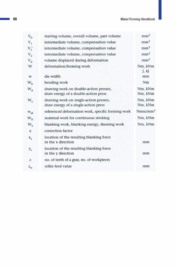
_ xx
Vo tarting volume, overall volume, part volume mm3
VI intermediate volume, compen ation value mm3
V' 1 in term diate volume, compen ation value mm3
V2 interm diate volume, comp nsat'ion value mm3
Vd volume di placed during d formation mm3
W d formation/forming work m, k m J, kJ
w die width mm
Wb bending work m
Wd drawing work on double-action presses, m,kNm draw energy of a double-action press m, k m
We drawing work on ingle-action-presses, m, k m draw energy of a single-action pre m, k m
wid referenced deformation work, pecific forming work mm/mm3
W nominal work for continuou troking Nm, k m
Ws blanking work, blanking energy, hearing work Nm, k m
x correction factor
x location of the re ulting blanking force in the x direction mm
y location of the resulting blanking force in the y direction mm
z no. of teeth of a gear, no. of workpiece
z..v roller feed value mm