meridian double wall galvanized grain bin operators manual
TRANSCRIPT

Galvanized Double Corrugated
Grain Bins
www.MeridianMFG.com

2 Grain Bin Assembly manual 21-27 January 2016 V1.3
TABLE OF CONTENTS Table of Contents .......................................................................................................................................................... 2
Safety ............................................................................................................................................................................. 4
GENERAL SAFETY ....................................................................................................................................................... 5
EQUIPMENT SAFETY GUIDELINES .............................................................................................................................. 6
SAFETY TRAINING ...................................................................................................................................................... 7
SAFETY SIGNS ............................................................................................................................................................ 7
PREPARATION............................................................................................................................................................ 8
OPERATING SAFETY ................................................................................................................................................... 9
MAINTENANCE SAFETY ............................................................................................................................................. 9
LOCK-OUT TAG-OUT SAFETY ................................................................................................................................... 10
SAFETY SIGN LOCATIONS ........................................................................................................................................ 11
Grain Bin Operation ..................................................................................................................................................... 13
Material Stored ....................................................................................................................................................... 14
Required tools for assembly ........................................................................................................................................ 15
Site Preparation ........................................................................................................................................................... 16
Concrete Design ........................................................................................................................................................... 17
Concrete Design for Flat Bottom Bins ..................................................................................................................... 18
Concrete Design Charts ........................................................................................................................................... 18
Roof Accessories .......................................................................................................................................................... 20
Roof Cap Assembly .................................................................................................................................................. 21
Roof Assemblies ...................................................................................................................................................... 22
Assembly tips ............................................................................................................................................................... 23
Roof Assembly Tips ................................................................................................................................................. 23
Standard Assembly Tips .......................................................................................................................................... 24
Ladder Detail ........................................................................................................................................................... 25
Behlen Door Detail .................................................................................................................................................. 26
Horizontal Unstiffened Bins ......................................................................................................................................... 27
Model 16, 19, 22 ..................................................................................................................................................... 27
Flat bottom models c/w door ...................................................................................................................................... 31
Model 16 – Flat Bottom .......................................................................................................................................... 31
Model 19 – Flat Bottom .......................................................................................................................................... 33
Model 22 – Flat Bottom .......................................................................................................................................... 36
Model 27 – Flat Bottom .......................................................................................................................................... 39
Hopper Bottom Models ............................................................................................................................................... 42
Model 14 – Hopper Bottom .................................................................................................................................... 42
Model 16 – Hopper Bottom .................................................................................................................................... 44

3 Grain Bin Assembly manual 21-27 January 2016 V1.3
Model 18 – Hopper Bottom .................................................................................................................................... 46
Model 19 – Hopper Bottom .................................................................................................................................... 48
Model 22 – Hopper Bottom .................................................................................................................................... 50
Ladders ........................................................................................................................................................................ 52
Bolt Connection Details ........................................................................................................................................... 52
12’ & 14’ Roof Ladder Assembly ............................................................................................................................. 53
16’ & 19’ Roof Ladder Assembly ............................................................................................................................. 53
22’ Roof Ladder Assembly ....................................................................................................................................... 54
27’ Roof Ladder Assembly ....................................................................................................................................... 54
90” Upper/Middle Safety Cage Assembly ............................................................................................................... 55
77” Lower Safety Cage Assembly ............................................................................................................................ 55
45” Ladder Assembly ............................................................................................................................................... 56
60” Ladder Assembly ............................................................................................................................................... 56
90” Ladder Assembly ............................................................................................................................................... 57
Hopper mounting information .................................................................................................................................... 58
WARRANTY .................................................................................................................................................................. 59
Meridian continuously enhances its product offering through product improvements and new product innovations. Marketplace feedback, technological innovation, new materials and manufacturing methods, and a philosophy of continuous improvement constantly challenge the company to develop new and better ways of addressing market needs. Meridian is committed to innovation and reinvestment and as a result, the company maintains a portfolio of patents and intellectual property. For more information on our patents please see our website: www.meridianmfg.com/patents

4 Grain Bin Assembly manual 21-27 January 2016 V1.3
SAFETY
Accidents Disable and Kill 3 Big Reasons Accidents Cost
Accidents Can Be Avoided If you have any questions not answered in this manual or require additional copies or the manual ismaged, please contact your dealer or Behlen Industries LP., 927 Douglas Street, Brandon, MB R7A 7B3. (Telephone) 1-888-315-1035, (FAX) 204-725-4932. www.meridianmfg.com YOU are responsible for the SAFE operation and maintenance of your Meridian Hopper Cone. YOU must ensure that you and anyone else who is going to operate, maintain or work around the Grain Bin Cone be familiar with the operating and maintenance procedures and related SAFETY information contained in this manual. Remember, YOU are the key to safety. Good safety practices not only protect you but also the people around you. Make these practices a working part of your safety program. Be certain that EVERYONE
Why is SAFETY important to you?
This Safety Alert symbol means ATTENTION! BECOME ALERT! YOUR SAFETY IS INVOLVED!
SIGNAL WORDS: Note the use of the signal words DANGER, WARNING and CAUTION with the safety messages. The appropriate signal word for each message has been selected using the following guide-lines:
The Safety Alert symbol identifies important safety messages on the Meridian Grain Bin and in the manual. When you see this symbol, be alert to the possibility of personal injury or death. Follow the instructions in the safety message.
WARNING - Indicates a potentially hazardous situation that, if not avoided, could result in death or serious injury, and includes hazards that are exposed when guards are removed. It may also be used to alert against unsafe practices.
DANGER - Indicates an imminently hazardous situation that, if not avoided, will result in death or serious injury. This signal word is to be limited to the most extreme situations typically for machine components which, for functional purposes, cannot be guarded.
CAUTION - Indicates a potentially hazardous situation that, if not avoided, may result in minor or moderate injury. It may also be used to alert against unsafe practices.

5 Grain Bin Assembly manual 21-27 January 2016 V1.3
operating this equipment is familiar with the recommended operating and maintenance procedures and follows all the safety precautions. Most accidents can be prevented. Do not risk injury or death by ignoring good safety practices.
Cone owners must give operating instructions to operators or employees before allowing them to operate the machine, and at least annually thereafter.
A person who has not read and understood all operating and safety instructions is not qualified to operate the machine. An untrained operator exposes himself/herself and bystanders to possible serious injury or death. Always be and stay alert to any possible unsafe operating or maintenance procedures or conditions.
Do not modify the equipment in any way. Unauthorized modification may impair the function and/or safety of the components and systems and could affect the life of the equipment, possibly invalidating the warranty coverage.
Think SAFETY! Work SAFELY!
GENERAL SAFETY Read and understand the operator’s Manual
and all safety signs before operating, maintaining, adjusting or unplugging the Cone.
1. Have a first-aid kit available for use should the need arise and know how to use it.
2. Have a fire extinguisher available for use should the need arise and know how to use it.
3. Wear appropriate protective gear. This list includes but is not limited to:
- A hard hat - Protective shoes with slip resistant soles - Protective goggles, glasses or face shield - Heavy gloves - Protective clothing - Respirator
4. Install and secure all guards before starting. 5. Establish a lock-out tag-out policy for the work site. Be sure all personnel are trained in and follow
all procedures. Lock-out tag-out all power sources before entering bin or working around loading/unloading equipment.
6. Clear the area of people, especially small children, before starting. 7. Review safety related items annually with all personnel who will be using or maintaining the bin.

6 Grain Bin Assembly manual 21-27 January 2016 V1.3
EQUIPMENT SAFETY GUIDELINES 1. Safety of the operator and bystanders is one of the main concerns in designing and developing a
machine. However, every year many accidents occur which could have been avoided by a few seconds of thought and a more careful approach to handling equipment. You, the operator, can avoid many accidents by observing the following precautions in this section. To avoid personal injury or death, study the following precautions and insist those working with you, or for you, follow them.
2. In order to provide a better view, certain photographs or illustrations in this manual may show an assembly with a safety shield removed. However, equipment should never be operated in this condition. Keep all shields in place. If shield removal becomes necessary for repairs, replace the shield prior to use.
3. Replace any safety sign or instruction sign that is not readable or is missing. The location of such safety signs is located on one of the Hopper Cone Legs.
4. Never use alcoholic beverages or drugs which can hinder alertness or coordination while operating this equipment. Consult your doctor about operating this machine while taking prescription medications.
5. Under no circumstances should young children be allowed to work with this equipment. Do not allow persons to operate or assemble this unit until they have read this manual and have developed a thorough understanding of the safety precautions and of how it works. Review the safety instructions with all users annually.
8. This equipment is dangerous to children and persons unfamiliar with its operation. The operator should be a responsible, properly trained and physically able person familiar with farm machinery and trained in this equipment's operations. If the elderly are assisting with farm work, their physical limitations need to be recognized and accommodated. Never exceed the limits of a piece of machinery. If its ability to do a job, or to do so safely, is in question – DON'T TRY IT.
9. Do not modify the equipment in any way. Unauthorized modifications result in serious injury or death and may impair the function and life of the equipment.
10. In addition to the design and configuration of this implement, including Safety Signs and Safety Equipment, hazard control and accident prevention are dependent upon the awareness, concern, prudence, and proper training of personnel involved in the operation, transport, maintenance, and storage of the machine. Refer also to Safety Messages and operation instruction in each of the appropriate sections of the auxiliary equipment and machine Manuals. Pay close attention to the Safety Signs affixed to the auxiliary equipment and the machine.

7 Grain Bin Assembly manual 21-27 January 2016 V1.3
SAFETY TRAINING 1. Safety is a primary concern in the design and manufacture of our products. Unfortunately, our efforts to
provide safe equipment can be wiped out by a single careless act of an operator or bystander.
2. In addition to the design and configuration of equipment, hazard control and accident prevention are dependent upon the awareness, concern, prudence and proper training of personnel involved in the operation, transport, maintenance and storage of this equipment.
3. It has been said, "The best safety feature is an informed, careful operator."
We ask you to be that kind of an operator. It is the operator's responsibility to read and understand ALL Safety and Operating instructions in the manual and to follow these. Accidents can be avoided.
4. Working with unfamiliar equipment can lead to careless injuries. Read this manual, and the manual for
your auxiliary equipment, before assembly or operating, to acquaint yourself with the machines. If this machine is used by any person other than yourself, it is the machine owner's responsibility to make certain that the operator, prior to operating:
a. Reads and understands the operator's manuals. b. Is instructed in safe and proper use.
5. Know your controls and how to stop augers, conveyors and any other auxiliary equipment quickly in an
emergency. Read this manual and the one provided with your other equipment. 6. Train all new personnel and review instructions frequently with existing workers. Be certain only a
properly trained and physically able person will operate the machinery. A person who has not read and understood all operating and safety instructions is not qualified to operate the machine. An untrained operator exposes himself and bystanders to possible serious injury or death. If the elderly are assisting with farm work, their physical limitations need to be recognized and accommodated.
SAFETY SIGNS 1. Keep safety signs clean and legible at all times. 2. Replace safety signs that are missing or have become illegible. 3. Replaced parts that displayed a safety sign should also display the current sign. 4. Safety signs are available from your authorized Distributor or Dealer Parts Department or the factory. How to Install Safety Signs:
• Be sure that the installation area is clean and dry. • Be sure temperature is above 50°F (10°C). • Determine exact position before you remove the backing paper. • Remove the smallest portion of the split backing paper. • Align the sign over the specified area and carefully press the small portion with the exposed sticky
backing in place. • Slowly peel back the remaining paper and carefully smooth the remaining portion of the sign in place. • Small air pockets can be pierced with a pin and smoothed out using the piece of sign backing paper.

8 Grain Bin Assembly manual 21-27 January 2016 V1.3
PREPARATION 1. Never operate the Grain Bin and auxiliary equipment until you have read and completely understand
this manual, the auxiliary equipment Operator's Manual, and each of the Safety Messages found on the safety signs on the Bin and auxiliary equipment.
2. Personal protection equipment including hard hat, safety glasses,
safety shoes, and gloves are recommended during assembly, installation, operation, adjustment, maintaining, repairing, removal, or moving the implement. Do not allow long hair, loose fitting clothing or jewellery to be around equipment.
3. PROLONGED EXPOSURE TO LOUD NOISE MAY CAUSE PERMANENT HEARING LOSS!
Motors or equipment attached can often be noisy enough to cause permanent, partial hearing loss. We recommend that you wear hearing protection on a full-time basis if the noise in the Operator's position exceeds 80db. Noise over 85db on a long-term basis can cause severe hearing loss. Noise over 90db adjacent to the Operator over a long-term basis may cause permanent, total hearing loss. NOTE: Hearing loss from loud noise (from tractors, chain saws, radios, and other such sources close to the ear) is cumulative over a lifetime without hope of natural recovery.
4. Clear working area of debris, trash or hidden obstacles that might be hooked or snagged, causing
injury, damage or tripping. 5. Operate only in daylight or good artificial light. 6. Be sure machine is properly anchored, adjusted and in good operating condition. 7. Ensure that all safety shielding and safety signs are properly installed and in good condition. 8. Before starting, give the machine a "once over" for any loose bolts, worn parts, cracks, leaks, frayed
belts and make necessary repairs. Always follow maintenance instructions

9 Grain Bin Assembly manual 21-27 January 2016 V1.3
OPERATING SAFETY 1. Make sure that anyone who will be operating the Grain Bin or working on or around the unit reads
and understands all the operating, maintenance and safety information in the operator's manual.
2. Keep all bystanders, especially children, away from the Grain Bin when loading or unloading is being done, or when authorized personnel are carrying out maintenance work.
3. Do not crawl under the opened unloading chute to inspect for a suspected blockage. This is an
unsafe practice. Caked or impacted product could suddenly break loose and cause facial and/or eye injury.
4. Do not attempt to enter the Grain Bin through the top loading hatch. This opening is designed for
loading the Cone only and not for human entry.
5. Use the inspection manway only for entry into the Grain Bin and only when the Grain Bin is empty for cleaning purposes.
6. If you enter the Grain Bin, make sure that there is no possibility that either the loading or unloading auger could be started up. Lock out the power sources for the augers and have a responsible, trained person close at hand to keep unauthorized individuals away from the work area.
7. Establish a lock-out tag-out policy for the work site. Be sure all personnel are trained in and follow all procedures. Lock-out tag-out all power sources before entering Grain Bin or working around loading/unloading equipment.
8. Enter the empty Cone with extreme caution and wear protective clothing, goggles for eye protection and a properly filtered respirator mask for lung protection. It is also good safety practice to connect a safety line to yourself and a secure attachment point outside the Grain Bin before entering the enclosed area.
9. Do not enter the bin from the top loading hatch or the inspection manway at the bottom of the bin to break loose impacted, caked or bridged material. You could fall through the bridged material if you are trying to clear it from the top. Or have it cave in on you from the bottom. Either situation could result in you being buried in the falling material and suffocating.
10. If material is bridged or caked causing a blockage. Use a long pole, a length of board or a stick to break the material loose.
11. Review safety related items annually with all personnel who will operating, using or maintaining the Bin.
MAINTENANCE SAFETY 1. Good maintenance is your responsibility. Poor maintenance is an invitation to trouble.

10 Grain Bin Assembly manual 21-27 January 2016 V1.3
2. Follow good shop practices.
- Keep service area clean and dry. - Be sure electrical outlets and tools are properly grounded. - Use adequate light for the job at hand.
3. Do not crawl under the opened unloading chute to inspect for a suspected blockage. This is an unsafe practice. Caked or impacted product could suddenly break loose and cause facial and/or eye injury.
4. If you enter the Grain Bin, make sure that there is no possibility that either the loading or unloading auger could be started up. Lock out the power sources for the augers and have a responsible, trained person close at hand to keep unauthorized individuals away from the work area.
5. Review safety related items annually with all personnel who will be operating, using or maintaining
the Grain Bin. 6. Enter the empty Cone with extreme caution and wear protective clothing, goggles for eye protection
and a properly filtered respirator mask for lung protection. It is also good safety practice to connect a safety line to yourself and a secure attachment point outside the Grain Bin before entering the enclosed area.
7. Use personal protection devices such as eye, hand, breathing and hearing protectors, when
performing any service or maintenance work. 8. A fire extinguisher and first aid kit should be kept
readily accessible while performing maintenance on this equipment.
9. Periodically tighten all bolts, nuts and screws to ensure the unit is in a safe condition. 10. When completing a maintenance or service function, make sure all safety shields and devices are
installed before placing unit in service.
LOCK-OUT TAG-OUT SAFETY 1. Establish a formal Lock-Out Tag-Out program for your operation. 2. Train all operators and service personnel before allowing them to work around the Grain Bin. 3. Provide tags at the work site and a sign-up sheet to record tag out details

11 Grain Bin Assembly manual 21-27 January 2016 V1.3
SAFETY SIGN LOCATIONS The types of safety signs are located on the Walk-In Door of the Grain Bin and are shown in the illustration below. Good safety requires that you familiarize yourself with the various safety signs, the type of warning and the area, or particular function related to that area, that requires your SAFETY AWARENESS REMEMBER – If safety signs have been damaged, removed, become illegible or parts replaced without signs, new signs must be applied. New signs are available from your authorized dealer.

12 Grain Bin Assembly manual 21-27 January 2016 V1.3
Meridian Manufacturing Group strives to incorporate safety into its products, be it during handling, erection, or operation. Caution or warning signs must be heeded and recommended procedures should be followed in order to make a Safety Program effective. Safe working conditions, safe working methods and safe products should always be of prime concern to contractors, erectors and manufacturers. Contractors and/or erectors must also assume responsibilities of providing safe working conditions and practices during the assembly or erection of the products. Employers are obligated to familiarize themselves with the requirements of the Workplace Safety and Health Standards in their province and put them into practice. Local codes should also be checked into. In the United States, Federal safety standards (O.S.H.A.) have been established by the Department of Labour. Employers are obligated to familiarize themselves with the requirements of the standard and put them into practice. State or Local codes should also be checked into.
Watch for this symbol. It points out important safety precautions. It means “ATTENTION - BE ALERT — YOUR SAFETY IS INVOLVED.”
Several decals are attached to the equipment at various places to call your attention to its message concerning your personal safety. Read and heed the message and be alert to the possibility of personal injury or fatality. It is your responsibility as an owner, operator or supervisor to know what hazards exist and to make these known to all other personnel working in the area, so that they too may take any necessary safety precautions that may be required. If the decals become detached, contact your Meridian Manufacturing representative or Behlen Industries for replacement decals. Guards and Shields are provided for your protection. Keep them in place and secure while the machine is in operation. Replace safety shields that may have been damaged or removed for servicing purposes and fasten securely before operating machinery. Before you perform any service on the equipment, make certain that the main power disconnect switch is locked in the off position. Keep children and any unauthorized persons away from any hazard areas. Keep hands, feet and clothing away from moving parts. Loose clothing can become entangled in rotating parts and cause serious injury. Be aware of the danger that is present when loading or unloading a grain bin. Grain that has bridged or tunneled may suddenly break loose and trap a person inside the bin. Death by suffocation can result. Avoid entering the bin until the grain is removed. Ladders as well as walking and working surfaces should have safety cages and hand rails for safe use. Life lines may be used where danger of falling exists.

13 Grain Bin Assembly manual 21-27 January 2016 V1.3
Incorrect Correct
Side unloading at floor or wall. Excessive down pressure causes buckles.
The storage bins are to be unloaded from the center
unloading port until all possible grain has been
removed by this port.
Uneven loading on sidewalls can cause storage bins to “lean”.
The storage bins are to be loaded through the center
roof cap.
External Loads
Temperature Cable
GRAIN BIN OPERATION Loading and Unloading
Meridian Grain Bins are designed to be center loaded and unloaded.

14 Grain Bin Assembly manual 21-27 January 2016 V1.3
Incorrect Correct
The storage bins are to be unloaded from the center
unloading port until all possible grain has been
removed by this port.
FAILURE TO OPEN ROOF DOORS WHEN FAN IS TURNED ON
All Roof Vents Open
Grain bin roofs are not designed to withstand excessive air pressure differentials. General
recommendations are that the minimum area for air
escape should not be less than twice the
cross sectional area of the main duct of a properly designed air
distribution system.
FAILURE TO HAVE ADEQUATE ROOF
VENTS FOR AIR INLET
Adequate Roof Vents for Air Inlet
Be alert to the possibility of a frost build-up on air passage
screens to a point of complete blockage. This may
occur with high relative humidity and near freezing
temperatures. Precautionary measures must be taken to
prevent this condition. Cross sectional area of the main
duct of a properly designed air distribution system.
Maximum recommended pressure differential in the
roof area is 1" of static.
Material Stored The storage bins are designed to store dry, free-flowing grain with a density of up to 50#/Ft3.
Ventilation Adequate ventilating area must be provided to prevent a pressure build-up (or vacuum) in the roof area.

15 Grain Bin Assembly manual 21-27 January 2016 V1.3
REQUIRED TOOLS FOR ASSEMBLY Hard Hat Impact Wrench or Speed Wrench Wrenches Sockets Hammer Aligning Bars Work Gloves Safety Glasses
Hearing Protection
Steel Toe Work Boots

16 Grain Bin Assembly manual 21-27 January 2016 V1.3
SITE PREPARATION Before selecting a site for your Meridian Grain Bin there are several items which should be taken into consideration:
The site should be convenient and readily accessible to all necessary equipment for loading and unloading the grain from the bin.
Remember that you may add more bins in the future. Good planning on the initial installation may
save time and money, if more bins are planned.
Fill earth shall be good soil with no rocks, refuse or vegetable matter.
Fill shall be added in layers not to exceed four (4) inches, wet down and thoroughly compacted. Continue until finished grade is reached.
Proper drainage of the immediate area is necessary.
Local soil bearing values should be known before attempting the installation of the footings. The
footings spread the concentrated load of the bin wall over an area of soil so that the unit pressure will come within allowable limits. Exceeding the limits can result in footing failure which in turn could cause a failure in the structure.
_ _Site Preparation for Hoppermount Grain Bins
These are some items which should be taken into consideration to prevent failure due to improper site prep.
It is our recommendation that a soil engineer be consulted when preparing sites and foundations for bin/cone combo to ensure capacity meets or exceeds the anticipated load in order to prevent any settling, which could result in bin failure.
The following is a list of the bearing value of soils, but should not be used in lieu of professional
consultation: Note: Materials that may appear adequate can become unstable under varying conditions. Dry clay, for example, may lose all load bearing capacity if saturated with water. In general, a PROPERLY crushed rock base can be varied in depth in order to accommodate most load requirements.
Bearing Value of Soils: Approx. Capacity1. Dry consolidated clay 10,000 Ibs. per sq. ft.2. Compacted coarse to fine sand 8,000 Ibs. per sq. ft.3. Sandy clay 5,000-6,000 Ibs. per sq. ft.4. Silt 3,000-4,000 Ibs. per sq. ft.5. Stiff Clay 3,000 Ibs. per sq. ft.6. Soft Clay 2,000 or less Ibs. per sq. ft.7. Top Soil 200-500 Ibs. per sq. ft.

17 Grain Bin Assembly manual 21-27 January 2016 V1.3
CONCRETE DESIGN The concrete details are designed for a 28 day minimum compressive strength of 2,500 lbs. per sq. in. If this value is unattainable, modifications will be necessary on the concrete requirements to compensate for existing conditions.
It shall be the responsibility of the concrete contractor to check the local soil conditions to determine whether they comply with the necessary soil bearing values when using the concrete requirements set forth by Meridian Manufacturing.
The suggested concrete footing is based on a “floating slab” design. If local codes require frost
considerations, the proper footing will have to be used.
The use of a polyethylene sheet, to act as a moisture barrier, is suggested. After the earth work has been completed and concrete forms have been put into place, cover the finished grade with 4 mil to 6 mil polyethylene sheet. Joints of sheets should be overlapped 8 to 10 inches.
After installation of barrier, lay in mesh, re-bar and complete concrete work.
If unloading tube or aeration system is to be used with bin, necessary provisions must be made.
If the concrete floor should “slope in” from the bin walls, outside water may seep into the bin and
cause grain spoilage. Extra care in final finish cannot be over-stressed.

18 Grain Bin Assembly manual 21-27 January 2016 V1.3
Concrete Design for Flat Bottom Bins

19 Grain Bin Assembly manual 21-27 January 2016 V1.3
Concrete Design Charts Use this chart for minimum soil bearing capacity of 2000lbs. per Sq. Ft.
Use this chart for minimum soil bearing capacity of 2000 lbs. per sq. ft.
Use this chart for minimum soil bearing capacity of 3500lbs per sq. ft.
16'-4" 210722 12"20'-1" 210724 14"16'-4" 210730 14"20'-1" 210732 14"28'-10" 210734 16"16'-4" 210744 14"20'-1" 210746 14"23'-10" 210748 16"16'-4" 210772 14"20'-1" 210774 16"23'-10" 210776 18"
Dim. M
Re-Bars
J K
Anchor Bolts Req.
Anchor Bolt Size
Spacing G
Spacing HModel Wall
HeightCatalog Number
Radius A
Diameter B
Height C
Width D
Floor Thickness
E
Anchor Bolt
Radius F
H - 19
H - 22
H - 27
8'-3"
10'-1"
11'-4"
13'-9"
H - 16
22'-8" 12"
27'-6" 12"
5"
5"
5"
5"
20'-2" 12"
16'-6" 10" - 4"
9'-10 1/8" 3'-10 1/16"10'-11 1/4" 16 5/8" x 13"3/8" x 12"
@ 24" 1/4" dia. 4"
8'-0 1/4" 3'-10 1/16" 10'-7 5/8" 13 5/8" x 13"5/8" x 12"
@ 36"
1/4" dia. 4"
13'-6 1/8" 3'-10 1/8"11'-2 11/16" 22 5/8" x 13"3/8" x 16"
@ 18" 3/8" dia. 4"
11'-0 13/16" 3'-10 1/8"11'-0 13/16" 18 5/8" x 13"3/8" x 14"
@ 24"
27'-7" 210778
31'-4" 210780
35'-1" 210782
38'-10" 210784
42'-7" 210786
Dim. M
Rolls Mesh
Total Cu. Yds.
Concrete
4" 780
14.61
23.93
12"
18"
3'-10 1/8" 11'-2 11/16"
22 5/8" x 13"
5"
6"
13'-6 1/8"H - 27 14'-1"
Spacing G
Spacing HModel Wall
HeightCatalog Number
Radius A
Diameter B
Height C
Width C
Floor Thickness
E
Anchor Bolt
Radius F
28"
42"
28'-2"
1/2" x 26" 18"
c.c 58 ea.
5/8" x 40"
18"c.c
J K
Anchor Bolts Req.
Anchor Bolt Size
Re-Bars
L
3/8" x 20" 9 ea.
3/4" x 20" 5 ea.
-
27'-7" 210778 16" ** 13.03
31'-4" 210780
35'-1" 210782
38'-10" 210784
42'-7" 210786
13.5720"12"
18"
3'-10 1/8" 11'-2 11/16"
22 5/8" x 13"
5"
6"
13'-6 1/8"H - 27 14'-1"
Spacing G
Spacing HModel Wall
HeightCatalog Number
Radius A
Diameter B
Height C
Width D
Floor Thickness
E
Anchor Bolt
Radius F
28"
28'-2"
5/8" x 40" 18"c.c 72 ea.
J K
Anchor Bolts Req.
Anchor Bolt Size
Re-Bars
L
3/8" x 20" 9 ea.
3/4" x 20" 5 ea.
-1/2" x 18" 18" c.c. 58 ea.
Dim. M
Rolls Mesh
Total Cu. Yds.
Concrete
4" 780
21.17

20 Grain Bin Assembly manual 21-27 January 2016 V1.3
ROOF ACCESSORIES

21 Grain Bin Assembly manual 21-27 January 2016 V1.3
Roof Cap Assembly

22 Grain Bin Assembly manual 21-27 January 2016 V1.3
Roof Assemblies
Part Description Model 16 - 210916 Model 18 - 210918 Part No. Part No. No. Req’d No. Req’d
Roof Panel 216519 27 217980 30 Roof Ring 216515 1 217981 1 Roof Cap 214212 1 214212 1 Roof Safety Ladder 994031M 1 994031M 1
Part Description Model 19 - 210919 Model 22 - 210922 Model 27 - 210927
Part No. No. Req’d Part No. No. Req’d Part No. No. Req’d Roof Panel 217970 32 216279 36 216981 44 Roof Stiffener 216199 2 216198 2 216198 2 Roof Ring 217971 1 216525 1 216531 1 Roof Cap 214212 1 214212 1 214212 1 Roof Safety Ladder 994031M 1 994032M 1 994033M 1
Roof Assembly Instructions
The roof can be installed on your Meridian Grain Bin in any of several ways. One method is to assemble the roof completely on the ground and lift it into place in one piece with a boom or crane. A large implement wheel (dump rake, etc.) is usually placed under the center of the roof for lifting in this manner. Insure that all accessories are installed before lifting. One method of installing the roof on smaller bin sizes is to assemble it with the use of a scaffold built inside the bin. This scaffold should be high enough so that a man can easily reach the peak of the roof to assemble the ventilator assembly. When assembling the roof in place on the bin, block up the top end of the panels about 5'1" above the wall panels. With this arrangement, two or three panels can be interlocked and bolted together on the ground before lifting them into place. The roof should be positioned so that the vertical distance between the eave line bolts and the top edge of the roof ring is as follows: Once again erection proceeds from left to right, or counter-clockwise around the bin. It will be necessary to apply a bead of caulking, extending the full length of the roof panel. This bead shall be 5/16" in diameter for a distance of 18" up from the eave and 18" down from the peak while only a 3/16" diameter bead will be required the rest of the length of the panel. On the last panel, caulking should be applied inside both grooves. Be certain that this caulking is located between the bolt line and the outside weather, as was the case with the sealer on the wall panels. The center of the roof panel should be over a wall panel joint. This is due to the fact that if a wall ladder is installed, it will be on the wall seamline and with a roof panel centered on this seamline, this allows the roof ladder to be directly over the wall ladder. The roof ladder will fit only in its proper location. If wall ladders will not be used, the orientation of roof is not critical, as long as roof seam line does not fall on a vertical seam in the wall panels.
H-14 – 5'-0" H-16 – 7'-4 1/2" H-19 – 6'-0" H-22 – 9'-0 3/4" H-27 – 9'-3 7/8"
If difficulty in erecting bin roof is encountered, this height should be adjusted slightly.
Attention: Only the erection of the 22’ Grain Bin proceed from right to left (clockwise).

23 Grain Bin Assembly manual 21-27 January 2016 V1.3
On Models H-22, H-27 “Z” stiffeners are used for additional support on the underside of seams where roof ladders are installed. Attach the roof cap to center ring as shown in the details. Normally no sealer is used at connection of roof and wall panels (eave line), to allow condensation, which may collect on inside surface of roof to escape to the outside. If small grain is to be stored above the eave line, a bead of caulking can be used to fill this space. After all the roof panels are assembled, check to see that the top ring seamline holes are aligned. Apply a 5" strip of wall panel sealer to the roof cap ring joint and then bolt the ring together with a 3/8"x3/4" bolt. This bolt first goes through the roof cap latch bracket, then the roof cap ring and at last through the end of the roof panel seam line which bolts to the right hand end of the ladder rungs. Install the top 3/8"x3/4" bolt which completes the joint connecting the ring. Now finish bolting the ring to the outside of the top end of the roof panels. The roof cap is shipped fully assembled.
ASSEMBLY TIPS Roof Assembly Tips
1. When assembling the Roof cone, the dimension (A) between the eave line bolts and the top of the roof ring should be as follows:
Tank Model Dimension12 5' - 8 1/2"14 5' - 0"16 7' - 4 1/2"19 6' - 0"22 9' - 0 3/4"27 9' - 3 7/8"35 11' - 10 3/4"41 14' - 1 7/8"
If difficulty is encountered in assembly of the roof panels, adjust this dimension slightly. Also, bolting from the bottom of the roof panel up to the roof ring should prevent the flatter end portion of the roof panel from buckling.
2. When installing roof panels, lap the panels with visibly finished edge exposed to the environment. NOTE: This may require the direction of assembly to change from counter-clockwise to clockwise.
3. When installing hopperbottom bin models on a welded cone (by others), ensure vertical seams on the 12GA panel ring are left loose to enable an easier fit.
4. Ensure that the roof ring is level during erection of the roof. 5. The roof safety ring on all models must be field modified for further safety. The last rung on either
side of safety ring must be cut at a 45° angle to ensure that no sharp edge is close to the ladder at that connection. (see detail on page 12)
6. Roof access hatches should be located two panels over from the ladder location.

24 Grain Bin Assembly manual 21-27 January 2016 V1.3
Standard Assembly Tips 1. All stiffeners MUST be located inside the bin. Meridian accepts no responsibility for the
performance of a bin where the stiffeners are located outside or omitted.
2. When bolting anchor bolts, the bottom nut must remain loose until after the bin has been filled, to allow for setting.
3. When bolting Horizontal bin panels together, a few simple steps can be taken to make a tighter seal. When bolting two panels together, snug up the smaller outside corrugations first. The panels will fit together much tighter this way.
__ Vertical Seam
4. When bolting adjacent Horizontal panels (A) & (B) onto panel ring (C), a bolt should be placed at location (D) before bolting seam lines (E). Otherwise panels (A) & (B) may spread as show.

25 Grain Bin Assembly manual 21-27 January 2016 V1.3
Ladder Detail

26 Grain Bin Assembly manual 21-27 January 2016 V1.3
218319
218321
218308
Behlen Door Detail
213100 - Rectangular Door Package, for bins up to 20' High Item Description Quantity 215333 Frame c/w inner doors -215118 Panel Door Ass’y Up/Inner Rect. 1 -215120 Panel Door Ass’y Low/Inner Rect. 1 -216983 Lock Cam Door Lock Inner Rect. 3 -216990 Hinge Bracket Door Frames 4 -218308 Frame In/Out Rect(B&w) 8GA Galv 1 218308 Frame In/Out Rect(B&w) 8GA Galv 1 219760 Kit Door Rect Behlen(12-27) 1 -215119 Door Ass'y Outer Rect 1 -215600 Door Safety Latch Assembly 1 -216897 Angle Brace Rect Door Lower 1 -216999 Angle Brace Rect Door Upper 1 -226253 Port Cover (Round & Rect Door) 1 219860 Bag Door Rect Hdw 12-16 * 1 -1708008 Handle Door c/w latch plate 1 -218205 Catch Lock Rect Door 12-16 1
The overview above does not show any bolts for clarity Also available kit 213101, for bins higher than 20’ Item # door lock cam: 1708028

27 Grain Bin Assembly manual 21-27 January 2016 V1.3
HORIZONTAL UNSTIFFENED BINS Model 16, 19, 22 Assembly Instructions
Refer to General Considerations at the beginning of the book before proceeding.
The method of erection used will determine the sequence of assembly, (i.e. from top down or bottom up). In general, the assembly of roof, wall panels, bin floor angle, anchor brackets, doors and other miscellaneous assemblies will be discussed in this manual.
Lay out all materials and check against the packing list to see that all parts are present and in the
correct quantities. Wall Panel Assembly
When attaching the wall panels to the roof panels, do not locate the wall panel vertical seam directly below the roof ladder if a wall ladder will be used.
Wall panels are assembled in a counter-clockwise direction to form a ring, being certain that laps
are made according to the plan. Refer to illustrated section for details. The 15" base ring is assembled in a clockwise direction.
The lightest gauge forms the uppermost ring, and ring gauges become progressively heavier going
toward the bottom of the bin.
The gauge of each panel of each panel is marked through color coding (See table below)
Grain Bin Gauge Color Coding Gauge Color
22 Black 20 Red 18 Blue 16 Yellow 14 Brown 12 Orange
Angle Base Ring and Splices overview Model Angle Base Ring Splice
16 6 x 217183; 1 x 217184 7 x 217208 19 8 x 217496 8 x 217208 22 9 x 217185 9 x 217208
27 (unstiffened) 11 x 217189 11 x 217208

28 Grain Bin Assembly manual 21-27 January 2016 V1.3
Sealer strip is placed between bolt holes and outside edge of panel on all vertical seams. (See Wall Connection Detail)
Apply bead of caulking approximately 5/16" in diameter and 6" long to the horizontal seam at the
point it crosses a vertical seam. When assembly of two rings is complete, check for any large gaps along the horizontal seam between bolts. If necessary, a bead of caulking should be applied. Refer to illustrated section for details. (See Vertical Seam Sealant Detail)
SEALER AFTER CPMPLETING ASSEMBLY OF RING, FILL JOINT WITH SEALER AT ANY POINT WHERE THERE IS A GAP

29 Grain Bin Assembly manual 21-27 January 2016 V1.3
Bin Floor Angle The bin floor angle must form a good seal between the bin and the concrete. To ensure this seal, a bead of caulking must be applied between the angle and the bin, as well as a 1/2" x 3/4" foundation tape between the angle and the concrete. Refer to the illustrated section for this detail.

30 Grain Bin Assembly manual 21-27 January 2016 V1.3
Wall Ladders
Wall ladders are optional accessory items, and are usually installed to gain access to roof ladders or to an access door in the sidewall of a bin. A ladder safety cage is suggested when heights greater than 30' are encountered. The ladder is usually started near the eave line and extended 3' to 5' from the foundation. Refer to illustrated section for details. Check O.S.H.A. Standards that may apply to your installation. Miscellaneous Items
Since some parts may be used on several bin models, they may contain additional bolt holes. If these extra holes are in a location where moisture may enter the bin, insert a bolt and nut to seal the hole. When grain has been completely removed from the bin, carefully inspect the interior. If some grain clings to the wall or on the floor, this may be an indication of outside moisture entering the bin. Inspect all bolts for tightness and the seal of seams in these areas. Make necessary corrections. If an aeration system is used in the bin, roof ventilators are necessary to allow for fresh air intake or exhaust. If roof ventilators are not used, the roof cap or roof door must be opened during aeration process. Failure to comply with this could result in a roof or wall failure due to pressure differential in the storage unit. Final Areas to Check
1. All bolts in position and fastened securely. 2. Sealer installed in proper places. 3. Door and lid hardware in position. 4. Proper drainage around foundation to prevent “washout”. 5. If a sweep auger will be used in the bin, the pivot must be located in the center of the bin. 6. Proper ladders and safety cage installed when required. 7. All warning and safety decals are to be legible and properly displayed. 8. When electrical equipment is used with the bins, proper grounding is to be installed.

31 Grain Bin Assembly manual 21-27 January 2016 V1.3
FLAT BOTTOM MODELS C/W DOOR Model 16 – Flat Bottom Panel Lay-out
210722 16’x16’-4” (3,163bu) 210724 16’x20’-1” (3,785bu) Ring Part GA Qty. Part GA Qty.
6 A 217284C 20 1 B 217285C 20 3 C 217284CDM 20 1
5 A 217284C 20 1 217086 18 2 B 217285C 20 3 217087 18 3 C 217284CDM 20 1
4 A 217086 18 2 217086 18 2 B 217087 18 3 217087 18 3
3 A 217086 18 2 217088 16 2 B 217087 18 3 217089 16 3
2 A 217088 16 3 217090 14 3 B 217089 16 2 217091 14 2 D 218044 14 1 218044 14 1
1 A 217114 12 6 217114 12 6 B 217116 12 1 217116 12 1
Note: Bottom Ring Is #1. Panel “C” Replaces a Panel “A” in layout. Panel “D” is the door-panel. Bushel capacities based on 1.25 cu. Ft. bushel. 5% allowance made for compaction.

32 Grain Bin Assembly manual 21-27 January 2016 V1.3
Packing Lists
210722 – Bin 16’x16’-4” (3,163bu) Part # Description Qty. 216519 Panel Roof Std 16' - Yellow 26 210722PK Panel Pkg BinHU 16x16 3163 Bu 1 217183 Angle Base Ring H16 10GA Red* 6 217184 Angle Base Ring H16 10GA Red* 1 219760 Kit Door Rect Behlen(12-27) 1 999870 Kit Bolt&nut 750 @ 3/4dt1500 2 215333 Frame C/W Doors 16-22-27(Rect) 1 219732 Kit Roof Safety Rung M-16'(26) 1 218308 Frame In/Out Rect(B&w)8GA Galv 1 210722K Kit Hardware 16 X 16'4 3163 Bu 1 226249 Shield Interior Grain (16) 1 3209010 Sealer 1/4 X 1/4 (30' Roll) 4 995031M Ladder Roof Safety 16'/19' 1 999031 Kit Ladder Roof 16/19 1 214212 Kit Remote Control Cap Assy 1 995043M Ladder Section 90 Yellow 2
210724 – Bin 16’x20’-1” (3,785bu)
Part # Description Qty. 216519 Panel Roof Std 16' - Yellow 26 210724PK Panel Pkg BinHu 16x20 3785 Bu 1 217183 Angle Base Ring H16 10GA Red* 6 217184 Angle Base Ring H16 10GA Red* 1 219760 Kit Door Rect Behlen(12-27) 1 3209015 Kit Sealer 150' (5 Rls) 1 215333 Frame C/W Doors 16-22-27(Rect) 1 219732 Kit Roof Safety Rung M-16'(26) 1 218308 Frame In/Out Rect(B&w)8GA Galv 1 210724K Kit Hardware 16 X 20'1 3785 Bu 1 226249 Shield Interior Grain (16) 1 995031M Ladder Roof Safety 16'/19' 1 999031 Kit Ladder Roof 16/19 1 999870 Kit Bolt&nut 750 @ 3/4dt1500 2 999801 Kit Bolt&nut 100 @ 3/4 Dt1500 3 214212 Kit Remote Control Cap Assy 1 995041M Ladder Section 45 Red 1 995043M Ladder Section 90 Yellow 2

33 Grain Bin Assembly manual 21-27 January 2016 V1.3
Model 19 – Flat Bottom Panel Lay-out
210730 19’x16’-4” (4,600bu)
210732 19’x20’-1” (5,540bu)
210734 19’x23’-10” (6,482bu)
Ring Part GA Qty. Part GA Qty. Part GA Qty. 7 A 217284C 20 7
C 217284CDM 20 1
6 A 217284C 20 7 217086 18 8 C 217284CDM 20 1
5 A 217284C 20 7 217086 18 8 217088 16 8 C 217284CDM 20 1
4 A 217086 18 8 217088 16 8 217088 16 8 3 A 217088 16 8 217088 16 8 217090 14 8
2 A 217088 16 7 217090 14 7 217090 14 7 D 218046 14 1 218046 14 1 218046 14 1
1 A 217118 12 8 217118 12 8 217118 12 8
Note: Bottom Ring Is #1. Panel “C” Replaces a Panel “A” in layout. Panel “D” is the door-panel. Bushel capacities based on 1.25 cu. Ft. bushel. 5% allowance made for compaction.

34 Grain Bin Assembly manual 21-27 January 2016 V1.3
Packing Lists
210730 – Bin 19’x16’-4” (4,600bu) Part # Description Qty. 217970 Panel Roof Std 19' – Red 32 217496 Base Ring M19 10GA Red 8 216199 Stiffener Roof M-19' 2 210730PK Panel Pkg Bin Hu 19x16 4600 Bu 1 215333 Frame C/W Doors 16-22-27(Rect) 1 219760 Kit Door Rect Behlen(12-27) 1 3209015 Kit Sealer 150' (5 Rls) 1 219733 Kit Roof Safety Rung M-19'(32) 1 218308 Frame In/Out Rect(B&w)8GA Galv 1 210730K Kit Hardware 19 X 16'4 4600 Bu 1 226249 Shield Interior Grain (16) 1 995031M Ladder Roof Safety 16'/19' 1 999031 Kit Ladder Roof 16/19 1 999870 Kit Bolt&nut 750 @ 3/4dt1500 2 999805 Kit Bolt&nut 500 @ 3/4 Dt1500 1 999801 Kit Bolt&nut 100 @ 3/4 Dt1500 3 214212 Kit Remote Control Cap Assy 1 995043M Ladder Section 90 Yellow 2
210732 – Bin 19’x20’-1” (5,540bu)
Part # Description Qty. 217970 Panel Roof Std 19' - Red 32 217496 Base Ring M19 10GA Red 8 216199 Stiffener Roof M-19' 2 210732PK Panel Pkg BinHu 19x20 5540 Bu 1 215333 Frame C/W Doors 16-22-27(Rect) 1 219760 Kit Door Rect Behlen(12-27) 1 3209016 Kit Sealer 180' (6 Rls) 1 999870 Kit Bolt&nut 750 @ 3/4dt1500 2 999805 Kit Bolt&nut 500 @ 3/4 Dt1500 2 219733 Kit Roof Safety Rung M-19'(32) 1 218308 Frame In/Out Rect(B&w)8GA Galv 1 210732K Kit Hardware 19 X 20'1 5540 Bu 1 226249 Shield Interior Grain (16) 1 995031M Ladder Roof Safety 16'/19' 1 999031 Kit Ladder Roof 16/19 1 214212 Kit Remote Control Cap Assy 1 995041M Ladder Section 45 Red 1 995043M Ladder Section 90 Yellow 2

35 Grain Bin Assembly manual 21-27 January 2016 V1.3
210734 – Bin 19’x23’-10” (6,482bu) Part # Description Qty. 217970 Panel Roof Std 19' - Red 32 217496 Base Ring M19 10GA Red 8 216199 Stiffener Roof M-19' 2 210734PK Panel Pk BinHu 19x23 6482 Bu 1 215333 Frame C/W Doors 16-22-27(Rect) 1 219760 Kit Door Rect Behlen(12-27) 1 3209017 Kit Sealer 210' (7 Rls) 1 999870 Kit Bolt&nut 750 @ 3/4dt1500 4 219733 Kit Roof Safety Rung M-19'(32) 1 218308 Frame In/Out Rect(B&w)8GA Galv 1 210734K Kit Hardware 19 X 23'10 6482 B 1 226249 Shield Interior Grain (16) 1 995031M Ladder Roof Safety 16'/19' 1 999031 Kit Ladder Roof 16/19 1 214212 Kit Remote Control Cap Assy 1 995043M Ladder Section 90 Yellow 3

36 Grain Bin Assembly manual 21-27 January 2016 V1.3
Model 22 – Flat Bottom Panel Layout
210744 22’x16’-4” (6,342bu)
210746 22’x20’-1” (7,553bu)
210748 22’x23’-10” (8,752bu)
Ring Part GA Qty. Part GA Qty. Part GA Qty. 7 A 217286C 20 5
C 217286CDM 20 1
6 A 217286C 20 5 217104 18 6 C 217286CDM 20 1
5 A 217286C 20 5 217104 18 6 217098 16 6 C 217286CDM 20 1
4 A 217104 18 6 217098 16 6 217098 16 6 3 A 217098 16 6 217098 16 6 217100 14 6
2 A 217100 14 4 217100 14 4 217100 14 4 B 218072 14 2 218072 14 2 218072 14 2 D 218046 14 1 218046 14 1 218046 14 1
1 A 217118 12 9 217118 12 9 217118 12 9
Note: Bottom Ring Is #1. Panel “C” Replaces a Panel “A” in layout. Panel “D” is the door-panel. Bushel capacities based on 1.25 cu. Ft. bushel. 5% allowance made for compaction.

37 Grain Bin Assembly manual 21-27 January 2016 V1.3
Packing Lists
210744 – Bin 22’x16’-4” (6,342bu) Part # Description Qty. 216279 Panel Roof Std 22' - Blue 36 215333 Frame C/W Doors 16-22-27(Rect) 1 216198 Stiffener Roof M22-27 2 210744PK Panel Pk BinHU 22x16 6342 Bu 1 217185 Angle Base Ring H22 10GA Red 9 219760 Kit Door Rect Behlen(12-27) 1 3209015 Kit Sealer 150' (5 Rls) 1 999870 Kit Bolt&nut 750 @ 3/4dt1500 2 999805 Kit Bolt&nut 500 @ 3/4 Dt1500 1 3209400 Kit Base Tape M-22' (84') 1 219734 Kit Roof Safety Rung M-22'(36) 1 218308 Frame In/Out Rect(B&w) 8GA Galv 1 210744K Kit Hardware 22 X 16'4 6342 Bu 1 217104 Panel Wall 11' 18 GA H22-27 6 226249 Shield Interior Grain (16) 1 995032M Ladder Roof Safety 22' Orange 1 999032 Kit Ladder Roof 22' 1 999812 Kit Bolt&nut 500@1-1/4 Dt1500 1 214212 Kit Remote Control Cap Assy 1 995043M Ladder Section 90 Yellow 2
210746 – Bin 22’x20’-1” (7,553bu)
Part # Description Qty. 216279 Panel Roof Std 22' - Blue 36 215333 Frame C/W Doors 16-22-27(Rect) 1 216198 Stiffener Roof M22-27 2 210746PK Panel Pkg BinHu 22x20 7553 Bu 1 217185 Angle Base Ring H22 10GA Red 9 219760 Kit Door Rect Behlen(12-27) 1 3209016 Kit Sealer 180' (6 Rls) 1 999870 Kit Bolt&nut 750 @ 3/4dt1500 2 999805 Kit Bolt&nut 500 @ 3/4 Dt1500 2 999812 Kit Bolt&nut 500@1-1/4 Dt1500 3209400 Kit Base Tape M-22' (84') 1 219734 Kit Roof Safety Rung M-22'(36) 1 218308 Frame In/Out Rect(B&w)8GA Galv 1 210746K Kit Hardware 22 X 20'1 7553 Bu 1 226249 Shield Interior Grain (16) 1 999032 Kit Ladder Roof 22' 1 214212 Kit Remote Control Cap Assy 1 995032M Ladder Roof Safety 22' Orange 1 995041M Ladder Section 45 Red 1 995043M Ladder Section 90 Yellow 2

38 Grain Bin Assembly manual 21-27 January 2016 V1.3
210748 – Bin 22’x23’-10” (8,752bu) Part # Description Qty. 216279 Panel Roof Std 22' - Blue 36 215333 Frame C/W Doors 16-22-27(Rect) 1 216198 Stiffener Roof M22-27 2 210748PK Panel Pkg BinHu 22x23 8752 Bu 1 217185 Angle Base Ring H22 10GA Red 9 219760 Kit Door Rect Behlen(12-27) 1 3209017 Kit Sealer 210' (7 Rls) 1 999870 Kit Bolt&nut 750 @ 3/4dt1500 4 999812 Kit Bolt&nut 500@1-1/4 Dt1500 1 3209400 Kit Base Tape M-22' (84') 1 219734 Kit Roof Safety Rung M-22'(36) 1 218308 Frame In/Out Rect(B&W) 8GA Galv 1 210748K Kit Hardware 22 X 23'10 8752 B 1 226249 Shield Interior Grain (16) 1 995032M Ladder Roof Safety 22' Orange 1 995043M Ladder Section 90 Yellow 3 999032 Kit Ladder Roof 22' 1 214212 Kit Remote Control Cap Assy 1

39 Grain Bin Assembly manual 21-27 January 2016 V1.3
Model 27 – Flat Bottom Panel Layout
210772 27’x16’-4” (9,413bu)
210774 27’x20’-1” (11,119bu)
210776 27’x23’-10” (12,990bu)
Ring Part GA Qty. Part GA Qty. Part GA Qty.
7 A 217286C 20 5 B 218066C 20 2 C 217286CDM 20 1
6 A 217286C 20 5 217104 18 6 B 218066C 20 2 218068 18 2 C 217286CDM 20 1
5 A 217286C 20 5 217104 18 6 217106 16 6 B 218066C 20 2 218068 18 2 218074 16 2 C 217286CDM 20 1
4 A 217104 18 6 217106 16 6 217108 14 6 B 218068 18 2 218074 16 2 218076 14 2
3 A 217106 16 6 217108 14 6 217108 14 6 B 218074 16 2 218076 14 2 218076 14 2
2 A 217108 14 6 217108 14 6 217110 12 6 B 218076 14 1 218076 14 1 218078 12 1 D 218046 14 1 218046 14 1 218048 12 1
1 A 217118 12 11 217118 12 11 217118 12 11
Note: Bottom Ring Is #1. Panel “C” Replaces a Panel “A” in layout. Panel “D” is the door-panel. Bushel capacities based on 1.25 cu. Ft. bushel. 5% allowance made for compaction.

40 Grain Bin Assembly manual 21-27 January 2016 V1.3
Packing Lists
210772 – Bin 27’x16’-4” (9,413bu) Part # Description Qty. 216981 Panel Roof Std 27' - Black 44 215333 Frame C/W Doors 16-22-27(Rect) 1 210772PK Panel Pkg BinHU 22x16 9413 Bu 1 217186 Angle Base Ring H27 10GA Red 11 217208 Base Splice Ring M27 11 219760 Kit Door Rect Behlen(12-27) 1 219860 Kit Bag Door Rect Hdw 12-16 * 1 3209016 Kit Sealer 180' (6 Rls) 1 995053 Tube Caulking 10-23 (C 14 999870 Kit Bolt&nut 750 @ 3/4dt1500 2 999805 Kit Bolt&nut 500 @ 3/4 Dt1500 2 999801 Kit Bolt&nut 100 @ 3/4 Dt1500 1 999811 Kit Bolt&nut 100@1-1/4 Dt1500 1 999812 Kit Bolt&nut 500@1-1/4 Dt1500 1 216198 Stiffener Roof M22-27 2 216531 Ring Roof M27 (Deep Rib) Black 1 219740 Kit Roof Behlen(12-16-19-22-27) 1 219735 Kit Roof Safety Rung M-27'(44) 1 218308 Frame In/Out Rect(B&w)8GA Galv 1 3209450 Kit Base Tape M-27' (84') 1 226249 Shield Interior Grain (16) 1 995033M Ladder Roof Safety 27' Brown 1 999033 Kit Ladder Roof 27' 1 214212 Kit Remote Control Cap Assy 1 995043M Ladder Section 90 Yellow 2
210774 – Bin 27’x20’-1” (11,119bu)
Part # Description Qty. 216981 Panel Roof Std 27' - Black 44 215333 Frame C/W Doors 16-22-27(Rect) 1 210774PK Panel Pk Bin HU 27x20 11199 Bu 1 217186 Angle Base Ring H27 10GA Red 11 219760 Kit Door Rect Behlen(12-27) 1 3209017 Kit Sealer 210' (7 Rls) 1 999870 Kit Bolt&nut 750 @ 3/4dt1500 4 216198 Stiffener Roof M22-27 2 219735 Kit Roof Safety Rung M-27'(44) 1 218308 Frame In/Out Rect (B&w) 8GA Galv 1 210774K Kit Hardware 27 X 20'-1 11199 1 3209450 Kit Base Tape M-27' (84') 1 226249 Shield Interior Grain (16) 1 995033M Ladder Roof Safety 27' Brown 1 999033 Kit Ladder Roof 27' 1 999812 Kit Bolt&nut 500@1-1/4 Dt1500 1 214212 Kit Remote Control Cap Assy 1 995043M Ladder Section 90 Yellow 2 995041M Ladder Section 45 Red 1

41 Grain Bin Assembly manual 21-27 January 2016 V1.3
210776 – Bin 27’x23’-10” (12,990bu) Part # Description Qty. 216981 Panel Roof Std 27' - Black 44 215333 Frame C/W Doors 16-22-27(Rect) 1 210776PK Panel Pk BinHU 27x23 12990 Bu 1 217186 Angle Base Ring H27 10GA Red 11 216198 Stiffener Roof M22-27 2 218308 Frame In/Out Rect(B&w)8GA Galv 1 210776K Kit Hardware 27 X 23'10 12990 1 226249 Shield Interior Grain (16) 1 219760 Kit Door Rect Behlen(12-27) 1 996403 Ladder Rail Wall 90 6 996416 Ladder Rail 27' 4 996417 Rung Brace 27' 2

42 Grain Bin Assembly manual 21-27 January 2016 V1.3
HOPPER BOTTOM MODELS Model 14 – Hopper Bottom Panel Layout
210710H 14’x12’-7” (1,874bu)
210712H 14’x16’-4” (2,361bu)
210714H 14’x20’-1” (2,848bu)
Ring Part GA Qty. Part GA Qty. Part GA Qty.
6 A B 217341 20 3 C 217340DM 20 1
5 A 217340 20 1 B 217341 20 3 217341 20 3 C 217340DM 20 1
4 A 217340 20 1 217342 18 1 B 217341 20 3 217341 20 3 217343 18 3 C 217340DM 20 1
3 A 217340 20 1 217342 18 2 217344 16 1 B 217341 20 3 217343 18 3 217345 16 3
2 A 217342 18 1 217344 16 1 217346 14 1 B 217343 18 3 217345 16 3 217347 14 3
1 A 217348 12 5 217348 12 5 217348 12 5 B 217349 12 1 217349 12 1 317349 12 1
Note: Bottom Ring Is #1. Panel “C” Replaces a panel “A” in layout. Bushel capacities based on 1.25 cu. Ft. bushel. 5% allowance made for compaction.

43 Grain Bin Assembly manual 21-27 January 2016 V1.3
Packing Lists
210710H – Bin HU 14x12 (1,874bu) Hopper Bottom Part # Description Qty.
217960 Panel Roof Std 14' - Green 23 210710HPK Panel Pkg Bin Hu 14x12 1 999870 Kit Bolt&nut 750 @ 3/4dt1500 2 210710-HK Kit Hardware 14'x 12' 7 Ho/Mt 1 219731 Kit Roof Safety Rung M-14'(24) 1 995030M Ladder Roof Safety 12'/14' 1 999030 Kit Ladder Roof 12/14 1 214212 Kit Remote Control Cap Assy 1 995041M Ladder Section 45 Red 1 995043M Ladder Section 90 Yellow 1
210712H – Bin HU 14x16 (2,361bu) Hopper Bottom Part # Description Qty.
217960 Panel Roof Std 14' - Green 23 210712HPK Panel Pkg Bin Hu 14x16 1 999870 Kit Bolt&nut 750 @ 3/4dt1500 2 210712-HK Kit Hardware 14'x 16' 4 Ho/Mt 1 219731 Kit Roof Safety Rung M-14'(24) 1 995030M Ladder Roof Safety 12'/14' 1 999030 Kit Ladder Roof 12/14 1 214212 Kit Remote Control Cap Assy 1 995043M Ladder Section 90 Yellow 2
210714H – Bin HU 14x20 (2,848bu) Hopper Bottom Part # Description Qty.
217960 Panel Roof Std 14' – Green 23 210714HPK Panel Pkg Bin Hu 14x20 1 999870 Kit Bolt&nut 750 @ 3/4dt1500 2 999801 Kit Bolt&nut 100 @ 3/4 Dt1500 3 210714-HK Kit Hardware 14'x 20' 1 Ho/Mt 1 219731 Kit Roof Safety Rung M-14'(24) 1 995030M Ladder Roof Safety 12'/14' 1 999030 Kit Ladder Roof 12/14 1 214212 Kit Remote Control Cap Assy 1 995041M Ladder Section 45 Red 1 995043M Ladder Section 90 Yellow 2

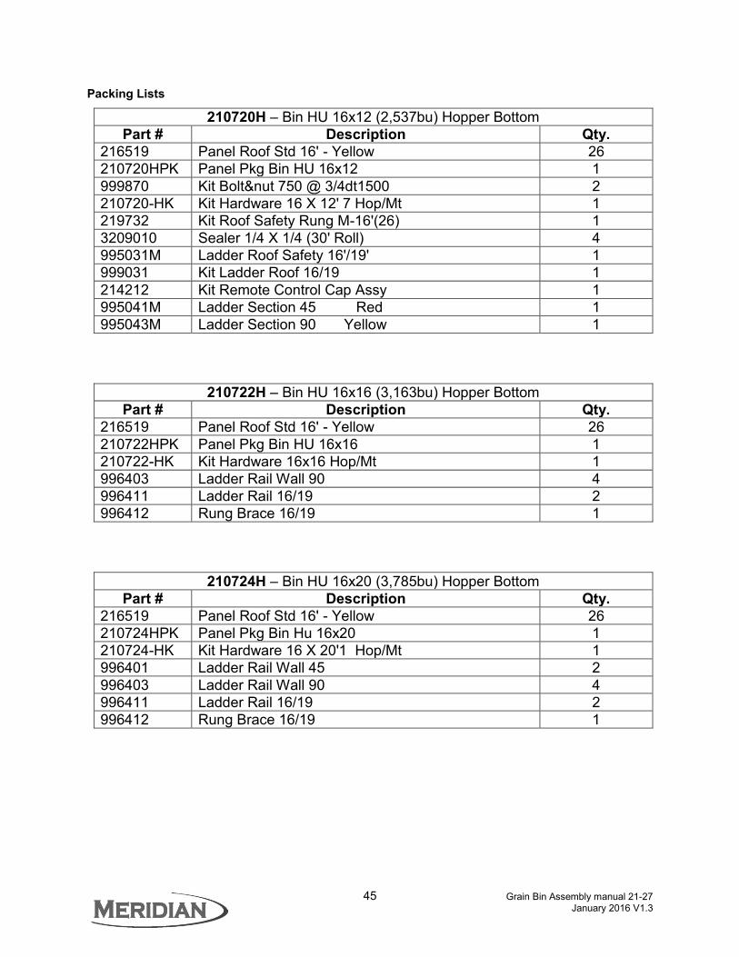
44 Grain Bin Assembly manual 21-27 January 2016 V1.3
Model 16 – Hopper Bottom Panel Layout
210720H 16’x12’-7” (2,537bu)
210722H 16’x16’-4” (3,163bu)
210724H 16’x20’-1” (3,785bu)
Ring Part GA Qty. Part GA Qty. Part GA Qty.
6 A 217284C 20 1 B 217285C 20 3 C 217284CDM 20 1
5 A 217284C 20 1 217086 18 2 B 217285C 20 3 217087 18 3 C 217284CDM 20 1
4 A 217284C 20 1 217086 18 2 217086 18 2 B 217285C 20 3 217087 18 3 217087 18 3 C 217284CDM 20 1
3 A 217086 18 2 217086 18 2 217088 16 2 B 217087 18 3 217087 18 3 217089 16 3
2 A 217086 18 2 217088 16 2 217090 14 2 B 217087 18 3 217089 16 3 217091 14 3
1 A 217114 12 6 217114 12 6 217114 12 6 B 217116 12 1 217116 12 1 217116 12 1
Note: Bottom Ring Is #1. Panel “C” Replaces a panel “A” in layout. Bushel capacities based on 1.25 cu. Ft. bushel. 5% allowance made for compaction.
B
45 Grain Bin Assembly manual 21-27 January 2016 V1.3
Packing Lists
210720H – Bin HU 16x12 (2,537bu) Hopper Bottom Part # Description Qty.
216519 Panel Roof Std 16' - Yellow 26 210720HPK Panel Pkg Bin HU 16x12 1 999870 Kit Bolt&nut 750 @ 3/4dt1500 2 210720-HK Kit Hardware 16 X 12' 7 Hop/Mt 1 219732 Kit Roof Safety Rung M-16'(26) 1 3209010 Sealer 1/4 X 1/4 (30' Roll) 4 995031M Ladder Roof Safety 16'/19' 1 999031 Kit Ladder Roof 16/19 1 214212 Kit Remote Control Cap Assy 1 995041M Ladder Section 45 Red 1 995043M Ladder Section 90 Yellow 1
210722H – Bin HU 16x16 (3,163bu) Hopper Bottom Part # Description Qty.
216519 Panel Roof Std 16' - Yellow 26 210722HPK Panel Pkg Bin HU 16x16 1 210722-HK Kit Hardware 16x16 Hop/Mt 1 996403 Ladder Rail Wall 90 4 996411 Ladder Rail 16/19 2 996412 Rung Brace 16/19 1
210724H – Bin HU 16x20 (3,785bu) Hopper Bottom Part # Description Qty.
216519 Panel Roof Std 16' - Yellow 26 210724HPK Panel Pkg Bin Hu 16x20 1 210724-HK Kit Hardware 16 X 20'1 Hop/Mt 1 996401 Ladder Rail Wall 45 2 996403 Ladder Rail Wall 90 4 996411 Ladder Rail 16/19 2 996412 Rung Brace 16/19 1

46 Grain Bin Assembly manual 21-27 January 2016 V1.3
Model 18 – Hopper Bottom Panel Layout
210708H 18’x16’-4” (3,896bu) 210718H 18’x18’-9” (4,400bu) Ring Part GA Qty. Part GA Qty.
5 A 217285C 20 4 217285C 20 4 C 217285CDM 20 1 217285CDM 20 1
4 A 217087 18 5 217087 18 5 3 A 217089 16 5 217089 16 5 2 A 217089 16 5 217089 16 5
1 A 217118 12 7 217093 12 5 B 217116 12 1
210728H 18’x20’-1” (4,688bu) 210738H 18’x23’-10” (5,479bu) Ring Part GA Qty. Part GA Qty.
7 A 217285C 20 4 C 217285CDM 20 1
6 A 217285C 20 4 217087 18 5 C 217285CDM 20 1
5 A 217087 18 5 217089 16 5 4 A 217089 16 5 217089 16 5 3 A 217089 16 5 217091 14 5 2 A 217091 14 5 217091 14 5
1 A 217118 12 7 217118 12 7 B 217116 12 1 217116 12 1
Note: Bottom Ring Is #1. Panel “C” Replaces a panel “A” in layout. Bushel capacities based on 1.25 cu. Ft. bushel. 5% allowance made for compaction.

47 Grain Bin Assembly manual 21-27 January 2016 V1.3
Packing Lists
210708H – Bin HU 18x16’-4” (3,896bu) Hopper Bottom Part # Description Qty.
217980 Panel Roof Std 18' - Brown 30 210708HPK Panel Pkg Bin Hu 18x16 1 999812 Kit Bolt&nut 500@1-1/4 Dt1500 1 999870 Kit Bolt&nut 750 @ 3/4dt1500 2 999801 Kit Bolt&nut 100 @ 3/4 Dt1500 1 210708-HK Kit Hardware 18'x16' 4 Hop/Mt 1 219733 Kit Roof Safety Rung M-19'(32) 1 995031M Ladder Roof Safety 16'/19' 1 999031 Kit Ladder Roof 16/19 1 214212 Kit Remote Control Cap Assy 1 995043M Ladder Section 90 Yellow 2
210718H – Bin HU 18x18’-9” (4,400bu) Hopper Bottom
Part # Description Qty. 210718HPK Panel Pkg Bin Hu 18x19 1 210718-HK Kit Hardware 18'x 18'-9 Hop/Mt 1 217980 Panel Roof Std 18' - Brown 30 996401 Ladder Rail Wall 45 2 996403 Ladder Rail Wall 90 4 996411 Ladder Rail 16/19 2 996412 Rung Brace 16/19 1
210728H – Bin HU 18x20’-1” (4,688bu) Hopper Bottom
Part # Description Qty. 217980 Panel Roof Std 18' - Brown 30 210728HPK Panel Pkg Bin HU 18x20 1 210728-HK Kit Hardware 18'x20'-1 Hop/Mt 1 996401 Ladder Rail Wall 45 2 996403 Ladder Rail Wall 90 4 996411 Ladder Rail 16/19 2 996412 Rung Brace 16/19 1
210738H – Bin HU 18x23’-10” (5,479bu) Hopper Bottom
Part # Description Qty. 217980 Panel Roof Std 18' - Brown 30 210738HPK Panel Pkg Bin HU 18x24 1 210738-HK Kit Hardware 18'x 23'-10 Ho/Mt 1 996401 Ladder Rail Wall 45 2 996402 Ladder Rail Wall 60 2 996403 Ladder Rail Wall 90 4 996411 Ladder Rail 16/19 2 996412 Rung Brace 16/19 1

48 Grain Bin Assembly manual 21-27 January 2016 V1.3
Model 19 – Hopper Bottom Panel Layout
210730H 19’x16’-4” (4,600bu)
210732H 19’x20’-1” (5,540bu)
210734H 19’x23’-10” (6,482bu)
Ring Part GA Qty. Part GA Qty. Part GA Qty. 7 A 217284C 20 7
C 217284CDM 20 1
6 A 217284C 20 7 217086 18 8 C 217284CDM 20 1
5 A 217284C 20 7 217086 18 8 217088 16 8 C 217284CDM 20 1
4 A 217086 18 8 217088 16 8 217088 16 8 3 A 217088 16 8 217088 16 8 217090 14 8 2 A 217088 16 8 217090 14 8 217096 12 8 1 A 217118 12 8 217118 12 8 217118 12 8
Note: Bottom Ring Is #1. Panel “C” Replaces a panel “B” in layout. Bushel capacities based on 1.25 cu. Ft. bushel. 5% allowance made for compaction.

49 Grain Bin Assembly manual 21-27 January 2016 V1.3
Packing Lists 210730H – Bin HU 19x16 4,600 bu. Hopper Bottom
Part # Description Qty. 217970 Panel Roof Std 19' - Red 32 216199 Stiffener Roof M-19' 2 210730-HK Kit Hardware 19 X 16'4 Hop/Mt 1 210730HPK Panel Pkg Bin Hu 19 x 16 1 996403 Ladder Rail Wall 90 4 996411 Ladder Rail 16/19 2 996412 Rung Brace 16/19 1
210732H – Bin HU 19x20 5,540 bu. Hopper Bottom Part # Description Qty.
217970 Panel Roof Std 19' - Red 32 216199 Stiffener Roof M-19' 2 210732HPK Panel Pkg Bin Hu 19x20 1 210732-HK Kit Hardware 19 X 20'1 Hop/Mt 1 996401 Ladder Rail Wall 45 2 996403 Ladder Rail Wall 90 4 996411 Ladder Rail 16/19 2 996412 Rung Brace 16/19 1
210734H – Bin HU 19x23 6,482 bu. Hopper Bottom Part # Description Qty.
217970 Panel Roof Std 19' – Red 32 216199 Stiffener Roof M-19' 2 210734HPK Panel Pkg Bin HU 19x23 1 210734-HK Kit Hardware 19 X 23'10 Hop/Mt 1 996403 Ladder Rail Wall 90 6 996411 Ladder Rail 16/19 2 996412 Rung Brace 16/19 1

50 Grain Bin Assembly manual 21-27 January 2016 V1.3
Model 22 – Hopper Bottom Panel Layout
210744H 22’x16’-4” (6,342bu)
210746H 22’x20’-1” (7,553bu)
210748H 22’x23’-10” (8,752bu)
Ring Part GA Qty. Part GA Qty. Part GA Qty. 7 A 217286C 20 5
A 217286CDM 20 1
6 A 217286C 20 5 217104 18 6 C 217286CDM 20 1
5 A 217286C 20 5 217104 18 6 217098 16 6 C 217286CDM 20 1
4 A 217104 18 6 217098 16 6 217100 14 6 3 A 217098 16 6 217100 14 6 217100 14 6 2 A 217100 14 6 217100 14 6 217110 12 6 1 A 217118 12 9 217118 12 9 217118 12 9
Note: Bottom Ring Is #1. Panel “C” Replaces a panel “A” in layout. Bushel capacities based on 1.25 cu. Ft. bushel. 5% allowance made for compaction.

51 Grain Bin Assembly manual 21-27 January 2016 V1.3
Packing Lists 210744H – Bin HU 22x16 6,342 bu. Hopper Bottom
Part # Description Qty. 216198 Stiffener Roof M22-27 2 216279 Panel Roof Std 22' - Blue 36 210744HPK Panel Pkg Bin HU 22x16 1 210744-HK Kit Hardware 22 X 16'4 Hop/Mt 1 996403 Ladder Rail Wall 90 4 996413 Ladder Rail 22' 2 996414 Rung Brace 22' 1
210746H – Bin HU 22x20 7,553 bu. Hopper Bottom Part # Description Qty.
216198 Stiffener Roof M22-27 2 216279 Panel Roof Std 22' - Blue 36 210746HPK Panel Pkg Bin Hu 22x20 1 210746-HK Kit Hardware 22'x 20' Hop/Mt 1 996401 Ladder Rail Wall 45 2 996403 Ladder Rail Wall 90 4 996413 Ladder Rail 22' 2 996414 Rung Brace 22' 1
210748H – Bin HU 22x23 8,752 bu. Hopper Bottom Part # Description Qty.
216198 Stiffener Roof M22-27 2 216279 Panel Roof Std 22' - Blue 36 210748HPK Panel Pkg Bin HU 22x23 1 210748-HK Kit Hardware 22 X 23'10 Hop/Mt 1 996403 Ladder Rail Wall 90 6 996413 Ladder Rail 22' 2 996414 Rung Brace 22' 1

52 Grain Bin Assembly manual 21-27 January 2016 V1.3
LADDERS Bolt Connection Details Letters listed on the assembly drawings where 2 pieces join indicate the type of connection. The connection types are illustrated below.

53 Grain Bin Assembly manual 21-27 January 2016 V1.3
12’ & 14’ Roof Ladder Assembly Part# 994030M
16’ & 19’ Roof Ladder Assembly Part# 994031M

54 Grain Bin Assembly manual 21-27 January 2016 V1.3
22’ Roof Ladder Assembly Part# 994032M
27’ Roof Ladder Assembly Part# 994033M

55 Grain Bin Assembly manual 21-27 January 2016 V1.3
90” Upper/Middle Safety Cage Assembly Part# 994035M
77” Lower Safety Cage Assembly Part# 994036M
56 Grain Bin Assembly manual 21-27 January 2016 V1.3
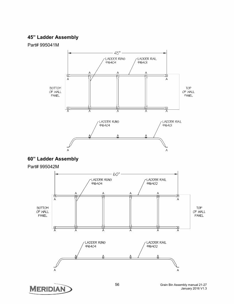
45” Ladder Assembly Part# 995041M
60” Ladder Assembly Part# 995042M

57 Grain Bin Assembly manual 21-27 January 2016 V1.3
90” Ladder Assembly Part# 995043M

58 Grain Bin Assembly manual 21-27 January 2016 V1.3
HOPPER MOUNTING INFORMATION The following information has been compiled to assist you in the manufacture of welded hopper cones for our various storage bins. The following diameters are taken from manufacturing drawings and indicate ideal situations. Because all bolt holes are 1/16" oversize, on a 16' dia. bin for example, with 156 bolts around the perimeter, stacking or spreading of wall sheets can affect the finish diameter.
Horizontal Bins Bin
Horizontal Approximate
Inside Diameter Approximate
Outside Diameter “A” “B” Circumference Bolts In Circumference
Model 12 3/4” 3.833” 460” 120 3.833” 529” 138
Model 16 190 1/4” 190 3/4” 3/4” 3.833” 598” 156 Model 18 219 5/8” 220 1/8” 3/4” 3.833” 690” 180 Model 19 234 1/4” 234 3/4” 3/4” 3.833” 736” 192 Model 22 263 1/2” 264” 3/4” 3.833” 828” 216 Model 27 322 1/8” 322 5/8” 3/4” 3.833” 1012” 264 Model 35 410 1/4” 410 3/4” 3/4” 3.833” 1288” 336
Vertical Bins Bin Vertical Approximate
Outside Diameter “A” “B” Circumference Bolts In Circumference
Model 12 146 3/8” 5/8” 3.833” 460” 120 Model 16 190 1/4” 5/8” 3.833” 598” 156 Model 22 263 7/16” 5/8” 3.833” 828” 216
On older vertical panel bins without base rings, the bottom lip must be cut off and 7/16 dia. holes drilled at 3.833" o.c. around the perimeter, 5/8" from the bottom of the panel.

59 Grain Bin Assembly manual 21-27 January 2016 V1.3
WARRANTY 1. The manufacturer guarantees its products against any defects in materials or workmanship for a
period of twelve (12) months from the date of purchase provided that the said products are set up according to its instructions and recommendations and provided- also that the said products are operated and used in proper conditions and according to its instructions and recommendations.
2. The manufacturer’s responsibility and obligations under this warranty shall be limited to
replacement of parts and shall not extend to parts, equipment or accessories that are component parts of manufacturer’s products but that are manufactured by other manufacturers. Those manufacturers’ warranty will apply to such parts, equipment or accessories. Any parts set up by reason of the application of this warranty shall be amenable to the terms of this warranty except that the period of twelve (12) months applicable to such parts shall be peremptory and that upon termination of the said period, warranty shall be null and void, for any purpose whatsoever with respect to said parts or any parts substituted to it before the termination of the said period of twelve (12) months.
3. This warranty shall not extend to loss and damage to content of the products, neither to property
or loss of revenue. Moreover it shall not extend to bodily injuries, including death, sustained by any person or animal.
4. The purchaser shall give notice to the manufacturer, without delay, of any damage or defects to
products that he may ascertain before they be set up, otherwise this warranty will not apply to such damage or defects.
5. Any modification or incorporation whatsoever made to products, except those authorized or recommended by the manufacturer, shall void this warranty; this warranty shall not apply to damages resulting from improper installation or erection of products by purchaser.
6. This warranty is the sole and only warranty and it is in lieu of any other warranty, express or implied, statutory or not.
7. Any claim under this warranty shall be notified in writing to the manufacturer’s head office within thirty (30) days from date of failure.
Specifications and descriptions are subject to change without notice.
Manufacturing Facility: BEHLEN Industries LP
927 Douglas Street Brandon, Manitoba Canada R7A 7B3
Phone: (204) 728-1188 Fax: (204) 725-4932
www.meridianmfg.com