mercmonitor version 6 - boten keuze · mercmonitor gateway models description ... alarm data check...
TRANSCRIPT

eng i
© 2
012
Mer
cury
Mar
ine
Mer
cMon
itor V
ersi
on 6
.090
-8M
0055
062
411

ii eng

eng iii
General Information
Basic Operation and Features..................................................... 1MercMonitor Gateway Models Description.................................. 3MercMonitor Gateway Protocol Acceptance Description.............8Connection to a Non‑SmartCraft Network................................. 10Automatic Engine Detection Feature......................................... 11Alarm Warnings with Descriptive Text....................................... 11Identifying and Using the Screen Categories............................ 18
Settings
Using the Light and Contrast Menu Options ............................. 20Setting the Units........................................................................ 27Available Screens...................................................................... 30Turning the Screens On.............................................................30Setting the Trim......................................................................... 53Setting the Tanks....................................................................... 58Setting the Alarms..................................................................... 67Setting the External Sensors..................................................... 73Setting the Offsets..................................................................... 80Setting the Clock........................................................................86Smart Tow Settings................................................................... 90Economy (ECO) Settings...........................................................93Setting the System.....................................................................98Reset Gauge to the Factory Default Settings.......................... 101Gateway Settings.....................................................................103Help Menu............................................................................... 108

iv eng
Propulsion Menu
Using Propulsion Screens ...................................................... 111Available Propulsion Screens ................................................. 111Troll Control Screen................................................................. 116Water Screen........................................................................... 119Oil Screen................................................................................ 119Peak Speed Screen................................................................. 120Fuel Pressure Screen.............................................................. 121RPM Synchronize Screen........................................................122Engine Location Fuel Use .......................................................122Double Screen......................................................................... 124Analog Tachometer Screen..................................................... 124Analog Speedometer Screen...................................................125Volts/Hours Screen.................................................................. 125Boost Pressure Screen............................................................ 126Trim Synchronize Screen........................................................ 126Trim Screen............................................................................. 127Trim/Tab Screen...................................................................... 127Smart Tow............................................................................... 128
Vessel Menu
Using the Vessel Screens........................................................139Available Vessel Screens........................................................ 140Economy (ECO) Screen.......................................................... 143Trip Data Screen......................................................................149Generator Screen.................................................................... 152Range Screen.......................................................................... 153Trim Screen............................................................................. 155Tanks....................................................................................... 156Tabs Screen............................................................................ 157GPS Screen............................................................................. 158To Waypoint Screen................................................................ 159Steering Screen....................................................................... 160Depth Screen........................................................................... 161

eng v
Full Screens
Full Screens Features and Options ........................................ 162Maintenance Screen................................................................ 167
Favorite Screens
Favorites Screen Features and Options.................................. 170
Alarms
Alarms Screen......................................................................... 176
Owners Assistance
Local Repair Service................................................................184Service Away from Home........................................................ 184Parts and Accessories Inquiries.............................................. 184Service Assistance.................................................................. 184Mercury Marine Service Offices...............................................185Ordering Literature...................................................................186

vi eng

GENERAL INFORMATION
eng 1
Basic Operation and FeaturesIMPORTANT: MercMonitor version 6.0 can be assimilated intomany different power package configurations; from a singleengine low horsepower outboard motor, to a multienginemultistation digital throttle and shift vessel. There may be somegauge features, displays, operations, and warnings that will notbe applicable for your power package. Some screens can beturned on, but will not show any changes to the display. See yourselling dealer for an explanation of what information your powerpackage can display.Power up: After the ignition is turned on, the front splash screenwill display the name of the gauge, the level of the gauge, andthe version of the software for approximately two seconds.Lights: Adjusts the brightness and contrast of the gauge.Buttons: The "MODE" button is used for selecting informationscreens. The "+" and "–" buttons are used for setting enginespeed for cruise control, launch control, and setting gaugecalibrations. To return to the previous screen, hold the "MODE"button down for three to five seconds.Cruise control: Sets and controls the speed of the engine forcruising.Launch control: Controls the speed of acceleration from idle tocruise speed.Engine Guardian System: Monitors the critical sensors on theengine for any early indication of problems. The system willrespond to a problem by reducing engine speed and alerting theoperator to a potentially damaging situation.Warning system: The system sounds the warning horn anddisplays the warning "AL" in the right corner of the "Main Menu"screen. The alarm screen will pop up, flashing a warning icon inthe middle of the screen and the "AL" in the upper right side ofthe screen. Press the "+" button to display the descriptive text.IMPORTANT: Optional sensors such as depth, fuel, paddlewheel, and steering angle, should always be connected to thestarboard engine when using SmartCraft gauges version 4.0 orlater.

GENERAL INFORMATION
2 eng
SYSTEM CHECK• The system check screen will appear after the front splash
screen. This option must be enabled to view it. Dependingon the installed power package, the system check screenwill display the overall condition of the battery and a fewother sensor conditions that are important for that powerpackage. The component description will be displayed onthe left side of the monitor, its corresponding icon will beoff‑center right, an icon in motion to the right will indicatewhat is being checked. When the component checks good,the icon in motion will change to "OK." If the system checkidentifies a problem, the icon in motion will change to awarning icon. You can bypass the system check by pressingthe "MODE" button to skip the check.
a - Componentdescription
b - Corresponding iconc - System check OKd - System check
warning icone - Icon in motion
• After the system check is completed and no problem isidentified, the monitor screen reverts to the last screen thatwas visible before the key switch was turned off. If aproblem was identified, the alarm screen will be displayed.Refer to Alarm Warnings with Descriptive Text.
MODE
Sys CheckBattery
[ SKIP ]
Oil PsiWater PsiWater Temp
OKOK!
30266
a
b
c
d
e
Maintenance

GENERAL INFORMATION
eng 3
PRODUCTS WITH EMISSIONS CONTROLAfter the ignition is turned on, the front splash screen will displaythe name of the gauge, the level of the gauge, and the version ofthe software for approximately two seconds. In the upperleft‑hand corner of the display, a small engine icon will also bevisible. The icon is a representation the power package hasemissions control onboard diagnostics, also known as OBD. Theicon will only be seen during the key up process unless a systemfault is detected. When an OBD fault is detected, the OBD iconwill be displayed in the upper left‑hand corner on all systemscreens.
30258
OBD icon
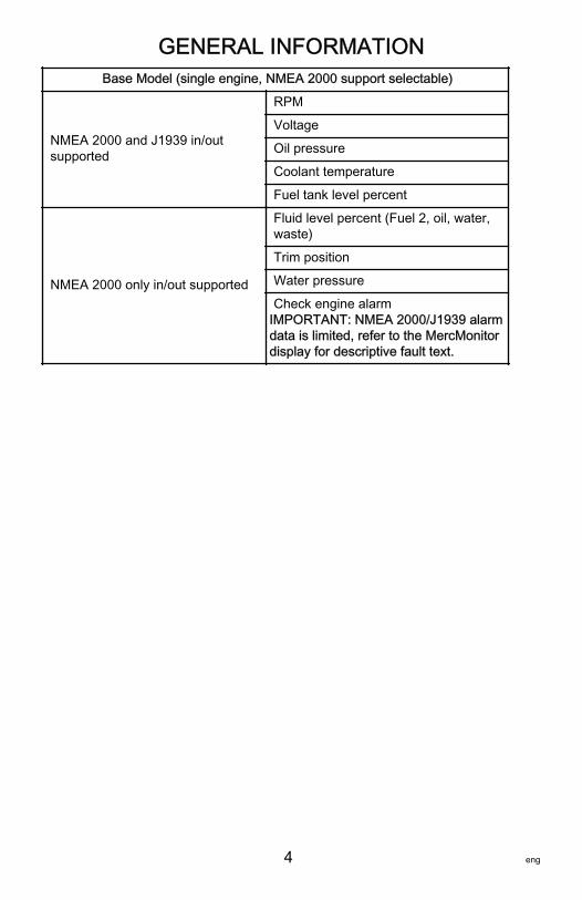
MercMonitor Gateway Models DescriptionThere are four MercMonitor gateway models available; basemodel with nine gateway features, RPM Smart Tow model with20 gateway features, Smart Tow Pro model with 25 gatewayfeatures (includes a GPS puck), and Gateway Premier modelwith 25 gateway features. Each model incorporates the use ofNMEA 20001. and J1939 software interface that allows orcontrols access to other programs.Each engine must have its own gateway monitor when using thebase or RPM Smart Tow models. Gateway Premier and SmartTow Pro models can communicate and provide NMEA 2000/J11939 with four engines or less. Gateway Premier and SmartTow Pro models screen will only display single engine data.Premier does not include Smart Tow Pro control capabilities.
1. NMEA 2000 pending certification.
GENERAL INFORMATION
4 eng
Base Model (single engine, NMEA 2000 support selectable)
NMEA 2000 and J1939 in/outsupported
RPM
Voltage
Oil pressure
Coolant temperature
Fuel tank level percent
NMEA 2000 only in/out supported
Fluid level percent (Fuel 2, oil, water,waste)
Trim position
Water pressure
Check engine alarmIMPORTANT: NMEA 2000/J1939 alarmdata is limited, refer to the MercMonitordisplay for descriptive fault text.

GENERAL INFORMATION
eng 5
RPM Smart Tow Model (single engine, NMEA 2000 support selectable)
NMEA 2000 and J1939 in/outsupported
RPM
Voltage
Oil pressure
Coolant temperature
Fuel tank level percent
Fuel flow
Engine hours
Boost pressure
Oil temperature
NMEA 2000 only in/out supported
Fluid level percent (Fuel 2, oil,water, waste)
Trim position
Water pressure
Check engine alarmIMPORTANT: NMEA 2000/J1939alarm data is limited, refer to theMercMonitor display for descriptivefault text.
Tabs
GPS speed/COG/latitude, longitude(in only)
Depth
Seawater temperature
Paddle wheel speed
Pitot speed

GENERAL INFORMATION
6 eng
Smart Tow Pro Model with GPS puck (four engine or less, NMEA 2000support selectable)
NMEA 2000 and J1939 in/outsupported
RPM
Voltage
Oil pressure
Coolant temperature
Fuel tank level percent
Fuel flow
Engine hours
Boost pressure
Oil temperature
NMEA 2000 in/out supported (only)
Fluid level percent (Fuel 2, oil,water, waste)
Trim position
Water pressure
Check engine alarmIMPORTANT: NMEA 2000/J1939alarm data is limited, refer to theMercMonitor display for descriptivefault text.
Tabs
GPS speed/COG/latitude, longitude(in only)
Depth
Seawater temperature
Paddle wheel speed
Pitot speed
Rudder angle
Gear pressure (CMD diesel)
Gear temperature (CMD diesel)
Fuel pressure
Capacity (English or metric)

GENERAL INFORMATION
eng 7
Gateway Premier (four engine or less, NMEA 2000 support selectable)(includes RPM Smart Tow)
NMEA 2000 and J1939 in/outsupported
RPM
Voltage
Oil pressure
Coolant temperature
Fuel tank level percent
Fuel flow
Engine hours
Boost pressure
Oil temperature
NMEA 2000 in/out supported (only)
Fluid level percent (Fuel 2, oil,water, waste)
Trim position
Water pressure
Check engine alarmIMPORTANT: NMEA 2000/J1939alarm data is limited, refer to theMercMonitor display for descriptivefault text.
Tabs
GPS speed/COG/latitude, longitude(in only)
Depth
Seawater temperature
Paddle wheel speed
Pitot speed
Rudder angle
Gear pressure (CMD diesel)
Gear temperature (CMD diesel)
Fuel pressure
Capacity (English or metric)

GENERAL INFORMATION
8 eng
MercMonitor Gateway Protocol AcceptanceDescriptionGateway is a software interface that allows or controls access toother programs through a NMEA 2000 or J1939 protocol; abackbone for communication to share information. The softwareis capable of transmitting (TX) information to, and receiving (RX)information from various parameter group number (PGN)products.
Gateway Modes
Transmit (TX) Receive (RX)
Transmits engine data to NMEA 2000/J1939compatible display devices.
Receives data from NMEA2000/J1939 compatibleengines.
Base and RPM Smart Tow models require oneMercMonitor per engine.
Each engine requires itsown MercMonitorregardless of the model(base, RPM Smart Tow,Smart Tow Pro, GatewayPremier)
Gateway Premier and Smart Tow Pro modelsrequire only one MercMonitor per vessel totransmit multiengine data to multifunctiondisplays (MFD) through the NMEA 2000/J1939protocol.
The MercMonitor will display one engine onlyregardless of the model (base, RPM SmartTow, Smart Tow Pro, Gateway Premier).
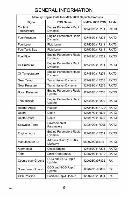
Mercury Engine Data to NMEA 2000 Capable Products
Signal PGN Name NMEA 2000 PGN Mode
Rated RPM Engine Parameter Static 127498/0x1F20A RX/TX
Coolant Pressure Engine Parameters RapidDynamic 127489/0x1F201 RX/TX
Speed Over Water Speed 128259/0x1F503 RX/TX
RPM Engine Parameters RapidUpdate 127488/0x1F200 RX/TX
Voltage Engine Parameters RapidDynamic 127489/0x1F201 RX/TX
GENERAL INFORMATION
eng 9
Mercury Engine Data to NMEA 2000 Capable Products
Signal PGN Name NMEA 2000 PGN Mode
CoolantTemperature
Engine Parameters RapidDynamic 127489/0x1F201 RX/TX
Fuel Pressure Engine Parameters RapidDynamic 127489/0x1F201 RX/TX
Fuel Level Fluid Level 127505/0x1F211 RX/TX
Fuel Tank Size Fluid Level 127505/0x1F211 RX/TX
Fuel Flow Engine Parameters RapidDynamic 127489/0x1F201 RX/TX
Oil Pressure Engine Parameters RapidDynamic 127489/0x1F201 RX/TX
Oil Temperature Engine Parameters RapidDynamic 127489/0x1F201 RX/TX
Gear Temp Transmission Dynamic 127493/0x1F205 RX/TX
Gear Pressure Transmission Dynamic 127493/0x1F205 RX/TX
Boost Pressure Engine Parameters RapidUpdate 127488/0x1F200 RX/TX
Trim position Engine Parameters RapidUpdate 127488/0x1F200 RX/TX
Rudder Angle Rudder 127245/0x1F10D RX/TX
Depth Depth 128267/0x1F50B RX/TX
Depth Offset Depth 128267/0x1F50B RX/TX
Seawater Temp EnvironmentalParameters 130310/0x1FD06 RX/TX
Engine hours Engine Parameters RapidDynamic 127489/0x1F201 RX/TX
Manufacturer ID Address Claim (0 x 90 =Mercury) 060928/0xEE00 RX/TX
Alarm data Check Engine 127489/0x1F201 RX/TX
Tabs Small Craft Status 130576/0x1FE10 RX/TX
Course over Ground COG and SOG RapidUpdate 129026/0x9F802 RX
Speed over Ground COG and SOG RapidUpdate 129026/0x9F802 RX
GPS Position Position Rapid Update 129025/0x1F801 RX

GENERAL INFORMATION
10 eng
Mercury Engine Data to NMEA 2000 Capable Products
Signal PGN Name NMEA 2000 PGN Mode
Battery Battery Status 127508/0x1F214 RX/TX
Mercury Engine Data to J1939 Capable Products
Signal PGN Name J1939 PGN Mode
RPM Electronic EngineController #1 61444/0xF004 TX
Voltage Vehicle Electrical Power 65271/0xFEF7 TX
Coolant Temperature Engine Temperature #1 65262/0xFEEE TX
Fuel Level Dash Display 65276/0xFEFC TX
Fuel Consumption Fuel Economy (Liquid) 65266/0xFEF2 TX
Fuel Flow Fuel Economy (Liquid) 65266/0xFEF2 TX
Oil Pressure Engine Fluid Level/Press#1 65263/0xFEEF TX
Boost Pressure Inlet/Exhaust Conditions 65270/0xFEF6 TX
Engine hours Total Engine Hours 65253/0xFEE5 TX
Manufacturer ID Address Claim (0 x 90 =Mercury) 61182/0xEEFE TX
Alarm data(Diagnostic messagesupported)
Check Engine 65226/0xFECA TX
Line‑Line AC RMSVolt Generator Set Average 65030/0xFE06 RX/TX
AC RMS Frequency Generator Set Average 65030/0xFE06 RX/TX
Connection to a Non‑SmartCraft NetworkThe use of the MercMonitor on a non‑SmartCraft networkapplication requires the MercMonitor gateway set to "Receive."Failure to set the gateway to "Receive" will cause numerousfaults to appear that cannot be resolved. Changing the gatewayto "Receive" will clear the faults. The menu path to set thegateway to "Receive" is: "Main Menu," > "Settings," >"Gateway," > "Gateway."

GENERAL INFORMATION
eng 11
Automatic Engine Detection FeatureThe SmartCraft monitor has an automatic engine detectionfeature. This feature automatically detects which engine type isused and configures the gauge to match that engine type.The first power up of the gauge, or after a reset all to factorydefault 2, the gauge will display "AUTODETECT." Press the"MODE" button to start the automatic engine detection featureand the gauge will determine the engine type. This will preset thedata monitoring screens to make the initial setup easier.
MODE35915
AUTODETECT
ENGINE SMARTSCREENPRESS MODE TO START
If the gauge shows a warning of "NO STARBOARD ENGINE" or"MULTIPLE STARBOARD ENGINES," the engine location (portand starboard) must be selected by an authorized dealerequipped with the computer diagnostic system (CDS) tool.
Alarm Warnings with Descriptive TextIMPORTANT: Alarm warnings and descriptive fault text are onlyavailable on the MercMonitor screen. NMEA 2000/J1939gateway is limited to seven alarm functions.

GENERAL INFORMATION
12 eng
NOTE: Descriptive text alarm warning screens are displayed withGen I (2007) engines and newer.
a - Flashing "AL" alarmb - Flashing warning iconc - "+" button to show
descriptive text
When a problem is detected, the "AL" alarm appears and apop‑up window with the alarm location and fault number will bedisplayed. The faulty component or warning is described in thetext. Press the "+" button for more information. This screen givesa detailed description of the fault text. Press the "+" button toview the required corrective action.The alarm message will stay displayed until the "–" button ispressed. This action will exit the warning screen. If there aremultiple alarms, press the "MODE" button to view the nextwarning display.If a problem can cause immediate engine damage, the EngineGuardian System will respond to the problem by limiting enginepower. Immediately reduce the throttle speed to idle and refer tothe warning messages. If the "MODE" button is pressed todisplay a different screen, the flashing alarm signal "AL" willappear in the upper right corner to indicate there still is aproblem. Refer to the appropriate service manual for furtherexplanation of the problem and the correct action to take.
MODE
Alarms AL
35736
![EXIT] [SHOW]
a
b
c
!
System

GENERAL INFORMATION
eng 13
VIEWING DESCRIPTIVE TEXT1. When a problem is detected, the "AL" alarm will flash on the
display and a pop‑up window displays the system where thefault is located, the fault code, and what component isidentified as a problem.
a - System fault andcode
b - Component
2. Press the "+" button to view the descriptive warning text.The identified component expands to show additional textdescribing the fault.
a - System fault andcode
b - Additional textdescribing the fault
MODE
Alarms AL
35737
[EXIT] [MORE]
a
b
[NEXT]
STBD Sys Fault 57<Ignition>
!
MODE
Alarms AL
35738
[EXIT] [ACTION]
a
b
[NEXT]
STBD Sys Fault 57<Ignition coil is not working properly>
!
GENERAL INFORMATION
14 eng
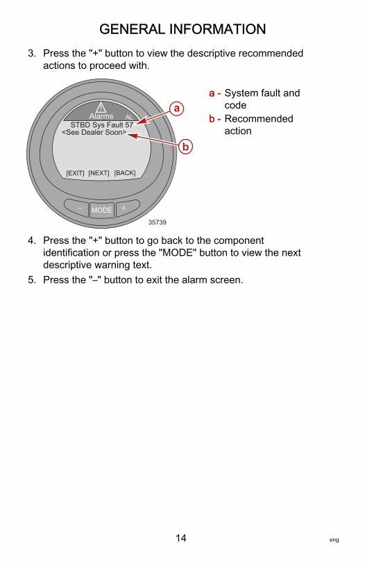
3. Press the "+" button to view the descriptive recommendedactions to proceed with.
a - System fault andcode
b - Recommendedaction
4. Press the "+" button to go back to the componentidentification or press the "MODE" button to view the nextdescriptive warning text.
5. Press the "–" button to exit the alarm screen.
MODE
Alarms AL
35739
[EXIT] [BACK]
a
b
[NEXT]
STBD Sys Fault 57<See Dealer Soon>
!
GENERAL INFORMATION
eng 15
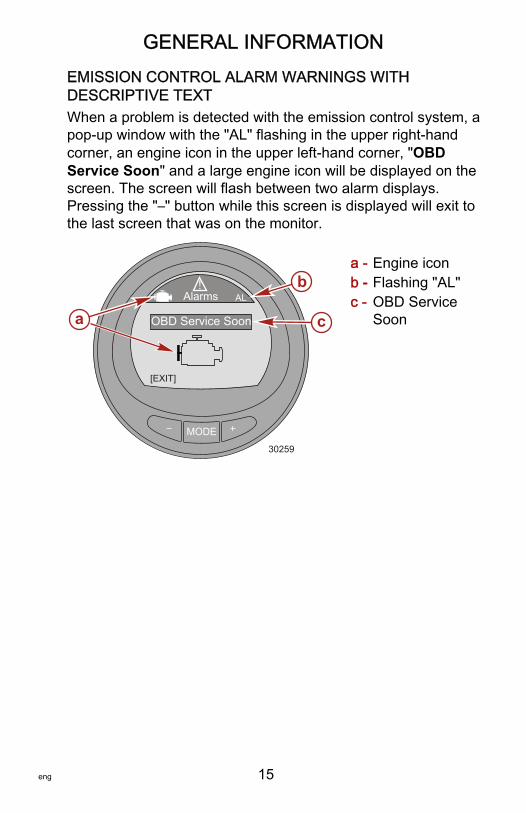
EMISSION CONTROL ALARM WARNINGS WITHDESCRIPTIVE TEXTWhen a problem is detected with the emission control system, apop‑up window with the "AL" flashing in the upper right‑handcorner, an engine icon in the upper left‑hand corner, "OBDService Soon" and a large engine icon will be displayed on thescreen. The screen will flash between two alarm displays.Pressing the "–" button while this screen is displayed will exit tothe last screen that was on the monitor.
a - Engine iconb - Flashing "AL"c - OBD Service
Soon
MODE
Alarms AL
30259
[EXIT]
!
OBD Service Soona
b
c

GENERAL INFORMATION
16 eng
1. The second flashing alarm display shows the engine OBDicon, the flashing "AL," and warning icon. Press the "+"button for more information.
a - OBD iconb - Flashing "AL" alarmc - Flashing warning icond - "+" button to show descriptive text
MODE
Alarms AL
30260
![EXIT] [SHOW]
b
c
d
!
Systema

GENERAL INFORMATION
eng 17
2. The screen displays the engine location, the system faultcode number, and a description of the faulty component.Press the "+" button for more information.
a - Engine locationb - Fault codec - Fault description
3. A detailed description of the fault component is explained.Press the "+" button for information on a corrective action.
a - Detaileddescription ofthe faultcomponent
b - "+" button toshow correctiveaction
MODE
Alarms AL
30261
[EXIT] [MORE]
bc
!
STB Sys Fault 115a<Engine Sensor>
MODE
Alarms AL
30262
[EXIT] [ACTION]
!
STB Sys Fault 115a <Exhaust Oxygen
Sensor is not workingproperly>
b
GENERAL INFORMATION
18 eng
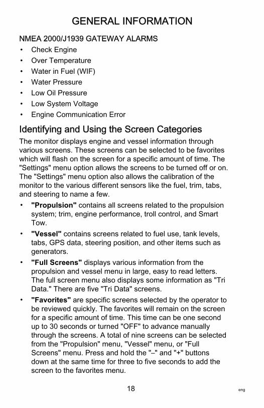
NMEA 2000/J1939 GATEWAY ALARMS• Check Engine• Over Temperature• Water in Fuel (WIF)• Water Pressure• Low Oil Pressure• Low System Voltage• Engine Communication Error
Identifying and Using the Screen CategoriesThe monitor displays engine and vessel information throughvarious screens. These screens can be selected to be favoriteswhich will flash on the screen for a specific amount of time. The"Settings" menu option allows the screens to be turned off or on.The "Settings" menu option also allows the calibration of themonitor to the various different sensors like the fuel, trim, tabs,and steering to name a few.• "Propulsion" contains all screens related to the propulsion
system; trim, engine performance, troll control, and SmartTow.
• "Vessel" contains screens related to fuel use, tank levels,tabs, GPS data, steering position, and other items such asgenerators.
• "Full Screens" displays various information from thepropulsion and vessel menu in large, easy to read letters.The full screen menu also displays some information as "TriData." There are five "Tri Data" screens.
• "Favorites" are specific screens selected by the operator tobe reviewed quickly. The favorites will remain on the screenfor a specific amount of time. This time can be one secondup to 30 seconds or turned "OFF" to advance manuallythrough the screens. A total of nine screens can be selectedfrom the "Propulsion" menu, "Vessel" menu, or "FullScreens" menu. Press and hold the "–" and "+" buttonsdown at the same time for three to five seconds to add thescreen to the favorites menu.

GENERAL INFORMATION
eng 19
• "Alarms" displays information on the location, identifies,and advises a corrective action to take for all warningalarms. While in the "Alarms" category, press the "+" buttonfor more detailed descriptive text about the fault. Press the"+" button again to review the recommended correctiveaction to take. Press the "MODE" button to review the nextfault, or press the "–" button to exit the "Alarms" descriptivetext screen.
• "Settings" allows the user to turn on and off screens, selecta type of measurement (knots, kilometers, miles), select ascreen color, adjust the contrast and brightness of thescreen, select a digital or analog clock display, adjust andcorrect various different sensor parameters (tanks, trim,tabs), activate a GPS interface with the gauge, give thegauge a specific name (up to 14 characters), and reset thegauge to the factory default settings.

SETTINGS
20 eng
Using the Light and Contrast Menu Options1. While in the "Main Menu," press the "–" or "+" button to
highlight the "Settings" menu.2. Press the "MODE" button to edit the "Light/Contrast" menu.
CONTRAST1. Press the "MODE" button to edit the "Contrast" option.2. Press the "–" or "+" button to edit the contrast level of the
monitor screen.
MODE35797
BrightnessDisplay Color
Color SyncButton Color
[DOWN] [SAVE]
ContrastLight/Contrast
54100
BlueWhite
No[ UP ]
3. Press the "MODE" button to save the contrast setting.4. To exit the "Light/Contrast" menu, press the "–" or "+" button
to highlight the "Exit" option. Press the "MODE" button toexit the "Light/Contrast" menu.
BRIGHTNESS1. Press the "–" button to highlight the "Brightness" option.2. Press the "MODE" button to edit the brightness of the
monitor screen.

SETTINGS
eng 21
3. Press the "–" or "+" button to change the brightness of themonitor screen.
MODE35800
Display ColorButton Color
[DOWN] [EDIT]
ContrastLight/Contrast
54
[ UP ]
100Blue
White
Brightness
Color Sync No
4. Press the "MODE" button to save the brightness setting.5. To exit the "Light/Contrast" menu, press the "–" or "+" button
to highlight the "Exit" option. Press the "MODE" button toexit the "Light/Contrast" menu.
DISPLAY COLORThe display backlighting color can be changed to red, blue,green, white, yellow, purple, and ice blue. All the monitor colorscan be selected to be displayed for approximately 15 secondseach. After the 15 seconds, the color will fade and change intothe next color. This is referred to as the color "Wave."1. Press the "–" button to highlight the "Display Color" option.2. Press the "MODE" button to edit the display color of the
monitor screen.

SETTINGS
22 eng
3. Press the "–" or "+" button to select a color, or select "Wave"for the color of the monitor screen.
MODE35804
Button Color
[DOWN] [EDIT]
ContrastLight/Contrast
54
[ UP ]
100Blue
White
BrightnessDisplay Color
Color Sync No
4. Press the "MODE" button to save the display color setting.5. To exit the "Light/Contrast" menu, press the "–" or "+" button
to highlight the "Exit" option. Press the "MODE" button toexit the "Light/Contrast" menu.
BUTTON COLORThe "–," "+," and "MODE" button light color can be changed tored, blue, green, white, yellow, purple, and ice blue. All of thebutton colors can be selected to be displayed for approximately15 seconds each. After the 15 seconds, the color will fade andchange into the next color. This is referred to as the color"Wave."1. Press the "–" button to highlight the "Button Color" option.2. Press the "MODE" button to edit the button colors.

SETTINGS
eng 23
3. Press the "–" or "+" button to select a color, or select "Wave"for the color of the buttons.
MODE35806
Button Color
[DOWN] [EDIT]
ContrastLight/Contrast
54
[ UP ]
100Blue
White
BrightnessDisplay Color
Color Sync No
4. Press the "MODE" button to save the button color setting.5. To exit the "Light/Contrast" menu, press the "–" or "+" button
to highlight the "Exit" option. Press the "MODE" button toexit the "Light/Contrast" menu.
COLOR SYNCThe "Color Sync" feature selects the same color for the backlightand the buttons. Turning the color synchronize on ("Yes"), turnsthe "Button Color" control feature off.1. Press the "–" button to highlight the "Color Sync" option.
SETTINGS
24 eng
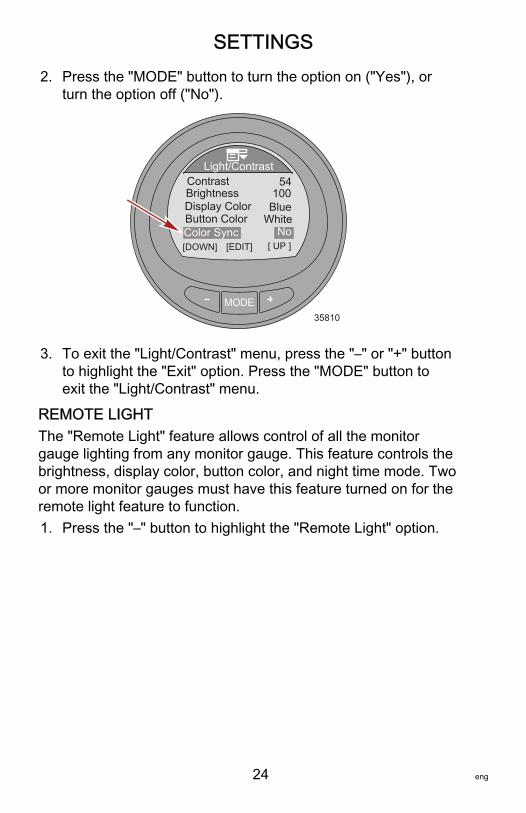
2. Press the "MODE" button to turn the option on ("Yes"), orturn the option off ("No").
MODE35810
Button Color
[DOWN] [EDIT]
ContrastLight/Contrast
54
[ UP ]
100Blue
White
BrightnessDisplay Color
Color Sync No
3. To exit the "Light/Contrast" menu, press the "–" or "+" buttonto highlight the "Exit" option. Press the "MODE" button toexit the "Light/Contrast" menu.
REMOTE LIGHTThe "Remote Light" feature allows control of all the monitorgauge lighting from any monitor gauge. This feature controls thebrightness, display color, button color, and night time mode. Twoor more monitor gauges must have this feature turned on for theremote light feature to function.1. Press the "–" button to highlight the "Remote Light" option.

SETTINGS
eng 25
2. Press the "MODE" button to turn the option on ("Yes"), orturn the option off ("No").
MODE36307
Exit[DOWN] [EDIT]
Remote Light
Light/ContrastYes
[ UP ]
YesNoNo
Remote ContrastNight Time Mode
Color Sync
3. To exit the "Light/Contrast" menu, press the "–" or "+" buttonto highlight the "Exit" option. Press the "MODE" button toexit the "Light/Contrast" menu.
REMOTE CONTRASTThe "Remote Contrast" feature allows control of the monitorgauge contrast from any monitor gauge. This feature controlsonly the contrast. Two or more monitor gauges must have thisfeature turned on for the remote contrast feature to function.1. Press the "–" button to highlight the "Remote Contrast"
option.

SETTINGS
26 eng
2. Press the "MODE" button to turn the option on ("Yes"), orturn the option off ("No").
MODE35812
[DOWN] [EDIT]
Light/Contrast
[ UP ]Exit
Remote LightYesYes
NoRemote ContrastNight Time Mode
Color Sync
No
3. To exit the "Light/Contrast" menu, press the "–" or "+" buttonto highlight the "Exit" option. Press the "MODE" button toexit the "Light/Contrast" menu.
NIGHT TIME MODE"Night Time Mode" darkens the monitor screen, turning theletters and numbers to the color selected. This mode whenturned on, significantly decreases the amount of backlighting onthe gauge.1. Press the "–" button to highlight the "Night Time Mode"
option.

SETTINGS
eng 27
2. Press the "MODE" button to turn the option on ("Yes"), orturn the option off ("No"). A third option automatically("AUTO") selects the "Night Time Mode" when the ambientlight conditions fade.
MODE35813
Light/ContrastColor Sync
[DOWN] [EDIT] [ UP ]
WhiteYesRemote Light
Remote Contrast No
ExitNight Time Mode Yes
3. To exit the "Light/Contrast" menu, press the "–" or "+" buttonto highlight the "Exit" option. Press the "MODE" button toexit the "Light/Contrast" menu.
Setting the UnitsThe "Units" menu option changes the display units ofmeasurement to English ("Eng") or metric ("Met"), and the speeddisplay to miles per hour ("MPH"), kilometers per hour ("KMH"),or knots ("KN").1. While in the "Main Menu," press the "–" or "+" button to
highlight the "Settings" menu.
SETTINGS
28 eng
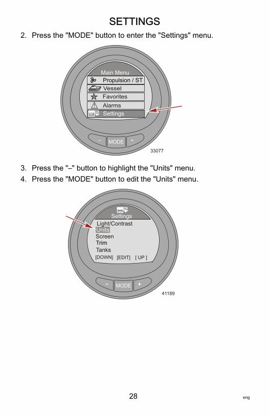
2. Press the "MODE" button to enter the "Settings" menu.
MODE
Main MenuPropulsion / ST
FavoritesVessel
33077
SettingsAlarms!
3. Press the "–" button to highlight the "Units" menu.4. Press the "MODE" button to edit the "Units" menu.
MODE
Settings
41189
Screen
TanksTrim
[DOWN] [EDIT]
Light/ContrastUnits
[ UP ]
SETTINGS
eng 29
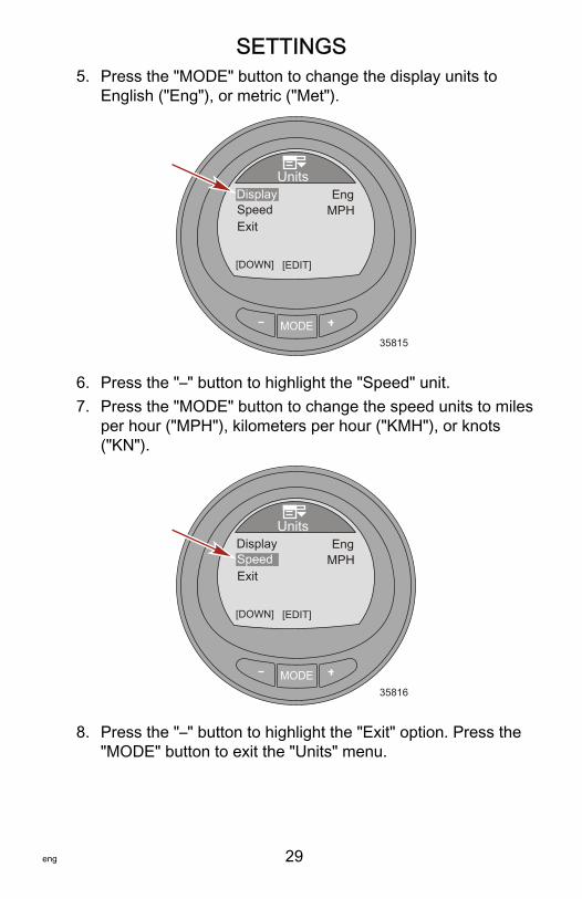
5. Press the "MODE" button to change the display units toEnglish ("Eng"), or metric ("Met").
MODE35815
ExitSpeed
[DOWN] [EDIT]
UnitsDisplay Eng
MPH
6. Press the "–" button to highlight the "Speed" unit.7. Press the "MODE" button to change the speed units to miles
per hour ("MPH"), kilometers per hour ("KMH"), or knots("KN").
MODE35816
ExitSpeed
[DOWN] [EDIT]
UnitsDisplay Eng
MPH
8. Press the "–" button to highlight the "Exit" option. Press the"MODE" button to exit the "Units" menu.

SETTINGS
30 eng
Available ScreensWithin the "Screens" menu, screens can be turned off or on. The"Full Screens" submenu has nine full screens that can be turnedoff or on. Additionally within the "Full Screens" submenu, thereare up to five "Tri Data" screens and "Double Screen" that areuser modified. Screens that are turned off or on also have adirect relation to the various screens in the propulsion and vesselmenus, and are dependant on the power package installed thatsupports the different sensors.
• Full screens• Tri Data• Double screen• ECO screen• System check• Analog RPM• Analog speed• Trim and RPM• Peak speed• Water information• Oil information• Fuel pressure• Volts and hours
• Fuel used• Depth• Steering position• Boost pressure• Tabs• GPS data• Waypoint• Troll control• Smart Tow• Generator• Screen synchronize• Favorite slides
Turning the Screens OnFULL SCREENS OPTIONS1. While in the "Main Menu," press the "–" or "+" button to
highlight the "Settings" menu.

SETTINGS
eng 31
2. Press the "MODE" button to enter the "Settings" menu.
MODE30267
Settings
Main Menu
FavoritesVessel
Alarms!
Propulsion / ST
3. Press the "–" button to highlight the "Screens" menu.4. Press the "MODE" button to edit the "Screens" menu.
MODE
Settings
42175
TanksTrim
[DOWN] [EDIT]
Light/ContrastUnits
[ UP ]
Screens

SETTINGS
32 eng
5. Press the "MODE" button to edit the "Full Screens" menu.
MODE
Screens
30268
Tri Data
ECO Screen
[DOWN] [EDIT]
Full Screens
Double Screen
[ UP ]Sys Check No
No
6. Press the "MODE" button to turn the "Speed" option on("Yes") or off ("No").
MODE30269
[DOWN] [EDIT]
Full Screens
Air TempDepth
YesNo
NoCoolant TempClock
Speed
No
No
7. Press the "–" button to highlight the "Depth" option.
SETTINGS
eng 33
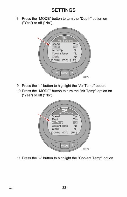
8. Press the "MODE" button to turn the "Depth" option on("Yes") or off ("No").
MODE30270
[DOWN] [EDIT]
Full Screens
Air TempDepth
Yes
NoCoolant TempClock
Speed
No
No
Yes
[ UP ]
9. Press the "–" button to highlight the "Air Temp" option.10.Press the "MODE" button to turn the "Air Temp" option on
("Yes") or off ("No").
MODE30272
[DOWN] [ UP ]
Full Screens
Air TempDepth
Yes
NoCoolant TempClock
Speed
No
YesYes
[EDIT]
11.Press the "–" button to highlight the "Coolant Temp" option.

SETTINGS
34 eng
12.Press the "MODE" button to turn the "Coolant Temp" optionon ("Yes") or off ("No").
MODE30273
[DOWN] [ UP ]
Full Screens
Air TempDepth
Yes
NoCoolant TempClock
Speed
No
YesYes
[EDIT]
13.Press the "–" button to highlight the "Clock" option.14.Press the "MODE" button to edit the "Clock" option to off
("No"). Press the "MODE" button again to change the clockto an "Analog" display, or press the "MODE" button again tochange the display to "Digital."
MODE30274
[DOWN] [ UP ]
Full Screens
Air TempDepth
Yes
NoCoolant TempClock
Speed
No
YesYes
[EDIT]
15.Press the "–" button to highlight the "Oil Temp" option.
SETTINGS
eng 35
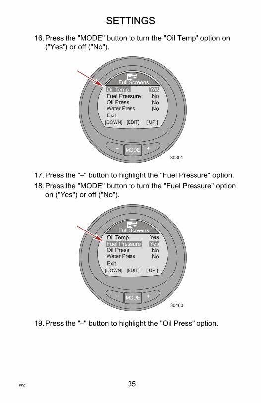
16.Press the "MODE" button to turn the "Oil Temp" option on("Yes") or off ("No").
MODE30301
[DOWN] [EDIT]
Full Screens
Exit
Oil Temp Yes
Water PressOil PressFuel Pressure No
[ UP ]
NoNo
17.Press the "–" button to highlight the "Fuel Pressure" option.18.Press the "MODE" button to turn the "Fuel Pressure" option
on ("Yes") or off ("No").
MODE30460
[DOWN] [EDIT]
Full Screens
Exit
Oil Temp Yes
Water PressOil PressFuel Pressure
[ UP ]
NoNo
Yes
19.Press the "–" button to highlight the "Oil Press" option.
SETTINGS
36 eng
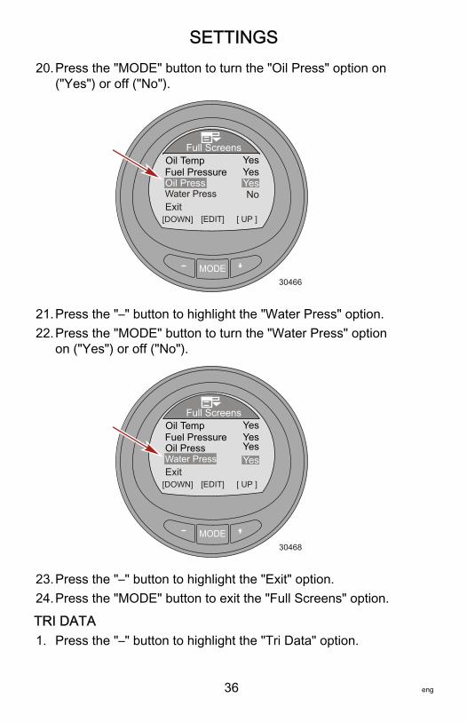
20.Press the "MODE" button to turn the "Oil Press" option on("Yes") or off ("No").
MODE30466
[DOWN] [EDIT]
Full Screens
Exit
Oil Temp Yes
Water PressOil PressFuel Pressure
[ UP ]
No
YesYes
21.Press the "–" button to highlight the "Water Press" option.22.Press the "MODE" button to turn the "Water Press" option
on ("Yes") or off ("No").
MODE30468
[DOWN] [EDIT]
Full Screens
Exit
Oil Temp Yes
Water PressOil PressFuel Pressure
[ UP ]
Yes
YesYes
23.Press the "–" button to highlight the "Exit" option.24.Press the "MODE" button to exit the "Full Screens" option.
TRI DATA1. Press the "–" button to highlight the "Tri Data" option.

SETTINGS
eng 37
2. Press the "MODE" button to edit the "Tri Data" screens.
MODE
Screens
30473
Tri Data
ECO Screen
[DOWN] [EDIT]
Full Screens
Double Screen
[ UP ]Sys Check No
No
3. The first "Tri Data" screen is turned on ("Yes") by default. Toedit "Screen 1," press the "MODE" button twice.
MODE36398
[DOWN] [EDIT]
Tri DataYesScreen 1
Screen 2Screen 3
Screen 5Screen 4
NoNo
NoNo
4. Press the "MODE" button to edit the "Top" screen option.5. Press the "–" or "+" button to change the "Top" data
information.

SETTINGS
38 eng
NOTE: The information available for the "Top," "Left," and"Right" "Tri Data" is: "Hours," "Clock," "Depth," "Fuel," "RPM,""Speed," "Coolant Temp," "Oil Temp," "Seatemp," "WaterPress," "Oil Press," "Trim," "Fuel Flow," and "Battery."
MODE36402
[DOWN] [EDIT]
Tri DataClockTop
LeftRightExit
DepthBattery
[ UP ]
6. Press the "MODE" button to exit the "Top" screen dataoption.
7. Press the "–" button to highlight the "Left" screen option.8. Press the "MODE" button to edit the "Left" screen option.9. Press the "–" or "+" button to change the left side data
information.
MODE36403
[DOWN] [EDIT]
Tri DataClockTop
LeftRightExit
DepthBattery
[ UP ]

SETTINGS
eng 39
10.Press the "MODE" button to exit the "Left" screen dataoption.
11.Press the "–" button to highlight the "Right" screen option.12.Press the "MODE" button to edit the "Right" screen option.13.Press the "–" or "+" button to change the right side data
information.
MODE36405
[DOWN] [EDIT]
Tri DataClockTop
LeftRightExit
DepthBattery
[ UP ]
14.Press the "MODE" button to exit the "Right" screen dataoption.
15.Press the "–" button to highlight the "Exit" option.16.Press the "MODE" button to exit the "Screen 1" option.17.Press the "–" button to highlight the "Screen 2" menu.18.Press the "MODE" button to turn "Screen 2" on ("Yes") and
to edit the available data. Complete the process asexplained in previous steps for additional "Tri Data" screens.
19.When finished with the "Tri Data" screens, press the "–"button to highlight the "Exit" option. Press the "MODE"button to exit the "Full Screens" menu.
DOUBLE SCREEN1. While in the "Screens" menu, press the "–" button to
highlight the "Double Screen" menu.
SETTINGS
40 eng
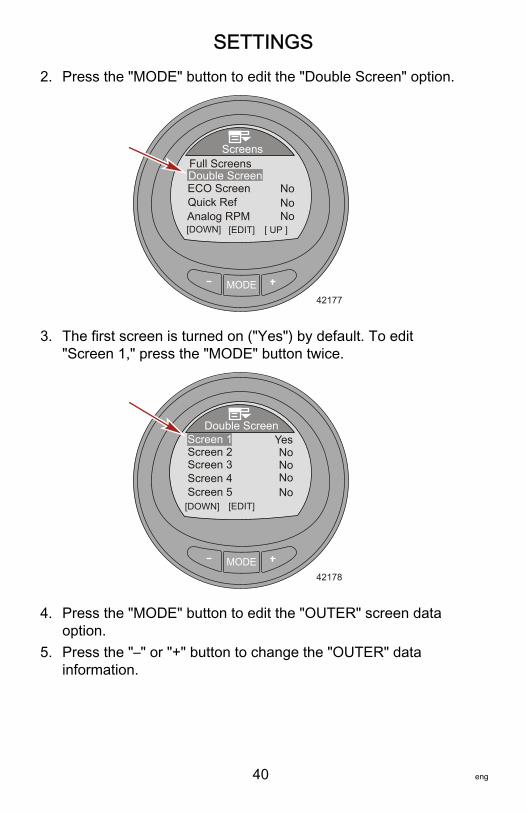
2. Press the "MODE" button to edit the "Double Screen" option.
MODE
Screens
42177
Quick RefECO Screen
[DOWN] [EDIT]
Full ScreensDouble Screen
[ UP ]Analog RPM No
NoNo
3. The first screen is turned on ("Yes") by default. To edit"Screen 1," press the "MODE" button twice.
MODE42178
[DOWN] [EDIT]
Double ScreenYesScreen 1
Screen 2Screen 3
Screen 5Screen 4
NoNo
NoNo
4. Press the "MODE" button to edit the "OUTER" screen dataoption.
5. Press the "–" or "+" button to change the "OUTER" datainformation.

SETTINGS
eng 41
NOTE: The information available for the "OUTER" and "INNER""Double Screen" is: "RPM," "Speed," "Coolant Temp," "OilTemp," "Seatemp," "Water Press," "Oil Press," "Fuel Flow,""Fuel," "Battery," and "Depth."
MODE42179
[DOWN] [SAVE]
Double ScreenRPMOUTER
INNERExit
Depth
[ UP ]
6. Press the "MODE" button to exit the "OUTER" screen dataoption.
7. Press the "–" to highlight the "INNER" screen data option.8. Press the "MODE" button to edit the "INNER" screen data
option.9. Press the "–" or "+" button to change the "INNER" data
information.
MODE42180
[DOWN] [SAVE]
Double ScreenRPMOUTER
INNERExit
Depth
[ UP ]

SETTINGS
42 eng
10.Press the "MODE" button to exit the "INNER" screen dataoption.
11.Press the "–" to highlight the "Exit" option.12.Press the "MODE" button to exit the "Screen 1" option.13.Press the "–" to highlight the "Screen 2" menu.14.Press the "MODE" button to turn "Screen 2" on ("Yes") and
to edit the available data. Complete the process asexplained in steps 4 through 11 for additional "DoubleScreen" options.
15.When finished with the "Double Screen" options, press the"–" button to highlight the "Exit" option. Press the "MODE"button to exit the "Double Screen" menu.
ADDITIONAL SCREENS OPTIONS1. While in the "Screens" menu, press the "–" button to
highlight the "ECO Screen" option.2. Press the "MODE" button to turn the option on ("Yes") or off
("No").
MODE
Screens
30476
Tri Data
ECO Screen
[DOWN] [EDIT]
Full Screens
Double Screen
[ UP ]Sys Check No
Yes
3. Press the "–" button to highlight the "Sys Check" option.

SETTINGS
eng 43
4. Press the "MODE" button to turn the option on ("Yes") or off("No").
MODE
Screens
30479
Tri Data
ECO Screen
[DOWN] [EDIT]
Full Screens
Double Screen
[ UP ]Sys Check
YesYes
5. Press the "–" button to highlight the "Analog RPM" option.6. Press the "MODE" button to turn the option on ("Yes") or off
("No").
MODE
Screens
30481
Trim/RPM
[DOWN] [EDIT]
Analog RPMAnalog Speed
[ UP ]Water Info
Yes80 Dial
Peak SpeedNoNoNoNo
7. Press the "–" button to highlight the "Analog Speed" option.8. Press the "MODE" button to turn the option on ("Yes") and
to select the maximum speed of the analog gauge.

SETTINGS
44 eng
NOTE: Pressing the "MODE" button will page through the 0–80("80 Dial"), 0–120 ("120 Dial"), and off ("No").
9. Press the "–" button to highlight the "Trim/RPM" option.10.Press the "MODE" button to turn the option on ("Yes") or off
("No").
MODE
Screens
42185
Trim/RPM
[DOWN] [EDIT]
Analog RPMAnalog Speed
[ UP ]Water Info
Yes80 Dial
Peak SpeedNoNo
Yes
11.Press the "–" button to highlight the "Peak Speed" option.

SETTINGS
eng 45
12.Press the "MODE" button to turn the option on ("Yes") or off("No").
MODE
Screens
42186
Trim/RPM
[DOWN] [EDIT]
Analog RPMAnalog Speed
[ UP ]Water Info
Yes80 Dial
Peak SpeedNo
YesYes
13.Press the "–" button to highlight the "Water Info" option.14.Press the "MODE" button to turn the option on ("Yes") or off
("No").
MODE
Screens
42188
Trim/RPM
[DOWN] [EDIT]
Analog RPMAnalog Speed
[ UP ]Water Info
Yes80 Dial
Peak SpeedYesYesYes
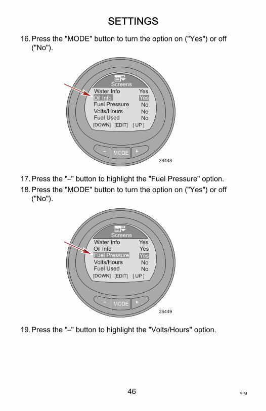
15.Press the "–" button to highlight the "Oil Info" option.
SETTINGS
46 eng
16.Press the "MODE" button to turn the option on ("Yes") or off("No").
MODE
Screens
36448
Fuel Pressure
[DOWN] [EDIT]
Water Info
[ UP ]
Oil InfoYesYes
Volts/HoursNoNo
Fuel Used No
17.Press the "–" button to highlight the "Fuel Pressure" option.18.Press the "MODE" button to turn the option on ("Yes") or off
("No").
MODE
Screens
36449
Fuel Pressure
[DOWN] [EDIT]
Water Info
[ UP ]
Oil InfoYesYes
Volts/HoursYesNo
Fuel Used No
19.Press the "–" button to highlight the "Volts/Hours" option.
SETTINGS
eng 47
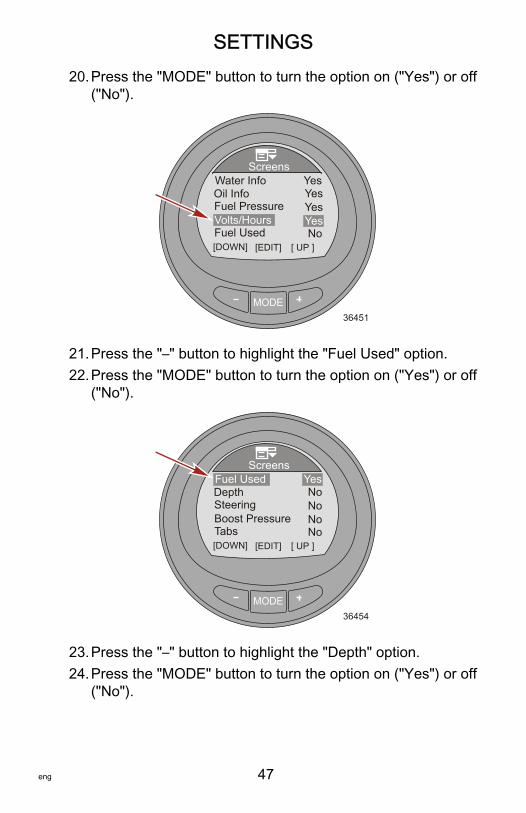
20.Press the "MODE" button to turn the option on ("Yes") or off("No").
MODE
Screens
36451
Fuel Pressure
[DOWN] [EDIT]
Water Info
[ UP ]
Oil InfoYesYes
Volts/HoursYesYes
Fuel Used No
21.Press the "–" button to highlight the "Fuel Used" option.22.Press the "MODE" button to turn the option on ("Yes") or off
("No").
MODE
Screens
36454
Steering
[DOWN] [EDIT]
Fuel Used
[ UP ]
DepthYesNo
Boost PressureTabs
NoNo
No
23.Press the "–" button to highlight the "Depth" option.24.Press the "MODE" button to turn the option on ("Yes") or off
("No").

SETTINGS
48 eng
NOTE: The "Depth" screen must be turned on to enable thedepth alarms.
MODE
Screens
36455
Steering
[DOWN] [EDIT]
Fuel Used
[ UP ]
DepthYesYes
Boost PressureTabs
NoNo
No
25.Press the "–" button to highlight the "Steering" option.26.Press the "MODE" button to turn the option on ("Yes") or off
("No").
MODE
Screens
36456
Steering
[DOWN] [EDIT]
Fuel Used
[ UP ]
DepthYesYes
Boost PressureTabs
NoYes
No
27.Press the "–" button to highlight the "Boost Pressure" option.

SETTINGS
eng 49
28.Press the "MODE" button to turn the option on ("Yes") or off("No").
MODE
Screens
36459
Steering
[DOWN] [EDIT]
Fuel Used
[ UP ]
DepthYesYes
Boost PressureTabs
YesYes
No
29.Press the "–" button to highlight the "Tabs" option.30.Press the "MODE" button to turn the option on ("Yes") or off
("No").
MODE
Screens
36463
Steering
[DOWN] [EDIT]
Fuel Used
[ UP ]
DepthYesYes
Boost PressureTabs
YesYes
Yes
31.Press the "–" button to highlight the "GPS Data" option.
SETTINGS
50 eng
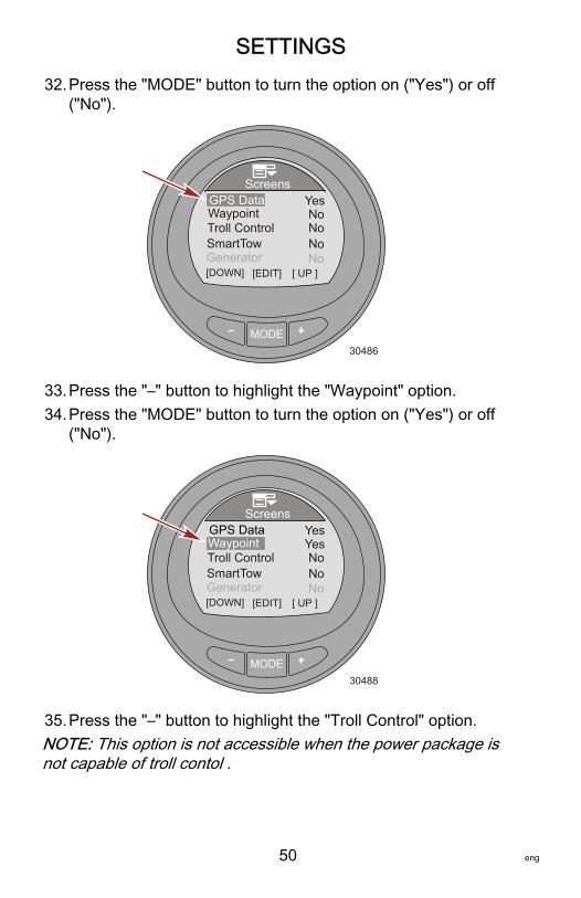
32.Press the "MODE" button to turn the option on ("Yes") or off("No").
MODE
Screens
30486
[DOWN] [EDIT]
GPS DataWaypoint
[ UP ]
SmartTow
YesNo
Troll Control
Generator No
NoNo
33.Press the "–" button to highlight the "Waypoint" option.34.Press the "MODE" button to turn the option on ("Yes") or off
("No").
MODE
Screens
30488
[DOWN] [EDIT]
GPS DataWaypoint
[ UP ]
SmartTow
Yes
Troll Control
Generator No
NoNo
Yes
35.Press the "–" button to highlight the "Troll Control" option.NOTE: This option is not accessible when the power package isnot capable of troll contol .

SETTINGS
eng 51
36.Press the "MODE" button to turn the option on ("Yes") or off("No").
MODE
Screens
30499
[DOWN] [EDIT]
GPS DataWaypoint
[ UP ]
SmartTow
Yes
Troll Control
Generator NoNo
YesYes
37.Press the "–" button to highlight the "SmartTow" option.38.Press the "MODE" button to turn the option on ("Yes") or off
("No").
MODE
Screens
30245
[DOWN] [EDIT]
GPS DataWaypoint
[ UP ]
SmartTow
Yes
Troll Control
Generator No
YesYesYes
39.Press the "–" button to highlight the "Generator" option.NOTE: The MercMonitor must be set to receive to edit thisoption. A generator capable of sending data on the J1939gateway network must be installed to monitor this option.

SETTINGS
52 eng
40.Press the "MODE" button to turn the option on ("Yes") or off("No").
MODE
Screens
30247
[DOWN] [EDIT]
GPS DataWaypoint
[ UP ]
SmartTow
Yes
Troll Control
Generator No
YesYesYes
41.Press the "–" button to highlight the "Screen Sync" option.42.Press the "MODE" button to turn the option on ("Yes") or off
("No").
MODE
Screens
32962
[DOWN] [EDIT]
Screen SyncFavorites Slide
[ UP ]
SmartTow
Yes
Exit
Generator No
2s
Yes
43.Press the "–" button to highlight the "Favorites Slide" option.

SETTINGS
eng 53
NOTE: The "Favorites Slide" seconds must be displayed for the"Favorites" screen transition to function. Select from 1–30seconds to display the selected favorites. When the secondsare set to "OFF," the "Favorites" screen must be advancedmanually using the mode button.44.Press the "MODE" button to edit the number of seconds the
favorites will display.45.Press the "+" or "–" to change the number of seconds.
MODE
Screens
33076
[DOWN] [EDIT]
Screen SyncFavorites Slide
[ UP ]
SmartTow
Yes
Exit
Generator No
2s
Yes
46.Press the "MODE" button to exit the "Favorites Slide" option.47.Press the "–" button to highlight the "Exit" option. Press the
"MODE" button to exit the "Screens" menu.
Setting the TrimEditing the trim settings menu allows you to turn the trim pop‑upon or off, change the length of time the pop‑up window remainson the screen, turn the high resolution on or off, and calibrate thegauge to the sensor. A high resolution setting will cause themonitor to display the trim position with more detailedinformation.1. While in the "Main Menu," press the "–" or "+" button to
highlight the "Settings" menu.

SETTINGS
54 eng
2. Press the "MODE" button to enter the "Settings" menu.
MODE
Main MenuPropulsion / ST
FavoritesVessel
33077
SettingsAlarms!
3. Press the "–" button to highlight the "Trim" menu.4. Press the "MODE" button to edit the "Trim" menu.
MODE
Settings
42218
Screen
TanksTrim
[DOWN] [EDIT]
Light/ContrastUnits
[ UP ]

SETTINGS
eng 55
5. Press the "MODE" button to turn the trim "Popup" windowoption on ("Yes") or off ("No").
MODE35928
Popup Time
Exit
Trim
[DOWN] [EDIT]
PopupHigh Resol.
Calibration
YesNo1 s
6. Press the "–" button to highlight the "High Resol" option.7. Press the "MODE" button to turn the high resolution option
on ("Yes") or off ("No").
MODE35929
Popup Time
Exit
Trim
[DOWN] [EDIT]
PopupHigh Resol.
Calibration
Yes
1 s
[ UP ]
Yes
8. Press the "–" button to highlight the "Popup Time" option.9. Press the "MODE" button to edit the length of time the trim
pop‑up window option remains on the screen.
SETTINGS
56 eng
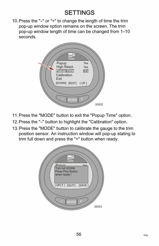
10.Press the "–" or "+" to change the length of time the trimpop‑up window option remains on the screen. The trimpop‑up window length of time can be changed from 1–10seconds.
MODE35932
Trim
[DOWN] [EDIT]
PopupHigh Resol.
Yes
5 s
[ UP ]
YesPopup Time
ExitCalibration
11.Press the "MODE" button to exit the "Popup Time" option.12.Press the "–" button to highlight the "Calibration" option.13.Press the "MODE" button to calibrate the gauge to the trim
position sensor. An instruction window will pop‑up stating totrim full down and press the "+" button when ready.
MODE35933
Trim
[ DFLT ] [QUIT]
PopupHigh Resol.
Yes
5 s
[SAVE ]
YesPopup Time
ExitCalibration
Trim full DOWNPress Plus Buttonwhen ready !
SETTINGS
eng 57
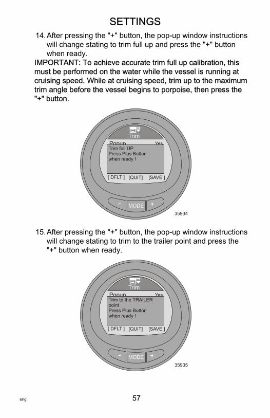
14.After pressing the "+" button, the pop‑up window instructionswill change stating to trim full up and press the "+" buttonwhen ready.
IMPORTANT: To achieve accurate trim full up calibration, thismust be performed on the water while the vessel is running atcruising speed. While at cruising speed, trim up to the maximumtrim angle before the vessel begins to porpoise, then press the"+" button.
MODE35934
Trim
[ DFLT ] [QUIT]
PopupHigh Resol.
Yes
5 s
[SAVE ]
YesPopup Time
ExitCalibration
Trim full UPPress Plus Buttonwhen ready !
15.After pressing the "+" button, the pop‑up window instructionswill change stating to trim to the trailer point and press the"+" button when ready.
MODE35935
Trim
[ DFLT ] [QUIT]
PopupHigh Resol.
Yes
5 s
[SAVE ]
YesPopup Time
ExitCalibration
Trim to the TRAILERpointPress Plus Buttonwhen ready !

SETTINGS
58 eng
16.Press the "+" button to return to the "Calibration" option.17.Press the "–" button to highlight the "Exit" option. Press the
"MODE" button to return to the "Settings" menu.18.Press the "–" button to highlight the "Exit" option. Press the
"MODE" button to return to the "Main Menu" screen.
Setting the TanksThere are two tanks available for each power package installedon the vessel. Tank number "1" can be designated as notinstalled ("Not inst") or fuel. When "Not inst" is selected, theoptions for setting the tank capacity and the calibration cannot beedited. The maximum fuel capacity is 2271 liter (600 US gal).The second tank can be designated as not installed ("Not inst"),water, fuel, or waste on 4‑Stroke engines and will automaticallydefault to oil if the gauge is installed on a vessel with a 2‑Strokeengine.Two different methods are available to calibrate the tanks: Forlinear shaped fuel tanks, choose "Default Calibration." "DefaultCalibration" assumes the tank is uniformly shaped and that eachquarter of the tank holds a quarter of its total capacity. Water andwaste tanks are typical to this linear shape tank and areautomatically set to the "Default Calibration." For irregularlyshaped fuel tanks, choose "Add Fuel Method." Fuel must beadded to the tank for each quarter of the capacity when usingthis method. The "Add Fuel Method" should be performed in thewater for an accurate representation of the tank capacity.NOTE: Tank capacity must be calibrated by either the "DefaultCalibration," or "Add Fuel Method," or the capacity will revertback to its former value.TANK 11. While in the "Main Menu," press the "–" or "+" button to
highlight the "Settings" menu.

SETTINGS
eng 59
2. Press the "MODE" button to enter the "Settings" menu.
MODE
Main MenuPropulsion / ST
FavoritesVessel
33077
SettingsAlarms!
3. Press the "–" button to highlight the "Tanks" menu.4. Press the "MODE" button to edit the "Tanks" menu.
MODE
Settings
42219
Screens
Light/Contrast
Trim
[DOWN] [EDIT]Tanks
Units
[ UP ]
5. Press the "MODE" button to edit the "Tank 1 Type" option.

SETTINGS
60 eng
6. Press the "–" or "+" button to change the tank setting.
MODE35880
[DOWN] [SAVE]
TanksTank 1 Type
[ UP ]
Tank 1 VolTank 1 CalTank 2 TypeTank 2 Vol
0.0 G
Not inst.
Fuel
7. Press the "MODE" button to exit the "Tank 1 Type" option.8. Press the "–" button to highlight the "Tank 1 Vol" capacity.9. Press the "MODE" button to edit the capacity.NOTE: The maximum capacity is 2271 liter (600 US gal).10.Press the "–" or "+" button to change the capacity of the
tank. Holding the button down will scroll through thenumbers.
MODE35881
[DOWN] [SAVE]
TanksTank 1 Type
[ UP ]
Tank 1 VolTank 1 CalTank 2 TypeTank 2 Vol
100.0 G
Not inst.
Fuel
11.Press the "MODE" button to exit the "Tank 1 Vol" option.

SETTINGS
eng 61
12.Press the "–" button to highlight the "Tank 1 Cal" option.
MODE35886
[ DFLT ] [ QUIT ]
TanksTank 1 Type
[ ADD ]
Tank 1 VolTank 1 CalTank 2 TypeTank 2 Vol
100.0 G
Not inst.
Fuel
13.Press the "MODE" button to select the type of calibration.NOTE: Two different methods are available to calibrate thetanks: For linear shaped fuel tanks, choose "DefaultCalibration." "Default Calibration" assumes the tank is uniformlyshaped and that each quarter of the tank holds a quarter of itstotal capacity. Water and waste tanks are typical to this linearshape tank. For irregularly shaped fuel tanks, choose "Add FuelMethod." Fuel must be added to the tank for each quarter of thecapacity when using this method. The "Add Fuel Method"should be performed in the water for an accurate representationof the tank capacity.NOTE: The following procedure is used for the "DefaultCalibration" method.

SETTINGS
62 eng
14.Press the "–" button to choose the "Default Calibration"method or press the "MODE" button to quit the calibration.
MODE35882
[ DFLT ] [ QUIT ]
TanksTank 1 Type
[ ADD ]
Tank 1 VolTank 1 CalTank 2 TypeTank 2 Vol
100.0 G
Not inst.
FuelDefault Calibration orAdd Fuel Method
15.Press the "MODE" button to finish "(OK)" and exit the "Tank1 Cal" option.
MODE35884
[ OK ]
TanksTank 1 TypeTank 1 VolTank 1 CalTank 2 TypeTank 2 Vol
100.0 G
Not inst.
FuelCalibration OK
NOTE: The following procedure is used for the "Add FuelMethod" of calibration.

SETTINGS
eng 63
16.Press the "+" button to choose the "Add Fuel Method" orpress the "MODE" button to quit the calibration.
MODE35887
[ DFLT ] [ QUIT ]
TanksTank 1 Type
[ ADD ]
Tank 1 VolTank 1 CalTank 2 TypeTank 2 Vol
100.0 G
Not inst.
FuelDefault Calibration orAdd Fuel Method
17.Press the "+" button to save and edit the "Add Fuel Method"of calibration.
MODE35889
TanksTank 1 Type
[ SAVE ]
Tank 1 VolTank 1 CalTank 2 TypeTank 2 Vol
100.0 G
Not inst.
FuelCalibrating Empty Tank: 0.0 GallonsPress Plus Buttonwhen ready!

SETTINGS
64 eng
18.Add 25 percent of the fuel capacity to the empty fuel tank.The gauge will list the quantity of fuel to add for eachquarter. Press the "+" button to save the calibration.
MODE36788
TanksTank 1 Type
[ SAVE ]
Tank 1 VolTank 1 CalTank 2 TypeTank 2 Vol
100.0 G
Not inst.
FuelCalibrating 1/4 Tank:25.0 GallonsPress Plus Buttonwhen ready!
19.The fuel level sensor must change a minimal value whenadding fuel. If the fuel level sensor does not change to theminimal value any time during the add fuel calibration, anerror message stating the calibration is defaulting to values("Error! Defaulting to values...") will be visible on the screen.The manual calibration process will stop when the errormessage appears. The fuel tank must be emptied and themanual calibration process must be repeated.
MODE36794
TanksTank 1 Type
[ OK ]
Tank 1 VolTank 1 CalTank 2 TypeTank 2 Vol
100.0 G
Not inst.
FuelError ! Defaulting tovalues....

SETTINGS
eng 65
20.Add 25 percent more fuel capacity to the fuel tank. Press the"+" button to save the calibration.
MODE36790
TanksTank 1 Type
[ SAVE ]
Tank 1 VolTank 1 CalTank 2 TypeTank 2 Vol
100.0 G
Not inst.
FuelFill to 1/2: 50 Gallons
Press Plus Buttonwhen ready!
21.Add 25 percent more fuel capacity to the fuel tank. Press the"+" button to save the calibration.
MODE36791
TanksTank 1 Type
[ SAVE ]
Tank 1 VolTank 1 CalTank 2 TypeTank 2 Vol
100.0 G
Not inst.
FuelFill to 3/4: 75 Gallons
Press Plus Buttonwhen ready!

SETTINGS
66 eng
22.Add 25 percent more fuel capacity to fill the fuel tank. Pressthe "+" button to save the calibration.
MODE36792
TanksTank 1 Type
[ SAVE ]
Tank 1 VolTank 1 CalTank 2 TypeTank 2 Vol
100.0 G
Not inst.
FuelFill until full: 100.0GallonsPress Plus Buttonwhen ready!
23.The screen on the monitor will state the fuel tankcalibrations is successful ("Calibrations OK").
MODE36793
TanksTank 1 Type
[ OK ]
Tank 1 VolTank 1 CalTank 2 TypeTank 2 Vol
100.0 G
Not inst.
FuelCalibrations OK
24.Press the "MODE" button to exit the calibration process.25.Press the "–" button to edit the "Tank 2 Type" option.

SETTINGS
eng 67
TANK 2The second tank can be designated as not installed ("Not inst"),water, fuel, or waste when installed on a vessel with a 4‑Strokeengine. The maximum fuel capacity is 2271 liter (600 US gal).When the tank is designated as water or waste, the calibration isautomatically selected as default and will estimate the levelbased on a linear shape capacity and the calibration cannot beedited. When fuel is selected for tank 2, the calibration methodsare the same as tank 1. Choose between the "DefaultCalibration" method or "Add Fuel Method."When the gauge is installed on a vessel with a 2‑Stroke engine,the second tank will default to oil automatically and cannot becalibrated.
Setting the AlarmsAlarm settings can be customized to the vessel specificationsand to the preference of the owner. Low fuel and critical fuellevels cannot be disabled, but can be adjusted to the preferenceof the owner. These levels can be adjusted down to 10 percentof the fuel tank volume. The shallow water depth, deep waterdepth, and waypoint distance alarms can be turned off or on.The shallow water depth alarm can be adjusted to 0.1 m (0.3 ft)and the deep water depth alarm can be adjusted to 300 m(984 ft). The pop‑up alarm warning for these settings can beturned off or on. Vessels equipped with a generator that is J1939compatible can have these alarms turned off or on.1. While in the "Main Menu," press the "–" or "+" button to
highlight the "Settings" menu.

SETTINGS
68 eng
2. Press the "MODE" button to enter the "Settings" menu.
MODE
Main MenuPropulsion / ST
FavoritesVessel
33077
SettingsAlarms!
3. Press the "–" button to highlight the "Alarms" menu.4. Press the "MODE" button to edit the "Alarms" menu.
MODE
Settings
42220
Offsets
SmartTow [DOWN] [EDIT]
AlarmsExt. Sensors
[ UP ]
Clock
5. Press the "MODE" button to enter the "Fuel Critical" option.

SETTINGS
eng 69
6. Press the "–" or "+" to edit the "Fuel Critical" percentage.This percentage cannot be set lower than 10, or more thanthe "Fuel Low" alarm setting.
MODE35859
Fuel Low
Depth DeepDepth Shallow
[DOWN] [EDIT]
AlarmsFuel Critical
[ UP ]
Waypoint Dist
10 %25 %OFFOFFOFF
7. Press the "MODE" button to exit the "Fuel Critical" option.8. Press the "–" button to highlight the "Fuel Low" option.9. Press the "MODE" button to enter the "Fuel Low" option.10.Press the "–" or "+" to edit the "Fuel Low" percentage. This
percentage cannot be set lower than 10, or more than 50percent.
MODE35860
[DOWN] [EDIT]
AlarmsFuel Critical
[ UP ]
10 %25 %OFFOFFOFF
Fuel Low
Depth DeepDepth Shallow
Waypoint Dist
11.Press the "MODE" button to exit the "Fuel Low" option.12.Press the "–" button to highlight the "Depth Shallow" option.

SETTINGS
70 eng
13.Press the "MODE" button to enter the "Depth Shallow"option.
14.Press the "–" or "+" to edit the "Depth Shallow" option. Theminimum setting is 0.1 m (0.3 ft) and the maximum setting is100 m (328 ft).
MODE35862
[DOWN] [EDIT]
AlarmsFuel Critical
[ UP ]
10 %25 %0.3 ft
OFF
Fuel Low
Depth DeepDepth Shallow
Waypoint DistOFF
15.Press the "MODE" button to exit the "Depth Shallow" option.16.Press the "–" button to highlight the "Depth Deep" option.17.Press the "MODE" button to enter the "Depth Deep" option.18.Press the "–" or "+" to edit the "Depth Deep" option. The
minimum setting is 0.2 m (0.7 ft) and the maximum setting is300 m (984 ft).
SETTINGS
eng 71
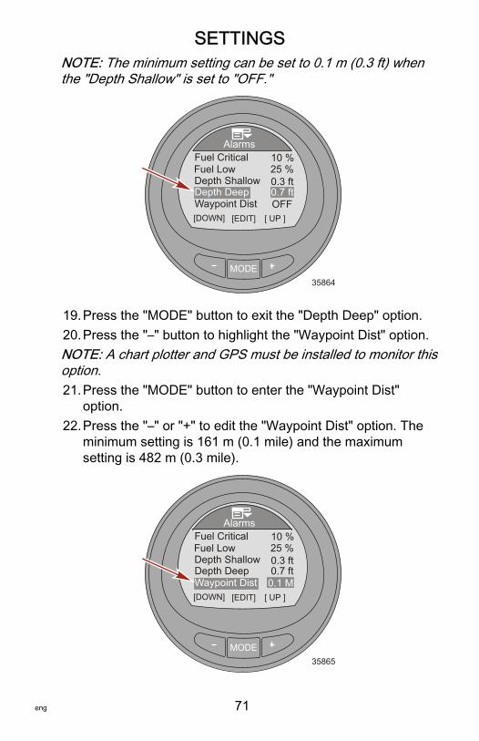
NOTE: The minimum setting can be set to 0.1 m (0.3 ft) whenthe "Depth Shallow" is set to "OFF."
MODE35864
[DOWN] [EDIT]
AlarmsFuel Critical
[ UP ]
10 %25 %0.3 ft
OFF
Fuel Low
Depth DeepDepth Shallow
Waypoint Dist0.7 ft
19.Press the "MODE" button to exit the "Depth Deep" option.20.Press the "–" button to highlight the "Waypoint Dist" option.NOTE: A chart plotter and GPS must be installed to monitor thisoption.21.Press the "MODE" button to enter the "Waypoint Dist"
option.22.Press the "–" or "+" to edit the "Waypoint Dist" option. The
minimum setting is 161 m (0.1 mile) and the maximumsetting is 482 m (0.3 mile).
MODE35865
[DOWN] [EDIT]
AlarmsFuel Critical
[ UP ]
10 %25 %0.3 ft
0.1 M
Fuel Low
Depth DeepDepth Shallow
Waypoint Dist0.7 ft
SETTINGS
72 eng
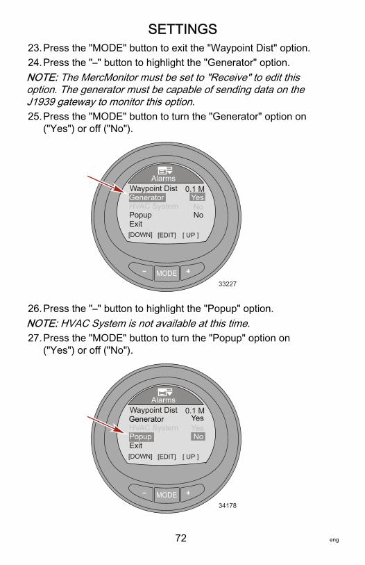
23.Press the "MODE" button to exit the "Waypoint Dist" option.24.Press the "–" button to highlight the "Generator" option.NOTE: The MercMonitor must be set to "Receive" to edit thisoption. The generator must be capable of sending data on theJ1939 gateway to monitor this option.25.Press the "MODE" button to turn the "Generator" option on
("Yes") or off ("No").
MODE33227
[DOWN] [EDIT]
Alarms
[ UP ]Exit
YesNo
0.1 MGenerator
PopupHVAC System
Waypoint Dist
No
26.Press the "–" button to highlight the "Popup" option.NOTE: HVAC System is not available at this time.27.Press the "MODE" button to turn the "Popup" option on
("Yes") or off ("No").
MODE34178
[DOWN] [EDIT]
Alarms
[ UP ]Exit
Yes
0.1 MGenerator
PopupHVAC System
Waypoint Dist
No
Yes
SETTINGS
eng 73
28.Press the "–" button to highlight the "Exit" option. Press the"MODE" button to exit the "Alarms" menu.
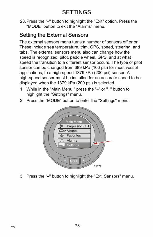
Setting the External SensorsThe external sensors menu turns a number of sensors off or on.These include sea temperature, trim, GPS, speed, steering, andtabs. The external sensors menu also can change how thespeed is recognized; pitot, paddle wheel, GPS, and at whatspeed the transition to a different sensor occurs. The type of pitotsensor can be changed from 689 kPa (100 psi) for most vesselapplications, to a high‑speed 1379 kPa (200 psi) sensor. Ahigh‑speed sensor must be installed for an accurate speed to bedisplayed when the 1379 kPa (200 psi) is selected.1. While in the "Main Menu," press the "–" or "+" button to
highlight the "Settings" menu.2. Press the "MODE" button to enter the "Settings" menu.
MODE
Main MenuPropulsion / ST
FavoritesVessel
33077
SettingsAlarms!
3. Press the "–" button to highlight the "Ext. Sensors" menu.
SETTINGS
74 eng
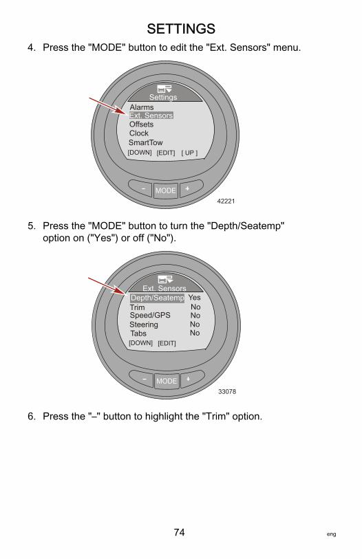
4. Press the "MODE" button to edit the "Ext. Sensors" menu.
MODE
Settings
42221
Offsets
SmartTow [DOWN] [EDIT]
AlarmsExt. Sensors
[ UP ]
Clock
5. Press the "MODE" button to turn the "Depth/Seatemp"option on ("Yes") or off ("No").
MODE33078
TabsSteeringSpeed/GPS
[DOWN] [EDIT]
Depth/SeatempExt. Sensors
YesTrim No
No
NoNo
6. Press the "–" button to highlight the "Trim" option.
SETTINGS
eng 75
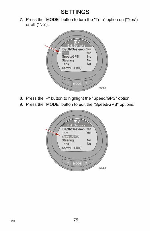
7. Press the "MODE" button to turn the "Trim" option on ("Yes")or off ("No").
MODE33080
TabsSteeringSpeed/GPS
[DOWN] [EDIT]
Depth/SeatempExt. Sensors
YesTrim
No
NoNo
Yes
8. Press the "–" button to highlight the "Speed/GPS" option.9. Press the "MODE" button to edit the "Speed/GPS" options.
MODE33081
TabsSteeringSpeed/GPS
[DOWN] [EDIT]
Depth/SeatempExt. Sensors
YesTrim
NoNo
Yes

SETTINGS
76 eng
10.Press the "MODE" button to turn the "Use Paddle" option on("Yes") or off ("No").
MODE42227
Trans Speed
Speed
[DOWN] [EDIT]
Use PaddleUse Pitot
5
NoYes
100 PSIPitot Type
GPS Enabled No[ UP ]
11.Press the "–" button to highlight the "Use Pitot" option.12.Press the "MODE" button to turn the "Use Pitot" option on
("Yes") or off ("No").
MODE42228
Trans Speed
Speed
[DOWN] [EDIT]
Use PaddleUse Pitot
5
Yes
100 PSIPitot Type
GPS Enabled No[ UP ]
Yes
13.Press the "–" button to highlight the "Pitot Type" option.

SETTINGS
eng 77
14.Press the "MODE" button to change the sensor to "100 PSI"or "200 PSI."
MODE42229
Trans Speed
Speed
[DOWN] [EDIT]
Use PaddleUse Pitot
5
Yes
100 PSIPitot Type
GPS Enabled No[ UP ]
Yes
15.Press the "–" button to highlight the "Trans Speed" option.16.Press the "MODE" button to edit the "Trans Speed" option.17.Press the "–" or "+" button to change the speed where the
paddle wheel sensor transitions to the pitot or GPS. Thetransition speed can be changed from 8 km/h (5 MPH) to56 km/h (35 MPH). Press the "MODE" button to exit the"Trans Speed" edit mode.
MODE42230
Speed
[DOWN] [EDIT]
Use PaddleUse Pitot
25
Yes
100 PSIPitot Type
GPS Enabled No[ UP ]
Yes
Trans Speed
18.Press the "–" to highlight the "GPS Enabled" option.
SETTINGS
78 eng
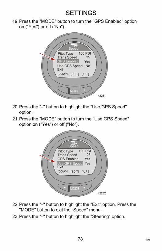
19.Press the "MODE" button to turn the "GPS Enabled" optionon ("Yes") or off ("No").
MODE42231
Speed
[DOWN] [EDIT]
Pitot Type25
100 PSI
GPS Enabled
Exit[ UP ]
YesTrans Speed
Use GPS Speed No
20.Press the "–" button to highlight the "Use GPS Speed"option.
21.Press the "MODE" button to turn the "Use GPS Speed"option on ("Yes") or off ("No").
MODE42232
Speed
[DOWN] [EDIT]
Pitot Type25
100 PSI
GPS Enabled
Exit[ UP ]
YesTrans Speed
Use GPS Speed Yes
22.Press the "–" button to highlight the "Exit" option. Press the"MODE" button to exit the "Speed" menu.
23.Press the "–" button to highlight the "Steering" option.

SETTINGS
eng 79
24.Press the "MODE" button to turn the "Steering" option on("Yes") or off ("No").
MODE33082
Tabs
Speed/GPS
[DOWN] [EDIT]
Depth/SeatempExt. Sensors
YesTrim
No
Yes
Steering Yes
25.Press the "–" button to highlight the "Tabs" option.26.Press the "MODE" button to turn the "Tabs" option on
("Yes") or off ("No").
MODE33083
Speed/GPS
[DOWN] [EDIT]
Ext. Sensors
Steering YesTabsTabs Source STBDExit
Yes
27.Press the "–" button to highlight the "Tabs Source" option.28.Press the "MODE" button to edit the "Tabs Source" option.

SETTINGS
80 eng
NOTE: The "Tabs" option must be on ("Yes") for the "TabsSource" to be activated. The "Tabs Source" will default to theengine location the gauge is set up to monitor. The enginelocation can be changed to starboard ("STBD"), port ("PORT"),starboard 2 ("STB2"), port 2 ("PRT2").
MODE33085
Speed/GPS
[DOWN] [EDIT]
Ext. Sensors
Steering YesTabsTabs Source STBDExit
Yes
[ UP ]
29.Press the "–" button to highlight the "Exit" option. Press the"MODE" button to exit the "Ext Sensors" menu.
Setting the OffsetsThe "Offsets" menu allows for compensation for inaccuratesensors, sets a transition speed from one speed sensor toanother, inverts a steering sensor, and corrects the amount offuel used. Sensors that can be modified are; sea temperature,depth, paddle wheel hertz, pitot pressure, and steering position.1. While in the "Main Menu," press the "–" or "+" button to
highlight the "Settings" menu.

SETTINGS
eng 81
2. Press the "MODE" button to enter the "Settings" menu.
MODE
Main MenuPropulsion / ST
FavoritesVessel
33077
SettingsAlarms!
3. Press the "–" button to highlight the "Offsets" menu.4. Press the "MODE" button to edit the "Offsets" menu.
MODE
Settings
42234
SmartTow [DOWN] [EDIT]
AlarmsExt. Sensors
[ UP ]
ClockOffsets
5. Press the "MODE" button to edit the "Seatemp" option.

SETTINGS
82 eng
6. Press the "–" or "+" button to change the sea temperaturecorrection from –23.3 to –12.2 °C (–10 to 10 °F).
MODE42235
[DOWN] [SAVE]
Offsets
[ UP ]
6 F0 ft4.9
1.00No
SeatempDepthPaddlePitotSteer Inv
7. Press the "MODE" button to exit the "Seatemp" option.8. Press the "–" button to highlight the "Depth" option.9. Press the "MODE" button to edit the "Depth" option. The
depth offset can be changed ± 30.5 m (100 ft).10.Press the "–" or "+" button to change the depth offset.
MODE42236
[DOWN] [SAVE]
Offsets
[ UP ]
6 F6 ft4.9
1.00No
SeatempDepthPaddlePitotSteer Inv
11.Press the "MODE" button to exit the "Depth" option.12.Press the "–" button to highlight the "Paddle" option.13.Press the "MODE" button to edit the "Paddle" option.

SETTINGS
eng 83
14.Press the "–" or "+" button to change the paddle offset. Theoffset can be changed from 3.4 Hz to 6.4 Hz.
MODE42237
[DOWN] [SAVE]
Offsets
[ UP ]
6 F6 ft4.9
1.00No
SeatempDepthPaddlePitotSteer Inv
15.Press the "MODE" button to exit the "Paddle" option.16.Press the "–" button to highlight the "Pitot" option.17.Press the "MODE" button to edit the "Pitot" option.18.Press the "–" or "+" button to change the pitot offset. The
offset can be changed from 0.50 to 1.50.
MODE42238
[DOWN] [SAVE]
Offsets
[ UP ]
6 F6 ft4.9
1.00No
SeatempDepthPaddlePitotSteer Inv
19.Press the "MODE" button to exit the "Pitot" option.20.Press the "–" button to highlight the "Steer Inv" option.
SETTINGS
84 eng
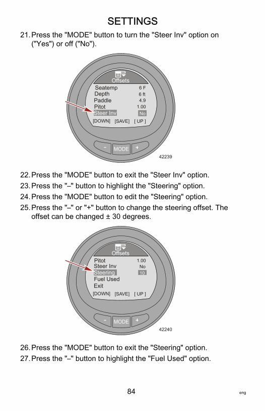
21.Press the "MODE" button to turn the "Steer Inv" option on("Yes") or off ("No").
MODE42239
[DOWN] [SAVE]
Offsets
[ UP ]
6 F6 ft4.9
1.00No
SeatempDepthPaddlePitotSteer Inv
22.Press the "MODE" button to exit the "Steer Inv" option.23.Press the "–" button to highlight the "Steering" option.24.Press the "MODE" button to edit the "Steering" option.25.Press the "–" or "+" button to change the steering offset. The
offset can be changed ± 30 degrees.
MODE42240
[DOWN] [SAVE]
Offsets
[ UP ]
10
1.00No
Fuel UsedSteering
Exit
PitotSteer Inv
26.Press the "MODE" button to exit the "Steering" option.27.Press the "–" button to highlight the "Fuel Used" option.

SETTINGS
eng 85
28.Press the "MODE" button to edit the "Fuel Used" option.
MODE42241
[DOWN] [SAVE]
Offsets
[ UP ]
10
1.00No
Fuel UsedSteering
Exit
PitotSteer Inv
29.Press the "MODE" button to edit the "Multiplier" option.30.Press the "–" or "+" button to change the multiplier offset.
The offset can be changed from 0.50 to 1.50.NOTE: The "Multiplier" is used to fine‑tune the fuel gaugesender to correct for fuel used errors. If the gauge indicates that10 gallons of fuel was used, but the actual fuel that was addedis 14 gallons, change the multiplier to 1.40. If the gaugeindicates that 10 gallons of fuel was used, but the actual fuelthat was added is only 8 gallons, change the multiplier to 0.80.
MODE35922
[DOWN] [SAVE] [ UP ]
Fuel Used
0.0 G1.0
Add FuelMultiplier
Exit
31.Press the "MODE" button to exit the "Multiplier" option.
SETTINGS
86 eng
32.Press the "–" button to highlight the "Add Fuel" option.33.Press the "–" or "+" button to change the amount of fuel that
was actually added to the fuel tank to correct for fuelcapacity errors.
NOTE: The "Add Fuel" option functions the same as themultiplier. If the gauge indicates that 10 gallons of fuel wasused, but the actual fuel that was added is 14 gallons, changethe "Add Fuel" to 14.0. If the gauge indicates that 10 gallons offuel was used, but the actual fuel that was added is only 8gallons, change the "Add Fuel" to 8.0 gallons. The gauge willcalculate the multiplier and will automatically change thenumber in the "Multiplier" option.34.Press the "–" button to highlight the "Exit" option. Press the
"MODE" button to exit the "Fuel Used" option.35.Press the "–" button to highlight the "Exit" option. Press the
"MODE" button to exit the "Offsets" menu.
Setting the ClockThe "Clock" can be set to display a 24 hour day or a 12 hour(AM, PM) day. It can also be updated automatically when using aGPS. The GPS must be turned on ("Yes") in the externalsensors ("Ext. Sensors") menu for the GPS menus to beenabled. The clock setting must have the "GPS Update" turnedon ("Yes") for the universal time coordinated (UTC) to function.The UTC can be offset from –13 hours to +13 hours.1. While in the "Main Menu," press the "–" or "+" button to
highlight the "Settings" menu.
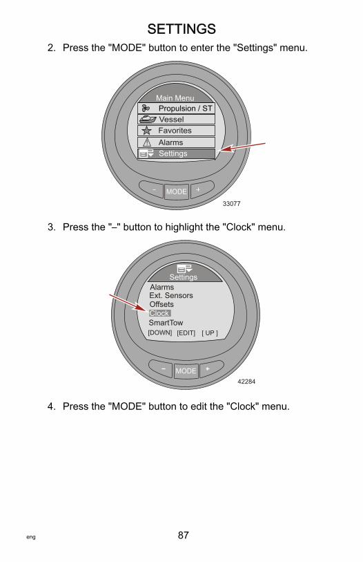
SETTINGS
eng 87
2. Press the "MODE" button to enter the "Settings" menu.
MODE
Main MenuPropulsion / ST
FavoritesVessel
33077
SettingsAlarms!
3. Press the "–" button to highlight the "Clock" menu.
MODE
Settings
42284
SmartTow [DOWN] [EDIT]
AlarmsExt. Sensors
[ UP ]
ClockOffsets
4. Press the "MODE" button to edit the "Clock" menu.

SETTINGS
88 eng
5. Press the "MODE" button to change the "Clock Format"option to 12 hour ("12h"), or 24 hour ("24h").
MODE35827
GPS UTCGPS Update
[DOWN] [EDIT]
Hour
[ UP ]
ClockClock Format 24h
Min1345No0h
6. Press the "–" button to highlight the "Hour" option.7. Press the "MODE" button to edit the "Hour" option.8. Press the "–" or "+" button to edit the hour time.
MODE35828
[DOWN] [EDIT] [ UP ]
ClockClock Format 24h
1345No0hGPS UTC
GPS Update
HourMin
9. Press the "MODE" button to exit the hour edit mode.10.Press the "–" button to highlight the "Min" option.11.Press the "MODE" button to edit the "Min" option.

SETTINGS
eng 89
12.Press the "–" or "+" button to edit the minutes time.
MODE35829
[DOWN] [EDIT] [ UP ]
ClockClock Format 24h
1345No0hGPS UTC
GPS Update
HourMin
13.Press the "MODE" button to exit the minutes edit mode.NOTE: A GPS must be connected to the monitor for the "GPSUpdate" to function, set waypoints, display GPS speed, UTCtime, latitude, and longitude. A SmartCraft GPS puck must beinstalled to use the GPS speed based cruise control. If a GPS isnot available, press the "–" button to highlight the "Exit" option.Press the "MODE" button to exit the clock menu.14.Press the "–" button to highlight the "GPS Update" option.15.Press the "MODE" button to change the "GPS Update"
option to on ("Yes") or off ("No").
MODE35830
[DOWN] [EDIT] [ UP ]
ClockClock Format 24h
1345Yes0hGPS UTC
GPS Update
HourMin

SETTINGS
90 eng
16.Press the "–" button to highlight the "GPS UTC" option.17.Press the "MODE" button to edit the "GPS UTC" option.18.Press the "–" or "+" button to edit the UTC offset time
according to your vessel's location. The UTC can be offsetfrom –13 hours to +13 hours.
MODE35836
[DOWN] [EDIT] [ UP ]
Clock1345
Yes0hGPS UTC
GPS Update
HourMin
Exit
19.Press the "MODE" button to exit the "GPS UTC" option.20.Press the "–" to highlight the "Exit" option and press the
"MODE" button to exit the "Clock" menu.
Smart Tow SettingsThe "SmartTow" setting allows the user to select the type ofspeed sensor to use when Smart Tow is in use. "SmartTow"settings also allows the user to select the type of speed filter touse. Choose to turn the filter off, low, medium, or high. Choosing"OFF" has the most sensitivity and will maintain the vessel speedwith less fluctuation in the actual speed. Use the filters if thepaddle wheel speed is unstable causing unwanted engine RPMfluctuation. The "LOW" filter setting is the most responsive andwill allow more actual speed fluctuation than when the filter isturned "OFF." The "HIGH" filter setting is the least responsiveand will allow the most speed fluctuation and will slow the rate atwhich the speed changes.1. While in the "Main Menu," press the "–" or "+" button to
highlight the "Settings" menu.

SETTINGS
eng 91
2. Press the "MODE" button to enter the "Settings" menu.
MODE
Main MenuPropulsion / ST
FavoritesVessel
33077
SettingsAlarms!
3. Press the "–" button to highlight the "SmartTow" menu.4. Press the "MODE" button to enter the "SmartTow" menu.
MODE
Settings
42286
SmartTow [DOWN] [EDIT]
AlarmsExt. Sensors
[ UP ]
ClockOffsets

SETTINGS
92 eng
5. Press the "MODE" button to change the Smart Tow "SpeedInput" option to paddle wheel ("Paddle") or to global positionsatellite "GPS."
MODE
SmartTow
35849
OFF
[DOWN] [EDIT]
Speed InputSpeed FilterExit
Paddle
6. Press the "–" button to highlight the "Speed Filter" option.7. Press the "MODE" button to change the filter to "OFF,"
"LOW," "MEDIUM," or "HIGH."
MODE
SmartTow
35854
OFF
[DOWN] [EDIT]
Speed InputSpeed FilterExit
Paddle
[ UP ]
8. Press the "–" button to highlight the "Exit" option and press"MODE" to exit the "SmartTow" menu.
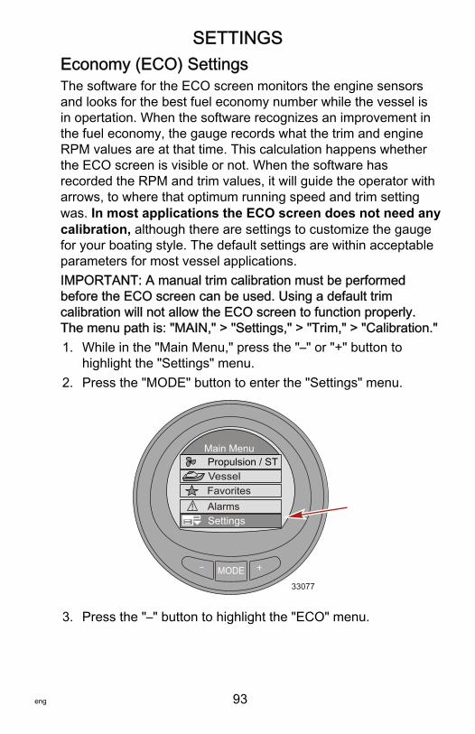
SETTINGS
eng 93
Economy (ECO) SettingsThe software for the ECO screen monitors the engine sensorsand looks for the best fuel economy number while the vessel isin opertation. When the software recognizes an improvement inthe fuel economy, the gauge records what the trim and engineRPM values are at that time. This calculation happens whetherthe ECO screen is visible or not. When the software hasrecorded the RPM and trim values, it will guide the operator witharrows, to where that optimum running speed and trim settingwas. In most applications the ECO screen does not need anycalibration, although there are settings to customize the gaugefor your boating style. The default settings are within acceptableparameters for most vessel applications.IMPORTANT: A manual trim calibration must be performedbefore the ECO screen can be used. Using a default trimcalibration will not allow the ECO screen to function properly.The menu path is: "MAIN," > "Settings," > "Trim," > "Calibration."1. While in the "Main Menu," press the "–" or "+" button to
highlight the "Settings" menu.2. Press the "MODE" button to enter the "Settings" menu.
MODE
Main MenuPropulsion / ST
FavoritesVessel
33077
SettingsAlarms!
3. Press the "–" button to highlight the "ECO" menu.

SETTINGS
94 eng
NOTE: The default settings are within acceptable parametersfor most vessel applications.
MODE
Settings
42288
Exit [DOWN] [EDIT]
ECOSystem
[ UP ]
HelpGateway
4. Press the "MODE" button to edit the "ECO" menu.5. Press the "MODE" button to edit the "Min. RPM" option.
• "Min. RPM" – Is used to customize the gauge for yourboating style. This is the lowest RPM value the engineneeds to achieve for the gauge to begin monitoring forthe best fuel economy. The default setting is 2300 RPM.
6. Press the "–" or "+" button to change the minimum RPM.
MODE
ECO
42291
Trim Accuracy[%] [DOWN] [EDIT]
Min. RPMMax. RPM
MPG timeRPM time
23004300
0.74
0.7
7. Press the "MODE" button to exit the "Min. RPM" edit option.8. Press the "–" button to highlight the "Max. RPM" option.
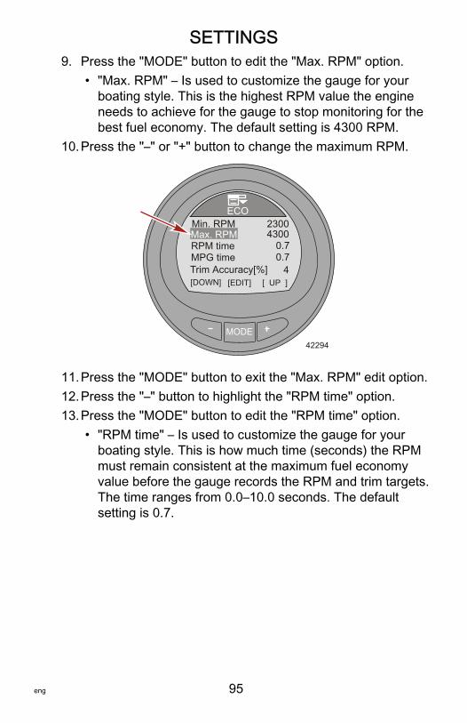
SETTINGS
eng 95
9. Press the "MODE" button to edit the "Max. RPM" option.• "Max. RPM" – Is used to customize the gauge for your
boating style. This is the highest RPM value the engineneeds to achieve for the gauge to stop monitoring for thebest fuel economy. The default setting is 4300 RPM.
10.Press the "–" or "+" button to change the maximum RPM.
MODE
ECO
42294
Trim Accuracy[%] [DOWN] [EDIT]
Min. RPMMax. RPM
MPG timeRPM time
23004300
0.74
0.7
[ UP ]
11.Press the "MODE" button to exit the "Max. RPM" edit option.12.Press the "–" button to highlight the "RPM time" option.13.Press the "MODE" button to edit the "RPM time" option.
• "RPM time" – Is used to customize the gauge for yourboating style. This is how much time (seconds) the RPMmust remain consistent at the maximum fuel economyvalue before the gauge records the RPM and trim targets.The time ranges from 0.0–10.0 seconds. The defaultsetting is 0.7.

SETTINGS
96 eng
14.Press the "–" or "+" button to change the "RPM time."
MODE
ECO
42295
Trim Accuracy[%] [DOWN] [EDIT]
Min. RPMMax. RPM
MPG timeRPM time
23004300
0.74
0.7
[ UP ]
15.Press the "MODE" button to exit the "RPM time" edit option.16.Press the "–" button to highlight the "MPG time" option.17.Press the "MODE" button to edit the "MPG time" option.
• "MPG time" – Is used to customize the gauge for yourboating style. This is how much time (seconds) the bestfuel economy must remain consistent at the maximumvalue before the gauge records the RPM and trim targets.The time ranges from 0.0–10.0 seconds. The defaultsetting is 0.7.
18.Press the "–" or "+" button to change the "MPG time."
MODE
ECO
42296
Trim Accuracy[%] [DOWN] [EDIT]
Min. RPMMax. RPM
MPG timeRPM time
23004300
0.74
0.7
[ UP ]
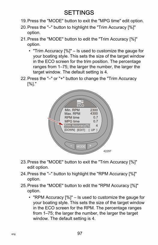
SETTINGS
eng 97
19.Press the "MODE" button to exit the "MPG time" edit option.20.Press the "–" button to highlight the "Trim Accuracy [%]"
option.21.Press the "MODE" button to edit the "Trim Accuracy [%]"
option.• "Trim Accuracy [%]" – Is used to customize the gauge for
your boating style. This sets the size of the target windowin the ECO screen for the trim position. The percentageranges from 1–75; the larger the number, the larger thetarget window. The default setting is 4.
22.Press the "–" or "+" button to change the "Trim Accuracy[%]."
MODE
ECO
42297
Trim Accuracy[%] [DOWN] [EDIT]
Min. RPMMax. RPM
MPG timeRPM time
23004300
0.74
0.7
[ UP ]
23.Press the "MODE" button to exit the "Trim Accuracy [%]"edit option.
24.Press the "–" button to highlight the "RPM Accuracy [%]"option.
25.Press the "MODE" button to edit the "RPM Accuracy [%]"option.• "RPM Accuracy [%]" – Is used to customize the gauge for
your boating style. This sets the size of the target windowin the ECO screen for the RPM. The percentage rangesfrom 1–75; the larger the number, the larger the targetwindow. The default setting is 4.

SETTINGS
98 eng
26.Press the "–" or "+" button to change the "RPM Accuracy[%]."
MODE
ECO
42298
Trim Accuracy[%]
[DOWN] [EDIT]
MPG timeRPM time
0.74
0.7
[ UP ]
RPM Accuracy[%] Exit
4
27.Press the "MODE" button to exit the "RPM Accuracy [%]"edit option.
28.Press the "–" button to highlight the "Exit" option. Press the"MODE" button to exit the "ECO" menu.
Setting the SystemThe "System" menu displays information about the engine, itslocation, the location of the station, the software version and thelevel of the gauge. This information cannot be edited.The gauge can also be reset to the factory default settings.Resetting to factory default will erase all customized menuoptions. Additionally, the name of the gauge can be edited withup to 14 characters. When the gauge is not connected to anengine, the gauge can be set to "Simulator." This can be usedfor a visualization simulation of how the gauge screens willappear when installed in a vessel.1. While in the "Main Menu," press the "–" or "+" button to
highlight the "Settings" menu.

SETTINGS
eng 99
2. Press the "MODE" button to enter the "Settings" menu.
MODE
Main MenuPropulsion / ST
FavoritesVessel
33077
SettingsAlarms!
3. Press the "–" button to highlight the "System" menu.4. Press the "MODE" button to edit the "System" menu.
MODE
Settings
42302
Exit [DOWN] [EDIT]
ECOSystem
[ UP ]
HelpGateway
5. Press the "–" button to highlight "Name."6. Press the "MODE" button to access the "Name" option. The
name window will open up on the right side of the gauge.NOTE: The default name is Mercury.7. Press the "–" or "+" to choose the first letter of the gauge
name. To save the letter and move to the next letterselection, press the "MODE" button.

SETTINGS
100 eng
NOTE: The gauge name can contain up to 14 characters. Thereis one empty character and 26 letter characters available. All 14characters must be selected before exiting the "Name" option.
MODE
System
33086
V2.04 Lvl 3
Location
[DOWN] [EDIT]
Engine
NameSTBD ST 1
STERNDRIVE
PortSoftwareSimulator No
[ UP ]
8. After the last character is saved, the name window is notactive and the program returns to the "Name" option.
9. Press the "–" to highlight the "Simulator" option and press"MODE" to activate the simulation.
NOTE: The "Simulator" option is available when the monitor ispowered with a 12 volt source for display purpose only. Thisscreen cannot be activated when connected to a powerpackage.10.Press the "–" to highlight the "Reset All" option.IMPORTANT: Resetting to factory default will erase allcustomized menu options. Refer to "Reset Gauge to the FactoryDefault Settings."

SETTINGS
eng 101
11.Press the "–" to highlight the "Exit" option and press "MODE"to return to the "Settings" menu.
MODE
System
33087
V2.04 Lvl 3
Reset All
[EDIT]
Name PortSoftwareSimulator No
[ UP ]Exit
Reset Gauge to the Factory Default SettingsIMPORTANT: Performing a reset will return the gauge to thefactory defaults, eliminating any installation and calibrationsperformed during the set up of the product.1. While in the "Main Menu," press the "–" or "+" button to
highlight the "Settings" menu.2. Press the "MODE" button to enter the "Settings" menu.
MODE
Main MenuPropulsion / ST
FavoritesVessel
33077
SettingsAlarms!
3. Press the "–" button to highlight the "System" menu.
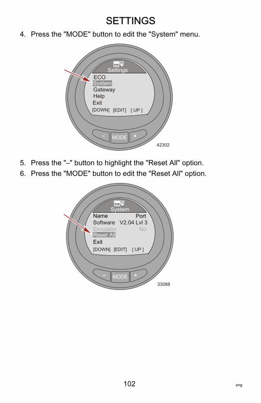
SETTINGS
102 eng
4. Press the "MODE" button to edit the "System" menu.
MODE
Settings
42302
Exit [DOWN] [EDIT]
ECOSystem
[ UP ]
HelpGateway
5. Press the "–" button to highlight the "Reset All" option.6. Press the "MODE" button to edit the "Reset All" option.
MODE
System
33088
V2.04 Lvl 3
[EDIT]
Name PortSoftwareSimulator No
[ UP ]ExitReset All
[DOWN]

SETTINGS
eng 103
7. Press the "+" to reset the gauge to the factory defaultsettings or press the "MODE" button to quit the resetfunction.
MODE
Settings
42310
[QUIT]
NameNo
AAAA
ExitReset AllSimulator
[ UP ]
RESET all your Settings to Factory Defaults?
Gateway SettingsGateway is a software interface that allows or controls access toother programs through a NMEA 2000 or J1939 protocol; achannel for communication to share information. The software iscapable of transmitting (TX) information to, and receiving (RX)information from various parameter group number (PGN)products.1. While in the "Main Menu," press the "–" or "+" button to
highlight the "Settings" menu.

SETTINGS
104 eng
2. Press the "MODE" button to enter the "Settings" menu.
MODE
Main MenuPropulsion / ST
FavoritesVessel
33077
SettingsAlarms!
3. Press the "–" button to highlight the "Gateway" menu.4. Press the "MODE" button to edit the "Gateway" menu.
MODE
Settings
42315
Exit [DOWN] [EDIT]
ECOSystem
[ UP ]
HelpGateway

SETTINGS
eng 105
5. Press the "MODE" button to edit the "Gateway" option to"NMEA 2000," "J1939," or "OFF."
MODE33089
Tab Data [DOWN] [EDIT]
Engine# of Engines
GatewayGatewayGateway
NMEA 2000Receive
SingleSTBD
Receive
6. Press the "–" button to highlight the next "Gateway" menu.7. Press the "MODE" button to edit the "Gateway" option to
"Transmit" (TX) or "Receive" (RX).NOTE: Only choose "Receive" when the monitor is used with anengine that is not SmartCraft compatible. The engine must beJ1939 or NMEA 2000 compatible.
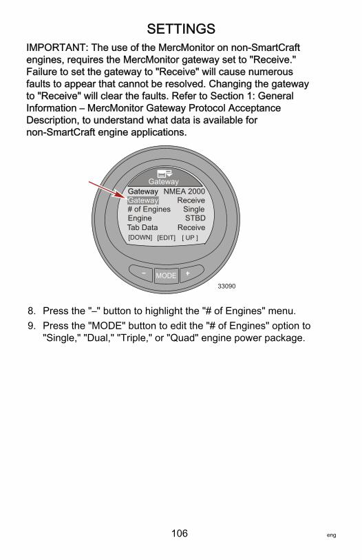
SETTINGS
106 eng
IMPORTANT: The use of the MercMonitor on non‑SmartCraftengines, requires the MercMonitor gateway set to "Receive."Failure to set the gateway to "Receive" will cause numerousfaults to appear that cannot be resolved. Changing the gatewayto "Receive" will clear the faults. Refer to Section 1: GeneralInformation – MercMonitor Gateway Protocol AcceptanceDescription, to understand what data is available fornon‑SmartCraft engine applications.
MODE33090
Tab Data [DOWN] [EDIT]
Engine# of Engines
GatewayGatewayGateway
NMEA 2000Receive
SingleSTBD
Receive[ UP ]
8. Press the "–" button to highlight the "# of Engines" menu.9. Press the "MODE" button to edit the "# of Engines" option to
"Single," "Dual," "Triple," or "Quad" engine power package.

SETTINGS
eng 107
NOTE: Only level 3 can edit the "# of Engines" option. All otherMercMonitor models will default to "Single."
MODE33097
Tab Data [DOWN] [EDIT]
Engine# of Engines
GatewayGatewayGateway
NMEA 2000Receive
SingleSTBD
Receive[ UP ]
10.Press the "–" button to highlight the "Engine" menu.11.Press the "MODE" button to edit the "Engine" option to
starboard ("STBD"), port ("PORT"), starboard 2 ("STB2"), orport 2 ("PRT2").
IMPORTANT: This menu option assigns the gauge to a specificengine.
MODE33096
Tab Data [DOWN] [EDIT]
Engine# of Engines
GatewayGatewayGateway
NMEA 2000Receive
SingleSTBD
Receive[ UP ]
12.Press the "–" button to highlight the "Tab Data" menu.

SETTINGS
108 eng
13.Press the "MODE" button to edit the "Tab Data" option to"Transmit" (TX) or "Receive" (RX).
MODE33224
Tab Data [DOWN] [EDIT]
Engine# of Engines
GatewayGatewayGateway
NMEA 2000Receive
SingleSTBD
Receive[ UP ]
14.Press the "–" button to highlight the "Exit" option. Press the"MODE" button to return to the "Settings" menu.
Help Menu1. While in the "Main Menu," press the "–" or "+" button to
highlight the "Settings" menu.2. Press the "MODE" button to enter the "Settings" menu.
MODE
Main MenuPropulsion / ST
FavoritesVessel
33077
SettingsAlarms!
3. Press the "–" button to highlight the "Help" menu.
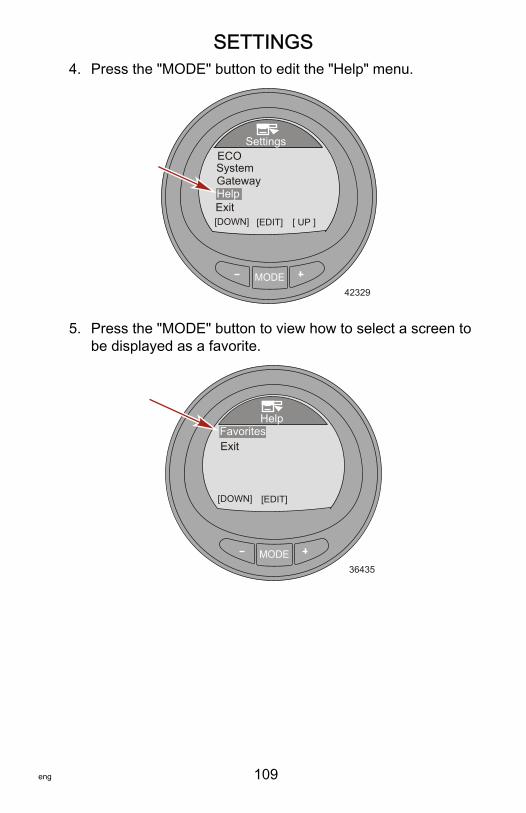
SETTINGS
eng 109
4. Press the "MODE" button to edit the "Help" menu.
MODE
Settings
42329
Exit [DOWN] [EDIT]
ECOSystem
[ UP ]
HelpGateway
5. Press the "MODE" button to view how to select a screen tobe displayed as a favorite.
MODE
Help
36435
[DOWN] [EDIT]
ExitFavorites
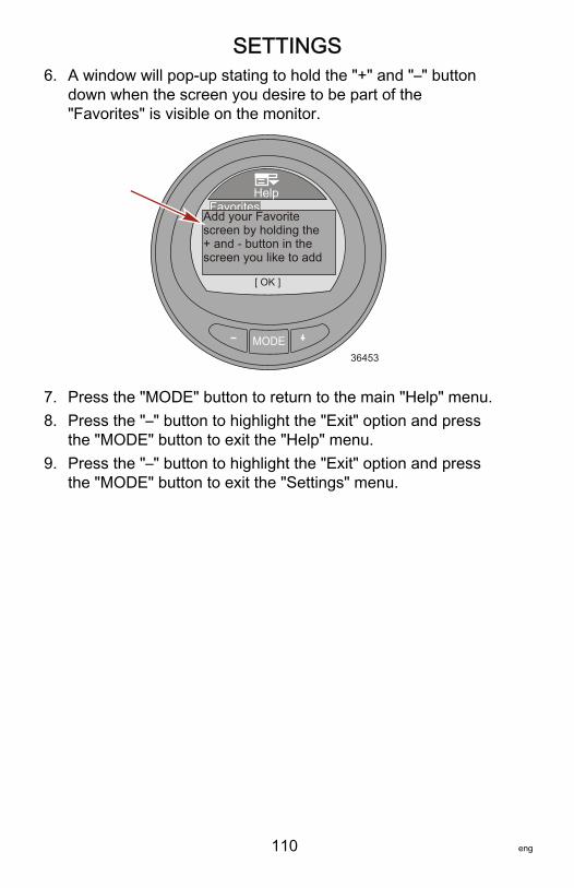
SETTINGS
110 eng
6. A window will pop‑up stating to hold the "+" and "–" buttondown when the screen you desire to be part of the"Favorites" is visible on the monitor.
MODE
Help
36453
[ OK ]
ExitFavorites
Add your Favoritescreen by holding the + and - button in thescreen you like to add
7. Press the "MODE" button to return to the main "Help" menu.8. Press the "–" button to highlight the "Exit" option and press
the "MODE" button to exit the "Help" menu.9. Press the "–" button to highlight the "Exit" option and press
the "MODE" button to exit the "Settings" menu.

PROPULSION MENU
eng 111
Using Propulsion ScreensThe "Propulsion" menu screens will display information about theboat propulsion systems. Screens that are available in the"Propulsion" menu may vary according to the engine type, butmay include the following:• Battery voltage• RPM• Water pressure• Coolant temperature• Oil temperature• Oil pressure• Peak speed• Boost pressure• Peak RPM• Trim position• Tab position• Troll control• Smart Tow
Available Propulsion Screens
Troll Control
Displays an icon to indicate thetroll control is turned on or off. Itcan be controlled with thevessel speed through the activesensor or with the engine RPM.
Troll Control
[DOWN]36114
ON
[MODE] [ UP ]MUST BE IN IDLE
SETMPH
MPHPDL 4.5
4.8OFF

PROPULSION MENU
112 eng
Water
Displays the engine RPM,vessel speed through the activesensor, coolant temperature,and water pressure.
RPMSpeed
Coolant TempWater Press
RPM
MPHPDL
oC
Bar
205012.71958.36
Water
36081[ EXIT ] [ NEXT ]
Oil
Displays the engine RPM,vessel speed through the activesensor, oil temperature, and oilpressure.
RPMSpeed
Oil TempOil Press
RPM
MPHPDL
oC
Bar
205012.72052.84
Oil
36085[ EXIT ] [ NEXT ]
Peak Speed
Displays the engine RPM,vessel speed through the activesensor, the peak vessel speed,and what the engine RPM wasat that peak vessel speed. Thepeak values can be reset.
RPMSpeed
Peak SpeedRPM @ Speed
RPM
MPHPDL
RPM
205012.7
585800
MPH
[OPTION]
Peak Speed
36087[ EXIT ] [ NEXT ]
Fuel PressureDisplays the engine RPM, fuelpressure, and amount of fuelthat is currently used per hour.
Fuel Pressure
[ EXIT ] [ NEXT ]
RPMFuel PressFuel Flow
RPM
BAR
205012.7
8 L/H
36095
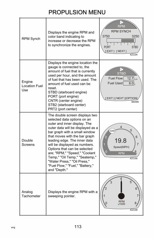
PROPULSION MENU
eng 113
RPM Synch
Displays the engine RPM andcolor band indicating toincrease or decrease the RPMto synchronize the engines.
[ EXIT ] [ NEXT ]
RPM SYNCH
PORT
3750
42334
RPM
3250
STBD
EngineLocation FuelUse
Displays the engine location thegauge is connected to, theamount of fuel that is currentlyused per hour, and the amountof fuel that has been used. Theamount of fuel used can bereset.STBD (starboard engine)PORT (port engine)CNTR (center engine)STB2 (starboard center)PRT2 (port center)
STBD
[ EXIT ] [ NEXT ]
Fuel FlowFuel Used
L/H12.78.0 L
[OPTION]36099
DoubleScreens
The double screen displays twoselected data options on anouter and inner display. Theouter data will be displayed as abar graph with a small windowthat moves with the bar graphleading edge. The inner datawill be displayed as numbers.Options that can be selectedare; "RPM," "Speed," "CoolantTemp," "Oil Temp," "Seatemp,""Water Press," "Oil Press,""Fuel Flow," "Fuel," "Battery,"and "Depth."
42336
0
1
2
34
5
6
7
8
3280
RPM
Speed(MPH)
19.8
AnalogTachometer
Displays the engine RPM with asweeping pointer.
42338
0
1
2
34
5
6
7
8RPMX1000
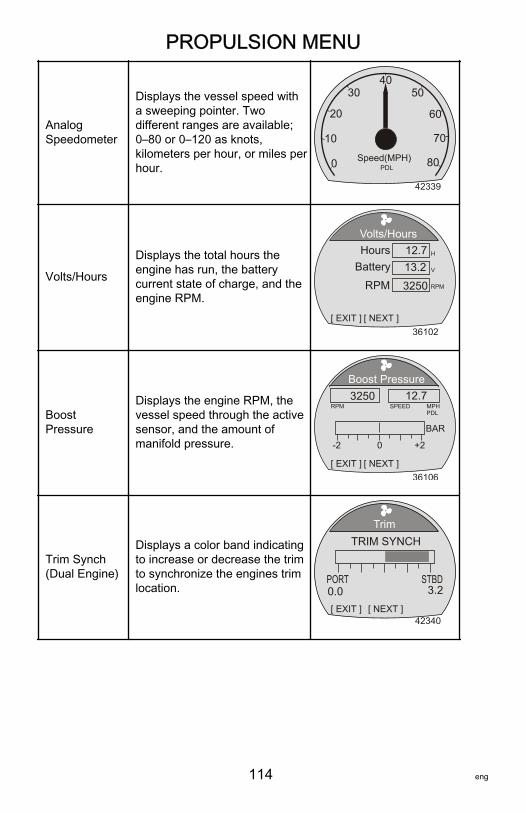
PROPULSION MENU
114 eng
AnalogSpeedometer
Displays the vessel speed witha sweeping pointer. Twodifferent ranges are available;0–80 or 0–120 as knots,kilometers per hour, or miles perhour.
42339
0
10
20
3040
50
60
70
80Speed(MPH)PDL
Volts/Hours
Displays the total hours theengine has run, the batterycurrent state of charge, and theengine RPM.
Volts/Hours
[ EXIT ] [ NEXT ]
HoursBattery
H12.713.2 V
RPM RPM3250
36102
BoostPressure
Displays the engine RPM, thevessel speed through the activesensor, and the amount ofmanifold pressure.
Boost Pressure
[ EXIT ] [ NEXT ]
SPEED12.7
MPHPDL
RPM3250
36106
-2 +20
BAR
Trim Synch(Dual Engine)
Displays a color band indicatingto increase or decrease the trimto synchronize the engines trimlocation.
[ EXIT ] [ NEXT ]
TRIM SYNCH
PORT0.0
42340
Trim
3.2STBD

PROPULSION MENU
eng 115
Trim
Displays the position of the trimwith a moving propeller icon anddisplays the trim positionnumber relative to the propellericon.
Trim
[ EXIT ] [ NEXT ]36109
10
0
25
9.5
Trim/Tab
Displays the position of the portand starboard tabs with amoving tab icon and the trimposition with a moving propellericon. A number relative to theposition of the icons is alsodisplayed in the lower portion ofthe screen.
Trim/Tab
[ EXIT ] [ NEXT ]36527
10
0
25
25
STBDPORT
0.0 0.0
Smart Tow
Displays an icon to indicateSmart Tow is turned on or off,selects cruise control or launchcontrol, selects the launchcontrol level one through fiveincluding ECO, allows thecreation of up to eightcustomized launch levelsbeyond launch level ECO,selects if Smart Tow is basedon RPM or speed.
SmartTow
36125[DOWN] [MODE] [ UP ]
ON + / - TO ENGAGE SETRPM
ACTRPM 1000
850OFF
PROFILE : Cruise
RPM

PROPULSION MENU
116 eng
Troll Control ScreenThe "Troll Control" screen displays an icon to indicate the trollcontrol is turned on or off, the engine RPM, or the vessel speed.Troll control can be controlled by the vessel speed or the engineRPM.
a - Icon indicating trollcontrol is turned off
b - Set RPMc - Actual engine RPM
TURNING TROLL CONTROL ON AND OFF1. Ensure the engine is running and the remote control is in
gear at idle.2. To turn the troll control on, press the "–" and "+" buttons at
the same time. The troll control "ON" icon will be highlightedand the information below the RPM will change to "+/– TODISENGAGE."
a - Troll control "ON"icon
b - "+/– TODISENGAGE"
MODE36115
Troll Control
[DOWN]
ON
[MODE] [ UP ]MUST BE AT IDLE
MINRPM
ACTRPM 563
550OFF b
c
a
RPM
MODE36117
Troll Control
[DOWN] [MODE] [ UP ] +/- TO DISENGAGE
OFFON
b
aMINRPM
ACTRPM 563
550 RPM
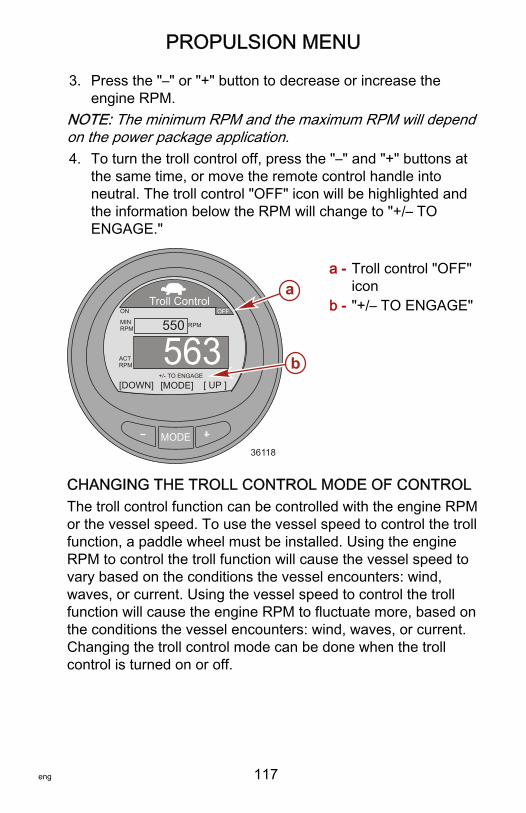
PROPULSION MENU
eng 117
3. Press the "–" or "+" button to decrease or increase theengine RPM.
NOTE: The minimum RPM and the maximum RPM will dependon the power package application.4. To turn the troll control off, press the "–" and "+" buttons at
the same time, or move the remote control handle intoneutral. The troll control "OFF" icon will be highlighted andthe information below the RPM will change to "+/– TOENGAGE."
a - Troll control "OFF"icon
b - "+/– TO ENGAGE"
CHANGING THE TROLL CONTROL MODE OF CONTROLThe troll control function can be controlled with the engine RPMor the vessel speed. To use the vessel speed to control the trollfunction, a paddle wheel must be installed. Using the engineRPM to control the troll function will cause the vessel speed tovary based on the conditions the vessel encounters: wind,waves, or current. Using the vessel speed to control the trollfunction will cause the engine RPM to fluctuate more, based onthe conditions the vessel encounters: wind, waves, or current.Changing the troll control mode can be done when the trollcontrol is turned on or off.
MODE36118
Troll Control
[DOWN] [MODE] [ UP ] +/- TO ENGAGE
OFFON
b
a
MINRPM
ACTRPM 563
550 RPM

PROPULSION MENU
118 eng
1. While the troll control screen is visible, press and hold the"MODE" button until the screen changes mode.
a - RPM modeb - Speed mode
2. Press the "–" or "+" button to change the speed. The engineRPM will react to the selected speed when the troll control isengaged.
3. To change back to the RPM mode, press and hold the"MODE" button until the screen changes from speed modeto the RPM mode.
4. If there is no paddle wheel installed on the vessel, the speedmode of control will show text below the "ACT SPEED"window indicating a paddle wheel is required ("PADDLEREQUIRED").
36530
Troll Control
[DOWN]
ON
[MODE] [ UP ]
SETMPH
MPH PIT 4.5
4.8OFF
ACTSPEED
PADDLE REQUIRED
36529
Troll Control
[DOWN]
ON
[MODE] [ UP ]
SETMPH
MPH PDL 4.5
4.8OFF
+/- TO ENGAGE
ACTSPEED
Troll Control
[DOWN]
ON
[MODE] [ UP ]
MINRPM
ACTRPM 563
550OFF
RPM
+/- TO ENGAGE
a b

PROPULSION MENU
eng 119
Water ScreenThe "Water" screen displays the engine RPM, vessel speedthrough the active sensor, coolant temperature, and waterpressure.
a - RPMb - Vessel speedc - Coolant temperatured - Water pressure
Oil ScreenThe "Oil" screen displays the engine RPM, vessel speed throughthe active sensor, oil temperature, and oil pressure.
a - RPMb - Vessel speedc - Oil temperatured - Oil pressure
MODE36103
RPMSpeed
Coolant TempWater Press
RPM
MPHPDL
oC
Bar
205012.71958.36
Water
[ EXIT ] [ NEXT ]
a
bcd
MODE36105
RPMSpeed
Oil TempOil Press
RPM
MPHPDL
oC
Bar
205012.72052.84
Oil
[ EXIT ] [ NEXT ]
a
bcd
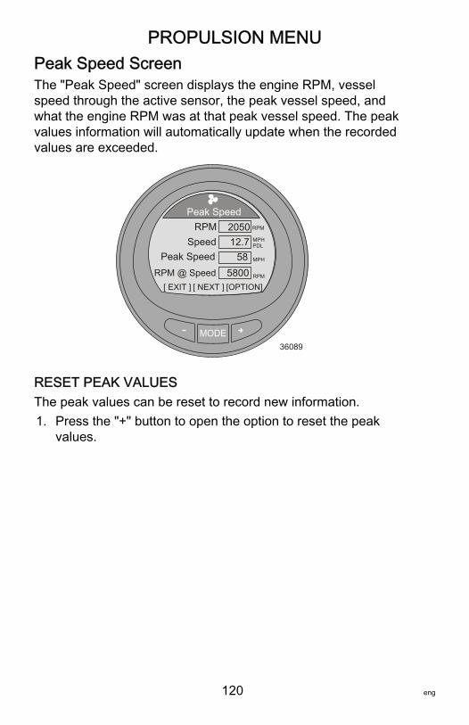
PROPULSION MENU
120 eng
Peak Speed ScreenThe "Peak Speed" screen displays the engine RPM, vesselspeed through the active sensor, the peak vessel speed, andwhat the engine RPM was at that peak vessel speed. The peakvalues information will automatically update when the recordedvalues are exceeded.
MODE36089
RPMSpeed
Peak SpeedRPM @ Speed
RPM
MPHPDL
RPM
205012.7
585800
MPH
[OPTION]
Peak Speed
[ EXIT ] [ NEXT ]
RESET PEAK VALUESThe peak values can be reset to record new information.1. Press the "+" button to open the option to reset the peak
values.
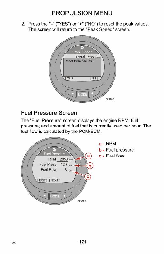
PROPULSION MENU
eng 121
2. Press the "–" ("YES") or "+" ("NO") to reset the peak values.The screen will return to the "Peak Speed" screen.
MODE36092
RPMSpeed
Peak Speed
RPM
MPHPDL
RPM
205012.7
585800
MPH
[ NO ]
Peak Speed
[ YES ]
Reset Peak Values ?
Fuel Pressure ScreenThe "Fuel Pressure" screen displays the engine RPM, fuelpressure, and amount of fuel that is currently used per hour. Thefuel flow is calculated by the PCM/ECM.
a - RPMb - Fuel pressurec - Fuel flow
MODE36093
Fuel Pressure
[ EXIT ] [ NEXT ]
RPMFuel PressFuel Flow
RPM
BAR
205012.7
8 L/H
a
b
c

PROPULSION MENU
122 eng
RPM Synchronize ScreenThe "RPM SYNCH" screen displays the engine RPM and a colorband that expands under the engine with the lower RPM. Thecolor band will decrease in size as the engine RPM's nearsynchronization.
a - Port engine RPMb - Starboard engine
RPMc - Color band
indicatingstarboard engineRPM is low
Engine Location Fuel UseThe engine location fuel use screen shows the engine locationthe gauge is connected to in the upper part of the screen, theamount of fuel that is currently used per hour, and the amount offuel that has been used for that particular engine. The amount offuel used can be reset.
a - Engine locationgauge is connected to
b - Fuel flowc - Fuel used
MODE42342
[ EXIT ] [ NEXT ]
RPM SYNCH
PORT
3750
RPM
3250
STBD
a b
c
MODE36097
STBD
[ EXIT ] [ NEXT ]
Fuel FlowFuel Used
L/H12.78.0 L
a
b
[OPTION]
c

PROPULSION MENU
eng 123
FUEL USED RESET1. Press the "+" button to open the "Fuel Used" reset option.2. Press the "–" ("YES") button to reset the fuel used, or the "+"
("NO") button to return to the fuel use per engine locationscreen.
MODE36098
STBD
[ YES ]
Fuel FlowFuel Used
L/H12.78.0 L
[ NO ]
Fuel Used Reset ?

PROPULSION MENU
124 eng
Double ScreenThe double screen displays two selected data options on anouter and inner display. The outer data will be displayed as a bargraph with a small window that moves with the bar graph leadingedge. The inner data will be displayed as numbers. Options thatcan be selected are; "RPM," "Speed," "Coolant Temp," "OilTemp," "Seatemp," "Water Press," "Oil Press," "Fuel Flow,""Fuel," "Battery," and "Depth." There are five double screensavailable.
a - Moving windowshowing the engineRPM
b - Vessel speed
Analog Tachometer ScreenThe analog tachometer displays the engine RPM with asweeping pointer, simulating a mechanical analog tachometer.
a - Sweeping pointer
MODE42343
0
1
2
34
5
6
7
8
3280
RPM
Speed(MPH)
19.8b
a
MODE42345
0
1
2
34
5
6
7
8RPMX1000
a
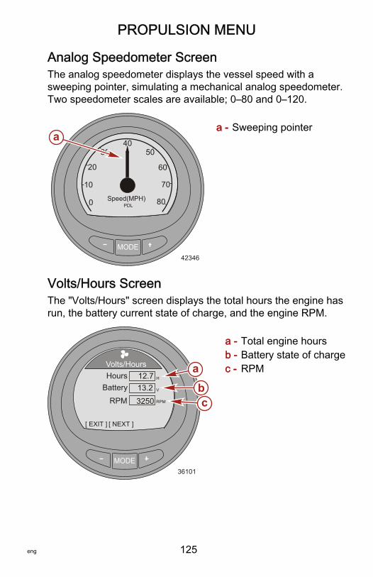
PROPULSION MENU
eng 125
Analog Speedometer ScreenThe analog speedometer displays the vessel speed with asweeping pointer, simulating a mechanical analog speedometer.Two speedometer scales are available; 0–80 and 0–120.
a - Sweeping pointer
Volts/Hours ScreenThe "Volts/Hours" screen displays the total hours the engine hasrun, the battery current state of charge, and the engine RPM.
a - Total engine hoursb - Battery state of chargec - RPM
MODE42346
0
10
20
3040
50
60
70
80Speed(MPH)PDL
a
MODE36101
Volts/Hours
[ EXIT ] [ NEXT ]
HoursBattery
H12.713.2 V
abcRPM RPM3250

PROPULSION MENU
126 eng
Boost Pressure ScreenThe "Boost Pressure" screen displays the engine RPM, thevessel speed through the active sensor, and the amount ofmanifold pressure.
a - RPMb - Vessel speedc - Manifold pressure
Trim Synchronize ScreenThe "Trim Synch" screen displays a color band indicating toincrease or decrease the trim to synchronize the engines trimlocation. The numbers are a point of reference, relating to theposition of the trim outside of the synchronization.
a - Port engine trimpoint of reference
b - Color bandc - Starboard engine
trim point ofreference
MODE36107
Boost Pressure
[ EXIT ] [ NEXT ]
SPEED12.7
MPHPDL
RPM3250
-2 +20
BAR
a b
c
MODE42348
[ EXIT ] [ NEXT ]
TRIM SYNCH
PORT0.0
Trim
3.2STBD
a
b
c

PROPULSION MENU
eng 127
Trim ScreenThe "Trim" screen displays the position of the trim with a movingpropeller icon and displays the trim position number relative tothe propeller icon.
a - Trim indicatorb - Number indicating
the relativeposition
Trim/Tab ScreenThe "Trim/Tab" screen displays the position of the port andstarboard tabs with a moving icon that represents the relativeposition of the tabs. A number below the tab display will indicatethe relative position of the tab. The center of the display willshow the position of the trim with a moving icon that representsthe relative position of the trim. A number below the trim displaywill indicate the relative position of the trim.
a - Port tab indicatorb - Trim indicatorc - Starboard tab
indicatord - Number indicating the
relative position
MODE33230
Trim
[ EXIT ] [ NEXT ]
10
0
25
9.5a
b
MODE36547
Trim/Tab
[ EXIT ] [ NEXT ]
10
0
25
25
STBDPORT
0.0 0.0
ab
c
d
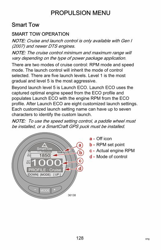
PROPULSION MENU
128 eng
Smart TowSMART TOW OPERATIONNOTE: Cruise and launch control is only available with Gen I(2007) and newer DTS engines.NOTE: The cruise control minimum and maximum range willvary depending on the type of power package application.There are two modes of cruise control: RPM mode and speedmode. The launch control will inherit the mode of controlselected. There are five launch levels. Level 1 is the mostgradual and level 5 is the most aggressive.Beyond launch level 5 is Launch ECO. Launch ECO uses thecaptured optimal engine speed from the ECO profile andpopulates Launch ECO with the engine RPM from the ECOprofile. After Launch ECO are eight customized launch settings.Each customized launch setting name can have up to sevencharacters to identify the custom launch.NOTE: To use the speed setting control, a paddle wheel mustbe installed, or a SmartCraft GPS puck must be installed.
a - Off iconb - RPM set pointc - Actual engine RPMd - Mode of control
MODE36138
SmartTow
[DOWN]
ON
[MODE] [ UP ]
+ / - TO ENGAGE SETRPM
ACTRPM1000
1850OFF
PROFILE : Cruise
bcd
a

PROPULSION MENU
eng 129
1. To engage the "Smart Tow" function, press the "–" and "+"button at the same time. The Smart Tow "ON" icon will behighlighted in the upper left corner and the informationabove the "SET RPM" window will be changed to "+/– TODISENGAGE." When Smart Tow is engaged, the "ON" iconwill remain on and be visible on all of the monitor screens.
a - "ON" iconb - "+/– TO
DISENGAGE"
2. Shift the drive unit into forward gear. The throttle must beabove the set cruise RPM or speed for the Smart Tow cruiseto function. When the throttle is moved below the set cruiseengine RPM or speed, the engine RPM will decrease withthe throttle movement.
3. Press the "–" button to decrease the engine RPM. Press the"+" button to increase the engine RPM.
4. To disengage the "Smart Tow" function, press the "–" and"+" button at the same time. The Smart Tow "OFF" icon willbe highlighted in the upper right corner, and the informationabove the "SET RPM" window will change to "+/– TOENGAGE."
MODE36531
SmartTow
[DOWN] [MODE] [ UP ]
OFF
aST
ONON
[MODE] [ UP ]
+ / - TO DISENGAGE SETRPM
ACTRPM1000
1850OFF
PROFILE : Cruiseb

PROPULSION MENU
130 eng
Changing the Cruise Control ModeThere are two modes of cruise control: RPM mode and speedmode. To use the vessel speed to control the cruise function, apaddle wheel must be installed, or a SmartCraft GPS puck mustbe installed. Using the engine RPM to control the cruise functionwill cause the vessel speed to vary based on the conditions thevessel encounters: wind, waves, or current. Using the vesselspeed to control the cruise function will cause the engine RPM tofluctuate more, based on the conditions the vessel encounters:wind, waves, or current. Changing the cruise control mode canbe done when the troll control is turned on or off.1. To change the mode of cruise control, press and hold the
"MODE" button until the screen changes the mode of cruisecontrol.
a - "ON" iconb - RPM set pointc - Actual engine RPMd - Mode of control
2. The operation of the cruise control in speed mode is thesame as RPM mode. Shift the drive unit into forward gear.The throttle must be above the set cruise speed for the"Smart Tow" cruise to function. When the throttle is movedbelow the set cruise engine speed, the engine RPM willdecrease with the throttle movement.
3. Press the "–" button to decrease the speed. Press the "+"button to increase the speed.
MODE36539
SmartTow
[DOWN] [MODE] [ UP ]
+ / - TO DISENGAGE SETMPH
ACTMPH 33.8
34.0OFF
PROFILE : Cruise
bcd
a
ON ST

PROPULSION MENU
eng 131
4. To disengage the "Smart Tow" function, press the "–" and"+" button at the same time. The Smart Tow "OFF" icon willbe highlighted in the upper right corner and the informationabove the "SET MPH" window will change to "+/– TOENGAGE."
Selecting a Launch Control1. While the "Smart Tow" cruise screen is visible, press the
"MODE" button and an icon of a person skiing will appear onthe profile screen for approximately three seconds.
MODE36144
SmartTow
[DOWN] [MODE] [ UP ]
OFF
PROFILE : Cruise
ONST

PROPULSION MENU
132 eng
2. Press the "–" or "+" button when the profile screen is visibleto advance through or change the launch modes, includingthe ECO Launch and all of the customized launch settings.
MODE36544
SmartTow
[DOWN] [MODE] [ UP ]
ON OFF
PROFILE : Launch 4
ONST
3. After selecting the launch setting, the screen will return tothe "Smart Tow" screen and the selected launch setting willpopulate the lower window.
MODE36545
SmartTow
[DOWN] [MODE] [ UP ]
+ / - TO DISENGAGE SETMPH
ACTMPH 33.8
34.0OFFON
ST
PROFILE : Launch 4
Launch level 4

PROPULSION MENU
eng 133
MODE35710
SmartTow
[DOWN]
ON
[MODE] [ UP ]
+ / - TO ENGAGE SETRPM
ACTRPM2580
2600OFF
PROFILE : Launch ECO
RPM
Launch level ECO
4. To change the launch level, press the "MODE" button andpress the "+" or "–" button to change the launch setting.
5. To change the mode of cruise control, press and hold the"MODE" button until the screen changes the mode of cruisecontrol.
CREATING A CUSTOMIZED LAUNCH SETTINGNOTE: Cruise and launch control is only available with Gen I(2007) and newer DTS engines.NOTE: The cruise control minimum and maximum range willvary depending on the type of power package application.Beyond launch level ECO are eight customized launch settings.Each customized launch setting name can have up to sevencharacters to identify the custom launch. The custom launchsetting can be controlled by RPM or speed. To use the speedsetting control, a paddle wheel must be installed, or a SmartCraftGPS puck must be installed.1. While in the "Main Menu," press the "–" or "+" to highlight
the "Propulsion" menu. Press the "MODE" button to enterthe "Propulsion" menu.
2. Press the "–" or "+" to highlight the "Smart Tow" screen.
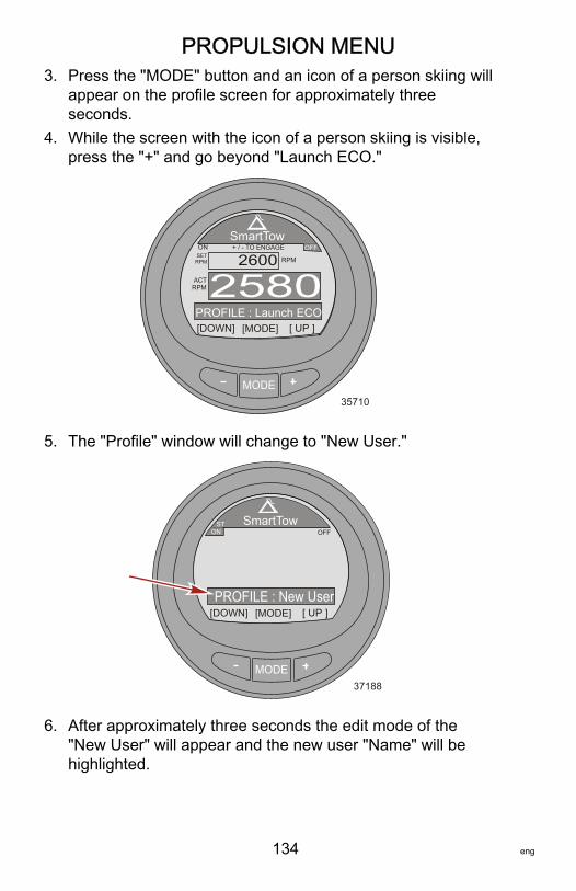
PROPULSION MENU
134 eng
3. Press the "MODE" button and an icon of a person skiing willappear on the profile screen for approximately threeseconds.
4. While the screen with the icon of a person skiing is visible,press the "+" and go beyond "Launch ECO."
MODE35710
SmartTow
[DOWN]
ON
[MODE] [ UP ]
+ / - TO ENGAGE SETRPM
ACTRPM2580
2600OFF
PROFILE : Launch ECO
RPM
5. The "Profile" window will change to "New User."
MODE37188
SmartTow
[DOWN] [MODE] [ UP ]
ON OFF
PROFILE : New User
ONST
6. After approximately three seconds the edit mode of the"New User" will appear and the new user "Name" will behighlighted.
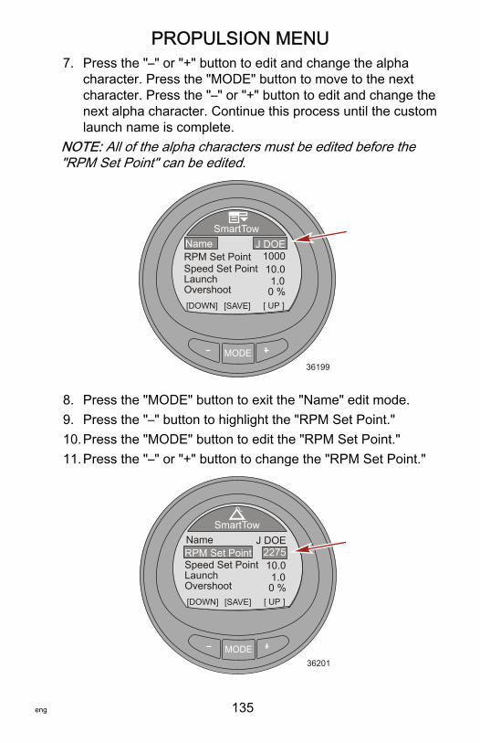
PROPULSION MENU
eng 135
7. Press the "–" or "+" button to edit and change the alphacharacter. Press the "MODE" button to move to the nextcharacter. Press the "–" or "+" button to edit and change thenext alpha character. Continue this process until the customlaunch name is complete.
NOTE: All of the alpha characters must be edited before the"RPM Set Point" can be edited.
MODE36199
SmartTow
[DOWN] [SAVE] [ UP ]
1000NameRPM Set Point
J DOE
Speed Set PointLaunchOvershoot
10.01.00 %
8. Press the "MODE" button to exit the "Name" edit mode.9. Press the "–" button to highlight the "RPM Set Point."10.Press the "MODE" button to edit the "RPM Set Point."11.Press the "–" or "+" button to change the "RPM Set Point."
MODE36201
SmartTow
[DOWN] [SAVE] [ UP ]
NameRPM Set Point
J DOE
Speed Set PointLaunchOvershoot
10.01.00 %
2275

PROPULSION MENU
136 eng
12.Press the "MODE" button to exit the "RPM Set Point" mode.13.Press the "–" button to highlight the "Speed Set Point."14.Press the "MODE" button to edit the "Speed Set Point."15.Press the "–" or "+" button to change the "Speed Set Point."
MODE36202
SmartTow
[DOWN] [SAVE] [ UP ]
NameRPM Set Point
J DOE
Speed Set PointLaunchOvershoot
10.01.00 %
2275
16.Press the "MODE" button to exit the "Speed Set Point"mode.
17.Press the "–" button to highlight "Launch."18.Press the "MODE" button to edit "Launch."19.Press the "–" or "+" button to change the "Launch" setting.
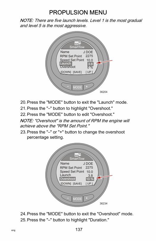
PROPULSION MENU
eng 137
NOTE: There are five launch levels. Level 1 is the most gradualand level 5 is the most aggressive.
MODE36204
SmartTow
[DOWN] [SAVE] [ UP ]
NameRPM Set Point
J DOE
Speed Set PointLaunchOvershoot
10.03.80 %
2275
20.Press the "MODE" button to exit the "Launch" mode.21.Press the "–" button to highlight "Overshoot."22.Press the "MODE" button to edit "Overshoot."NOTE: "Overshoot" is the amount of RPM the engine willachieve above the "RPM Set Point."23.Press the "–" or "+" button to change the overshoot
percentage setting.
MODE36234
SmartTow
[DOWN] [SAVE] [ UP ]
NameRPM Set Point
J DOE
Speed Set PointLaunchOvershoot
10.03.8
10 %
2275
24.Press the "MODE" button to exit the "Overshoot" mode.25.Press the "–" button to highlight "Duration."

PROPULSION MENU
138 eng
26.Press the "MODE" button to edit "Duration."NOTE: "Duration" is the amount of time the engine RPM"Overshoot" will be allowed.IMPORTANT: The RPM and speed setpoints will change to thelast setpoint used for that particular new user when using SmartTow.27.Press the "–" or "+" button to change the duration seconds.
MODE36236
SmartTow
[DOWN] [EDIT] [ UP ]ExitDuration
Speed Set PointLaunchOvershoot
10.03.8
10 %3.8 s
28.Press the "MODE" button to exit the "Duration" mode.29.Press the "–" button to highlight the "Exit" option.30.Press the "MODE" button to exit the custom launch mode.
VESSEL MENU
eng 139
Using the Vessel ScreensThe vessel menu screens will display information concerning thevessel and associated systems. Screens that are available in thevessel menu may vary according to the engine type, but mayinclude the following:• Economy (ECO)• Trip data• Generator dataNOTE: The generator must be capable of sending data on acontrol area network.• Range• Trim• Fuel tank1• Tank 2• Tabs• GPS information• Waypoint information• Steering position• Depth

VESSEL MENU
140 eng
Available Vessel Screens
Economy(ECO)
The software for the economyscreen monitors the enginesensors and looks for the best fueleconomy number while runningthe boat. When the softwarerecognizes an improvement in thefuel economy, the gauge recordswhat the trim and engine RPMvalues are at that time. Thiscalculation happens whether theECO screen is visible or not.When the software has recordedthe RPM and trim values, it willguide the operator with arrows, towhere that optimum runningspeed and trim setting was. TheECO screen does not need anycalibration, although there aresettings to customize the gaugefor your boating style. Theeconomy screen optimized valuescan be reset.
[ EXIT ] [ NEXT ] [OPTION]
OKOK
OPTIMIZEDECONOMY
10 7
4
10
5 M/G
MPH
RPM
3.63450
24.3
42352
TRIM RPM
Trip Data
Displays the vessel speed throughthe available sensor, the currenttrip distance, the total amount offuel used, and the current amountof time during the trip. Thedistance, fuel used, and time canbe reset.
Total Used
SpeedTrip Dist
Trip Time
MI
MPHPDL
H
30.512.75.85.0
GAL
[OPTION]
Trip Data
[ EXIT ] [ NEXT ]36558
Generator
Displays the AC voltage, the hertzfrequency, the generator locationor name, and the generatorrunning hours. The generator unitmust be interfaced with the CANcommunication for this option todisplay information. [ NEXT ]
Generator
[ EXIT ]
GENERATOR - - - - - -
36613
OHOURS
OAC-VOLTAGE
OFREQUENCY

VESSEL MENU
eng 141
Range
Displays the current amount offuel economy, the averageamount of fuel used, theestimated distance the vessel cantravel based on the current usage,and the total amount of fuel used.The average fuel used and thetotal amount used can be reset.
[ NEXT ]
Range
[ EXIT ]36616
M/G- - -
[OPTION]
Inst.Average
Est. RangeTot. Used
MI
M/G
GAL
0.0- - -0.0
Trim
Displays a number relating to theposition of the trim system, theengine water pressure, and theengine RPM.
[ NEXT ]
Trim
[ EXIT ]36631
TrimWater Press
RPM RPM
PSI0.025
0
Fuel Tank1
Displays the level of the fuel tank,the location of the fuel tank, andwill display "FAULT" when there isa problem with the fuel tank. It canalso be selected as not installed("Not inst"). When selected as notinstalled, the "Fuel Tank 1" screenwill not be accessible.
[ NEXT ]
Fuel Tank1
[ EXIT ]36635
FAULTE
F
STBD
Tank 2
Tank 2 can be selected as notinstalled, fuel, water, or wastewhen connected to a 4‑Strokeengine. When selected as fuel,the level can be calibrated with adefault setting, or by adding fuel.When selected as water or waste,the level is calibrated to thedefault setting.
[ NEXT ]
Water Tank
[ EXIT ]36637
E
F
STBD
0%

VESSEL MENU
142 eng
TabsDisplays the position of the tabswith numbers and a bar graph foreach tab.
Tabs
[ EXIT ] [ NEXT ]36731
STBDPORT
0.0 0.0
GPS
Displays the course over ground("COG"), speed over ground("SOG"), latitude position ("LAT"),and longitude position (LON"). AGPS must be installed for thisoption to display information. [ NEXT ]
GPS
[ EXIT ]36642
COGSOGLATLON
O
- - - - - -
- - - - - -
MPH
To Waypoint
Displays the amount of time to thewaypoint, the compass bearingtowards the waypoint, thedistance to the waypoint, and theamount of fuel required to thewaypoint. A GPS must beinstalled with a SmartCraft puckfor this option to displayinformation.
[ NEXT ]
To Waypoint
[ EXIT ]36645
TimeBearing
DistFuel
H
- - - - - -
- - - - - -
o
MI
GAL
Steering
Displays the engine RPM, thevessel speed, a bar graphindicating the direction of thesteering ("PORT" or "STBD"), anda number displayed to indicate therelative position of the steering. Asteering position sensor must beinstalled for this screen to displaythe steering direction and relativeposition.
[ NEXT ]
Steering
[ EXIT ]36647
PORT
SPEED MPHPDL
RPM
STBD
0 0.0
49o

VESSEL MENU
eng 143
Depth
Displays the depth of the water,the temperature of the water, andthe speed of the vessel throughthe active sensor.
[ NEXT ]
Depth
[ EXIT ]36650
MPHPDL
FT
- - - 0.0
- - - Fo
DepthSeatemp
Speed
Maintenance
Power packages capable ofdetermining the life of the engineoil will have a maintenancescreen. The maintenance screendisplays a bar graph representingthe percent of life that remains inthe engine oil. The life of the oil isestimated by the engine ECM/PCM. The RPM and load on theengine will affect how quickly theengine oil life bar graph changes.
33229[ NEXT ]
Maintenance
[ EXIT ]
Engine Oil Life
[RESET]
0 100%
89%
OK
Economy (ECO) ScreenThe economy screen monitors the engine sensors and looks forthe best fuel economy number while the vessel is under way.When the software recognizes an improvement in the fueleconomy, the gauge records what the trim and engine RPMvalues are at that time. This calculation happens whether theECO screen is visible or not. When the software has recordedthe RPM and trim values, it will guide the operator with arrows towhere that optimum running speed and trim setting was. TheECO screen does not need any calibration, although there aresettings to customize the gauge for your boating style. Thedefault settings are within acceptable parameters for most vesselapplications.

VESSEL MENU
144 eng
When the economy screen is "OPTIMIZED," the backlighting ofthe screen will turn to green. While "OPTIMIZED," the trim andRPM arrows with be aligned with the economy target windows.When either the trim or RPM arrows are outside the targetwindow, the arrows will become hollow and the backlighting willturn to yellow. These color changes are difficult to identify in thesunlight. The target windows can be made smaller or larger. Themenu path to change the target window size is: "Settings," >"ECO," > "Trim Accuracy [%]" for trim, or "RPM Accuracy [%]" forRPM. The default number of 4 is generally a good setting formost vessel configurations. The higher the number, the largerthe target window.
a - Trim targetwindow
b - Economyoptimized
c - Fuel economyd - RPM target
windowe - RPMf - Vessel speed
MODE
[EXIT] [NEXT] [REFRESH]
OKOK
OPTIMIZEDECONOMY
10 5
20
5 M/G
MPH
RPM
3.63450
24.3TRIM RPM
ad
b
c
e
f
42354

VESSEL MENU
eng 145
• If the software has recorded an economy value that is betterthan where you are currently, the screen will show "NOTOPTIMIZED" at the top of the screen and the backlightingwill turn to the color yellow. This color change is difficult toidentify in the sunlight. The trim position arrow will becomehollow, a guide arrow will appear indicating the trim positionmust be changed either up or down, and the recorded targetwindow will appear in a new location. Pressing the refreshbutton "+" ("REFRESH") at any time while the economyscreen is visible will restart the economy calculations.
a - New recordedtarget window
b - Hollow arrowc - Guide arrow
indicating directionchange
d - Screen showing"NOTOPTIMIZED"
• When the trim target is achieved, the trim position arrow willno longer be hollow, and "OK" will replace the guide arrow.
a - Trim position arrownot hollow
b - "OK" replaces guidearrow
MODE
[ EXIT ] [ NEXT ] [REFRESH]
TRIM
OPTIMIZED10 5
20
5 M/G
MPH
RPM
3.63450
24.3TRIM RPM
a
b
c
42355
RPM
NOTECONOMY
d
MODE
[ EXIT ] [ NEXT ] [REFRESH]
OPTIMIZED10 5
20
5 M/G
MPH
RPM
3.63450
24.3TRIM RPM
b
a
42358
RPM
NOTECONOMY
OK

VESSEL MENU
146 eng
• The RPM position arrow will become hollow, a guide arrowwill appear indicating the RPM must be raised or lowered,and the recorded target window will appear in a newlocation.
a - Guide arrowindicating directionchange
b - Hollow arrowc - New recorded
target window
• When the RPM target is achieved, the RPM arrow will nolonger be hollow, and "OK" will replace the guide arrow. Thescreen will change color from yellow to green indicating theengine is at the optimized running RPM and trim position.The color change is difficult to identify in the sunlight.
a - "OK" replacesguide arrow
b - Trim position arrownot hollow
c - New recordedtarget window
MODE
[ EXIT ] [ NEXT ] [REFRESH]
OPTIMIZED10 5
20
5 M/G
MPH
RPM
3.13350
22.3TRIM RPM
ab
42360
RPM
NOTECONOMY
OK c
MODE
[ EXIT ] [ NEXT ] [REFRESH]
OPTIMIZED10 5
20
5 M/G
MPH
RPM
4.23275
21.8TRIM RPM
ab
42361
ECONOMY
OK cOK

VESSEL MENU
eng 147
• If the RPM exceeds the maximum selected RPM in the"Settings" menu, the screen will change color and advised todecrease the RPM below the selected RPM.
a - Decrease RPM screen
• To change the maximum selected RPM, go to the economyscreen in the "Settings" menu. The menu path is: "Settings,"> "ECO," > "Max RPM." The default setting is 4300.
MODE
ECO
42294
Trim Accuracy[%] [DOWN] [EDIT]
Min. RPMMax. RPM
MPG timeRPM time
23004300
0.74
0.7
[ UP ]
MODE
RPM10 5
20
5 M/G
MPH
RPM
1.94890
33.1TRIM RPM
a
42363
ECONOMYDECREASE
[ EXIT ] [ NEXT ] [REFRESH]

VESSEL MENU
148 eng
• If the RPM drops below the minimum selected RPM in the"Settings" menu, the screen will change color and advised toincrease the RPM above the selected RPM.
a - Increase RPM screen
• To change the minimum selected RPM, go to the economyscreen in the "Settings" menu. The menu path is: "Settings,"> "ECO," > "Min RPM." The default setting is 2300 RPM.
MODE
ECO
42291
Trim Accuracy[%] [DOWN] [EDIT]
Min. RPMMax. RPM
MPG timeRPM time
23004300
0.74
0.7
MODE
RPM10 5
20
5 M/G
MPH
RPM
2.11205
5.0TRIM RPM
a
42365
ECONOMYINCREASE
[ EXIT ] [ NEXT ] [REFRESH]

VESSEL MENU
eng 149
ECONOMY RESET• To recalculate the RPM and trim targets, press the
"REFRESH" ("+") button. The gauge software will calculatethe targets for the maximum economy.
a - "REFRESH" ("+")button
Trip Data ScreenThe "Trip Data" screen displays the current vessel speed. Thisdata is based on which sensor is active; pitot sensor, paddlewheel, or GPS. The type of speed sensor is displayed on theright side of the "Speed" information window. When the transitionspeed is reached, the new active speed sensor will then bedisplayed.The trip distance ("Trip Dist") will display how far the vessel hastraveled. The trip distance can be reset.The total fuel used ("Total Used") is the total of all the enginesrunning on the vessel, displaying how much fuel has been useddown to a tenth of the unit. The total fuel used can be reset.
MODE
RPM10 5
20
5 M/G
MPH
RPM
1.94890
33.1TRIM RPM
a
42367
ECONOMYDECREASE
[ EXIT ] [ NEXT ] [REFRESH]
Recalculate ECOValues ?
Current values are:Trim - 5 RPM - 2300Peak Fuel M/G - 3.9
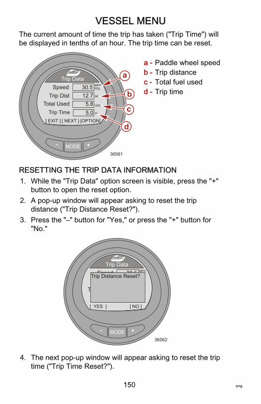
VESSEL MENU
150 eng
The current amount of time the trip has taken ("Trip Time") willbe displayed in tenths of an hour. The trip time can be reset.
a - Paddle wheel speedb - Trip distancec - Total fuel usedd - Trip time
RESETTING THE TRIP DATA INFORMATION1. While the "Trip Data" option screen is visible, press the "+"
button to open the reset option.2. A pop‑up window will appear asking to reset the trip
distance ("Trip Distance Reset?").3. Press the "–" button for "Yes," or press the "+" button for
"No."
MODE36562
Total Used
SpeedTrip Dist
Trip Time
MI
MPHPDL
H
30.512.75.85.0
GAL
[ NO ]
Trip Data
[ YES ]
Trip Distance Reset?
4. The next pop‑up window will appear asking to reset the triptime ("Trip Time Reset?").
MODE36561
Total Used
SpeedTrip Dist
Trip Time
MI
MPHPDL
H
30.512.75.85.0
GAL
[OPTION]
Trip Data
[ EXIT ] [ NEXT ]
a
b
c
d
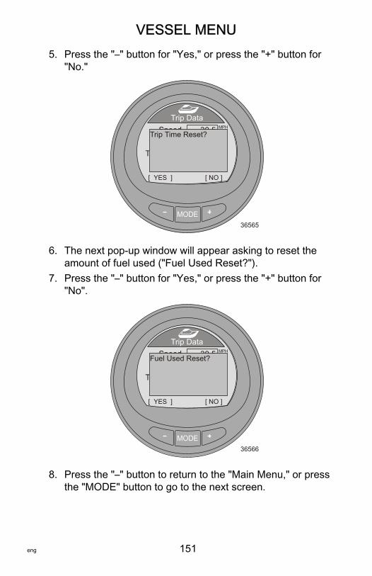
VESSEL MENU
eng 151
5. Press the "–" button for "Yes," or press the "+" button for"No."
MODE36565
Total Used
SpeedTrip Dist
Trip Time
MI
MPHPDL
H
30.512.75.85.0
GAL
[ NO ]
Trip Data
[ YES ]
Trip Time Reset?
6. The next pop‑up window will appear asking to reset theamount of fuel used ("Fuel Used Reset?").
7. Press the "–" button for "Yes," or press the "+" button for"No".
MODE36566
Total Used
SpeedTrip Dist
Trip Time
MI
MPHPDL
H
30.512.75.85.0
GAL
[ NO ]
Trip Data
[ YES ]
Fuel Used Reset?
8. Press the "–" button to return to the "Main Menu," or pressthe "MODE" button to go to the next screen.
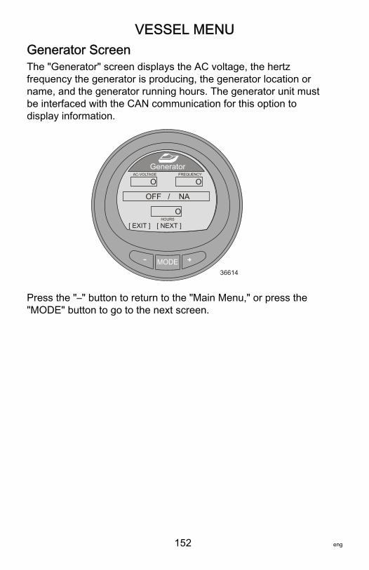
VESSEL MENU
152 eng
Generator ScreenThe "Generator" screen displays the AC voltage, the hertzfrequency the generator is producing, the generator location orname, and the generator running hours. The generator unit mustbe interfaced with the CAN communication for this option todisplay information.
MODE36614
[ NEXT ]
Generator
[ EXIT ]
OFF / NA
OHOURS
OAC-VOLTAGE
OFREQUENCY
Press the "–" button to return to the "Main Menu," or press the"MODE" button to go to the next screen.
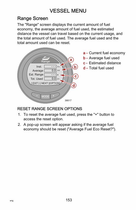
VESSEL MENU
eng 153
Range ScreenThe "Range" screen displays the current amount of fueleconomy, the average amount of fuel used, the estimateddistance the vessel can travel based on the current usage, andthe total amount of fuel used. The average fuel used and thetotal amount used can be reset.
a - Current fuel economyb - Average fuel usedc - Estimated distanced - Total fuel used
RESET RANGE SCREEN OPTIONS1. To reset the average fuel used, press the "+" button to
access the reset option.2. A pop‑up screen will appear asking if the average fuel
economy should be reset ("Average Fuel Eco Reset?").
MODE36617
[ NEXT ]
Range
[ EXIT ]
M/G- - -
[OPTION]
Inst.Average
Est. RangeTot. Used
MI
M/G
GAL
0.0- - -0.0
a
b
c
d
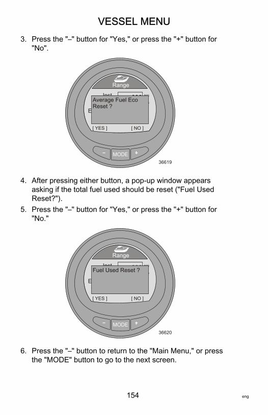
VESSEL MENU
154 eng
3. Press the "–" button for "Yes," or press the "+" button for"No".
MODE36619
Range
[ YES ]
M/G- - -
[ NO ]
Inst.
Est. RangeTot. Used
MI
M/G
GAL
0.0- - -0.0
Average Fuel EcoReset ?
4. After pressing either button, a pop‑up window appearsasking if the total fuel used should be reset ("Fuel UsedReset?").
5. Press the "–" button for "Yes," or press the "+" button for"No."
MODE36620
Range
[ YES ]
M/G- - -
[ NO ]
Inst.
Est. RangeTot. Used
MI
M/G
GAL
0.0- - -0.0
Fuel Used Reset ?
6. Press the "–" button to return to the "Main Menu," or pressthe "MODE" button to go to the next screen.

VESSEL MENU
eng 155
Trim ScreenThe "Trim" screen displays a number relating to the position ofthe trim system, the engine water pressure, and the engineRPM.
a - Trim position numberb - Water pressurec - Engine RPM
Press the "–" button to return to the "Main Menu," or press the"MODE" button to go to the next screen.
MODE36632
[ NEXT ]
Trim
[ EXIT ]
TrimWater Press
RPM RPM
PSI0.025
0
ab
c

VESSEL MENU
156 eng
TanksFUEL TANK 1The "Fuel Tank 1" screen displays the level of the fuel tank, thelocation of the fuel tank, and will display "FAULT" when there is aproblem with the fuel tank. It can also be selected as notinstalled ("Not inst"). When selected as not installed, the "FuelTank 1" screen will not be accessible.
a - Fuel tank fault("FAULT")
b - Fuel levelc - Tank location
TANK 2"Tank 2" can be selected as not installed ("Not inst"), fuel, water,or waste when connected to a four‑stroke engine. When selectedas fuel, the level can be calibrated with a default setting, or byadding fuel. When selected as water or waste, the level isautomatically calibrated to the default setting.
MODE36636
[ NEXT ]
Fuel Tank1
[ EXIT ]
FAULTE
F
STBD
ab
c

VESSEL MENU
eng 157
When the gauge is installed on a vessel with a two‑strokeengine, "Tank 2" will automatically default to oil.
a - Tank levelpercentage
b - Tank typec - Tank leveld - Tank location
Press the "–" button to return to the "Main Menu," or press the"MODE" button to go to the next screen.
Tabs ScreenThe "Tabs" screen displays the port tab and starboard tabposition with a bar graph and numbers.
a - Port tab bar graphb - Starboard tab bar
graphc - Bar graph pointerd - Tab position number
Press the "–" button to return to the "Main Menu," or press the"MODE" button to go to the next screen.
MODE36638
[ NEXT ]
Water Tank
[ EXIT ]E
F
STBD
0%
a
b
c
d
MODE36900
Tabs
[ EXIT ] [ NEXT ]
STBDPORT
0.0 0.0
bac
d

VESSEL MENU
158 eng
GPS ScreenThe "GPS" screen displays the course over ground ("COG"),speed over ground ("SOG"), latitude position ("LAT"), andlongitude position ("LON"). A GPS must be installed for thisoption to display information.
a - Course over ground("COG")
b - Speed over ground("SOG")
c - Latitude position("LAT")
d - Longitude position(LON")
Press the "–" button to return to the "Main Menu," or press the"MODE" button to go to the next screen.
MODE36643
[ NEXT ]
GPS
[ EXIT ]
COGSOGLATLON
O
- - - - - -
- - - - - -
MPH
a
b
c
d

VESSEL MENU
eng 159
To Waypoint ScreenThe "To Waypoint" screen displays the amount of time requiredto reach the waypoint, the compass bearing towards thewaypoint, the distance to the waypoint, and the amount of fuelrequired to the waypoint. A GPS and chart plotter or a devicecapable of generating waypoints must be installed for this optionto display information.
a - Timeb - Compass bearingc - Distanced - Fuel
Press the "–" button to return to the "Main Menu," or press the"MODE" button to go to the next screen.
MODE36646
[ NEXT ]
To Waypoint
[ EXIT ]
TimeBearing
DistFuel
H
- - - - - -
- - - - - -
o
MI
GAL
a
b
c
d

VESSEL MENU
160 eng
Steering ScreenThe "Steering" screen displays the engine RPM, the vesselspeed, a bar graph indicating the direction of the steering("PORT" or "STBD"), and a number displayed to indicate therelative position of the steering. A steering position sensor mustbe installed for this screen to display the steering direction andrelative position.
a - Engine RPMb - Vessel speedc - Steering bar graphd - Relative position of
the steering
Press the "–" button to return to the "Main Menu," or press the"MODE" button to go to the next screen.
MODE36648
[ NEXT ]
Steering
[ EXIT ]PORT
SPEED MPHPDL
RPM
STBD
0 0.0
49o
a b
c
d
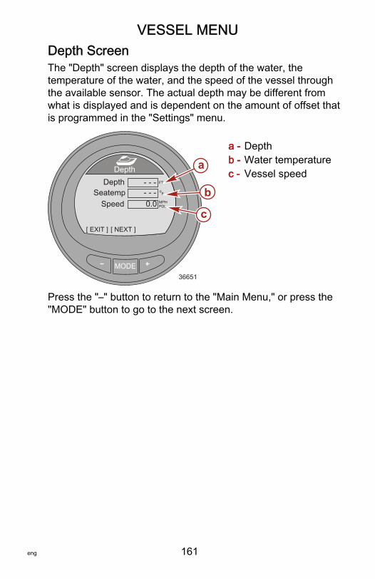
VESSEL MENU
eng 161
Depth ScreenThe "Depth" screen displays the depth of the water, thetemperature of the water, and the speed of the vessel throughthe available sensor. The actual depth may be different fromwhat is displayed and is dependent on the amount of offset thatis programmed in the "Settings" menu.
a - Depthb - Water temperaturec - Vessel speed
Press the "–" button to return to the "Main Menu," or press the"MODE" button to go to the next screen.
MODE36651
[ NEXT ]
Depth
[ EXIT ]
MPHPDL
FT
- - - 0.0
- - - Fo
DepthSeatemp
Speed
a
b
c
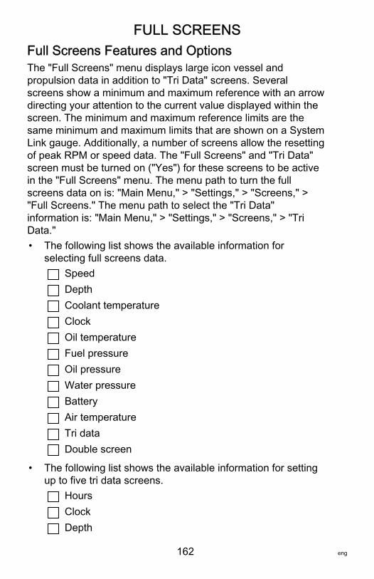
FULL SCREENS
162 eng
Full Screens Features and OptionsThe "Full Screens" menu displays large icon vessel andpropulsion data in addition to "Tri Data" screens. Severalscreens show a minimum and maximum reference with an arrowdirecting your attention to the current value displayed within thescreen. The minimum and maximum reference limits are thesame minimum and maximum limits that are shown on a SystemLink gauge. Additionally, a number of screens allow the resettingof peak RPM or speed data. The "Full Screens" and "Tri Data"screen must be turned on ("Yes") for these screens to be activein the "Full Screens" menu. The menu path to turn the fullscreens data on is: "Main Menu," > "Settings," > "Screens," >"Full Screens." The menu path to select the "Tri Data"information is: "Main Menu," > "Settings," > "Screens," > "TriData."• The following list shows the available information for
selecting full screens data.SpeedDepthCoolant temperatureClockOil temperatureFuel pressureOil pressureWater pressureBatteryAir temperatureTri dataDouble screen
• The following list shows the available information for settingup to five tri data screens.
HoursClockDepth

FULL SCREENS
eng 163
RPMSpeedCoolant temperatureOil temperatureSeawater temperatureWater pressureOil pressureTrimFuel flowBatteryFuel
RPM
Displays large numbers for theengine RPM, shows the peakspeed, and the peak RPM atspeed. The peak values can bereset.
[ NEXT ]
RPM
[ EXIT ]36680
0RPM
[OPTION]RPM AT SPEED PEAK MPH
0.0 0
Speed
Displays large numbers for thevessel speed through theavailable sensor, the peakspeed, and the peak RPM atspeed. The peak values can bereset. [ NEXT ]
Speed
[ EXIT ]36681
0.0MPH
[OPTION]RPM AT SPEED PEAK MPH
0.0 0
PDL
BatteryDisplays the battery voltagelevel in large numbers and on abar graph.
39286[ NEXT ]
Battery
[ EXIT ]8
13.816
V

FULL SCREENS
164 eng
Depth Displays the water depth inlarge numbers.
[ NEXT ]
Depth
[ EXIT ]36685
126 FT
CoolantTemperature
Displays the engine coolanttemperature in large numbersand on a bar graph.
39290[ NEXT ]
Coolant Temp
[ EXIT ]0
177200
Fo
OilTemperature
Displays the engine oiltemperature in large numbersand on a bar graph.
39751[ NEXT ]
Oil Temp
[ EXIT ]0
177300
Fo
Fuel Pressure Displays the engine fuelpressure in large numbers.
[ NEXT ]
Fuel Pressure
[ EXIT ]36697
42.8 PSI
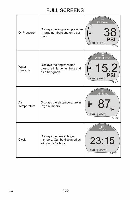
FULL SCREENS
eng 165
Oil PressureDisplays the engine oil pressurein large numbers and on a bargraph.
39752[ NEXT ]
Oil Press
[ EXIT ]0
38100
PSI
WaterPressure
Displays the engine waterpressure in large numbers andon a bar graph.
40531[ NEXT ]
Water Press
[ EXIT ]0
15.230
PSI
AirTemperature
Displays the air temperature inlarge numbers.
43149[ NEXT ]
Air Temp
[ EXIT ]
87FO
ClockDisplays the time in largenumbers. Can be displayed as24 hour or 12 hour.
[ NEXT ]
Clock
[ EXIT ]36702
23:15
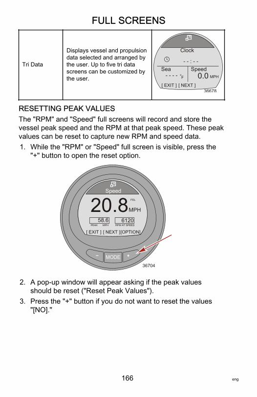
FULL SCREENS
166 eng
Tri Data
Displays vessel and propulsiondata selected and arranged bythe user. Up to five tri datascreens can be customized bythe user.
[ NEXT ]
Clock
[ EXIT ]36678
SpeedSea- - : - -
- - - - Fo 0.0 MPH
RESETTING PEAK VALUESThe "RPM" and "Speed" full screens will record and store thevessel peak speed and the RPM at that peak speed. These peakvalues can be reset to capture new RPM and speed data.1. While the "RPM" or "Speed" full screen is visible, press the
"+" button to open the reset option.
MODE36704
[ NEXT ]
Speed
[ EXIT ]
20.8MPH
[OPTION]RPM AT SPEED PEAK MPH
58.6 6120
PDL
2. A pop‑up window will appear asking if the peak valuesshould be reset ("Reset Peak Values").
3. Press the "+" button if you do not want to reset the values"[NO]."

FULL SCREENS
eng 167
4. Press the "–" button if you want to reset the values "[YES]."
MODE36706
Speed
[ YES ]
20.8MPH
[ NO ]RPM AT SPEED PEAK MPH
58.6 6120
PDLReset Peak Values ?
5. When the selection is "[YES]," the pop‑up window will closeand the new data will populate the peak values immediately.
Maintenance ScreenPower packages capable of determining the life of the engine oilwill have a maintenance screen. The maintenance screendisplays a bar graph representing the percent of life that remainsin the engine oil. The life of the oil is estimated by the engineECM/PCM. Specific bands of RPM, and heavy thrust loads onthe engine, are factors on how quickly the engine oil life bargraph changes. The software is based on tests conducted with aMercury Quicksilver lubricant. Use common sense to protectyour investment and check your engine oil on a regular basis,preferably before each use.1. While in the "Main Menu," use the "–" or "+" button to
highlight the "Full Screens" option. Press "MODE" to openthe "Full Screens" option.
2. Press the "MODE" button to page through the screens.

FULL SCREENS
168 eng
3. The "Maintenance" screen will show the percentage of liferemaining in the engine oil and a bar graph representing thesame percentage. Press the "–" to exit to the "Main Menu,""MODE" to go to the next screen, or "+" to reset the engineoil life.
MODE35698
[ NEXT ]
Maintenance
[ EXIT ]
Engine Oil Life
[RESET]
0 100%
89%
OK
4. The "Engine Oil Life" should be reset after changing theengine oil and filter. Press the "+" button to reset the"Maintenance Engine Oil Life."

FULL SCREENS
eng 169
5. A window will pop up asking "HAS YOUR ENGINE OILBEEN CHANGED?" Press the "MODE" button ("NO") toreturn to the "Maintenance" screen, or press "–" button("YES") to reset the "Engine Oil Life" screen.
MODE35699
[ NO ]
Maintenance
[ YES ]
Engine Oil Life0 100%
89%
OKHAS YOUR ENGINE OILBEEN CHANGED?
6. When the life of the engine oil is less than 10 percent, the"OK" icon will change to a wrench. The wrench iconindicates the engine oil and filter should be replaced. Pressthe "–" button to return to the "Maintenance" screen, pressthe "MODE" button to page through the "Full Screens" orpress the "+" button after changing the engine oil and filter toreset the "Engine Oil Life" screen.
MODE35700
[NEXT]
Maintenance
Engine Oil Life0 100%
5%
[EXIT] [RESET]
a
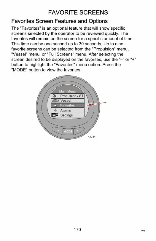
FAVORITE SCREENS
170 eng
Favorites Screen Features and OptionsThe "Favorites" is an optional feature that will show specificscreens selected by the operator to be reviewed quickly. Thefavorites will remain on the screen for a specific amount of time.This time can be one second up to 30 seconds. Up to ninefavorite screens can be selected from the "Propulsion" menu,"Vessel" menu, or "Full Screens" menu. After selecting thescreen desired to be displayed on the favorites, use the "–" or "+"button to highlight the "Favorites" menu option. Press the"MODE" button to view the favorites.
MODE
Main MenuPropulsion / STVessel
42344
SettingsAlarms!
Favorites

FAVORITE SCREENS
eng 171
SELECTING A FAVORITE SCREEN1. From the "Main Menu," press the "–" or "+" button to select
either the "Propulsion," "Vessel," or "Full Screens" menu.
MODE
Main MenuPropulsion / ST
FavoritesVessel
42337
Alarms!Settings
2. Press the "MODE" button to enter the selected menu.3. Press the "–" or "+" button and select a screen to be a
favorite.
MODE36089
RPMSpeed
Peak SpeedRPM @ Speed
RPM
MPHPDL
RPM
205012.7
585800
MPH
[OPTION]
Peak Speed
[ EXIT ] [ NEXT ]

FAVORITE SCREENS
172 eng
4. Press the "–" button and the "+" button at the same time andhold the buttons in until the pop‑up window appears askingto add the screen to the favorites ("Add to Favorites?").
MODE36744
RPMSpeed
Peak SpeedRPM @ Speed
RPM
MPHPDL
RPM
205012.7
585800
MPH
[ YES ]
Peak Speed
[ NO ]
Add to Favorites ?
5. Press the "+" button to save the screen to the "Favorites"menu. If the screen is not wanted, press the "–" button todiscard the screen option.
6. Press the "MODE" button to page through the menu toselect a different screen, or press the "–" button to exit themenu and return to the "Main Menu."
7. Continue the selection process for up to nine selectedfavorites.
CHANGING THE FAVORITES SCREEN DURATIONThe favorites individual screen will remain visible for a specificamount of time. This time can be set from one second up to 30seconds.

FAVORITE SCREENS
eng 173
1. To change the favorites screen duration, go to the "MainMenu" and press the "–" or "+" button to highlight the"Settings" menu.
MODE
Main MenuPropulsion / ST
FavoritesVessel
33077
SettingsAlarms!
2. Press the "MODE" button to enter the "Settings" menu.3. Press the "–" button to highlight the "Screens" menu.
MODE
Settings
42175
TanksTrim
[DOWN] [EDIT]
Light/ContrastUnits
[ UP ]
Screens
4. Press the "MODE" button to enter the "Screens" menu.5. Press the "–" or "+" button to highlight the "Favorites Slide"
option.6. Press the "MODE" button to edit the number of seconds the
favorites will display.

FAVORITE SCREENS
174 eng
7. Press the "–" or "+" button to change the number ofseconds.
MODE
Screens
33076
[DOWN] [EDIT]
Screen SyncFavorites Slide
[ UP ]
SmartTow
Yes
Exit
Generator No
2s
Yes
DELETING A FAVORITE1. Select the screen that is to be deleted.2. Press the "–" button and the "+" button at the same time and
hold the buttons in until the pop‑up window appears askingto remove the screen from the favorites ("Remove fromFavorites?").
MODE36943
RPMSpeed
Peak SpeedRPM @ Speed
RPM
MPHPDL
RPM
205012.7
585800
MPH
[ YES ]
Peak Speed
[ NO ]
Remove from Favorites?

FAVORITE SCREENS
eng 175
3. Press the "+" button to remove the screen from the"Favorites" menu. Press the "–" button to keep the screen asa favorite.
4. Press the "MODE" button to page through the menu toselect a different screen, or press the "–" button to exit themenu and return to the "Main Menu."

ALARMS
176 eng
Alarms ScreenThe "Alarms" screen will display two different fault screens. Thescreen displays the flashing triangle for system related faultsfollowed by the fault descriptive short text with the fault number.Press the "+" to view the fault descriptive long text, and therecommended action to take. A flashing "AL" will be in the upperright side of the screen.1. To view all system alarms while in the "Main Menu," press
the "–" or "+" button to highlight the "Alarms" menu option.2. Press the "MODE" button to enter the "Alarms" menu option.
MODE
Main Menu
Full ScreensFavorites
Vessel
Alarms!Settings
36915

ALARMS
eng 177
3. The first window will display a flashing triangle iconindicating there is a fault within the system. The window willquickly change to the descriptive text information.
a - Flashing "AL" alarmb - Flashing warning
iconc - "+" button to show
descriptive text
4. The screen shows the fault location, fault code number, andthe faulty component in short descriptive text.
a - Locationb - Fault code
numberc - Component
MODE
Alarms AL
35736
![EXIT] [SHOW]
a
b
c
!
System
MODE36658
[ NEXT ]
Alarms
[ EXIT ]
AL
[ MORE ]
STBD Sys Fault 57<Ignition>
ab
c
!
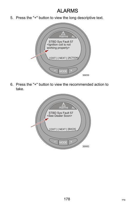
ALARMS
178 eng
5. Press the "+" button to view the long descriptive text.
MODE36659
[ NEXT ]
Alarms
[ EXIT ]
AL
[ACTION]
STBD Sys Fault 57<Ignition coil is notworking properly>
!
6. Press the "+" button to view the recommended action totake.
MODE36660
[ NEXT ]
Alarms
[ EXIT ]
AL
[BACK]
STBD Sys Fault 57<See Dealer Soon>
!
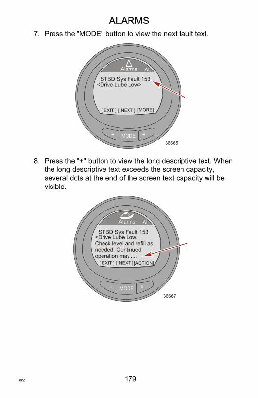
ALARMS
eng 179
7. Press the "MODE" button to view the next fault text.
MODE36665
[ NEXT ]
Alarms
[ EXIT ]
AL
[MORE]
STBD Sys Fault 153<Drive Lube Low>
!
8. Press the "+" button to view the long descriptive text. Whenthe long descriptive text exceeds the screen capacity,several dots at the end of the screen text capacity will bevisible.
MODE36667
[ NEXT ]
Alarms
[ EXIT ]
AL
[ACTION]
STBD Sys Fault 153<Drive Lube Low.Check level and refill asneeded. Continuedoperation may.....

ALARMS
180 eng
9. Press the "+" button to view the remaining long descriptivetext.
MODE36668
[ NEXT ]
Alarms
[ EXIT ]
AL
[ACTION]
STBD Sys Fault 153....may cause damage.>
10.Press the "+" button to view the recommended action totake.
MODE36669
[ NEXT ]
Alarms
[ EXIT ]
AL
[ BACK ]
STBD Sys Fault 153<Refer to Owner’smanual for serviceprocedure.>
11.Press the "+" button to return to the short descriptive textfault screen, or press the "MODE" button to view the nextalarm fault, or press the "–" button to exit the descriptive textscreen.
12.Press the "–" button to exit the "Alarms" menu and return tothe "Main Menu."

ALARMS
eng 181
EMISSION CONTROL ALARM WARNINGS WITHDESCRIPTIVE TEXTWhen a problem is detected with the emission control system, apop‑up window with the "AL" flashing in the upper right‑handcorner, an engine icon in the upper left‑hand corner, "OBDService Soon," and a large engine icon will be displayed on thescreen. The screen will flash between two alarm displays.Pressing the "–" button while this screen is displayed will exit tothe last screen that was on the monitor.
a - Engine iconb - Flashing "AL"c - OBD Service
Soon
MODE
Alarms AL
30259
[EXIT]
!
OBD Service Soona
b
c
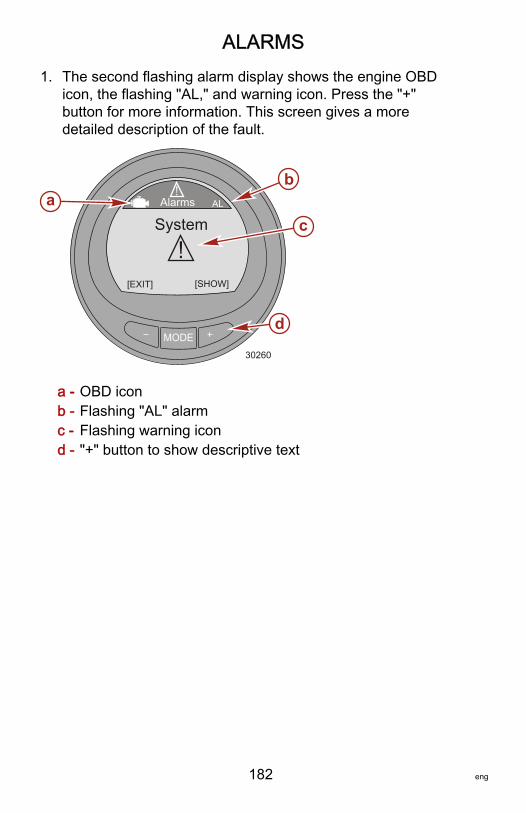
ALARMS
182 eng
1. The second flashing alarm display shows the engine OBDicon, the flashing "AL," and warning icon. Press the "+"button for more information. This screen gives a moredetailed description of the fault.
a - OBD iconb - Flashing "AL" alarmc - Flashing warning icond - "+" button to show descriptive text
MODE
Alarms AL
30260
![EXIT] [SHOW]
b
c
d
!
Systema

ALARMS
eng 183
2. The screen displays the engine location, the system faultcode number, and a description of the faulty component.Press the "+" button for more information. This screen givesa more detailed description of the fault.
a - Engine locationb - Fault codec - Fault description
3. A detailed description of the fault component is explained.Press the "+" button for information on a corrective action.
a - Detaileddescription ofthe faultcomponent
MODE
Alarms AL
30261
[EXIT] [MORE]
bc
!
STB Sys Fault 115a<Engine Sensor>
MODE
Alarms AL
30262
[EXIT] [ACTION]
!
STB Sys Fault 115a <Exhaust Oxygen
Sensor is not workingproperly>
b

OWNERS ASSISTANCE
184 eng
Local Repair ServiceAlways return your outboard to your local authorized dealershould the need for service arise. Only he has the factory trainedmechanics, knowledge, special tools, equipment, and genuineparts and accessories to properly service your engine should theneed occur. He knows your engine best.
Service Away from HomeIf you are away from your local dealer and the need arises forservice, contact the nearest authorized dealer. Refer to theYellow Pages of the telephone directory. If, for any reason, youcannot obtain service, contact the nearest Mercury MarineService Office.
Parts and Accessories InquiriesAll inquiries concerning genuine replacement parts andaccessories should be directed to your local authorized dealer.The dealer has the necessary information to order parts andaccessories for you. When inquiring on parts and accessories,the dealer requires the model and serial number to order thecorrect parts.
Service AssistanceYour satisfaction with your outboard product is very important toyour dealer and to us. If you ever have a problem, question orconcern about your outboard product, contact your dealer or anyauthorized Mercury Marine dealership. If additional assistance isrequired, take these steps.1. Talk with the dealership's sales manager or service
manager. If this has already been done, then contact theowner of the dealership.
2. Should you have a question, concern, or problem thatcannot be resolved by your dealership, please contactMercury Marine Service Office for assistance. MercuryMarine will work with you and your dealership to resolve allproblems.
The following information will be needed by the service office:

OWNERS ASSISTANCE
eng 185
• Your name and address• Daytime telephone number• Model and serial number of your outboard• The name and address of your dealership• Nature of problem
Mercury Marine Service OfficesFor assistance, call, fax, or write. Please include your daytimetelephone number with mail and fax correspondence.
United States, Canada
Telephone English ‑ (920) 929‑5040Français ‑ (905) 636‑4751
Mercury MarineW6250 W. Pioneer RoadP.O. Box 1939Fond du Lac, WI 54936-1939Fax English ‑ (920) 929‑5893
Français ‑ (905) 636‑1704
Website www.mercurymarine.com
Australia, Pacific
Telephone (61) (3) 9791‑5822 Brunswick Asia Pacific Group41–71 Bessemer DriveDandenong South, Victoria 3175Australia
Fax (61) (3) 9706‑7228
Europe, Middle East, Africa
Telephone (32) (87) 32 • 32 • 11 Brunswick Marine EuropeParc Industriel de Petit-RechainB-4800 Verviers,Belgium
Fax (32) (87) 31 • 19 • 65
Mexico, Central America, South America, Caribbean
Telephone (954) 744‑3500 Mercury Marine11650 Interchange Circle NorthMiramar, FL 33025U.S.A.
Fax (954) 744‑3535
Japan
Telephone 072‑233‑8888 Kisaka Co., Ltd.4-130 Kannabecho Sakai-shi Sakai-ku5900984 Osaka,Japan
Fax 072‑233‑8833
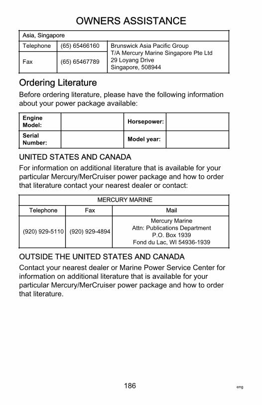
OWNERS ASSISTANCE
186 eng
Asia, Singapore
Telephone (65) 65466160 Brunswick Asia Pacific GroupT/A Mercury Marine Singapore Pte Ltd29 Loyang DriveSingapore, 508944
Fax (65) 65467789
Ordering LiteratureBefore ordering literature, please have the following informationabout your power package available:
EngineModel: Horsepower:
SerialNumber: Model year:
UNITED STATES AND CANADAFor information on additional literature that is available for yourparticular Mercury/MerCruiser power package and how to orderthat literature contact your nearest dealer or contact:
MERCURY MARINE
Telephone Fax Mail
(920) 929‑5110 (920) 929‑4894
Mercury MarineAttn: Publications Department
P.O. Box 1939Fond du Lac, WI 54936-1939
OUTSIDE THE UNITED STATES AND CANADAContact your nearest dealer or Marine Power Service Center forinformation on additional literature that is available for yourparticular Mercury/MerCruiser power package and how to orderthat literature.