menvier fire system mf9300 - bac security 9300 fire panel...menvier fire system mf9300 one, two and...
TRANSCRIPT
Menvier Fire System
MF9300
One, two and four zone control panels
Installation and User Instructions and Systems Log
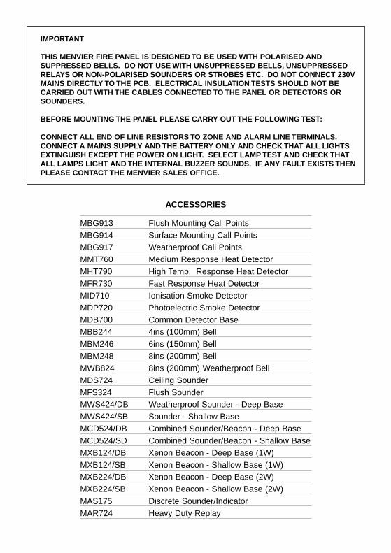
IMPORTANT
THIS MENVIER FIRE PANEL IS DESIGNED TO BE USED WITH POLARISED AND SUPPRESSED BELLS. DO NOT USE WITH UNSUPPRESSED BELLS, UNSUPPRESSED RELAYS OR NON-POLARISED SOUNDERS OR STROBES ETC. DO NOT CONNECT 230V MAINS DIRECTLY TO THE PCB. ELECTRICAL INSULATION TESTS SHOULD NOT BE CARRIED OUT WITH THE CABLES CONNECTED TO THE PANEL OR DETECTORS OR SOUNDERS.
BEFORE MOUNTING THE PANEL PLEASE CARRY OUT THE FOLLOWING TEST:
CONNECT ALL END OF LINE RESISTORS TO ZONE AND ALARM LINE TERMINALS.CONNECT A MAINS SUPPLY AND THE BATTERY ONLY AND CHECK THAT ALL LIGHTS EXTINGUISH EXCEPT THE POWER ON LIGHT. SELECT LAMP TEST AND CHECK THATALL LAMPS LIGHT AND THE INTERNAL BUZZER SOUNDS. IF ANY FAULT EXISTS THEN PLEASE CONTACT THE MENVIER SALES OFFICE.
ACCESSORIES
MBG913 Flush Mounting Call PointsMBG914 Surface Mounting Call PointsMBG917 Weatherproof Call PointsMMT760 Medium Response Heat DetectorMHT790 High Temp. Response Heat DetectorMFR730 Fast Response Heat DetectorMID710 Ionisation Smoke DetectorMDP720 Photoelectric Smoke DetectorMDB700 Common Detector BaseMBB244 4ins (100mm) BellMBM246 6ins (150mm) BellMBM248 8ins (200mm) BellMWB824 8ins (200mm) Weatherproof BellMDS724 Ceiling SounderMFS324 Flush SounderMWS424/DB Weatherproof Sounder - Deep BaseMWS424/SB Sounder - Shallow BaseMCD524/DB Combined Sounder/Beacon - Deep BaseMCD524/SD Combined Sounder/Beacon - Shallow BaseMXB124/DB Xenon Beacon - Deep Base (1W)MXB124/SB Xenon Beacon - Shallow Base (1W)MXB224/DB Xenon Beacon - Deep Base (2W)MXB224/SB Xenon Beacon - Shallow Base (2W)MAS175 Discrete Sounder/IndicatorMAR724 Heavy Duty Replay
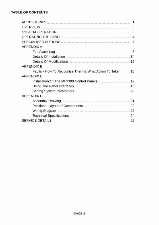
TABLE OF CONTENTS
ACCESSORIES 1OVERVIEW 3SYSTEM OPERATION 3OPERATING THE PANEL 4SPECIALISED OPTIONS 7APPENDIX A
Fire Alarm Log 8Details Of Installation 14Details Of Modifications 15
APPENDIX BFaults - How To Recognise Them & What Action To Take 16
APPENDIX CInstallation Of The MF9300 Control Panels 17Using The Panel Interfaces 18Setting System Parameters 20
APPENDIX DAssembly Drawing 21Positional Layout of Components 22Wiring Diagram 23Technical Specifications 24
SERVICE DETAILS 25
PAGE 2

OVERVIEWThis document gives details of how to install, test, use and maintain operation of your MF9300 firealarm panel.
SYSTEM OPERATION
What To Do At A Glance
The following information tells you what the various indicators, visible on the front panel, mean andhow you should react to them.
INDICATOR STATUS ACTION
GENERAL FIRE ON Fire detected alarms not sounded.
FLASHING Fire detected alarms sounded.
ALARM LINE DELAY ON No action. Alarm line delays are set up.
FLASHING Fire has been detected. Alarm delay is in action, check for fire.
SYSTEM FAULT ON Refer to service provider (see front ofthis manual for telephone number)
DISABLEMENT FLASHING No action. Zone(s) disabled.
TEST FLASHING Zone in test. If service provider is on site take no action. Else refer to service provider (see front of this manual for telephone number).
REMOTE SIGNAL ISOLATE ON No action. Remote signal output is isolated.
SUPERVISOR MODE ON No action - you are in Supervisor mode - see section on `Operating The Panel`.
FLASHING No action. System is self-checking. Indicator should go out within 25 seconds.
GENERAL FAULT FLASHING Refer to Appendix B
PAGE 3

OPERATING THE PANEL
General
The panel operates in 1 of 2 modes - Normal mode of Supervisor mode. In Normal mode theSupervisor mode LED is extinguished. In Supervisor mode the Supervisor LED is continuously ON.
Control of the facilities at the panel is available via the keyboard. A key press is acknowledged by ablip of the internal panel buzzer. All keys that are active in the Normal mode have their legendactually on the key itself, whereas all those facilities that are active once in the Supervisor mode havetheir legends above the corresponding key. For example, in Normal mode pressing the SILENCEBUZZER key will silence the internal panel buzzer. However, if in the Supervisor mode pressing thesame key will perform a Lamp Test.
Normal Mode
This is the condition the panel is generally to be found in. From the Normal mode the user may:
Silence Buzzer:
The user can silence the panel buzzer by pressing the SILENCE BUZZER button on the keyboard. The buzzer will then only sound approximately once every 10 seconds. NOTE that this does not silence any alarms, only the buzzer within the panel.
Entering the Supervisor mode:
By entering a 4 digit access code the user may get into the Supervisor mode. The access code for this panel is 2214. By pressing the numbered keys in the correct order, and then by hitting the ENTER key, the user will see the Supervisor mode indicator come on. Note that the buzzer will sound when it has recognised each key press. You are then in the Supervisor mode and may carry out additional facilities at the panel (see below).
Supervisor Mode
When in this mode a number of extra features are available to the user.
Silence/Resound Alarms:
When in the Supervisor mode this key can be used to either turn the alarms on or to silence them. It is a toggle action. So for example, to initiate an evacuation of a site you could press the Silence/resound alarm button to cause the alarms to sound. You could then silence the alarm at a later time by pressing the same button again. Note that if the alarms are silenced but there is still a Fire condition then the internal panel buzzer will buzz every 10 seconds. Also, if the alarms are silenced then this will not prevent subsequent new fire conditions from automatically resounding the alarms.
PAGE 4

Reset:
This facility allows you to reset the panel. When hit, all panel indicators will light and the internal panel buzzer will sound. On the MF9304 the Fault relay output will also activate. On releasing the button the lights will extinguish, the buzzer will silence and the relay output will deactivate. For a period of approximately 25 seconds after pressing the Reset button the Supervisor mode indicator will flash. This is indicating that the panel is 'self testing'. Once the panel is ready the Supervisor mode indicator will extinguish and you can continue using the panel as you like.
Disable/Enable:
The panel allows a supervisor to disable individual zones and/or the alarm lines. A zonewhichhas been disabled will not be monitored for faults or for fires. Similarly, If the alarm lines are put into disablement then they will not be monitored for faults, nor would they be activated in a fire condition on a zone. (Note that either both alarm lines are disabled at the same time or neither are disabled).
To actually disable zone/alarm lines you have to be in the Supervisor mode. Once there, press the Right Arrow key and a flashing 'cursor' will appear in the Alarm Line indicators. By repeatedly pressing the Right Arrow key you can step this 'cursor' through the Alarm Line indicators, onto the Zone Fault indicators. Keep pressing the same key and you will step through the zones, one at a time, until eventually it returns to the Alarm line indicators, and soon. When the indicator is at the zone or alarm lines that you wish to disable/re-enable then bysimply pressing the Disable/Enable button in zone/alarm lines will be toggled accordingly. TheDisablement indicator will flash, the internal buzzer will sound every 10 seconds and the corresponding Fault indicator(s) will light continuously for any zone or alarm line that is disabled. You may then use the Right Arrow key to move on and disable/re-enable further zones/alarm lines as required.
Note that a disablement is not cancelled by a reset or a removal of power to the panel.
Test:
The fire panel will allow the supervisor to put any zone into a test mode. To do this go into theSupervisor mode. Then press the Right Arrow key once and a flashing 'cursor' will appear in the Alarm indicators. Continue pressing the Right Arrow key until the 'cursor' reaches the zone that you want to put into test. Then press the Test button. The Test indicator will begin toflash, the internal panel buzzer will buzz at 10 second intervals and the Fault indicator of the zone concerned will light continuously. That particular zone is now in the Test mode.
When in test mode a detector/manual call point can be put into fire on that particular zone. The panel will recognise the fire condition and sound the alarms for 2 seconds. Then the panel will automatically reset the zone, in order to try and clear the fire condition. If the zone resets successfully then the alarms will sound again for 2 seconds. You can then go on and test the next detector/manual call point on the zone. If the zone fails to reset successfully, maybe due to a faulty detector or such like, then the panel will keep on trying to reset the zone for 2 minutes. If it has still failed at the end of this period then that zone immediately goes into fire.
Note that the alarm lines cannot be put into the test condition.
PAGE 5

The fact that a zone is in test will not prevent the panel from recognising and acting upon fires or faults in other zones.
To take a zone out of the test mode you must go into the Supervisor mode and then press Reset.
Remote Signal Isolate:
This feature is only available on MF9304 panels. To isolate the Remote Signal output press the Remote Signal Isolate button, whilst in Supervisor mode. The Remote Signal Isolate indicator will light, the Disablement indicator will flash and the internal panel buzzer will buzz every 10 seconds. To re-enable the Remote signal again at a later time simply press the Remote Signal Isolate button again. The corresponding indicators will extinguish and the panel buzzer will silence itself. Note that the remote signal isolate facility is not cancelled by a system reset.
Lamp Test Facility:
It is possible to test the indicators and the internal panel buzzer manually. To do this from within the Supervisor mode the Lamp Test button should be pressed. For the period that the button is kept depressed all panel indicators should light and the internal buzzer should sound. Once the button is released the panel will return to the condition it was in prior to the lamp test.
Exiting from the Supervisor Mode:
This mode will automatically exit if no key press is detected for a period of greater than 15 seconds. Alternatively, if you have finished in the Supervisor mode you may simply press ENTER. In either case the Supervisor mode indicator will extinguish and the panel will be back in the Normal mode.
PAGE 6
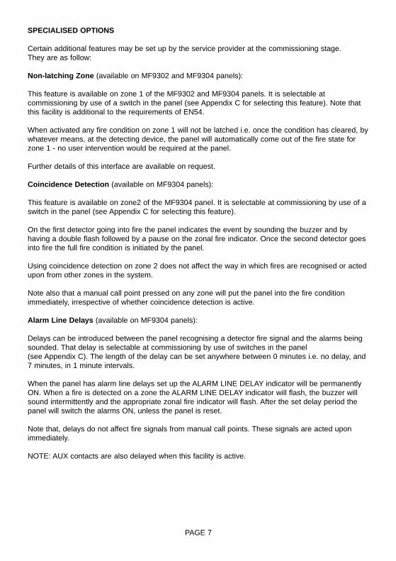
SPECIALISED OPTIONS
Certain additional features may be set up by the service provider at the commissioning stage.They are as follow:
Non-latching Zone (available on MF9302 and MF9304 panels):
This feature is available on zone 1 of the MF9302 and MF9304 panels. It is selectable atcommissioning by use of a switch in the panel (see Appendix C for selecting this feature). Note thatthis facility is additional to the requirements of EN54.
When activated any fire condition on zone 1 will not be latched i.e. once the condition has cleared, bywhatever means, at the detecting device, the panel will automatically come out of the fire state forzone 1 - no user intervention would be required at the panel.
Further details of this interface are available on request.
Coincidence Detection (available on MF9304 panels):
This feature is available on zone2 of the MF9304 panel. It is selectable at commissioning by use of aswitch in the panel (see Appendix C for selecting this feature).
On the first detector going into fire the panel indicates the event by sounding the buzzer and byhaving a double flash followed by a pause on the zonal fire indicator. Once the second detector goesinto fire the full fire condition is initiated by the panel.
Using coincidence detection on zone 2 does not affect the way in which fires are recognised or actedupon from other zones in the system.
Note also that a manual call point pressed on any zone will put the panel into the fire conditionimmediately, irrespective of whether coincidence detection is active.
Alarm Line Delays (available on MF9304 panels):
Delays can be introduced between the panel recognising a detector fire signal and the alarms beingsounded. That delay is selectable at commissioning by use of switches in the panel (see Appendix C). The length of the delay can be set anywhere between 0 minutes i.e. no delay, and7 minutes, in 1 minute intervals.
When the panel has alarm line delays set up the ALARM LINE DELAY indicator will be permanentlyON. When a fire is detected on a zone the ALARM LINE DELAY indicator will flash, the buzzer willsound intermittently and the appropriate zonal fire indicator will flash. After the set delay period thepanel will switch the alarms ON, unless the panel is reset.
Note that, delays do not affect fire signals from manual call points. These signals are acted uponimmediately.
NOTE: AUX contacts are also delayed when this facility is active.
PAGE 7

PAGE 8
Dat
eZ
one
Eve
ntA
ctio
n re
quire
dS
igne
d
FIR
EA
LA
RM
SY
ST
EM
LO
G -
PH
OTO
CO
PY
TH
ISS
HE
ET
AP
PE
ND
IXA
It is
rec
omm
ende
d th
at t
his
book
is m
aint
aine
d by
a r
espo
nsib
le e
xecu
tive
and
that
eve
ry ‘e
vent
’affe
ctin
g th
e in
stal
latio
n sh
ould
be
reco
rded
.A
n ‘e
vent
’sho
uld
incl
ude
fals
e al
arm
s, f
ailu
res,
tes
ts,
tem
pora
ry d
isco
nnec
tions
, th
e da
tes
of in
stal
ling
engi
neer
’s v
isits
and
a n
ote
of a
nyou
tsta
ndin
g w
ork
or c
ondi
tions
.

PAGE 9
Dat
eZ
one
Eve
ntA
ctio
n re
quire
dS
igne
d

PAGE 10
Dat
eZ
one
Eve
ntA
ctio
n re
quire
dS
igne
d

PAGE 11
Dat
eZ
one
Eve
ntA
ctio
n re
quire
dS
igne
d

PAGE 12
Dat
eZ
one
Eve
ntA
ctio
n re
quire
dS
igne
d

PAGE 13
Dat
eZ
one
Eve
ntA
ctio
n re
quire
dS
igne
d

DETAILS OF INSTALLATION
PAGE 14
Zone No.No. of Call
PointsNo. of Smoke
DetectorsNo. of HeatDetectors
Location
1
2
3
4
TOTAL
CURRENT
No. OF SOUNDER BELLS
ELECTRONIC
OTHER
TOTAL ALARM LOAD:
OTHER DETAILS OF EQUIPMENT:
THIS SYSTEM HAS BEEN INSTALLED IN ACCORDANCE WITH THE REQUIREMENTS OF EN54
SIGNED DATE
FOR
THIS SYSTEM HAS BEEN COMMISSIONED IN ACCORDANCE WITH THE REQUIREMENTS OF
EN54
SIGNED DATE
FOR

DETAILS OF MODIFICATIONS/ADDITIONS TO SYSTEM
DETAILS DATE
NOTES
OTHER REFERENCE DRAWING/PLANS TO BE USED WITH THIS LOG
PAGE 15
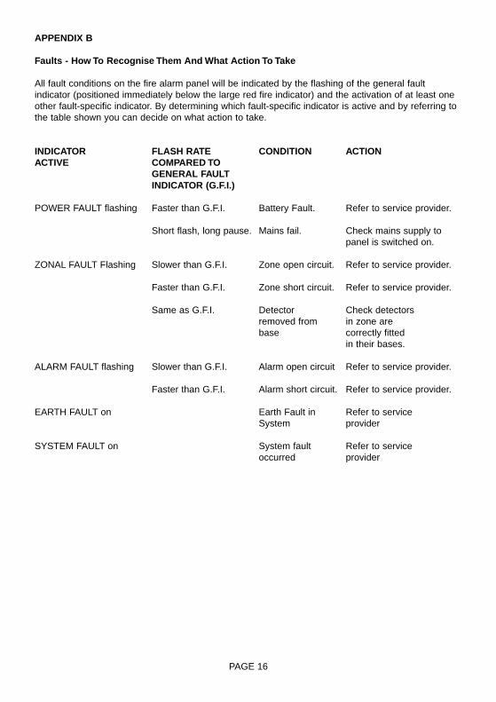
APPENDIX B
Faults - How To Recognise Them And What Action To Take
All fault conditions on the fire alarm panel will be indicated by the flashing of the general faultindicator (positioned immediately below the large red fire indicator) and the activation of at least oneother fault-specific indicator. By determining which fault-specific indicator is active and by referring tothe table shown you can decide on what action to take.
INDICATOR FLASH RATE CONDITION ACTIONACTIVE COMPARED TO
GENERAL FAULTINDICATOR (G.F.I.)
POWER FAULT flashing Faster than G.F.I. Battery Fault. Refer to service provider.
Short flash, long pause. Mains fail. Check mains supply to panel is switched on.
ZONAL FAULT Flashing Slower than G.F.I. Zone open circuit. Refer to service provider.
Faster than G.F.I. Zone short circuit. Refer to service provider.
Same as G.F.I. Detector Check detectorsremoved from in zone arebase correctly fitted
in their bases.
ALARM FAULT flashing Slower than G.F.I. Alarm open circuit Refer to service provider.
Faster than G.F.I. Alarm short circuit. Refer to service provider.
EARTH FAULT on Earth Fault in Refer to serviceSystem provider
SYSTEM FAULT on System fault Refer to serviceoccurred provider
PAGE 16

APPENDIX C
Installation Of The MF9300 Control Panels
General Points:
Before actually installing your MF9300 panel please note the following points about the system:
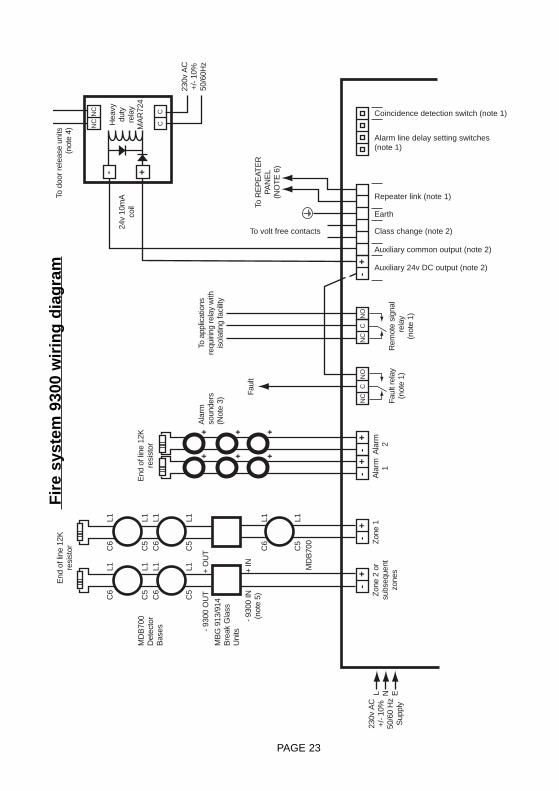
The wiring for each of the zones and alarm lines is to be a 2 core parallel circuit with the end of lineresistor fitted to the end of the circuit. No 'spurs' or 'tee offs' are permitted. The wiring diagram (Fig.3)gives more details.
If a zone is not to be used at all then the end of line resistor must be left in the relevant zone terminalblocks in the panel.
All equipment sued must be of the open circuit type.
Manual call points used in the system (MBG913/MBG914) are polarised. Use the connection detailsaccompanying the manual call points in order to ensure that the correct polarity of connections isobserved at all times. Also, make sure that the 'MF9300' terminals are used on the manual callpoints.
All cables should be tested for Earth fault before connection to the panel. Do not use a MEGGER onany cable after connection to any equipment including the fire panel.
The maximum load permitted on each of the 2 alarm sounder circuits is specified in the TechnicalSpecification (Appendix D, fig.4). The load should be spread equally across the circuits. All soundersmust be polarised, with the correct polarity of connections being observed at all times. Refer to thewiring diagram (Appendix D, fig.3) and the instructions with the relevant sounders for the appropriateconnection details.
All cables entering or leaving the panels must do so via the 'knock-out' positions provided.
Installing The Panel:
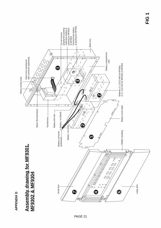
Follow the steps shown here in conjunction with the assembly diagram shown on the following pageof this manual (Fig.1):
1. Remove the unassembled panel components from the packaging (do not however, remove thecentral section from its plastic bag just yet).
Take the moulded back box and remove/drill any knockouts that are to be used, either on the top orrear of the enclosure. Note that specific knockout positions should be used for the AC mainssupply. These positions are indicated both on the back box itself and on the assembly diagram(Fig.1). Note also that cables should only enter or leave the enclosure via positions indicatedby the knockouts. Do not drill additional holes in the enclosure.
Fix the moulded back box to the wall. Use the 3 fixing holes in the back of the enclosure if it is to bemounted proud of the wall. Alternatively, for flush fixing, use the 5mm mounting holes (6 off) aroundthe lip of the rear enclosure to mount the panel.
2. Connect the batteries together using the battery connectors contained in the accessories bag -note the polarity of the connections on the assembly diagram (Fig.1). Fit the batteries into the batterycompartment of the rear enclosure.
PAGE 17

3. Using the packing piece(s) provided ensure that the batteries cannot move within the batterycompartment. For the MF9301 panel 3 packing pieces are used - their positions and orientations areshown in Fig.1. For the MF9302 and MF9304 panels only a single packing piece is used - again, seeFig.1 for details.
4. Ensure that all external wiring that is to be used is available within the back box. Wire the ACmains input to the mains terminal block within the rear enclosure. Check that the low voltage ACsupply is available at the mains connector. Remove the central section from its plastic bag. Connectthe battery connector to the PCB (ensure that the clip on the connector socket fits with the catch onthe connector plug on the PCB). A small spark may be seen at the connector when this is done - thisis quite normal. The internal buzzer should sound and the green POWER LED should flash (otherLEDs may also be lit - this too is quite normal at this stage). Connect the low voltage mainsconnector to the PCB (ensure that the clip on the connector socket fits with the catch on theconnector plug on the PCB). If all is well the green POWER LED should now be permanently ON.Fix the central section to the rear enclosure using the 3mm screws provided (4 off). Complete thewiring of the external circuits to the PCB terminal blocks as appropriate. Note that 1 of 2 Earth leads,hanging from the right hand end of the metal conduit entry plate, has no connector on the end of it.This wire MUST be wired up to the Earth terminal block. The other lead should pass down into thebattery compartment in order to be fixed to the battery cover plate.
5. Connect the remaining Earth strap, coming down from the metal conduit entry plate, to the batterycover plate. Fix the battery cover plate to the rear enclosure using the 3mm screws provided (6 off).
6. Fit the lower door.
7. Carry out the testing of the system. NOTE that all manual call points (MBG913/MBG914) used inthe system must be individually tested for correct operation. Then when satisfied that all is workingcorrectly fit the upper door - ensure that the door clicks into place and locks there.
WARNING: Operating up of a panel after installation should only be carried out by a suitablyqualified/trained person. Live parts are exposed by this operation so ensure that the mains supply isswitched off before attempting to service any of the parts inside the panel.
Routine testing of the system should be carried out as recommended in BS5839 part 1: 1988 (Clause29).
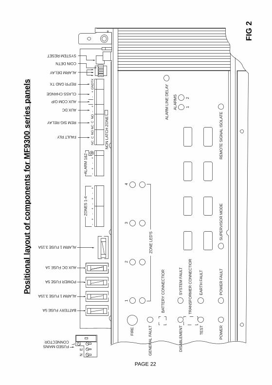
Using The Panel Interfaces:
The panels provide the following interfaces options. Fig.2 shows the location of the interface terminalblocks on the circuit board. Note that these features are in addition to the requirements of EN54.
Auxiliary DC Output(applicable to MF9302 and MF9304 panels)
A 24 VDC output is provided. This output may be switched via the auxiliary relays or used to driveexternal relays via the auxiliary zone/common outputs. This output is fused to protect against wiringfaults but is UNMONITORED by the panel i.e. if this fuse ruptures the panel will not register a fault.
PAGE 18

Class Change(applicable to MF9302 and MF9304 panels)
A pair of contacts are provided for a class change facility. By short circuiting these contacts via aswitch, pulse unit, time clock or by other means, the alarms will sound without illuminating the firelights. The alarms will cancel when the short circuit is removed. No voltage should be applied tothese terminals.
Auxiliary Common Output(applicable to MF9302 and MF9304 panels)
This is a 'solid state' semiconductor switch which operates on the activation of a fire on any latchingzone by 'pulling down' this output to 'zero volts' (Note, the activation does not occur for fires onnon-latching zones). This makes the output suitable for driving an external 24V relay with a coilcurrent of 10mA, maximum, which can be used for operating door release units etc. This output is notactivated by Sound Alarms or Class Change.
Auxiliary Fault Relay(applicable to MF9304 panels)
A 1 Amp (max), 24 VDC (resistive) voltage free single pole changeover relay is provided. The relaywill operate on the activation of any fault registered by the panel. 240V MUST NOT BE SWITCHEDWITH THIS RELAY.
Remote Signal RelayA 1 Amp (max), 24VDC (resistive) voltage free single pole changeover relay isprovided, operating onthe activation of any zone, after any delays are taken into account on that zone. The relay is forsignalling to a remote location, of for operation of an autodialler. Where it is required to signal to acontrol station an interface unit, supplied by the control station operator, will be required. This relay isnot activated during Sound Alarms, nor during Class Change. 240V MUST NOT BE SWITCHEDWITH THIS RELAY.
An isolate facility is provided to enable the panel to be tested without operating the remote signalrelay. This facility is available in the supervisor mode from the front panel. When pushed the RemoteSignal Isolate LED will light and the internal buzzer will sound every 10 seconds. Note that doing asystem Reset will not cancel the isolate facility.
Repeater Output(applicable to MF9304 panels)
A 2 wire serial link interface is provided for connecting to a repeater panel. Further details of thisinterface are available on request.
Do not exceed the maximum output current rating stated in the Technical Specification(Appendix D)
PAGE 19

Setting System Parameters
Certain facilities that can be set up by the service provider at commissioning. They are as follows:
Non-latching Zone (available on MF9302 and MF9304):
To enable this facility gain access to the service area of the panel and push the Non-latching zoneswitch down (Fig.2). Then press the SYSTEM RESET switch. The panel will reset and the non-latching zone feature will be available on zone 1.
Coincidence Detection (available on MF9304):
To enable this facility gain access to the service area of the panel. On the bit-switch (see Fig.2)move switch 4 to the ON position. Then press the SYSTEM RESET button. The panel will reset andthe coincidence detection feature will then be available for use on zone 2.
Alarm Line Delays (available on MF9304):
Again, to enable alarm line delays gain access to the service area. The delay period is set byadjusting the positions of the bit switches (see Fig.2) as follows:
SWITCH POSITION1 2 3
DELAY(MINS)
0 OFF OFF OFF1 ON OFF OFF2 OFF ON OFF3 ON OFF ON4 OFF OFF ON5 ON OFF ON6 OFF ON ON7 ON ON ON
After the delay period is selected press the SYSTEM RESET switch. The panel will reset, the ALARMLINE DELAY indicator will light and the delays will be used when appropriate.
PAGE 20
PAGE 21
Larg
e do
or
Mid
dle
mou
ldin
gB
atte
ry c
over
pla
te
Sm
all d
oor
" #$
%
&
&
'
(
Bac
k bo
x
Bat
tery
com
partm
ent
only
Do
not r
emov
epo
lyst
yren
e pa
ckin
gS
olid
line
s ba
ttery
&pa
ckin
g fo
r MF
9302
& M
F93
04D
ashe
d lin
es b
atte
ry
& p
acki
ng fo
r MF
9301
Bat
terie
s 2
x 12
V,3.
4Ah
for M
F93
01or
2 x
12V
,7A
h fo
r MF
9302
& M
F93
04
Mai
ns c
ondu
it en
try
Mai
ns T
erm
inal
blo
ck
Tran
sfor
mer
Bat
tery
-ve
(bla
ck)
Bat
tery
link
wire
Bat
tery
+ve
(red
)
Bat
tery
con
nect
or(p
olar
ised
)
Wire
s fro
m tr
ansf
orm
erw
ith c
onne
ctor
(pol
aris
ed)
AP
PE
ND
IXD
Ass
emb
ly d
raw
ing
fo
r M
F93
01,
MF
9302
& M
F93
04
FIG
1
PAGE 22
BAT
TE
RY
CO
NN
EC
TIO
R
TR
AN
SF
OR
ME
R C
ON
NE
CT
IOR
SY
ST
EM
FA
ULT
FIR
E
NE
L
GE
NE
RA
L FA
ULT
DIS
AB
LEM
EN
T
TE
ST
PO
WE
RP
OW
ER
FA
ULT
SU
PE
RV
ISO
R M
OD
ER
EM
OT
E S
IGN
AL
ISO
LAT
E
ALA
RM
LIN
E D
ELA
Y
NO
N L
ATC
H Z
ON
E
ZO
NE
S 1
-4A
LAR
M 1
&2
NC
CN
ON
CC
NO
-+
-+
-+
-+
-+
-+
-+
-+
GN
DT
X
ALA
RM
S
12
EA
RT
H F
AU
LT
ZO
NE
LE
D'S
12
34
FAULT RLY
ALARM 1 FUSE 3.15A
AUX DC FUSE 1A
POWER FUSE 5A
BATTERY FUSE 5A
FUSED MAINSCONNECTOR
ALARM 1 FUSE 3.15A
REM SIG RELAY
AUX DC
AUX COM O/P
CLASS CHANGE
REP'R GND TX
ALARM DELAY
COIN DETN
SYSTEM RESET
Po
siti
on
al la
you
t o
f co
mp
on
ents
fo
r M
F93
00 s
erie
s p
anel
s
FIG
2
PAGE 23
Ala
rm 1Z
one
1
End
of l
ine
12K
resi
stor
End
of l
ine
12K
resi
stor
Zon
e 2
orsu
bseq
uent
zone
s
230v
AC
+/- 1
0%50
/60
Hz
Sup
ply
L N E
Ala
rm 2Fa
ult r
elay
(not
e 1)
Rem
ote
sign
al r
elay
(not
e 1)
-+
-+
-+
-+
-+
NC
CN
O
NC
NC
CC
- +
Auxiliary 24v DC output (note 2)
Auxiliary common output (note 2)
Class change (note 2)To volt free contacts
Earth
Repeater link (note 1)
NC
CN
O
Coincidence detection switch (note 1)
Alarm line delay setting switches(note 1)
C6
C5
C6
C5
L1 L1 L1 L1
C6
C5
C6
C5
L1 L1 L1 L1
+ + +C
6
C5
MD
B70
0
+ O
UT
+ IN
- 930
0 O
UT
MB
G 9
13/9
14B
reak
Gla
ssU
nits
Ala
rmso
unde
rs(N
ote
3)
To a
pplic
atio
nsre
quiri
ng re
lay
with
isol
atin
g fa
cilit
y
To R
EP
EAT
ER
PAN
EL
(NO
TE
6)
230v
AC
+/- 1
0%50
/60H
z
Hea
vydu
tyre
lay
MA
R72
4
24v
10m
Aco
il
To d
oor r
elea
se u
nits
(not
e 4)
Faul
t
MD
B70
0D
etec
tor
Bas
es
- 930
0 IN
(not
e 5)
L1 L1
+ + +
Fir
e sy
stem
930
0 w
irin
g d
iag
ram

TECHNICAL SPECIFICATIONS
MF9301 MF9302 MF9304
No. of zones 1 2 4
No. of alarm circuits 2 2 2
Mains input voltage 230 VAC +/- 10% 50Hz
System operating voltage 24 VDC
MonitoringZonesAlarms
Open, short circuit and detector removedOpen, short circuit
End of line elementsZonesAlarms
12K resistor supplied with panel12K resistor supplied with panel
Maximum loadingsZones (per zone) Break glass units, heat detectors and smoke detectors
(Combined max - 32)
Alarm lines 300mA total 500mA/line (1A max)
User controls 8 key keypad providing Access level 1 and Access level 2control - entry to Access level 2 by 4 digit keycode
Fault indicationsPower Mains fail, battery disconnected, battery low/short circuit
Zone Open, short circuit and detector removed
Alarm Open/short circuit
Earth fault Earth fault in system
System fault Controller error, code/data/comms error etc
Fire indicators Large common fire LED plus individual zonal LED’s
Auxilliary DC output NOT FITTED 24V DC 100mA maximum (fused but unmonitored)
Auxilliary fault relay NOT FITTED1A 24VDC resistive
Single pole c/o contacts
Remote signal relay NOT FITTED1A 24VDC resistive
Singlepole c/o contacts- isolate facility available
Auxilliary common output NOT FITTED Active pull-down to 0V
Repeater drive capacity NOT FITTED1 repeater via
2 wire serial link
Class change facility NOT FITTED 1 pair terminals - short to sound alarms
Terminal conductor capacity 0.5mm sq. to 2.5mm sq. maximum
Integral charger (mA) 0.4 0.7 0.7
Battery capacity (AH) 3.4 7 7
Battery type2 x 12V Sealed Lead Acid (Supplied)
Recommended replacement period 4 years
Standby on mains failure 72 Hours backup operating in the normal mode followedby 1/2 hr in the fire condition
Recharge period 24 hours
Dimensions 393mm (W) x 344mm (H) x 95mm (D)
PAGE 24

NOTES
PAGE 25
Lighting and SecurityCooper Lighting and Security Ltd.Wheatley Hall Road, Doncaster, South Yorkshire, DN2 4NB, United Kingdom
Sales General Export
Tel: +44 (0)1302 - 303303 +44 (0)1302 - 321541 +44 (0)1302 - 303250 Fax: +44 (0)1302 - 367155 +44 (0)1302 - 303220 +44 (0)1302 - 303251Email: [email protected] [email protected] [email protected] PINST FA9300/V www.cooper-ls.com
For service Tel:please call:
Service agreement number