mem 341_chapter 9 hydraulic circuit
TRANSCRIPT

8/12/2019 MEM 341_Chapter 9 Hydraulic Circuit
http://slidepdf.com/reader/full/mem-341chapter-9-hydraulic-circuit 1/22
MEM341_Chapter 9_Hydraulic circuits
9.0 Industrial hydraulic circuit
In this chapter we will discuss basic hydraulic circuits that used the most basic
components that make up a hydraulic system.
Basic electrical control devices (push button switches, pressure switches, solenoids,relays, timers and basic electrical control devices (ladder diagram) will not be included.
A hydraulic circuit is a group of components such as pumps, actuators, control valves and
conductors (pipes) are arranged so that they will perform a certain task.
Three important factors when analyzing or designing hydraulic circuit:
o safety of operation
o performance of desired function
o efficiency of operation
Circuit drawing has to be done using standards that are recognized worldwide.
Standard are important for the following reasons:
o interchangeable of components
o Symbols and circuit diagrams can be read by everyone. So that the hydraulic
circuit can be interpreted and install correctly
The standards organizations in this field are:
o BS (British Standards)
o ANSI (American National Standards Institution)
o ISO (International Standards Organization)

8/12/2019 MEM 341_Chapter 9 Hydraulic Circuit
http://slidepdf.com/reader/full/mem-341chapter-9-hydraulic-circuit 2/22
MEM341_Chapter 9_Hydraulic circuits
Example of industrial hydraulic circuit

8/12/2019 MEM 341_Chapter 9 Hydraulic Circuit
http://slidepdf.com/reader/full/mem-341chapter-9-hydraulic-circuit 3/22
MEM341_Chapter 9_Hydraulic circuits
9.1 Graphic symbols
Symbols are used in all parts of the world for designating components in fluid power
circuits.
Example of symbols of in fluid power circuits
The intent of a graphic symbol is to represent the:
o Type
o Functions
o Operation
o External connections
o Does not show the actual construction of the unit
Fluid power graphic symbols consist of basic figures:
o Lines
o Circles
o Squares
o Triangles
o Dots
o Arrows

8/12/2019 MEM 341_Chapter 9 Hydraulic Circuit
http://slidepdf.com/reader/full/mem-341chapter-9-hydraulic-circuit 4/22
MEM341_Chapter 9_Hydraulic circuits
A number of mechanisms are used to control the valves in a fluid power system.
Control mechanisms are shown on the end of the general valve graphic symbol.
Example control mechanism symbols
Joining of lines in a circuit is represented by a graphic symbol, which is a dot.
Lines that cross without joining are shown as an arc crossing without a dot.

8/12/2019 MEM 341_Chapter 9 Hydraulic Circuit
http://slidepdf.com/reader/full/mem-341chapter-9-hydraulic-circuit 5/22
MEM341_Chapter 9_Hydraulic circuits
Symbols for pressure control valves are shown as normally open or normally closed
Normally open valve is open at rest, allowing flow through the valve
Normally closed valve is closed at rest, blocking flow through the valve
Symbols for normally open and normally closed pressure control valves
Simplified symbol for an adjustable flow control valve shows an orifice with an arrow
drawn diagonally across it.
Arrow indicates the orifice is adjustable
When appropriate, symbols also indicate pressure and temperature compensation
Symbol for an adjustable flow control valve
Symbols for pressure- and temperature-compensated flow control valves; symbols
may be combined
8/12/2019 MEM 341_Chapter 9 Hydraulic Circuit
http://slidepdf.com/reader/full/mem-341chapter-9-hydraulic-circuit 6/22

8/12/2019 MEM 341_Chapter 9 Hydraulic Circuit
http://slidepdf.com/reader/full/mem-341chapter-9-hydraulic-circuit 7/22
MEM341_Chapter 9_Hydraulic circuits
Circuit diagrams provide a variety of information about fluid power systems for use
during system assembly, operation, and testing.
o Schematic diagrams
o Component lists
o Sequence of operation
Circuit diagram schematics must:
o Include all components and connections
o Be logically arranged so it is possible to easily follow the operating cycle of the
system
For more hydraulic circuit symbols, refer to the appendix section at the end of the notes.

8/12/2019 MEM 341_Chapter 9 Hydraulic Circuit
http://slidepdf.com/reader/full/mem-341chapter-9-hydraulic-circuit 8/22
MEM341_Chapter 9_Hydraulic circuits
9.2 Basic circuit design and example of circuit applications
Hydraulic circuit involve a group of components that closely work together to produce a
desired performance
i.
Pressure control
ii. Flow control
iii. Motion control
iv. Miscellaneous functions
A hydraulic circuit typically includes several of these segments
Control of a single-acting hydraulic cylinder
Control of single-acting cylinder
Figure shows a two-position, three-way, manually actuated, spring-offset DCV usedto control the operation of a single-acting cylinder.
In the spring offset mode, full pump flow goes to the tank via the pressure reliefvalve.
The spring in the rod end of the cylinder retracts the piston as oil from the blank end
drains back to the tank. When the valve is manually actuated into its left position, pump flow extends the
cylinder.
At full extension, pump flow goes through the pressure relief valve.
Deactivation of the DCV allows the cylinder to retract as the DCV shifts into itsspring offset mode.

8/12/2019 MEM 341_Chapter 9 Hydraulic Circuit
http://slidepdf.com/reader/full/mem-341chapter-9-hydraulic-circuit 9/22
MEM341_Chapter 9_Hydraulic circuits
Control of a double-acting hydraulic cylinder
Control of a double-acting hydraulic cylinder
When the four-way valve is in its spring-centered position, the cylinder is
hydraulically locked. Also the pump is unloaded back to the tank at essentially
atmospheric pressure.
When the four-way valve is actuated into the flow path configuration of the left
position, the cylinder extends against its load force F load as oil flows from port P
through port A. Also, oil in the rod end of the cylinder is free to flow back to the tank
ia the four-way valve from port B through port T.
When the four-way valve is deactivated, the DCV returns to its center position, and
the cylinder is once again hydraulically locked.
When the four way valve is actuated into the right position configuration, the cylinder
retracts as oil flows from port P through port B. Oil in the blank end is returned to the
tank via the flow path from port A through port T.
At the end of the stroke, there is no system demand for oil. Thus pump flow goes
through the relief valve back to the tank.

8/12/2019 MEM 341_Chapter 9 Hydraulic Circuit
http://slidepdf.com/reader/full/mem-341chapter-9-hydraulic-circuit 10/22
MEM341_Chapter 9_Hydraulic circuits
Regenerative hydraulic circuit
o Used to speed up the extending speed of a double acting cylinder
o Unfortunately, load carrying capability of the cylinder during extension is reduced.
Operation:
The operation of the cylinder during the retraction stroke is the same as that of a
regular double-acting cylinder. Fluid flows through the DCV via the right position
during retraction.
When DCV is shifted into its left position, the cylinder extends. The speed of
extension is greater than that for a regular double-acting cylinder because flow form
the rod end regenerates with the pump flow higher total pump flow.
Basic regenerative hydraulic circuit
Application of regenerative hydraulic circuit, can be seen in Drilling Machine
Drilling machine application

8/12/2019 MEM 341_Chapter 9 Hydraulic Circuit
http://slidepdf.com/reader/full/mem-341chapter-9-hydraulic-circuit 11/22
MEM341_Chapter 9_Hydraulic circuits
In center position, cylinder extends rapidly.
In left position, cylinder extension speed reduces; this is when the drill starts to cut
into the workpiece.
The right envelope mode retracts the cylinder.
Why does the center position result is the cylinder to rapidly extend?
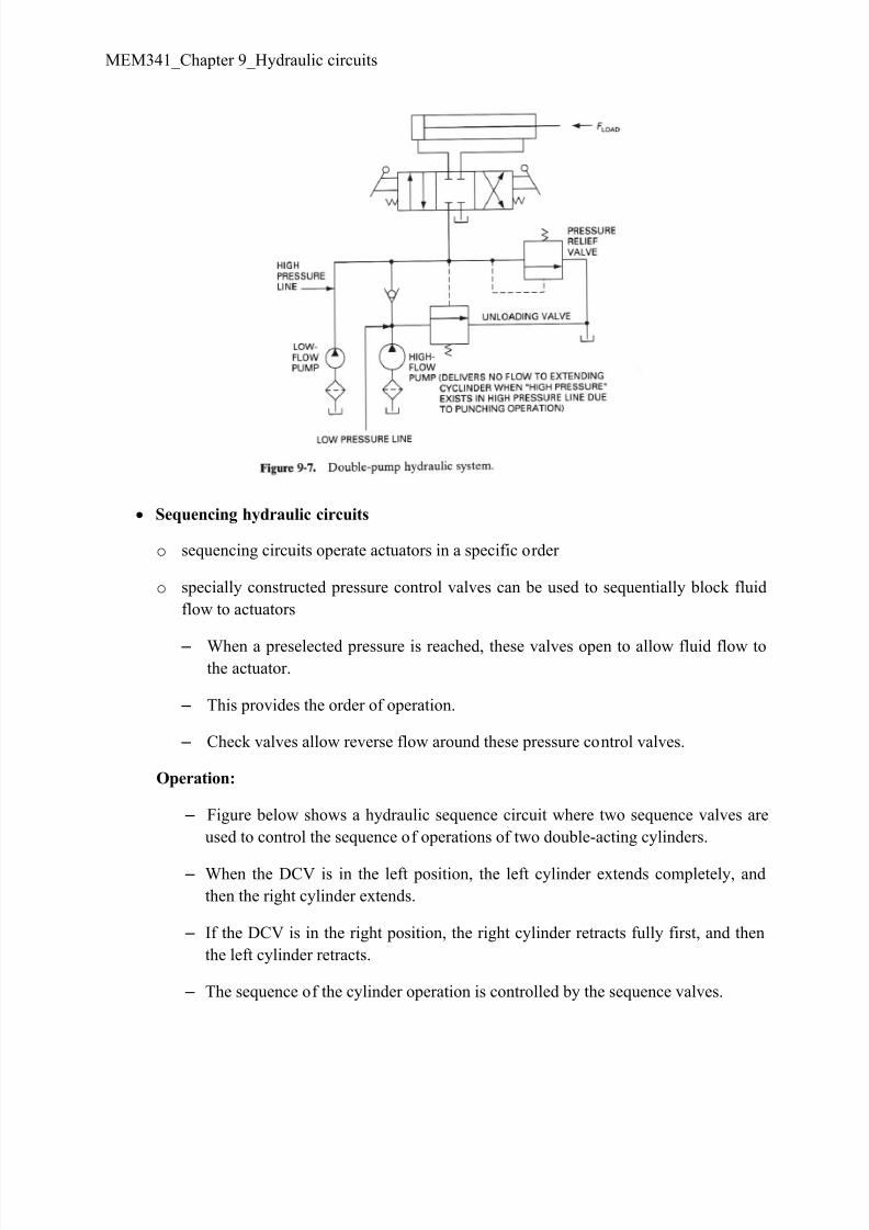
Double pump hydraulic circuit
- In a double pump hydraulic circuit, a high and low pump is used in tandem.
- Provides high-volume flow during low-pressure demand.
- Provides low-volume flow during high-pressure demand.
- Lowers equipment costs by reducing prime mover size and cuts ongoing system energy
consumption.
- Typical application is a sheet metal punch press in which the cylinder must extend
rapidly over great distance with very low pressure but high flow-rate requirements.
Operation of a sheet metal punch press
- In the left position, rapid extension occurs under no external load as the punching to
which is connected to the end of the cylinder approaches the sheet metal strip to be
punched.
- During the short motion portion when the punching operation occurs, the pressure
requirements are high due to the punching load. During the punching operation, the
cylinder travel is small and thus the flow-rate requirements are low.
- When the punching operation begins, the increased pressure opens the unloading valve
to unload the low-pressure pump. The purpose of the relief valve is to protect the high-
pressure pump from overpressure at the end of the cylinder stroke and when the DCV is
in its center position.
- The check valve protects the low-pressure pump from high pressure, which occurs
during the punching operation, at the ends of the cylinder stroke, and when the DCV is inits center position.
8/12/2019 MEM 341_Chapter 9 Hydraulic Circuit
http://slidepdf.com/reader/full/mem-341chapter-9-hydraulic-circuit 12/22
MEM341_Chapter 9_Hydraulic circuits
Sequencing hydraulic circuits
o sequencing circuits operate actuators in a specific order
o specially constructed pressure control valves can be used to sequentially block fluid
flow to actuators
– When a preselected pressure is reached, these valves open to allow fluid flow tothe actuator.
– This provides the order of operation.
– Check valves allow reverse flow around these pressure control valves.
Operation:
– Figure below shows a hydraulic sequence circuit where two sequence valves are
used to control the sequence of operations of two double-acting cylinders.
– When the DCV is in the left position, the left cylinder extends completely, and
then the right cylinder extends.
– If the DCV is in the right position, the right cylinder retracts fully first, and then
the left cylinder retracts.
– The sequence of the cylinder operation is controlled by the sequence valves.

8/12/2019 MEM 341_Chapter 9 Hydraulic Circuit
http://slidepdf.com/reader/full/mem-341chapter-9-hydraulic-circuit 13/22
MEM341_Chapter 9_Hydraulic circuits
– When in the center position of the DCV, both cylinders are locked in place.
– Example of application can be seen in production operation:
o Where the left cylinder could extend and clamp a workpiece via a power
vise jaw. Then the right cylinder extends to drive a spindle to drill a holein the workpiece.
o The right cylinder then retracts the drill spindle, and then the left cylinder
retracts to release the workpiece for removal.

8/12/2019 MEM 341_Chapter 9 Hydraulic Circuit
http://slidepdf.com/reader/full/mem-341chapter-9-hydraulic-circuit 14/22
MEM341_Chapter 9_Hydraulic circuits
Cylinder synchronizing hydraulic circuits
o Figure below shows two identical cylinders which is synchronized by piping them in
parallel.
o The loads on the cylinders must also be the same in order for them to extend in exactsynchronization. If the loads are not the same, the cylinder with the smaller load will
extend first because it will move at a lower pressure level.
o After this cylinder has fully completed its stroke, the system pressure will increase to
the higher level required to extend the cylinder with the greater load.
o However, in most cases, no two cylinders are really the same preventing cylinder
synchronization of the circuit.
o Therefore, to ensure cylinders movement is synchronize, the two cylinders must be
connected in series.
o The figure below shows that connecting two-cylinders in series is a simple way to
synchronize the two cylinders.
o During the extending stroke of the cylinders, fluid from pump is delivered to the
blank end of cylinder 1 via the flow path shown in the upper position of the DCV. As
cylinder 1 extends, fluid from its rod end is delivered to the blank end of cylinder 2.
o Fluid returns to the oil tank from the rod end of cylinder 2 as it extends, via the DCV.

8/12/2019 MEM 341_Chapter 9 Hydraulic Circuit
http://slidepdf.com/reader/full/mem-341chapter-9-hydraulic-circuit 15/22
MEM341_Chapter 9_Hydraulic circuits

8/12/2019 MEM 341_Chapter 9 Hydraulic Circuit
http://slidepdf.com/reader/full/mem-341chapter-9-hydraulic-circuit 16/22
MEM341_Chapter 9_Hydraulic circuits
Motor powered hydraulic circuits
Two factors that are basic to motor operation are:
i. Fluid flow rate establishes motor speed
ii. Pressure establishes torque output
o Figure below shows a circuit where speed control of a hydraulic motor is
accomplished using a pressure-compensated flow control valve.
The operation is as follow:
i. In center position, the motor is hydraulically locked.
ii. In left position, the motor rotates in one direction. Its speed can be varied
by adjusting the setting of the throttle of the flow control valve.
iii. When returned to the center position, the motor stops suddenly and
becomes locked.
iv. In right position, the motor turns in the opposite direction. The pressure
relief valve provides overload protection if, for example, the motor
experience an excessive torque.

8/12/2019 MEM 341_Chapter 9 Hydraulic Circuit
http://slidepdf.com/reader/full/mem-341chapter-9-hydraulic-circuit 17/22
MEM341_Chapter 9_Hydraulic circuits
Hydraulic motor braking system
o When using hydraulic motor in fluid power system, consideration should be
given to the type of loading that the motor will experience.
o A hydraulic motor may be driving a machine having large inertia (requireshigher work output to ensure motion).
o This would create a flywheel effect (continuous motion even after loading is
removed) resulting in build-up pressure at the pump when flow of fluid to the
motor is stopped.
o The figure below shows a hydraulic motor braking circuit which would stop
the motor rapidly but without damage to the system.

8/12/2019 MEM 341_Chapter 9 Hydraulic Circuit
http://slidepdf.com/reader/full/mem-341chapter-9-hydraulic-circuit 18/22
MEM341_Chapter 9_Hydraulic circuits

8/12/2019 MEM 341_Chapter 9 Hydraulic Circuit
http://slidepdf.com/reader/full/mem-341chapter-9-hydraulic-circuit 19/22
MEM341_Chapter 9_Hydraulic circuits

8/12/2019 MEM 341_Chapter 9 Hydraulic Circuit
http://slidepdf.com/reader/full/mem-341chapter-9-hydraulic-circuit 20/22
MEM341_Chapter 9_Hydraulic circuits

8/12/2019 MEM 341_Chapter 9 Hydraulic Circuit
http://slidepdf.com/reader/full/mem-341chapter-9-hydraulic-circuit 21/22
MEM341_Chapter 9_Hydraulic circuits

8/12/2019 MEM 341_Chapter 9 Hydraulic Circuit
http://slidepdf.com/reader/full/mem-341chapter-9-hydraulic-circuit 22/22
MEM341_Chapter 9_Hydraulic circuits
Tutorial Questions
1. When analyzing or designing a hydraulic circuit, what are three important considerations?
2. What is the purpose of a regenerative circuit?
3. List down, sketch and describe the operation of a single-acting hydraulic cylinder.
4. List down, sketch and describe the operation of a double-acting hydraulic cylinder.
5. Name one application of a regenerative cylinder circuit, list down, sketch, and describe its
operation.
6. List down, sketch and describe the operation of a sheet metal punch press machine.
7. List down, sketch and describe the operation of a hydraulic cylinder sequencing circuit.
8. List down, sketch and describe the operation for the hydraulic cylinder synchronizing circuits.
9. How is the speed of a hydraulic motor accomplished? List down, sketch, and describe the
circuit.
10. Describe the hydraulic motor breaking system.