melsec iq-f sample ladder reference for fx5 and power ... · energy measuring unit ecomonitorlight...
TRANSCRIPT
MELSEC iQ-F Sample Ladder Reference for FX5 and Power Distribution Measuring Instrument with RS-485 Communication (MODBUS RTU Protocol)(Overseas)


CO
NT
EN
TS
CONTENTS
CHAPTER 1 SAMPLE LADDER LIST 2
CHAPTER 2 SAMPLE LADDER 4
2.1 Data Read . . . . . . . . . . . . . . . . . . . . . . . . . . . . . . . . . . . . . . . . . . . . . . . . . . . . . . . . . . . . . . . . . . . . . . . . . . . . . . . 4
2.2 Data Write . . . . . . . . . . . . . . . . . . . . . . . . . . . . . . . . . . . . . . . . . . . . . . . . . . . . . . . . . . . . . . . . . . . . . . . . . . . . . . 32
REVISIONS. . . . . . . . . . . . . . . . . . . . . . . . . . . . . . . . . . . . . . . . . . . . . . . . . . . . . . . . . . . . . . . . . . . . . . . . . . . . . .46
TRADEMARKS . . . . . . . . . . . . . . . . . . . . . . . . . . . . . . . . . . . . . . . . . . . . . . . . . . . . . . . . . . . . . . . . . . . . . . . . . . .46
1
2
1 SAMPLE LADDER LIST
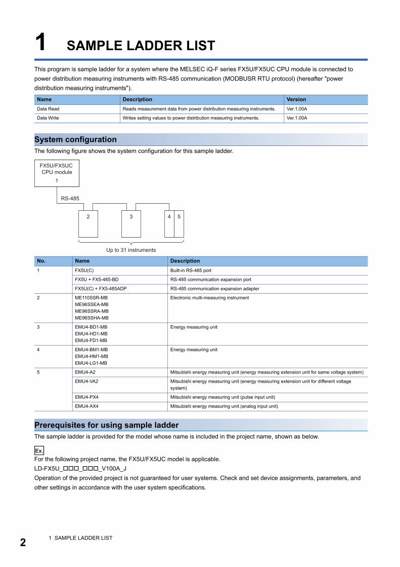
This program is sample ladder for a system where the MELSEC iQ-F series FX5U/FX5UC CPU module is connected to
power distribution measuring instruments with RS-485 communication (MODBUSR RTU protocol) (hereafter "power
distribution measuring instruments").
System configurationThe following figure shows the system configuration for this sample ladder.
Prerequisites for using sample ladderThe sample ladder is provided for the model whose name is included in the project name, shown as below.
Ex.
For the following project name, the FX5U/FX5UC model is applicable.
LD-FX5U___V100A_J
Operation of the provided project is not guaranteed for user systems. Check and set device assignments, parameters, and
other settings in accordance with the user system specifications.
Name Description Version
Data Read Reads measurement data from power distribution measuring instruments. Ver.1.00A
Data Write Writes setting values to power distribution measuring instruments. Ver.1.00A
No. Name Description
1 FX5U(C) Built-in RS-485 port
FX5U + FX5-485-BD RS-485 communication expansion port
FX5U(C) + FX5-485ADP RS-485 communication expansion adapter
2 ME110SSR-MB
ME96SSEA-MB
ME96SSRA-MB
ME96SSHA-MB
Electronic multi-measuring instrument
3 EMU4-BD1-MB
EMU4-HD1-MB
EMU4-FD1-MB
Energy measuring unit
4 EMU4-BM1-MB
EMU4-HM1-MB
EMU4-LG1-MB
Energy measuring unit
5 EMU4-A2 Mitsubishi energy measuring unit (energy measuring extension unit for same voltage system)
EMU4-VA2 Mitsubishi energy measuring unit (energy measuring extension unit for different voltage
system)
EMU4-PX4 Mitsubishi energy measuring unit (pulse input unit)
EMU4-AX4 Mitsubishi energy measuring unit (analog input unit)
RS-485
2
1
3
Up to 31 instruments
4 5
FX5U/FX5UC CPU module
1 SAMPLE LADDER LIST

1
Wiring and communication settingThis program requires wiring and communication settings, such as setting station numbers of a CPU module and powerdistribution measuring instruments and transmission speed, before communications. For the details on the wiring and
communication setting methods, refer to the operating manual of each power distribution measuring instrument, and for the
CPU module to the MELSEC iQ-F FX5 User's Manual (MODBUS Communication).
Related manuals MELSEC iQ-F FX5 Programming Manual (Instructions, Standard Functions/Function Blocks)
MELSEC iQ-F FX5 User's Manual (Application)
MELSEC iQ-F FX5 User's Manual (MODBUS Communication)
Electronic Multi-Measuring Instrument User's Manual: Detailed Edition (ME110SSR-MB Series)
Electronic Multi-Measuring Instrument User's Manual: Detailed Edition (ME110SSR-MB Series) (Three phase 4-wire)
Electronic Multi-Measuring Instrument MODBUS Interface specifications (ME110SSR-MB Series)
Electronic Multi-Measuring Instrument User's Manual: Detailed Edition (ME96SSEA-MB Series)
Electronic Multi-Measuring Instrument User's Manual: Detailed Edition (ME96SSRA-MB Series)
Electronic Multi-Measuring Instrument User's Manual: Detailed Edition (ME96SSHA-MB Series)
Electronic Multi-Measuring Instrument MODBUS Interface specifications (ME96SSEA-MB, ME96SSRA-MB,
ME96SSHA-MB Series)
Energy Measuring Unit User's Manual (Details) (EMU4-BD1-MB, EMU4-HD1-MB)
Energy Measuring Unit User's Manual (Details) (EMU4-BM1-MB, EMU4-HM1-MB)
Energy Measuring Unit User's Manual (Details) (EMU4-LG1-MB)
Energy Measuring Unit User's Manual (Details) (EMU4-A2, EMU4-VA2)
Energy Measuring Unit User's Manual (Details) (EMU4-PX4, EMU4-AX4)
Energy Measuring Unit EcoMonitorLight/EcoMonitorPlus MODBUS Interface specifications (EMU4-BD1-MB, EMU4-
HD1-MB, EMU4-BM1-MB, EMU4-HM1-MB, EMU4-LG1-MB, EMU4-A2, EMU4-VA2, EMU4-PX4, EMU4-AX4)
Energy Measuring Unit User's Manual (Details) (EMU4-FD1-MB)
Energy Measuring Unit EcoMonitorLight MODBUS Interface specifications (EMU4-FD1-MB)
NoticeThis manual includes information related to the functions of the sample ladder. It does not include information on restrictions
of use such as combination with programmable controller, each expansion board, expansion adapter or expansion device.
Please make sure to read user's manuals for the corresponding products before using the products.
1 SAMPLE LADDER LIST 3
4
2 SAMPLE LADDER
2.1 Data Read
NameData Read
OutlineReads measurement data from power distribution measuring instruments.
Programs usedThis program is used for the FX5U and FX5UC.
The following table shows the project used in this program.
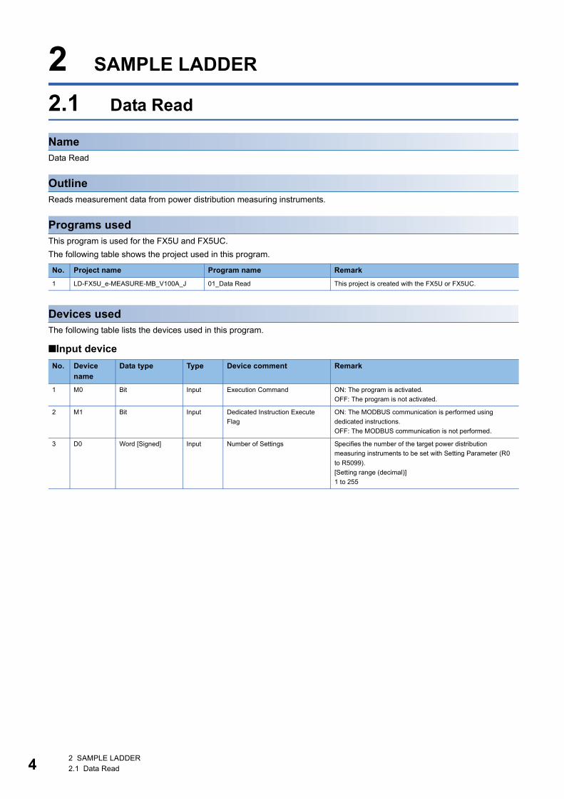
Devices usedThe following table lists the devices used in this program.
■Input device
No. Project name Program name Remark
1 LD-FX5U_e-MEASURE-MB_V100A_J 01_Data Read This project is created with the FX5U or FX5UC.
No. Device name
Data type Type Device comment Remark
1 M0 Bit Input Execution Command ON: The program is activated.
OFF: The program is not activated.
2 M1 Bit Input Dedicated Instruction Execute
Flag
ON: The MODBUS communication is performed using
dedicated instructions.
OFF: The MODBUS communication is not performed.
3 D0 Word [Signed] Input Number of Settings Specifies the number of the target power distribution
measuring instruments to be set with Setting Parameter (R0
to R5099).
[Setting range (decimal)]
1 to 255
2 SAMPLE LADDER2.1 Data Read
2
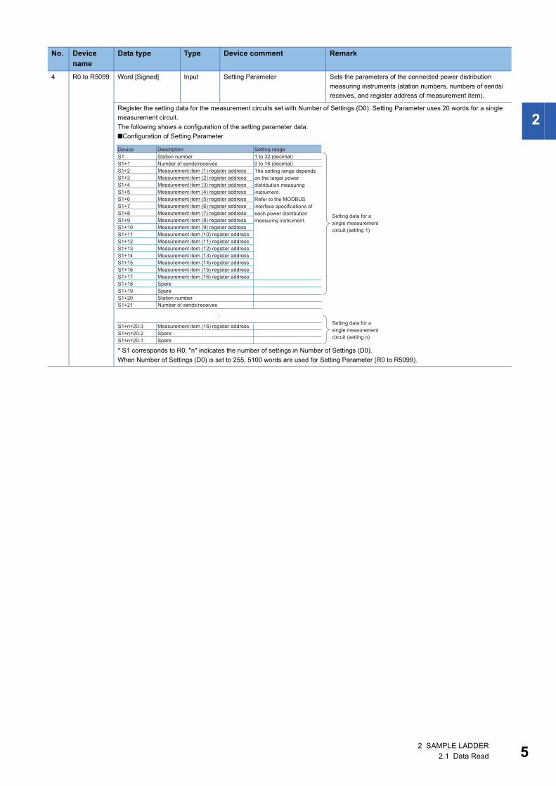
4 R0 to R5099 Word [Signed] Input Setting Parameter Sets the parameters of the connected power distribution
measuring instruments (station numbers, numbers of sends/
receives, and register address of measurement item).
Register the setting data for the measurement circuits set with Number of Settings (D0). Setting Parameter uses 20 words for a single
measurement circuit.
The following shows a configuration of the setting parameter data.
■Configuration of Setting Parameter
* S1 corresponds to R0. "n" indicates the number of settings in Number of Settings (D0).
When Number of Settings (D0) is set to 255, 5100 words are used for Setting Parameter (R0 to R5099).
No. Device name
Data type Type Device comment Remark
DeviceS1S1+1S1+2S1+3S1+4S1+5S1+6S1+7S1+8S1+9S1+10S1+11S1+12S1+13S1+14S1+15S1+16S1+17S1+18S1+19S1+20S1+21
S1+n×20-3S1+n×20-2S1+n×20-1
Station numberNumber of sends/receivesMeasurement item (1) register addressMeasurement item (2) register addressMeasurement item (3) register addressMeasurement item (4) register addressMeasurement item (5) register addressMeasurement item (6) register addressMeasurement item (7) register addressMeasurement item (8) register addressMeasurement item (9) register addressMeasurement item (10) register addressMeasurement item (11) register addressMeasurement item (12) register addressMeasurement item (13) register addressMeasurement item (14) register addressMeasurement item (15) register addressMeasurement item (16) register addressSpareSpareStation numberNumber of sends/receives
Measurement item (16) register addressSpareSpare
1 to 32 (decimal) 0 to 16 (decimal)
Description Setting range
The setting range depends on the target power distribution measuring instrument. Refer to the MODBUS interface specifications of each power distribution measuring instrument.
Setting data for a single measurement circuit (setting 1)
Setting data for a single measurement circuit (setting n)
2 SAMPLE LADDER2.1 Data Read 5
6
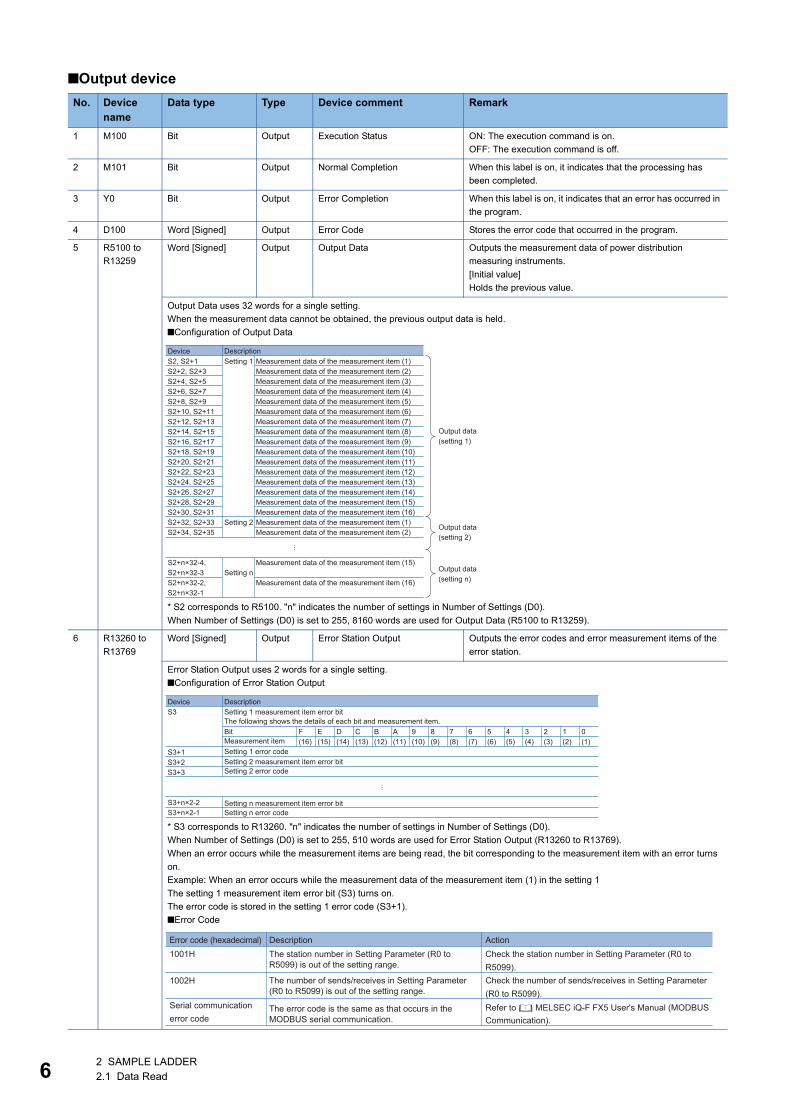
■Output device
No. Device name
Data type Type Device comment Remark
1 M100 Bit Output Execution Status ON: The execution command is on.
OFF: The execution command is off.
2 M101 Bit Output Normal Completion When this label is on, it indicates that the processing has
been completed.
3 Y0 Bit Output Error Completion When this label is on, it indicates that an error has occurred in
the program.
4 D100 Word [Signed] Output Error Code Stores the error code that occurred in the program.
5 R5100 to
R13259
Word [Signed] Output Output Data Outputs the measurement data of power distribution
measuring instruments.
[Initial value]
Holds the previous value.
Output Data uses 32 words for a single setting.
When the measurement data cannot be obtained, the previous output data is held.
■Configuration of Output Data
* S2 corresponds to R5100. "n" indicates the number of settings in Number of Settings (D0).
When Number of Settings (D0) is set to 255, 8160 words are used for Output Data (R5100 to R13259).
6 R13260 to
R13769
Word [Signed] Output Error Station Output Outputs the error codes and error measurement items of the
error station.
Error Station Output uses 2 words for a single setting.
■Configuration of Error Station Output
* S3 corresponds to R13260. "n" indicates the number of settings in Number of Settings (D0).
When Number of Settings (D0) is set to 255, 510 words are used for Error Station Output (R13260 to R13769).
When an error occurs while the measurement items are being read, the bit corresponding to the measurement item with an error turns
on.
Example: When an error occurs while the measurement data of the measurement item (1) in the setting 1
The setting 1 measurement item error bit (S3) turns on.
The error code is stored in the setting 1 error code (S3+1).
■Error Code
DeviceS2, S2+1S2+2, S2+3S2+4, S2+5S2+6, S2+7S2+8, S2+9S2+10, S2+11S2+12, S2+13S2+14, S2+15S2+16, S2+17S2+18, S2+19S2+20, S2+21S2+22, S2+23S2+24, S2+25S2+26, S2+27S2+28, S2+29S2+30, S2+31S2+32, S2+33S2+34, S2+35
S2+n×32-4,S2+n×32-3S2+n×32-2,S2+n×32-1
Setting 1
Setting 2
Setting n
Measurement data of the measurement item (1)Measurement data of the measurement item (2)Measurement data of the measurement item (3)Measurement data of the measurement item (4)Measurement data of the measurement item (5)Measurement data of the measurement item (6)Measurement data of the measurement item (7)Measurement data of the measurement item (8)Measurement data of the measurement item (9)Measurement data of the measurement item (10)Measurement data of the measurement item (11)Measurement data of the measurement item (12)Measurement data of the measurement item (13)Measurement data of the measurement item (14)Measurement data of the measurement item (15)Measurement data of the measurement item (16)Measurement data of the measurement item (1)Measurement data of the measurement item (2)
Measurement data of the measurement item (15)
Measurement data of the measurement item (16)
Output data (setting 1)
Output data (setting 2)
Output data (setting n)
Description
DeviceS3
S3+1S3+2S3+3
S3+n×2-2S3+n×2-1
Setting 1 measurement item error bit The following shows the details of each bit and measurement item.
F E D C B A 9 8 7 6 5 4 3 2 1 0(16) (15) (14) (13) (12) (11) (10) (9) (8) (7) (6) (5) (4) (3) (2) (1)
Description
Setting n measurement item error bit Setting n error code
Setting 2 measurement item error bit Setting 2 error code
Setting 1 error code
Bit Measurement item
Error code (hexadecimal)1001H
1002H
Description Action
Serial communication error code
The error code is the same as that occurs in the MODBUS serial communication.
The number of sends/receives in Setting Parameter(R0 to R5099) is out of the setting range.
The station number in Setting Parameter (R0 toR5099) is out of the setting range.
Check the station number in Setting Parameter (R0 toR5099).
Refer to MELSEC iQ-F FX5 User's Manual (MODBUS Communication).
Check the number of sends/receives in Setting Parameter(R0 to R5099).
2 SAMPLE LADDER2.1 Data Read
2
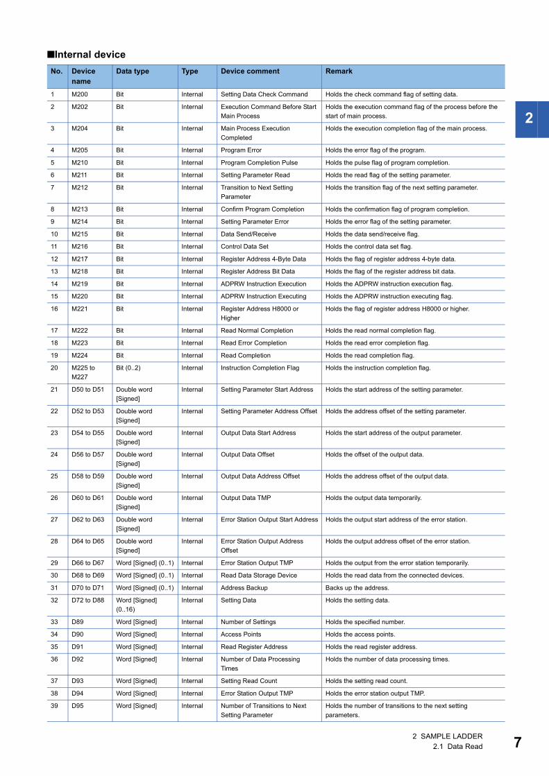
■Internal device
No. Device name
Data type Type Device comment Remark
1 M200 Bit Internal Setting Data Check Command Holds the check command flag of setting data.
2 M202 Bit Internal Execution Command Before Start
Main Process
Holds the execution command flag of the process before the
start of main process.
3 M204 Bit Internal Main Process Execution
Completed
Holds the execution completion flag of the main process.
4 M205 Bit Internal Program Error Holds the error flag of the program.
5 M210 Bit Internal Program Completion Pulse Holds the pulse flag of program completion.
6 M211 Bit Internal Setting Parameter Read Holds the read flag of the setting parameter.
7 M212 Bit Internal Transition to Next Setting
Parameter
Holds the transition flag of the next setting parameter.
8 M213 Bit Internal Confirm Program Completion Holds the confirmation flag of program completion.
9 M214 Bit Internal Setting Parameter Error Holds the error flag of the setting parameter.
10 M215 Bit Internal Data Send/Receive Holds the data send/receive flag.
11 M216 Bit Internal Control Data Set Holds the control data set flag.
12 M217 Bit Internal Register Address 4-Byte Data Holds the flag of register address 4-byte data.
13 M218 Bit Internal Register Address Bit Data Holds the flag of the register address bit data.
14 M219 Bit Internal ADPRW Instruction Execution Holds the ADPRW instruction execution flag.
15 M220 Bit Internal ADPRW Instruction Executing Holds the ADPRW instruction executing flag.
16 M221 Bit Internal Register Address H8000 or
Higher
Holds the flag of register address H8000 or higher.
17 M222 Bit Internal Read Normal Completion Holds the read normal completion flag.
18 M223 Bit Internal Read Error Completion Holds the read error completion flag.
19 M224 Bit Internal Read Completion Holds the read completion flag.
20 M225 to
M227
Bit (0..2) Internal Instruction Completion Flag Holds the instruction completion flag.
21 D50 to D51 Double word
[Signed]
Internal Setting Parameter Start Address Holds the start address of the setting parameter.
22 D52 to D53 Double word
[Signed]
Internal Setting Parameter Address Offset Holds the address offset of the setting parameter.
23 D54 to D55 Double word
[Signed]
Internal Output Data Start Address Holds the start address of the output parameter.
24 D56 to D57 Double word
[Signed]
Internal Output Data Offset Holds the offset of the output data.
25 D58 to D59 Double word
[Signed]
Internal Output Data Address Offset Holds the address offset of the output data.
26 D60 to D61 Double word
[Signed]
Internal Output Data TMP Holds the output data temporarily.
27 D62 to D63 Double word
[Signed]
Internal Error Station Output Start Address Holds the output start address of the error station.
28 D64 to D65 Double word
[Signed]
Internal Error Station Output Address
Offset
Holds the output address offset of the error station.
29 D66 to D67 Word [Signed] (0..1) Internal Error Station Output TMP Holds the output from the error station temporarily.
30 D68 to D69 Word [Signed] (0..1) Internal Read Data Storage Device Holds the read data from the connected devices.
31 D70 to D71 Word [Signed] (0..1) Internal Address Backup Backs up the address.
32 D72 to D88 Word [Signed]
(0..16)
Internal Setting Data Holds the setting data.
33 D89 Word [Signed] Internal Number of Settings Holds the specified number.
34 D90 Word [Signed] Internal Access Points Holds the access points.
35 D91 Word [Signed] Internal Read Register Address Holds the read register address.
36 D92 Word [Signed] Internal Number of Data Processing
Times
Holds the number of data processing times.
37 D93 Word [Signed] Internal Setting Read Count Holds the setting read count.
38 D94 Word [Signed] Internal Error Station Output TMP Holds the error station output TMP.
39 D95 Word [Signed] Internal Number of Transitions to Next
Setting Parameter
Holds the number of transitions to the next setting
parameters.
2 SAMPLE LADDER2.1 Data Read 7
8
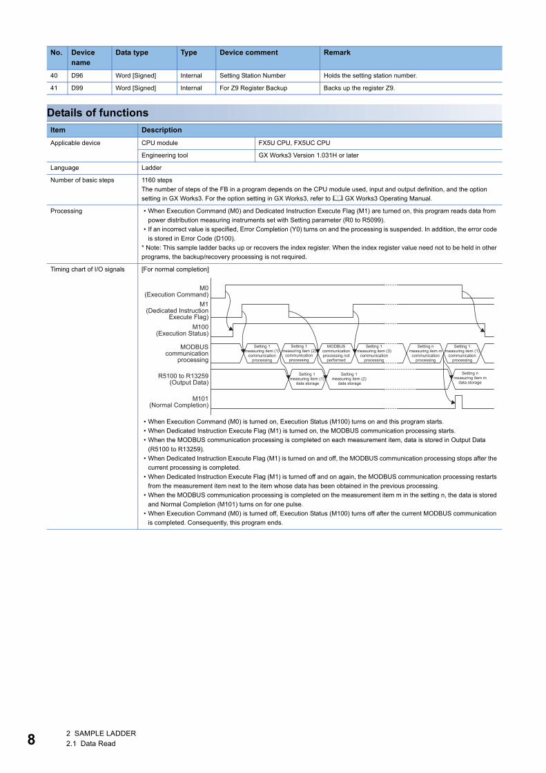
Details of functions
40 D96 Word [Signed] Internal Setting Station Number Holds the setting station number.
41 D99 Word [Signed] Internal For Z9 Register Backup Backs up the register Z9.
Item Description
Applicable device CPU module FX5U CPU, FX5UC CPU
Engineering tool GX Works3 Version 1.031H or later
Language Ladder
Number of basic steps 1160 steps
The number of steps of the FB in a program depends on the CPU module used, input and output definition, and the option
setting in GX Works3. For the option setting in GX Works3, refer to GX Works3 Operating Manual.
Processing • When Execution Command (M0) and Dedicated Instruction Execute Flag (M1) are turned on, this program reads data from
power distribution measuring instruments set with Setting parameter (R0 to R5099).
• If an incorrect value is specified, Error Completion (Y0) turns on and the processing is suspended. In addition, the error code
is stored in Error Code (D100).
* Note: This sample ladder backs up or recovers the index register. When the index register value need not to be held in other
programs, the backup/recovery processing is not required.
Timing chart of I/O signals [For normal completion]
• When Execution Command (M0) is turned on, Execution Status (M100) turns on and this program starts.
• When Dedicated Instruction Execute Flag (M1) is turned on, the MODBUS communication processing starts.
• When the MODBUS communication processing is completed on each measurement item, data is stored in Output Data
(R5100 to R13259).
• When Dedicated Instruction Execute Flag (M1) is turned on and off, the MODBUS communication processing stops after the
current processing is completed.
• When Dedicated Instruction Execute Flag (M1) is turned off and on again, the MODBUS communication processing restarts
from the measurement item next to the item whose data has been obtained in the previous processing.
• When the MODBUS communication processing is completed on the measurement item m in the setting n, the data is stored
and Normal Completion (M101) turns on for one pulse.
• When Execution Command (M0) is turned off, Execution Status (M100) turns off after the current MODBUS communication
is completed. Consequently, this program ends.
No. Device name
Data type Type Device comment Remark
M0 (Execution Command)
M1 (Dedicated Instruction
Execute Flag)M100
(Execution Status)
R5100 to R13259 (Output Data)
MODBUS communication
processing
M101 (Normal Completion)
Setting 1 measuring item (1)
data storage
Setting 1 measuring item (2)
data storage
Setting 1 measuring item (1)
communication processing
MODBUS communication processing not
performed
Setting 1 measuring item (3)
communication processing
Setting 1 measuring item (1)
communication processing
Setting n measuring item m
communication processing
Setting n measuring item m
data storage
Setting 1 measuring item (2)
communication processing
2 SAMPLE LADDER2.1 Data Read
2
Error Code
Version upgrade history
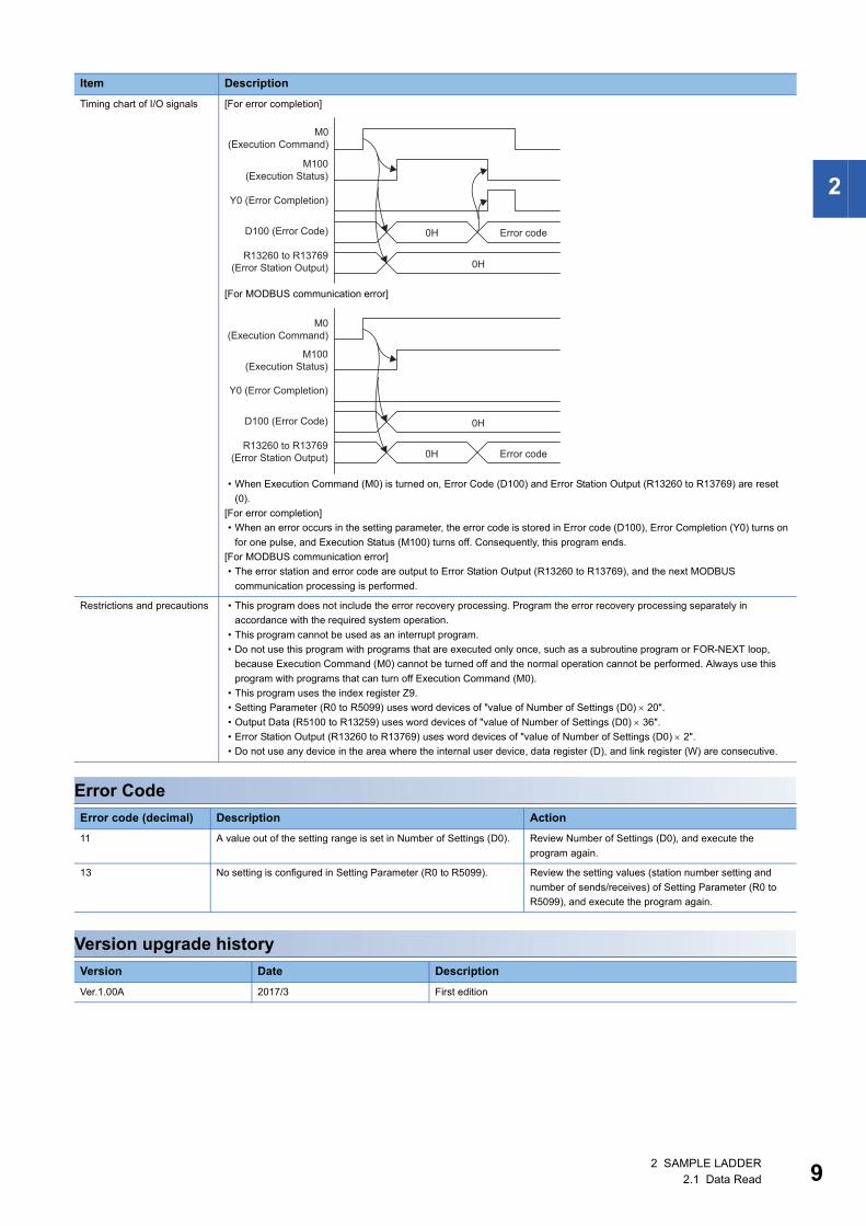
Timing chart of I/O signals [For error completion]
[For MODBUS communication error]
• When Execution Command (M0) is turned on, Error Code (D100) and Error Station Output (R13260 to R13769) are reset
(0).
[For error completion]
• When an error occurs in the setting parameter, the error code is stored in Error code (D100), Error Completion (Y0) turns on
for one pulse, and Execution Status (M100) turns off. Consequently, this program ends.
[For MODBUS communication error]
• The error station and error code are output to Error Station Output (R13260 to R13769), and the next MODBUS
communication processing is performed.
Restrictions and precautions • This program does not include the error recovery processing. Program the error recovery processing separately in
accordance with the required system operation.
• This program cannot be used as an interrupt program.
• Do not use this program with programs that are executed only once, such as a subroutine program or FOR-NEXT loop,
because Execution Command (M0) cannot be turned off and the normal operation cannot be performed. Always use this
program with programs that can turn off Execution Command (M0).
• This program uses the index register Z9.
• Setting Parameter (R0 to R5099) uses word devices of "value of Number of Settings (D0) 20".
• Output Data (R5100 to R13259) uses word devices of "value of Number of Settings (D0) 36".
• Error Station Output (R13260 to R13769) uses word devices of "value of Number of Settings (D0) 2".
• Do not use any device in the area where the internal user device, data register (D), and link register (W) are consecutive.
Error code (decimal) Description Action
11 A value out of the setting range is set in Number of Settings (D0). Review Number of Settings (D0), and execute the
program again.
13 No setting is configured in Setting Parameter (R0 to R5099). Review the setting values (station number setting and
number of sends/receives) of Setting Parameter (R0 to
R5099), and execute the program again.
Version Date Description
Ver.1.00A 2017/3 First edition
Item Description
M0 (Execution Command)
M100 (Execution Status)
Y0 (Error Completion)
R13260 to R13769 (Error Station Output)
D100 (Error Code) 0H Error code
0H
M0 (Execution Command)
M100 (Execution Status)
Y0 (Error Completion)
R13260 to R13769 (Error Station Output)
D100 (Error Code)
0H Error code
0H
2 SAMPLE LADDER2.1 Data Read 9
10
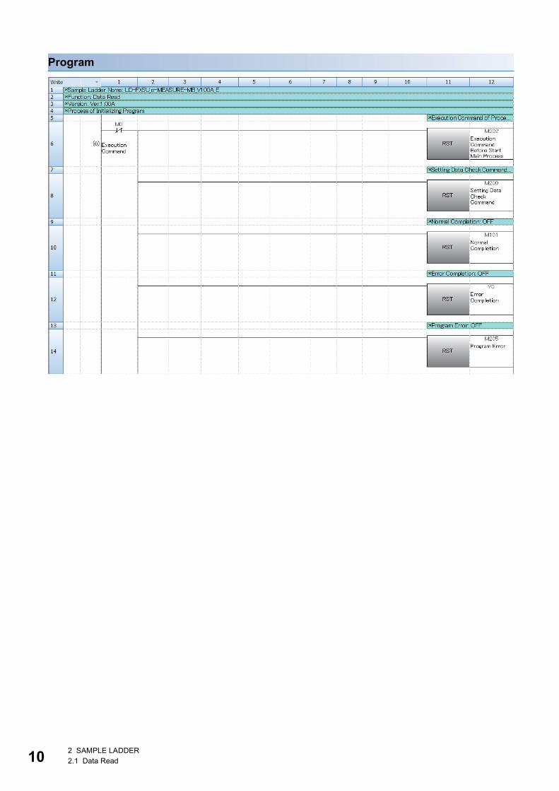
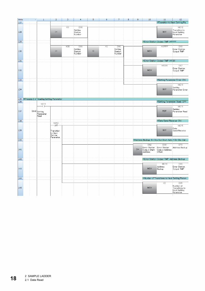
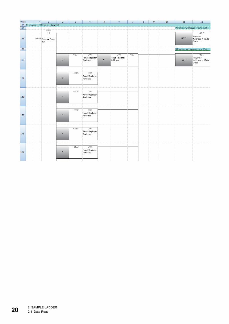
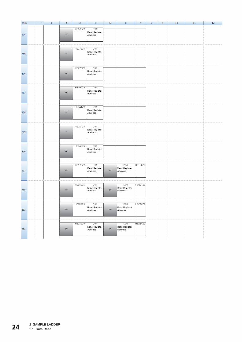
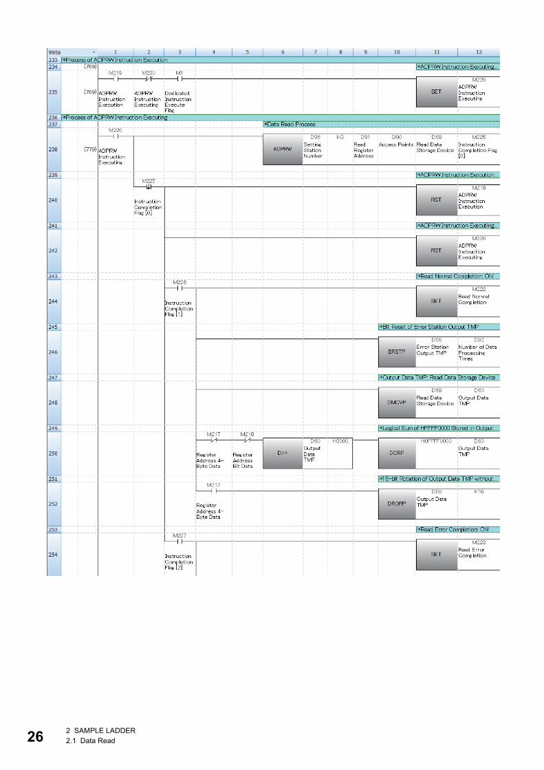
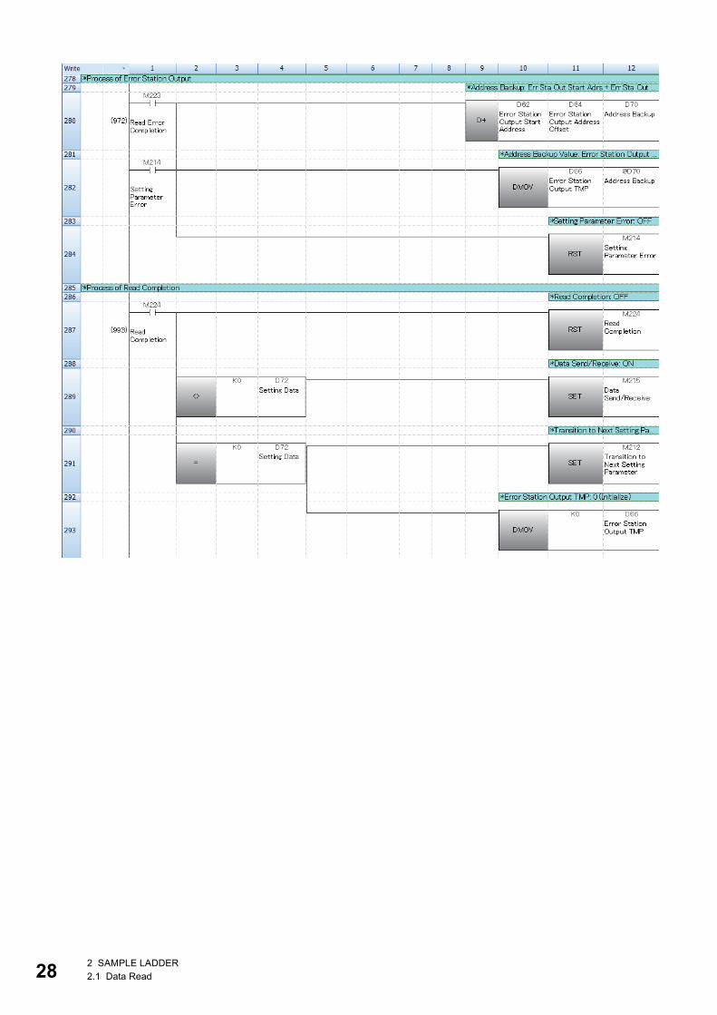
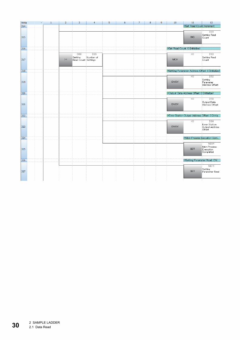
Program
2 SAMPLE LADDER2.1 Data Read

2
2 SAMPLE LADDER2.1 Data Read 11
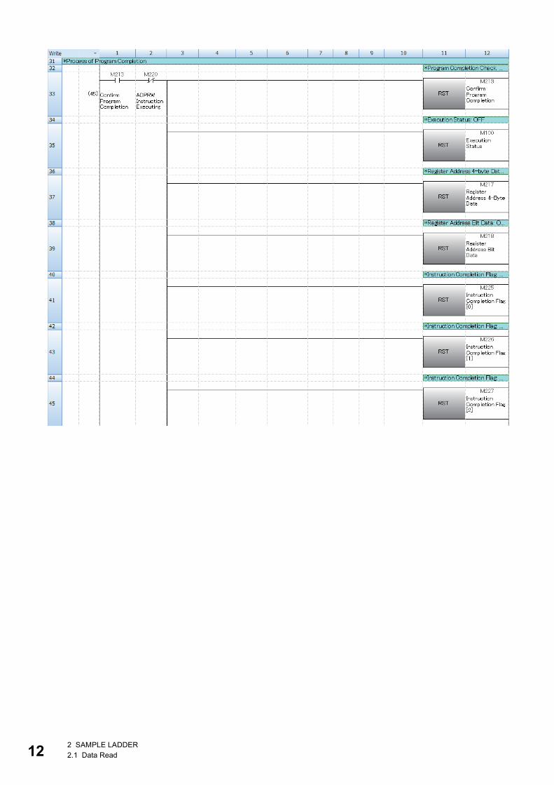
12
2 SAMPLE LADDER2.1 Data Read
2
2 SAMPLE LADDER2.1 Data Read 13
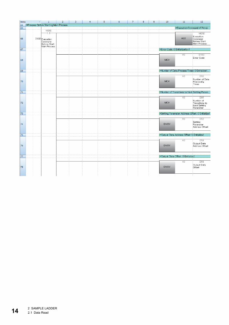
14
2 SAMPLE LADDER2.1 Data Read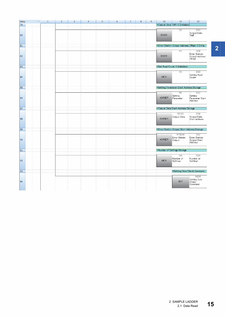
2
2 SAMPLE LADDER2.1 Data Read 15

16
2 SAMPLE LADDER2.1 Data Read
2
2 SAMPLE LADDER2.1 Data Read 17
18
2 SAMPLE LADDER2.1 Data Read
2
2 SAMPLE LADDER2.1 Data Read 19
20
2 SAMPLE LADDER2.1 Data Read
2
2 SAMPLE LADDER2.1 Data Read 21

22
2 SAMPLE LADDER2.1 Data Read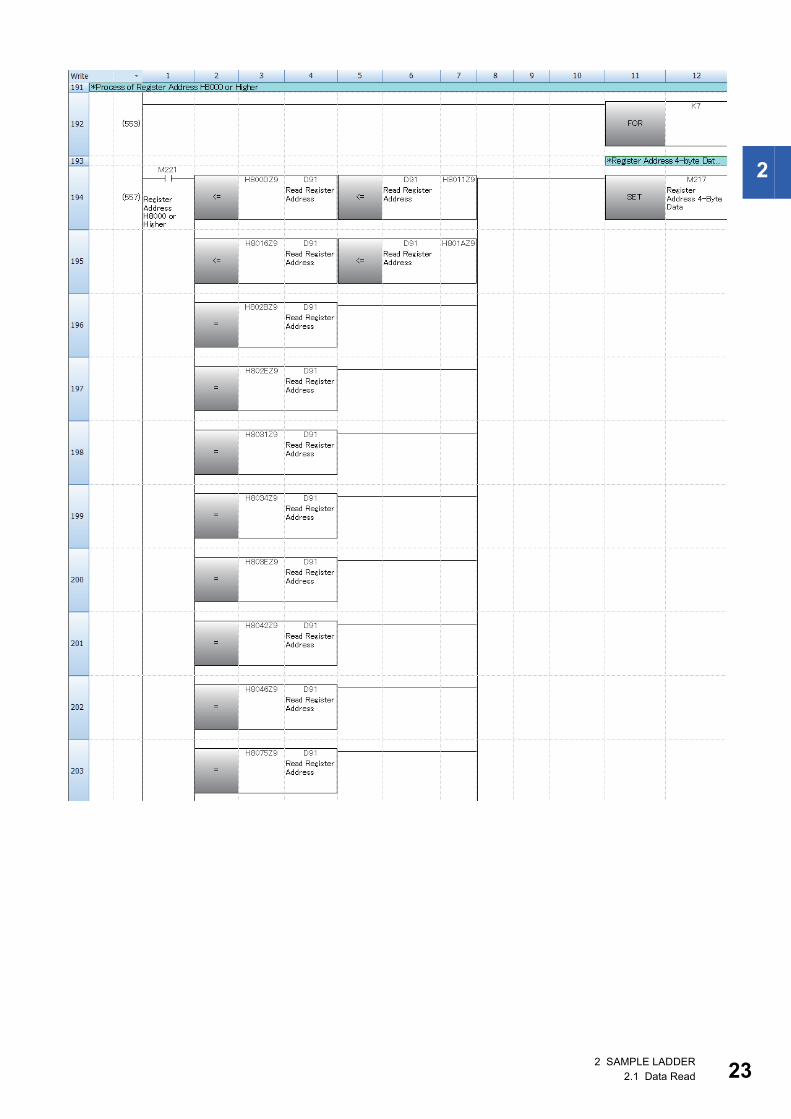
2
2 SAMPLE LADDER2.1 Data Read 23
24
2 SAMPLE LADDER2.1 Data Read
2
2 SAMPLE LADDER2.1 Data Read 25
26
2 SAMPLE LADDER2.1 Data Read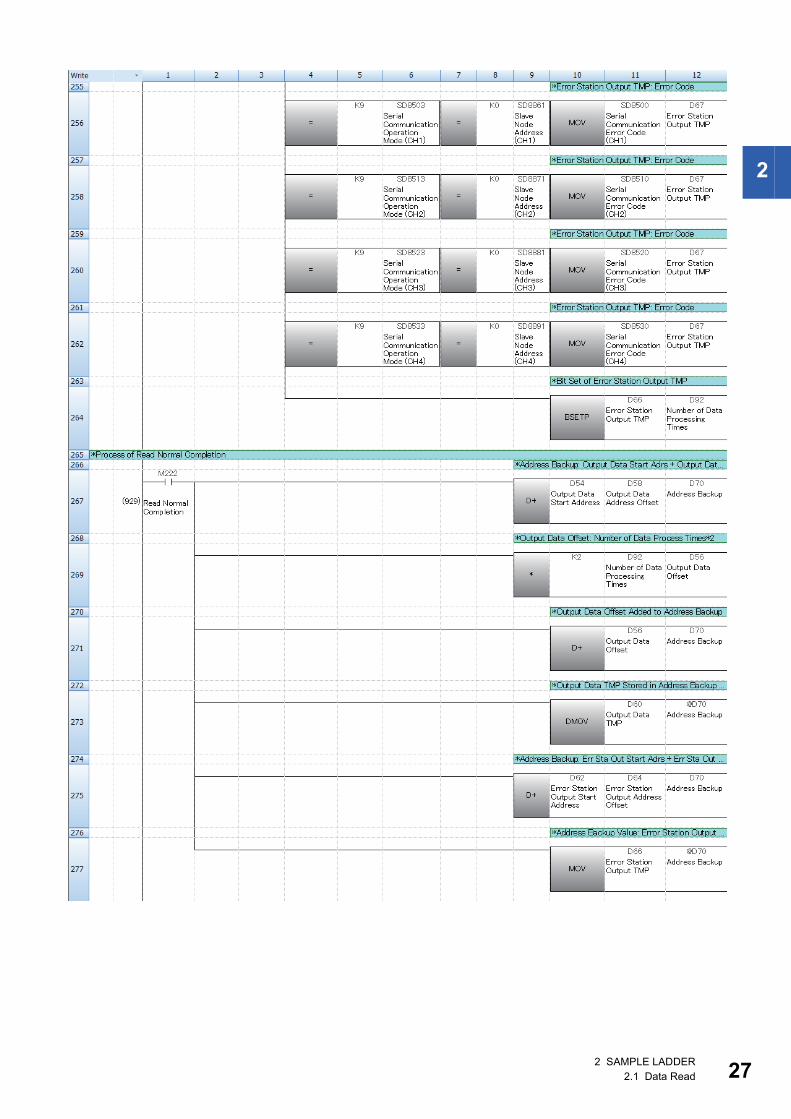
2
2 SAMPLE LADDER2.1 Data Read 27
28
2 SAMPLE LADDER2.1 Data Read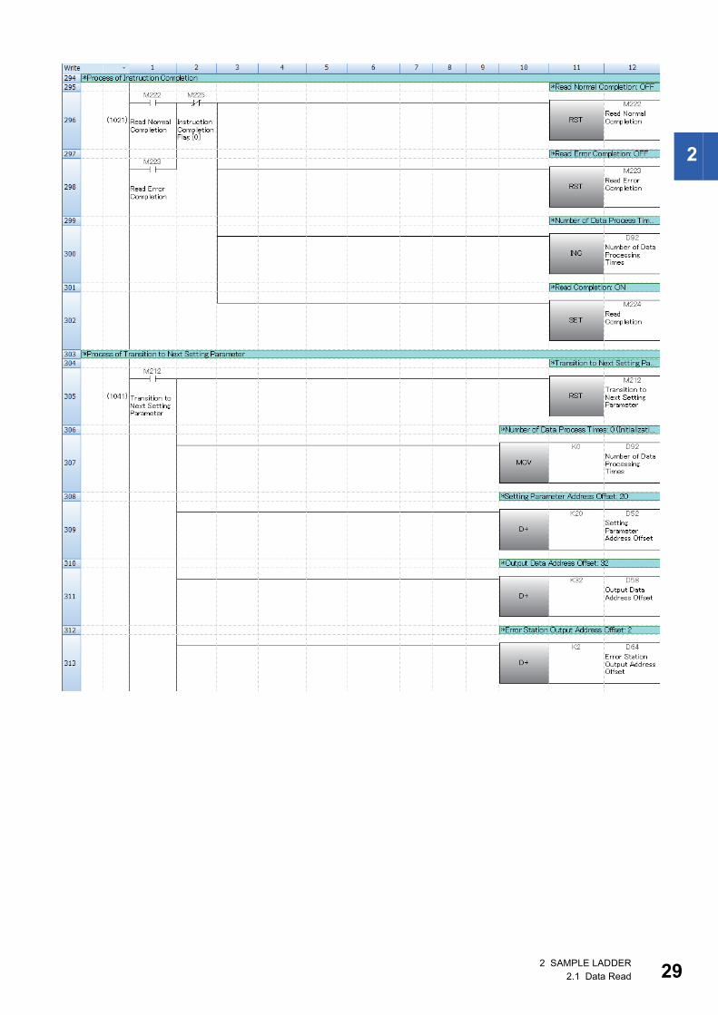
2
2 SAMPLE LADDER2.1 Data Read 29
30
2 SAMPLE LADDER2.1 Data Read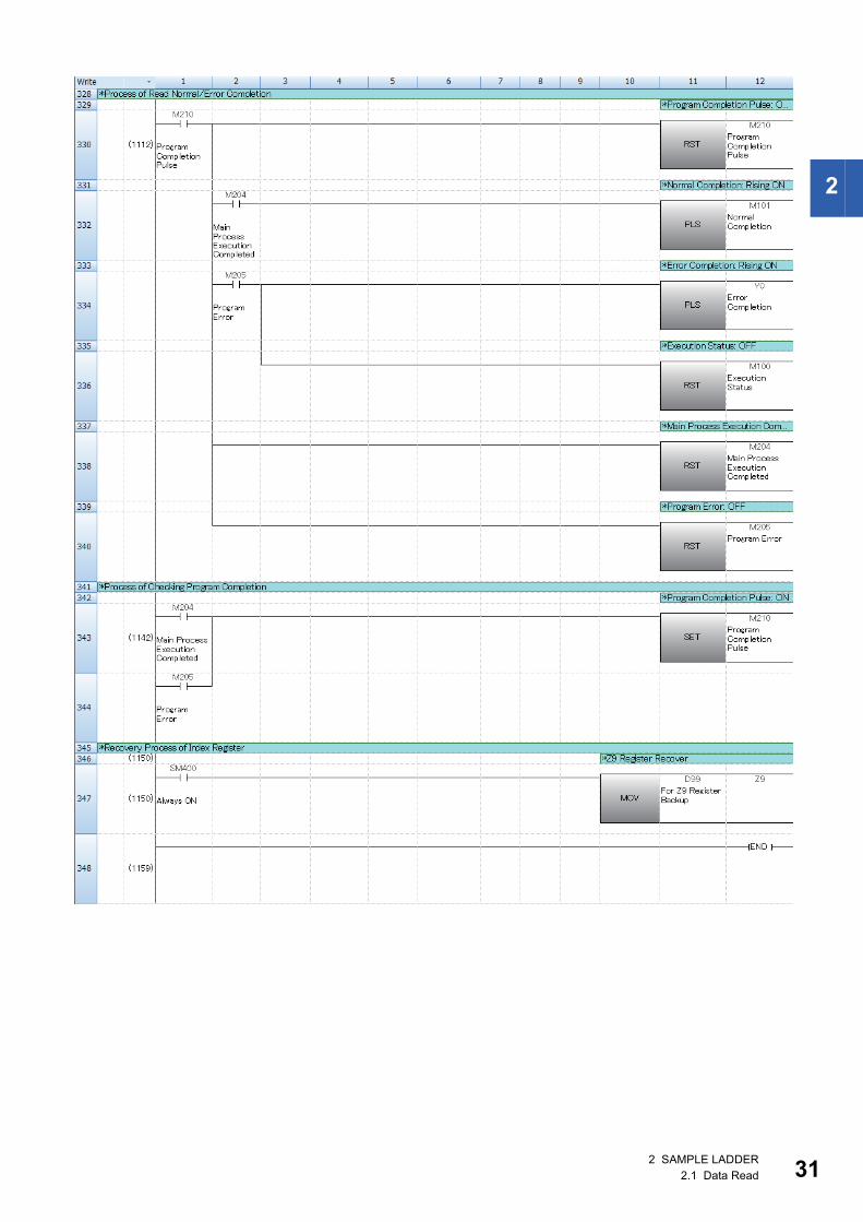
2
2 SAMPLE LADDER2.1 Data Read 31
32
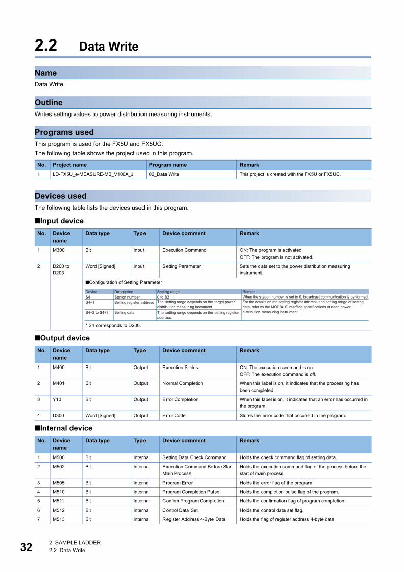
2.2 Data Write
NameData Write
OutlineWrites setting values to power distribution measuring instruments.
Programs usedThis program is used for the FX5U and FX5UC.
The following table shows the project used in this program.
Devices usedThe following table lists the devices used in this program.
■Input device
■Output device
■Internal device
No. Project name Program name Remark
1 LD-FX5U_e-MEASURE-MB_V100A_J 02_Data Write This project is created with the FX5U or FX5UC.
No. Device name
Data type Type Device comment Remark
1 M300 Bit Input Execution Command ON: The program is activated.
OFF: The program is not activated.
2 D200 to
D203
Word [Signed] Input Setting Parameter Sets the data set to the power distribution measuring
instrument.
■Configuration of Setting Parameter
* S4 corresponds to D200.
No. Device name
Data type Type Device comment Remark
1 M400 Bit Output Execution Status ON: The execution command is on.
OFF: The execution command is off.
2 M401 Bit Output Normal Completion When this label is on, it indicates that the processing has
been completed.
3 Y10 Bit Output Error Completion When this label is on, it indicates that an error has occurred in
the program.
4 D300 Word [Signed] Output Error Code Stores the error code that occurred in the program.
No. Device name
Data type Type Device comment Remark
1 M500 Bit Internal Setting Data Check Command Holds the check command flag of setting data.
2 M502 Bit Internal Execution Command Before Start
Main Process
Holds the execution command flag of the process before the
start of main process.
3 M505 Bit Internal Program Error Holds the error flag of the program.
4 M510 Bit Internal Program Completion Pulse Holds the completion pulse flag of the program.
5 M511 Bit Internal Confirm Program Completion Holds the confirmation flag of program completion.
6 M512 Bit Internal Control Data Set Holds the control data set flag.
7 M513 Bit Internal Register Address 4-Byte Data Holds the flag of register address 4-byte data.
DeviceS4S4+1
S4+2 to S4+3
Station number Setting register address Setting data
0 to 32Description Setting range Remark
The setting range depends on the target power distribution measuring instrument.
The setting range depends on the setting register address.
For the details on the setting register address and setting range of setting data, refer to the MODBUS interface specifications of each power distribution measuring instrument.
When the station number is set to 0, broadcast communication is performed.
2 SAMPLE LADDER2.2 Data Write

2
Details of functions
8 M514 to
M516
Bit (0..2) Internal Instruction Completion Flag Holds the instruction completion flag.
9 M517 Bit Internal Write Normal Completion Holds the write normal completion flag.
10 M518 Bit Internal Write Error Completion Holds the write error completion flag.
11 M519 Bit Internal ADPRW Instruction Execution Holds the ADPRW instruction execution flag.
12 D250 to
D251
Double word
[Signed]
Internal Write Data Storage Device Holds the data written to the connected devices.
13 D252 Word [Signed] Internal Access Points Holds the access points.
14 D253 to
D256
Word [Signed] (0..3) Internal Setting Parameter Holds the setting parameter.
15 D299 Word [Signed] Internal For Z9 Register Backup Backs up the register Z9.
Item Description
Applicable device CPU module FX5U CPU, FX5UC CPU
Engineering tool GX Works3 Version 1.031H or later
Language Ladder
Number of basic steps 550 steps
The number of steps of the FB in a program depends on the CPU module used, input and output definition, and the option
setting in GX Works3. For the option setting in GX Works3, refer to GX Works3 Operating Manual.
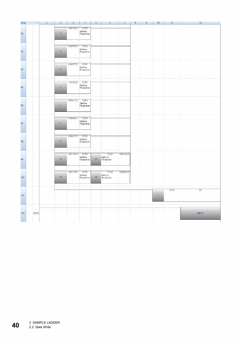
Processing • When Execution Command (M300) is turned on, the items of Setting Parameter (D200 to D203) are set to the power
distribution measuring instrument.
• If an incorrect value is specified, Error Completion (Y10) turns on and the processing is suspended. In addition, the error
code is stored in Error Code (D300).
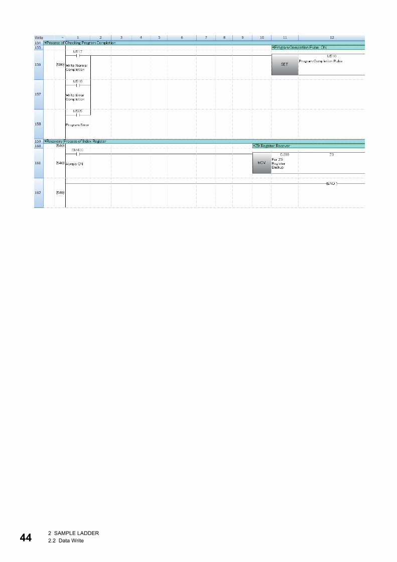
* Note: This sample ladder backs up or recovers the index register. When the index register value need not to be held in other
programs, the backup/recovery processing is not required.
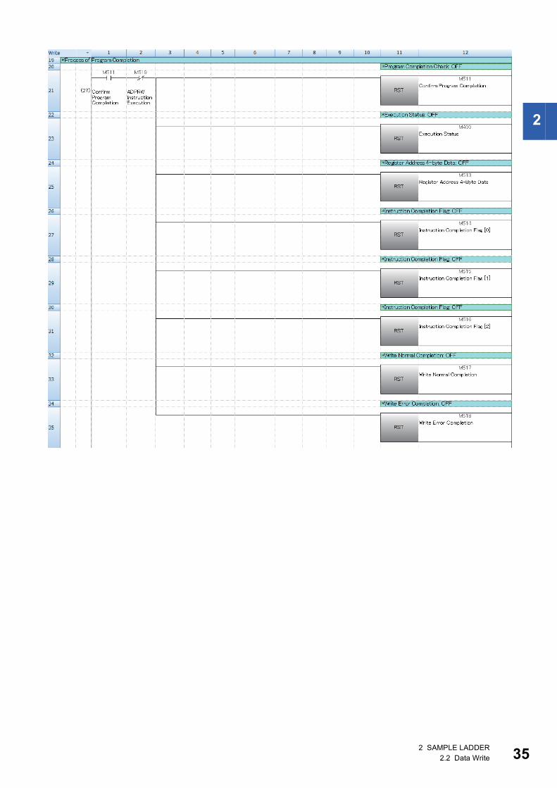
Timing chart of I/O signals [For normal completion]
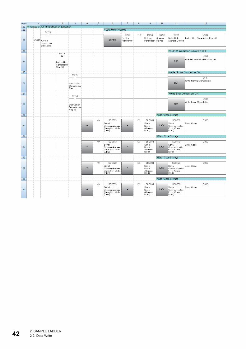
• When Execution Command (M300) is turned on, Execution Status (M400) turns on and the MODBUS communication
processing is performed.
• After the MODBUS communication processing is completed, Normal Completion (M401) turns on for one pulse and
Execution Status (M400) turns off. Consequently, this program ends.
[For error completion]
• When Execution Command (M300) is turned on, Error Code (D300) is reset (0).
• The error code is stored in Error Code (D300), Error Completion (Y10) turns on for one pulse, and Execution Status (M400)
turns off. Consequently, this program ends.
Restrictions and precautions • This program does not include the error recovery processing. Program the error recovery processing separately in
accordance with the required system operation.
• This program cannot be used as an interrupt program.
• Do not use this program with programs that are executed only once, such as a subroutine program or FOR-NEXT loop,
because Execution Command (M300) cannot be turned off and the normal operation cannot be performed. Always use this
program with programs that can turn off Execution Command (M300).
• This program uses the index register Z9.
No. Device name
Data type Type Device comment Remark
M300 (Execution Command)
M400 (Execution Status)
M401 (Normal Completion)
MODBUS communication
processing
M300 (Execution Command)
M400 (Execution Status)
Y10 (Error Completion)
D300 (Error Code) 0H Error code
2 SAMPLE LADDER2.2 Data Write 33
34
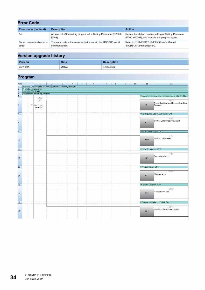
Error Code
Version upgrade history
Program
Error code (decimal) Description Action
14 A value out of the setting range is set in Setting Parameter (D200 to
D203).
Review the station number setting of Setting Parameter
(D200 to D203), and execute the program again.
Serial communication error
code
The error code is the same as that occurs in the MODBUS serial
communication.
Refer to MELSEC iQ-F FX5 User's Manual
(MODBUS Communication).
Version Date Description
Ver.1.00A 2017/3 First edition
2 SAMPLE LADDER2.2 Data Write
2
2 SAMPLE LADDER2.2 Data Write 35

36
2 SAMPLE LADDER2.2 Data Write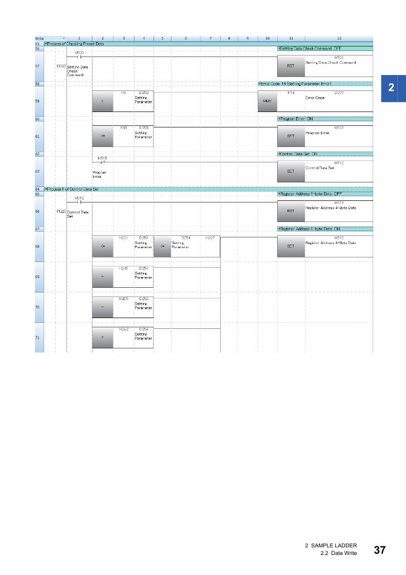
2
2 SAMPLE LADDER2.2 Data Write 37

38
2 SAMPLE LADDER2.2 Data Write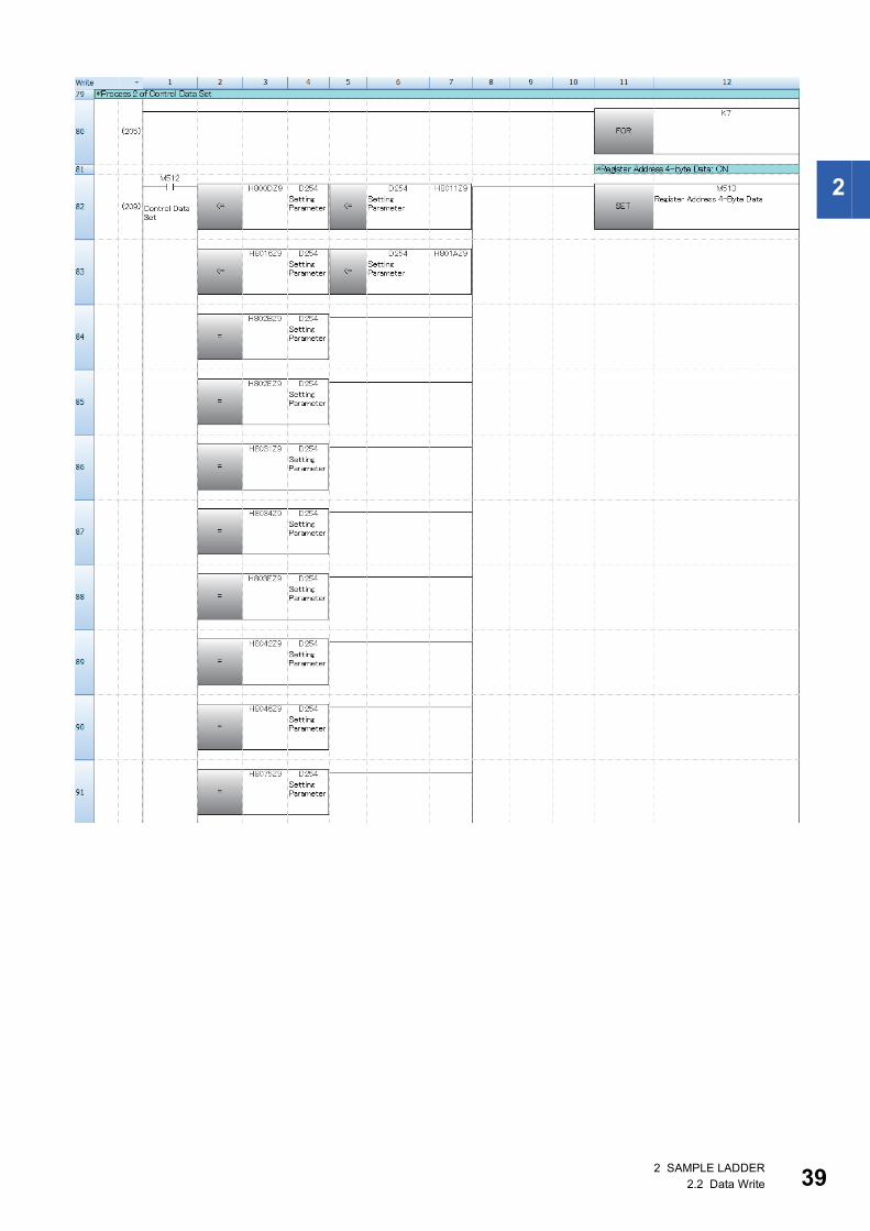
2
2 SAMPLE LADDER2.2 Data Write 39
40
2 SAMPLE LADDER2.2 Data Write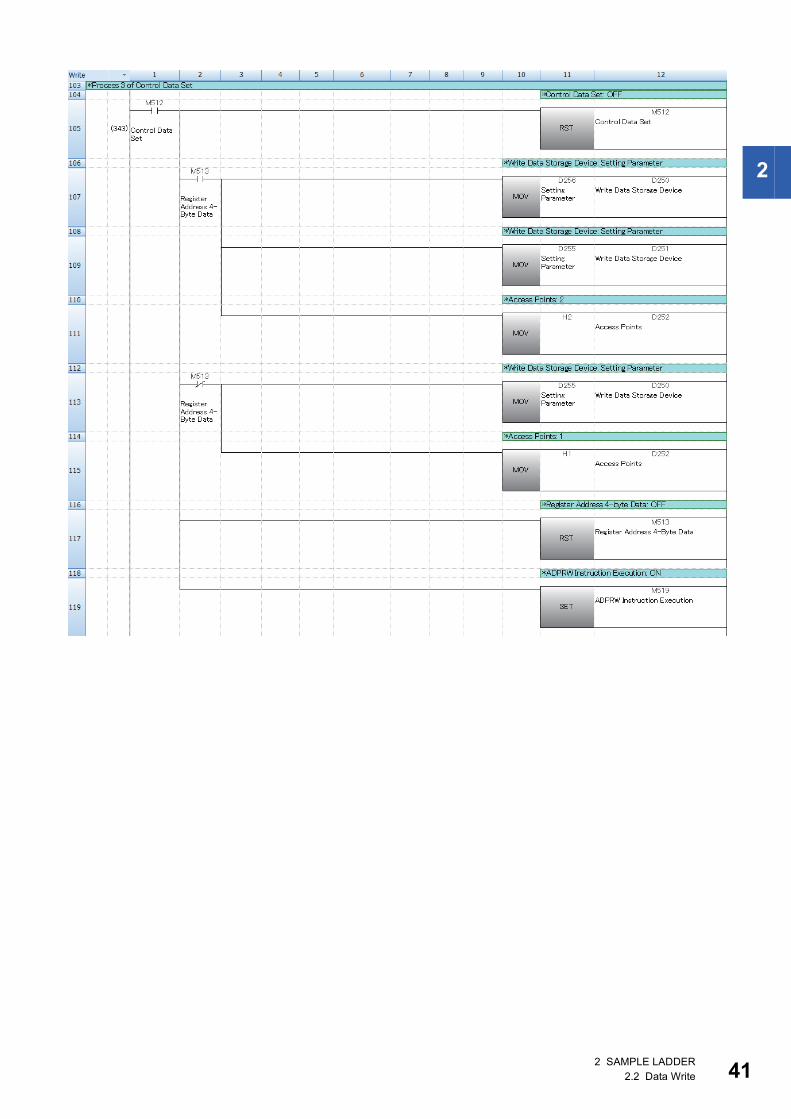
2
2 SAMPLE LADDER2.2 Data Write 41
42
2 SAMPLE LADDER2.2 Data Write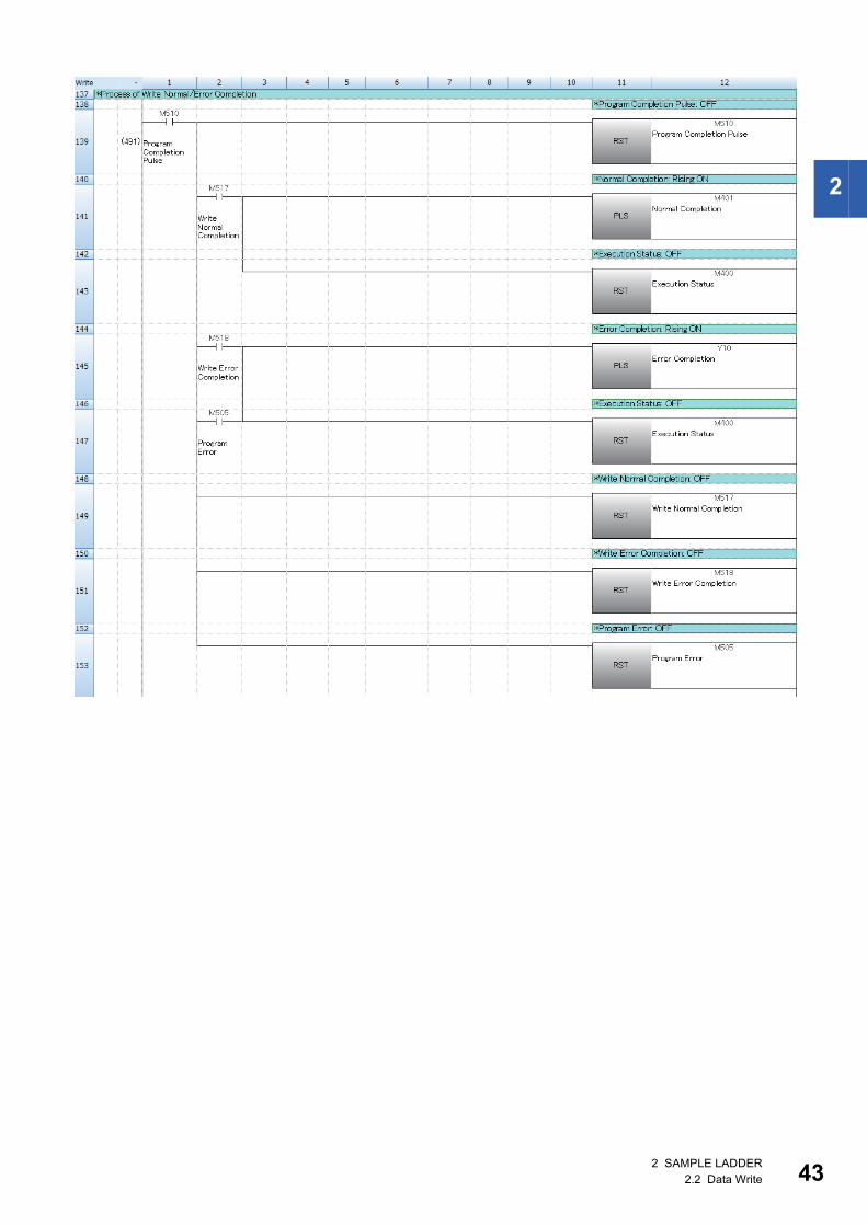
2
2 SAMPLE LADDER2.2 Data Write 43
44
2 SAMPLE LADDER2.2 Data Write
2
MEMO
2 SAMPLE LADDER2.2 Data Write 45

46
REVISIONS
Japanese manual number: JY997D74701A
2017 MITSUBISHI ELECTRIC CORPORATION
TRADEMARKSMODBUS is a registered trademark of Schneider Electric SA.
The company name and the product name to be described in this manual are the registered trademarks or trademarks of
each company.
Revision date Revision Description
March 2017 A First edition
This manual confers no industrial property rights of any other kind, nor does it confer any patent licenses. Mitsubishi Electric Corporation cannot be held
responsible for any problems involving industrial property rights which may occur as a result of using the contents noted in this manual.


Manual number: JY997D74801A
Specifications subject to change without notice.
When exported from Japan, this manual does not require application to theMinistry of Economy, Trade and Industry for service transaction permission.
HEAD OFFICE : TOKYO BUILDING, 2-7-3 MARUNOUCHI, CHIYODA-KU, TOKYO 100-8310, JAPANNAGOYA WORKS : 1-14 , YADA-MINAMI 5-CHOME , HIGASHI-KU, NAGOYA , JAPAN