mel 110 laboratory 1 (to be done in cagi lab. room: iii...
TRANSCRIPT

DEPARTMENT OF MECHANICAL ENGINEERING, IIT DELHI MEL 110 LABORATORY 1 (to be done in CAGI Lab. Room: III 331) DURATION: 3 Hrs 50 Min. Note: Missing dimensions may be suitably assumed.
Exercise 1: Visualize orthographic and isometric views of 3D models/objects: Open Autodesk Inventor by double clicking its shortcut on desktop or by selecting it from program list.
1. Use Open command to open an existing inventor part file (all the part files have an extension of .ipt. ‘ipt’ is the abbreviation for inventor part file).
2. Go to Public Documents>Autodesk>Inventor 2011>tutorial files>PivotBracket.ipt (or any other part file) and click open. The part file will be active now.
3. Keep the cursor at any of the menu items for a while to see the details of operations that can be performed by using that command.
4. Use the View cube displayed at the top right hand corner in the active area. Click the cube corners to snap the 3D model to isometric views and click the faces for orthographic views. Click the Home button in the view cube to return to a user-defined base view.
5. Use the Navigate command in the main View tab to zoom, pan, rotate (orbit) the 3D model. Click on the view face command and select any face of this model. Click on this face again. New tools appear on this face. Bring the cursor to the edit sketch tool to view the details of this face. Navigate command can also be accessed from the right side of active sheet
6. Close the active file. Exercise 2: Create a sketch with lines:
1. Click the projects command located in the launch panel and select the default project and click done. Launch panel is part of the Get Started tab.
2. Create a new part file. In the Get Started tab, go to new > Metric > standard (mm).ipt and click OK. This will open the sketch mode with a default file name Part1 (you can later save this part with a different name. It will have an extension .ipt). If the sketch mode is not activated, then select sketch 1 from the browser window which is located on the left side below the main tab.
3. Select a working plane (XY, XZ or YZ plane) under origins tab from the browser window to create a 2D sketch or else use the default working plane.
4. Use the 2D sketch commands to create the following sketch using lines. Press esc button on the keyboard to exit out of any command.
5. In order to view the different axes, right click the x-axis in the browser window and select visibility. The x-axis will be visible now. Similarly do this for the remaining axes and/or for all the planes.
6. Add dimension to the sketch from the dimension command located in the constrain command by clicking the line (that need to be dimensioned) and then dragging the mouse.
7. Select the Finish sketch command to exit the sketcher after completing the sketch and close the active file.
Exercise 3: Create a profile with tangencies:
1. Repeat steps 1 to 3 of exercise 2. To draw any construction feature: go to Sketch>Format>Construction. 2. Use the 2D sketch commands to create the following sketch using lines, circles and tangential arcs. 3. Select the ‘show constraints’ command from the constrain command located in the sketch panel of the sketch tab (or else click right button of mouse and activate “show all constraints”). 4. Add constrain from the constrain command located in the sketch panel of the sketch tab. 5. Add dimension to the sketch from the dimension command located in the constrain command by clicking the line (that need to be dimensioned) and then dragging the mouse. 6. Select the Finish sketch command to exit the sketcher. 7. Use the Extrude command to extrude the sketch as shown in the figure. 8. close the active file.

Exercise 4: Create a Drawing of a solid model:
1. Create a new drawing file. In the Get Started tab, go to new > Metric > ANSI(mm).idw and click OK. This will open a new drawing with a default file name Drawing1 (you can later save this drawing with the same name as that of the part file name or a different one. It will have an extension .dwg).
2. In the Place Views tab, click Base. This will open a window of Drawing View. Open an existing part file Documents>Autodesk>Inventor 2011>tutorial files>PivotBracket.ipt and select a suitable scale, orientation and style and click OK.
3. In the Place Views tab, click Projected and move the mouse at the left, right, top or bottom side of the base view to obtain the corresponding views and then click right mouse button and click create.
4. In the Annotate tab, click Dimension. Add dimension to the drawing view by clicking the line/feature (that need to be dimensioned) and then dragging the mouse to a suitable distance to place the dimension line.
5. Click right mouse button and select Done. Problem 1: Create the sketch shown in figure 1 as per the given dimensions. Use the Extrude command (extrusion 25 mm) to
create a solid model of this sketch and obtain the orthographic projections. (1 marks) Problem 2: Create the sketch shown in figure 2 as per the given dimensions. Use the Extrude command to create a solid model of
this sketch and obtain the orthographic projections. (2 marks)
Problem 3: Create the sketch shown in figure 3 as per the given dimensions. Use the Revolve command (axis x-x) to create a solid
model of this sketch and obtain the orthographic projections. (2 marks)
Fig 1 Fig 2
x x

DEPARTMENT OF MECHANICAL ENGINEERING, IIT DELHI
Graphic Science MEL 110 LABORATORY 2 DURATION: 3 Hrs 50 Min. MARKS 10
NOTE: No drawing instruments like metric scale, compass, divider, drafter etc. are permitted except Tracing sheet Pad with a graph paper, H & HB grade pencils and eraser. Q1:- Write your name, entry number and group number using following (free hand lettering):
ABCDEFGHIJKLMNOPQRSTUVWXYZ 1234567890
Take the height of letter/digit =5mm, Width of letter/digit =4mm (except width of letter I which is 1 mm, for M and W which are 5 mm and for digit 1 which is 1 mm), Gap between line= 5mm, Gap between letters/digits, letter & comma, letter & full stop=1mm and Gap between words=5mm. Q2:- Draw the symbols for 1st and 3rd angle projection systems. Q3:- Sketch the following lines used for
(a) Hidden Edges line (b) Centre line (c) Construction line (d) Outline (e) Dimension line
Q4:-Draw the orthographic projections, indicating dimensions, of the following points, about common X-Y line. Mention the projection system (I, II, III or IV angle).
(a) 40 mm above Horizontal Plane and 50 mm in front of Vertical Plane. (b) 70 mm above Horizontal Plane and 30 mm behind Vertical Plane. (c) 50 mm below Horizontal Plane and 60 mm behind Vertical Plane. (d) 40 mm below Horizontal Plane and 50 mm in front of Vertical Plane.
Q5:- Draw two orthographic projections of following (Choose your own dimension if not given)
(a) a horizontal line 40 mm from top plane & at an angle of 600 to Vertical plane. (b) a vertical plane ABC at a distance of 5cm from frontal plane. (c) a horizontal plane ABC at a distance of 5cm from top plane (d) an inclined plane perpendicular to top plane. (e) an inclined plane perpendicular to front plane. (f) two non intersecting oblique lines. (g) two non intersecting parallel lines which are oblique to the principal plane.
Q6:- Assume height as 70mm, diameter as 60mm and side as 50mm for following (no need to dimension the views):
a) Sketch two necessary orthographic views of a Square prism. b) Sketch two necessary orthographic views of a Square pyramid. c) Sketch two necessary orthographic views of a Right circular cone.
Marks (0.7x3)=2.1
Marks 0.5 x7=3.5
Marks(0.25x4)= 1
Marks 1
Marks 1
Marks 0.28x5=1.4

DEPARTMENT OF MECHANICAL ENGINEERING, IIT DELHI Graphic Science MEL 110 LABORATORY 3 DURATION: 3 Hrs 50 Min. NOTE: No drawing instruments like metric scale, compass, divider, drafter etc. are permitted except Tracing sheet Pad with a graph paper, HB & H pencils and eraser. Note: Choose a suitable scale only if the required views can’t be accommodated on a single tracing sheet. ‘X’ indicates the front viewing direction. Q1 & 2:- Sketch three orthographic views of the objects (fig 1 & fig 2) in I angle projection and dimension the views according to aligned system of dimensioning. Q3, 4, 5 & 6:- Sketch the orthographic views of the objects along with marking of the corresponding surfaces in front view, top view and side view in III angle projection and dimension the views according to the unidirectional system of dimensioning (figures 3, 4 & 5).
HELP:
• Unidirectional system: Place all dimension values and notes horizontally, so that those can be read from left to right.
• Aligned system: Place all dimension values and notes vertically or horizontally, depending on the placement of the feature to be dimnesioned.
Fig 1 Fig 2
Fig 3 Fig 4
Fig 5
3 marks
1.5 marks1.5 marks
2.25 marks1.75 marks
4
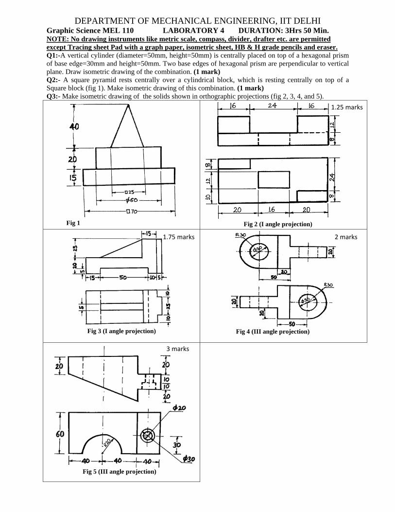
DEPARTMENT OF MECHANICAL ENGINEERING, IIT DELHI Graphic Science MEL 110 LABORATORY 4 DURATION: 3Hrs 50 Min. NOTE: No drawing instruments like metric scale, compass, divider, drafter etc. are permitted except Tracing sheet Pad with a graph paper, isometric sheet, HB & H grade pencils and eraser. Q1:-A vertical cylinder (diameter=50mm, height=50mm) is centrally placed on top of a hexagonal prism of base edge=30mm and height=50mm. Two base edges of hexagonal prism are perpendicular to vertical plane. Draw isometric drawing of the combination. (1 mark) Q2:- A square pyramid rests centrally over a cylindrical block, which is resting centrally on top of a Square block (fig 1). Make isometric drawing of this combination. (1 mark) Q3:- Make isometric drawing of the solids shown in orthographic projections (fig 2, 3, 4, and 5).
Fig 1
Fig 4 (III angle projection) Fig 3 (I angle projection)
Fig 2 (I angle projection)
Fig 5 (III angle projection)
1.25 marks
1.75 marks
3 marks
2 marks
DEPARTMENT OF MECHANICAL ENGINEERING, IIT DELHI
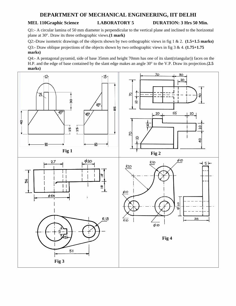
MEL 110Graphic Science LABORATORY 5 DURATION: 3 Hrs 50 Min.
Q1:- A circular lamina of 50 mm diameter is perpendicular to the vertical plane and inclined to the horizontal plane at 30°. Draw its three orthographic views.(1 mark) Q2:-Draw isometric drawings of the objects shown by two orthographic views in fig 1 & 2. (1.5+1.5 marks) Q3:- Draw oblique projections of the objects shown by two orthographic views in fig 3 & 4. (1.75+1.75 marks) Q4:- A pentagonal pyramid, side of base 35mm and height 70mm has one of its slant(triangular)) faces on the H.P. and the edge of base contained by the slant edge makes an angle 30° to the V.P. Draw its projection.(2.5 marks)
Fig 4
Fig 3
Fig 2 Fig 1

DEPARTMENT OF MECHANICAL ENGINEERING, IIT DELHI MEL 110 Graphic Science LABORATORY 6 DURATION: 3 Hrs 50 Min. NOTE: Draw the specified views with dimensions and proper notations. Use III angle projection.
Q1: A thin regular pentagonal plate is of 30mm edge and thickness 5 mm. One edge of the lower pentagon is in horizontal plane and perpendicular to the vertical plane, while farthest corner of lower pentagon from this edge is 30mm above the horizontal plane. Draw three necessary orthographic projections of the plate. (2.0 marks)
Q2: Sectional front view & “top view without section” (fig.1). (1.25 marks) Q3: Front view (without section) and “Sectional side view” (fig 2). (1.75 marks) Q4: Sectional front view & “top view without section” (fig 3). (2.5 marks) Q5: Half Sectional front view & half sectional side view (fig 4). (2. 5 marks)
Fig 3
Fig 2
Fig 4
X
Fig 1
160
X X
20

DEPARTMENT OF MECHANICAL ENGINEERING, IIT DELHI MEL 110 ULABORATORY 7 (to be done in CAGI Lab. Room: III 331) U DURATION: 3 Hrs 50 Min.
Note: If any dimensions are missing they should be suitably assumed. All the dimensions are in mm. UProblem 1:U Make solid models of the objects shown in figures 1, 2 and 3 and obtain the orthographic projections. (1+2+2 mark) UProblem 2:U Make solid models of the figures 4, 5 and 6 and obtain their isometric views. (1+2+2 marks)
Fig 5 Fig 6
Fig 3
Fig 2 Fig 1
Fig 4 All three orthographic projections are identical
80

DEPARTMENT OF MECHANICAL ENGINEERING, IIT DELHI Graphic Science MEL 110 LABORATORY 8 DURATION: 3 Hrs 50 Min. Note: 10% marks will be deducted for improper line work. Q1:‐Find the piercing point and the true angle of inclination of the line P(20,10,0), Q(10,25,40) with the plane A( 10, 30, 0), B(30, 20, 40), C(10, 0, 40). (Marks: 2.0)
Figure 1: Coordinate System for Q1
Figure 2: Coordinate System for Q1
Q2:‐A light house has a helical staircase running inside it. The light house has 3 stories and the diameter of the building is 10 meters. Each story is 5 meters high. There are 2 windows along the staircase, one at a height of 8.3 meters and the other at 12.7 meters. From the first window a boat is visible at an angle of depression of 70° located radially from the lighthouse; from the second window another boat is visible at an angle of depression of 75° also located radially. Find the distance between the two boats. (Marks: 3.0) Q3:‐Two electric lamp posts, each 11 m high, produce shadows OA and OB of lengths 8m and 4m respectively on the ground, of a 6m high pole, OP. The angle between the shadows is 70°. Determine the distance between the bulbs. Also determine the distance between the pole top and each bulb. (Marks: 2.0) Q4:-A space frame supporting some load is shown in Figure 3. OA, OB and OC are the bars forming the frame. Take the front view as shown in the figure 3. a) Find true lengths of the frame members OA and OC. (Marks: 1.5) b) Find the true angle between planes OAC and OBC. (Marks: 1.5)
Figure 3 (All dimensions in mm )
Z
Y

DEGraphic S
Q No. 1: Aas a point. Q No.2: Ththe object sQ No.3: Dauxiliary psecondary plane. (4 MQ No.4: Dauxiliary psecondary plane. (2.5
EPARTMScience ME
A cuboid of Draw the nhe orthograsuch that th
Draw the primplane is perpauxiliary p
Marks) Draw the priplane is perauxiliary pl Marks)
MENT OFEL 110
f sides 30, 4necessary praphic views he hole is vismary and sependicular tlane is perp
mary and srpendicular lane is perp
Fig 3
F MECHALABO
40 and 50mmrojections ofof an objecsible as a ciecondary auto top plane
pendicular t
econdary auto front pl
pendicular to
Fig 1
ANICAL
ORATORY
m is placedf the cuboid
ct are given ircle. (1.5 Muxiliary viewe and inclinto primary a
uxiliary vielane and inco primary au
1
T2
F
ENGINEY 9
d in such a md in this posin Fig 1. D
Marks) ws of the obned at an anauxiliary pl
ew of the obclined at anuxiliary pla
30
15
25
35
EERING, DURATIO
manner thatsition. (2 Mraw the prim
bject shownngle of 45° ane and inc
bject shownn angle of
ane and incl
Fig 2
60°
30
10
IIT DELON: 3 Hrs
t its diagonaarks) mary auxili
n in fig 2. Tto front pla
clined at 60
n in Fig 3. T45° to top ined at 60°
2
A2
A
45°
LHI 50 Min.
al is visible
ary view of
The primaryane and the° to the top
The primaryplane. Theto the front
A2
A1
f
y e p
y e t

DEPARTMENT OF MECHANICAL ENGINEERING, IIT DELHI
Graphic Science MEL 110 LABORATORY 10 DURATION: 3 Hrs 50 Min. Note: 10% marks will be deducted for improper line work. If not mentioned, use III angle projection. Q No. 1:- Two fixed points are 100mm apart. A point P moves in such a way that the sum of its distances from the two fixed points is always constant and equal to 150mm. Trace the path of the point and name the curve. (1.0 MARK) Q No. 2:- Construct an equilateral triangle, regular hexagon and regular heptagon on a common base of 45 mm side (all in one figure). (1.5 MARKS) Q No. 3:- An object is cut by a plane as shown in figure 1. Draw the top view without section and the front view with section. (2 MARKS)
Q No. 4:- A heptagon prism with a base side of 45mm and height 90mm has its axis perpendicular to the ground. One of the sides of the base is inclined at 30° to the vertical plane. A section plane inclined at 70° to the ground and perpendicular to the vertical plane and passing through the midpoint of the axis cuts the prism. Draw TV and FV without section and the sectional side view. (2.5 MARKS) Q No. 5:- A cone with a base diameter of 70mm and a height of 80mm is placed coaxially on a circular disc with a diameter of 120 mm and thickness of 35mm. The cutting plane bisects the cone axis and passes tangential to the base circle of the cone. Draw the sectional top and front view of this combination. Draw true shape of the sectioned object. (3 MARKS)
DE Graphic S Note: 10%projection Q No. 1:- resting withorizontal cuts the homm. Q No. 2:- Aground. A front view
Q No. 3:- method. U90mm) locvertical cyl Q No. 4:- the groundinclined atmidpoint oand passinprojections Q.No. 5:combustionpressure inpistons. Itsthe inside epitrochoidradius r roR, where exterior cirDraw an ep
EPARTM
Science ME
% marks win.
A hollow cth its axis pplane and p
ollow cylind
A cone withsection plais a rectang
Draw an eUsing this ecate the cuttlinder.
A square prd. One of thet 70° to th
of the axis cng through s of the cut
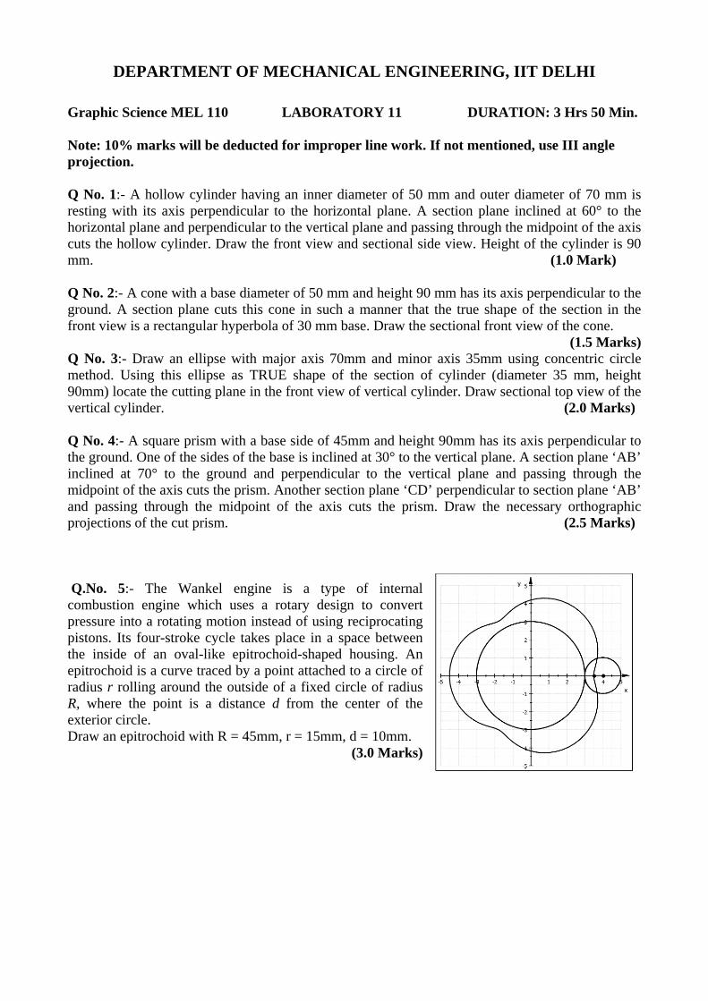
- The Wn engine wnto a rotatins four-strok
of an ovad is a curveolling arounthe point ircle. pitrochoid w
MENT OF
EL 110
ill be deduc
cylinder havperpendiculperpendiculader. Draw th
h a base diaane cuts thigular hyperb
ellipse withellipse as Tting plane in
rism with ae sides of th
he ground acuts the prism
the midpoiprism.
ankel engiwhich uses ng motion inke cycle takal-like epitre traced by and the outsidis a distanc
with R = 45
F MECHA
LABO
cted for imp
ving an innlar to the har to the verhe front vie
ameter of 50is cone in sbola of 30 m
h major axisTRUE shapen the front v
a base side ohe base is inand perpenm. Anotherint of the a
ine is a a rotary d
nstead of uskes place inrochoid-shaa point attacde of a fixece d from
mm, r = 15
ANICAL
ORATORY
proper line
ner diameterhorizontal prtical plane ew and sect
0 mm and hsuch a manmm base. Dr
s 70mm ane of the seview of vert
of 45mm annclined at 30dicular to
r section plaaxis cuts th
type of indesign to csing recipro
n a space beaped housinched to a cied circle of the center
mm, d = 10(3.0 M
ENGINE
Y 11
e work. If n
r of 50 mmlane. A secand passing
tional side v
eight 90 mmner that theraw the sec
nd minor axection of cytical cylinde
nd height 900° to the vethe vertical
ane ‘CD’ pehe prism. D
nternal convert ocating etween ng. An ircle of f radius
of the
0mm. Marks)
EERING,
DURAT
not mention
m and outer ction plane g through thview. Heigh
m has its axe true shapetional front
xis 35mm uylinder (diaer. Draw se
0mm has itsrtical planel plane and
erpendicularDraw the n
IIT DEL
TION: 3 H
ned, use III
diameter oinclined at
he midpointht of the cyl (1.0
xis perpendie of the secview of the
(1using conceameter 35 mctional top (2
s axis perpe. A section d passing tr to section
necessary or (2
HI
rs 50 Min.
I angle
f 70 mm ist 60° to thet of the axislinder is 90Mark)
icular to thection in thee cone. 1.5 Marks)entric circlemm, heightview of the.0 Marks)
endicular toplane ‘AB’
through theplane ‘AB’rthographic.5 Marks)
s e s 0
e e
) e t e
o
e
c

DEPARTMENT OF MECHANICAL ENGINEERING, IIT DELHI
Graphic Science MEL 110 LABORATORY 12 DURATION: 3 Hrs 50 Min. Note: 10% marks will be deducted for improper line work. Use III angle projection and assume any missing dimensions suitably.
Q No.1 A square prism with a base side of 50mm and a height of 80mm stands on the ground with a side of base inclined at 30° to the vertical plane. It has a cylindrical hole of 55 mm diameter drilled through it. The center line of the hole is parallel to both the Horizontal Plane and the Vertical Plane and is 5mm away from center of the axis of the prism towards the Vertical plane. Draw the projections of the prism showing the curves of intersection. (3 marks)
Q No.2 Draw the curves of intersection of the hexagonal and triangular prism as shown in figure 1. (2 marks)
Q No.3 Draw the curves of intersection of the hemisphere intersected by a square prism as shown in figure 2. The axis of the prism is 10 mm due south-east of the centre of the hemisphere. Assume a suitable height of the prism. (2 marks)
Q No.4 Draw the curves of intersection, in the top and the front view, of the cone intersected by a cylinder as shown in figure 3. (Use the PAV in which the cylinder is seen as a circle). Also, draw the auxiliary view of the solid in which the cylinder is visible as a circle. (3 Marks)
Figure 1
Figure 2
Figure 3
DEPARTMENT OF MECHANICAL ENGINEERING, IIT DELHI
Graphic Science MEL 110 LABORATORY 13 DURATION: 3 Hrs 50 Min. Note: 10% marks will be deducted for improper line work.
Q No. 1:- A hexagonal prism, having base with a 30mm side and height 70mm is resting on the ground with a side of the base inclined at 45° to the vertical plane. It is cut by a plane inclined at 45° with the ground and passing through a point 15mm below the top end of the axis. Obtain the development of the lateral surface of the prism. (1.5 marks)+.5
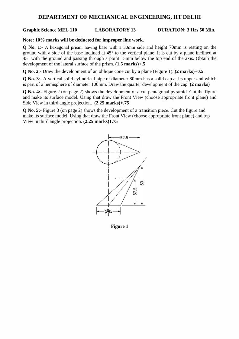
Q No. 2:- Draw the development of an oblique cone cut by a plane (Figure 1). (2 marks)+0.5
Q No. 3:- A vertical solid cylindrical pipe of diameter 80mm has a solid cap at its upper end which is part of a hemisphere of diameter 100mm. Draw the quarter development of the cap. (2 marks)
Q No. 4:- Figure 2 (on page 2) shows the development of a cut pentagonal pyramid. Cut the figure and make its surface model. Using that draw the Front View (choose appropriate front plane) and Side View in third angle projection. (2.25 marks)+.75
Q No. 5:- Figure 3 (on page 2) shows the development of a transition piece. Cut the figure and make its surface model. Using that draw the Front View (choose appropriate front plane) and top View in third angle projection. (2.25 marks)1.75 \
Figure 1
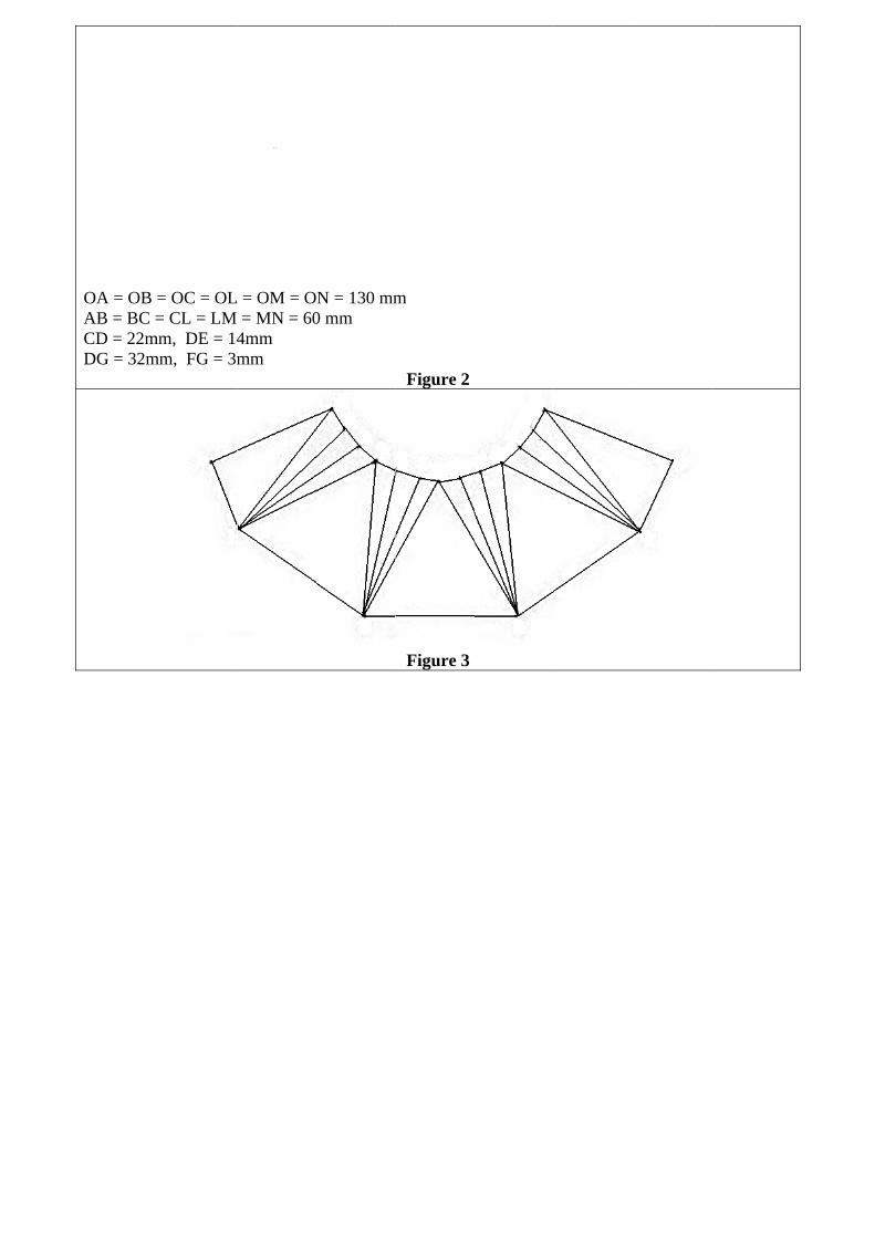
OA = OB =AB = BC =CD = 22mDG = 32m
= OC = OL= CL = LM m, DE = 14
mm, FG = 3m
L = OM = O= MN = 60
4mm mm
N = 130 mm0 mm
m
Figure 2
Figure 3

DEPARTMENT OF MECHANICAL ENGINEERING, IIT DELHI
MEL 110 LABORATORY 14 (to be done in CAGI Lab. Room: III 331) DURATION: 3 Hrs 50 Min. Note: If any dimensions are missing they should be suitably assumed.
Problem 1: Obtain the sectional view of the solid model shown in figure 1. Identify the error in the sectional view generated using Autodesk Inventor. (1.5 marks) Problem 2: The orthographic views of an object are given in figure 2. Make the solid model of the object and obtain the necessary (auxiliary & orthographic) views so as to represent the true shapes of all the features. (2 marks) Problem 3: A cone with base diameter 70mm and half angle 20° rests on the horizontal plane. It is intersected by another cone with base radius 20mm and half angle 10°. The base of the second cone is parallel to the side plane and the axes of the cones intersect at a height of 35mm from the base of the first cone. Also, the base of the second cone is at a distance of 40mm from the axis of the first cone. Assuming any missing dimensions, make a solid model of the solid of intersection and obtain the projections showing the curves of intersection. (2 marks) Problem 4: A square prism with a base side of 40mm and a height of 70mm stands on the ground with a side of base inclined at 30° to the vertical plane. It is completely penetrated by a cylinder having 40mm diameter and 90mm length. The axis of the cylinder is parallel to both the horizontal and the vertical plane and bisects the axis of the prism. Make a solid model of the solid of intersection Obtain the projections showing the curves of intersection. (2 marks) Problem 5: A picture frame 2m wide and 2m high is to be fixed on a wall railing by two straight wires attached to the top corners. The frame is to make an angle of 40° with the wall and the wires are to be fixed to a hook on the wall on the center line of the frame and 1.5 m above the railing. Find the length of the wires and the angle between them. (2.5 marks)
Figure 2
Figure 1