megator - atex instruction manual
TRANSCRIPT

1 of 86
INSTRUCTION BOOK
H TYPE
ATEX Group II Category 3G c T4
MEGATOR LIMITED
HENDON, SUNDERLAND, TYNE & WEAR, SR1 2NQ, ENGLAND
Tel +44 (0) 191 567 5488 Fax +44 (0) 191 567 8512
E-Mail: [email protected] Website: www.megator.co.uk

2 of 86
CONTENTS MEGATOR DECLARATION ....................................................................................................................... 4
WARNINGS .................................................................................................................................................. 5
PUMP DETAILS ........................................................................................................................................... 6
GENERAL ..................................................................................................................................................... 8
TRANSPORT & STORAGE ..................................................................................................................... 8
Transportation guidelines ....................................................................................................................... 8
Pump storage requirements ......................................................................................................................... 9
HOW THE PUMPS WORK ..................................................................................................................... 10
TEMPERATURE RANGE ...................................................................................................................... 11
ATEX PUMP RANGE ............................................................................................................................. 11
INSTALLATION ......................................................................................................................................... 12
LOCATION .............................................................................................................................................. 12
WORKING HEADS OR PRESSURES ................................................................................................... 12
ROTATION AND BRANCHES .............................................................................................................. 13
BALL BEARINGS ................................................................................................................................... 13
ELECTRIC MOTORS ............................................................................................................................. 13
SWITCHGEAR ........................................................................................................................................ 14
PIPING ..................................................................................................................................................... 14
HOSE ....................................................................................................................................................... 14
SUCTION STRAINER ............................................................................................................................ 14
VACUUM LIMITING VALVE ............................................................................................................... 15
BYPASS RELIEF VALVE ...................................................................................................................... 16
BYPASS RELIEF VALVE DATA SHEET (542L) ................................................................................. 17
BYPASS RELIEF VALVE DATA SHEET CONT… (542L) ............................................................. 18
BYPASS RELIEF VALVE DATA SHEET (500L) ................................................................................. 19
BYPASS RELIEF VALVE DATA SHEET CONT… (500L) ............................................................. 20
STARTING AND RUNNING ..................................................................................................................... 21
DRIVE ASSEMBLY – COUPLINGS ..................................................................................................... 21
PRELIMINARY FILLING ...................................................................................................................... 21
FIRST STARTING .................................................................................................................................. 21
REGULATION OF CAPACITY ............................................................................................................. 21
FROST ..................................................................................................................................................... 22
FAILURE TO PRIME .............................................................................................................................. 22
MAINTENANCE ......................................................................................................................................... 23
TIGHTENING TORQUES ...................................................................................................................... 23
REMOVAL AND REASSEMBLY OF SHOES ...................................................................................... 23
ADJUSTMENT OF SHOE CLEARANCE .............................................................................................. 24

3 of 86
GASKETS ................................................................................................................................................ 24
SHAFT SEALS ........................................................................................................................................ 24
REMOVAL AND RE-ASSEMBLY OF ROTOR AND/OR SHAFT SEALS ......................................... 25
H75, H100, H125, H150, H200 ............................................................................................................ 25
H300, H400 .......................................................................................................................................... 25
REMOVAL AND RE-ASSEMBLY OF ROTOR AND/OR SHAFT SEALS Cont.…. .......................... 26
PREMATURE REPLACEMENT OF PORT PLATE OR SHOES ......................................................... 27
INSPECTION INTERVALS .................................................................................................................... 28
Maintenance inspections....................................................................................................................... 28
Routine maintenance ............................................................................................................................ 28
Routine inspections .............................................................................................................................. 28
Three-month inspections ...................................................................................................................... 28
Annual inspections ............................................................................................................................... 28
TROUBLESHOOTING ........................................................................................................................... 29
INTRODUCTION ................................................................................................................................ 29
TROUBLESHOOTING ....................................................................................................................... 29
PREMATURE REPLACEMENT OF PORT PLATE AND / OR SHOES .......................................... 29
NOISE AND VIBRATION .................................................................................................................. 29
PUMP BEARING AND SHAFT SEAL .............................................................................................. 29
PUMP UNIT TROUBLESHOOTING ..................................................................................................... 29
PUMP UNIT TROUBLESHOOTING (CONT`D) .............................................................................. 30
PUMP UNIT TROUBLESHOOTING (CONT`D) .............................................................................. 31
PUMP UNIT TROUBLESHOOTING (CONT`D) .............................................................................. 32
PUMP UNIT TROUBLESHOOTING (CONT`D) .............................................................................. 33
SPARE PARTS LIST ................................................................................................................................... 36
PUMP TYPE H75, H100, H125, H150 AND H200 ............................................................................. 36
SPARE PARTS LIST ................................................................................................................................... 37
PUMP TYPE H300 AND H400 ........................................................................................................... 37
COUPLING .................................................................................................................................................. 38
INSTALLATION ..................................................................................................................................... 38
CERTIFICATE OF CONFORMANCE ................................................................................................... 39
ELECTRICAL MOTOR .............................................................................................................................. 40
MANUAL ................................................................................................................................................ 40
CERTIFICATE OF CONFORMANCE ................................................................................................... 85
DATA SHEETS ....................................................................................................................................... 86

4 of 86
MEGATOR DECLARATION

5 of 86
WARNINGS
Please note this pump runs at a typical noise level of 84 dB(A) – (Megator limited
recommends the use of hearing protection)
Read the instructions thoroughly before use.
Read the instructions of the motor (and generator) before use paying particular attention to
the safety advice.
The equipment must only be installed by competent trained personnel. Do not attempt
installation unless qualified to do so.
This equipment is only to be used for pumping of liquids. Megator Ltd. will not be
responsible for any damage or injury caused by misuse.
The equipment is not to be modified in any way. Megator Ltd. will not be responsible for
any damage or injury caused by unauthorised modifications.
This equipment must be installed in accordance with the latest edition of BS 7671, the IET
wiring regulations and the Pressure Systems Safety Regulations 2000, or any other local
regulations in force.
The equipment is suitable for use in a zone 2 hazardous area. The motor must be selected
and installed in accordance with IEC 60079-14. The pump must be equipotentially bonded
using the terminal provided.
Observe local environmental regulations when disposing of the equipment or its component
parts.
The equipment must only be operated and maintained by competent trained personnel. Do
not attempt repairs unless qualified to do so.
Take care when handling the equipment. It comes packaged so that lifting gear can be used
to prevent injuries due to handling. Ensure that suitable lifting gear is used.
Take care when installing the equipment. The equipment may be top heavy and may
require supports to allow installation to take place.
Do not block or obstruct outlets of relief valves or tamper with the operation of safety
devices.
Ensure that electricity supply is isolated and locked off before removing guards or covers.
Ensure that fluid supply and where applicable, fluid return is isolated and locked off before
removing piping.
6 of 86
PUMP DETAILS
PUMP TYPE: H________
SERIAL NO: _____________
MOTOR TYPE: EXICO
SERIAL NO: _____________
kW RATING: __________ kW
VOLTAGE: ___V/_ph/__Hz.

7 of 86
MEGATOR
TYPE H PUMPS ATEX APPROVED
ATEX Group II Category 3G c T4
OPERATING INSTRUCTIONS
AND
PART LIST
ORDERING SPARE PARTS
To ensure quick supply of spare parts, the following information should
be given:
1. Pump type and serial number, as stamped on the nameplate.
2. Part number and name of part.
MEGATOR LIMITED
Hendon, Sunderland, Tyne & Wear, SR1 2NQ, England.
Tel. + 44 191 5675488 Fax. + 44 191 5678512
E-mail: [email protected]
8 of 86
GENERAL
TRANSPORT & STORAGE
Transportation guidelines
Pump handling
WARNING:
• Make sure that the unit cannot roll or fall over and injure people or damage property.
• These pumps might use carbon or ceramic silicon carbide components. Do not drop the pump
or subject it to shock loads as this can damage the internal ceramic components.
NOTICE:
Use a forklift truck or an overhead crane with sufficient capacity to move the pallet with the pump unit
on top. Failure to do so can result in equipment damage.
Lifting methods
WARNING:
• All lifting must be done in compliance with all applicable regulations/standards.
• Assembled units and their components are heavy. Failure to properly lift and support this
equipment can result in serious physical injury and/or equipment damage. Lift equipment only
at the specifically identified lifting points. Lifting devices such as hoist rings, shackles, slings
and spreaders must be rated, selected, and used for the entire load being lifted.
Use strap webbing only, never use wire rope slings
• Crush hazard. The unit and the components can be heavy. Use proper lifting methods and wear
steel-toed shoes at all times.
• Do not attach sling ropes to shaft ends.
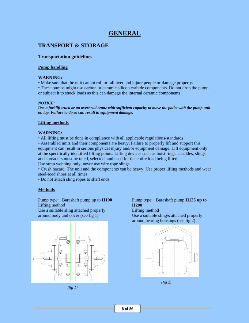
Methods
Pump type: Bareshaft pump up to H100
Lifting method
Use a suitable sling attached properly
around body and cover (see fig 1)
(fig 1)
Pump type: Bareshaft pump H125 up to
H200
Lifting method
Use a suitable sling/s attached properly
around bearing housings (see fig 2)
(fig 2)

9 of 86
Pump type: Bareshaft pump H300 up to
H400
Lifting method
Use a suitable sling/s attached properly
around pump flanges (see fig 3)
Pump type: A base-mounted pump
Lifting method
Use suitable slings attached properly to
lifting eyes on base (see fig 4)
(fig 4)
(fig 3)
Electric Motor
Lifting method
Use suitable slings attached properly to lifting eye/s on motor (see Motor manufacturers
manual)
Pump storage requirements
Storage requirements depend on the amount of time that you store the unit. The normal
packaging is designed only to protect the unit during shipping.
Length of time in storage Storage requirements
Upon receipt/short-term (less than six months) • Store in a covered and dry location.
• Store the unit free from dirt and vibrations.
Long-term (more than six months) • Store in a covered and dry location.
• Store the unit free from heat, dirt, and vibrations.
• Loosen cover and rotate the shaft by hand ¼
turn at least every six months.

10 of 86
HOW THE PUMPS WORK
Fig. 6: Working principle of MEGATOR sliding-shoe pump
The pumping action is derived from the rotation of three or more eccentric discs, each of which
fits closely into a displacement chamber or shoe of plastic material lined with synthetic rubber.
The eccentric movement of each disc comprises horizontal and vertical components; the
horizontal motion provides the displacement, the disc reciprocating in the shoe like a piston in a
cylinder, while the vertical motion controls the entry and discharge of the liquid.
As soon as the pump starts, it creates a hydraulic pressure difference, which holds the shoes in
close contact with a flat port plate forming the division between the suction and delivery sides
of the pump. The plate has ports opposite each shoe leading respectively from the suction
branch into the discharge side of the pump. On the suction stroke, the liquid passes down
through the main cover and is drawn into the shoes through the suction ports in the plate. On
the discharge stroke, the liquid is displaced from the shoes through the discharge ports. It then
passes down through the main cover into the bottom of the body before flowing through another
passage in the main cover to the discharge branch. This arrangement helps to scavenge the
bottom of the body and prevent the accumulation of solids.
Fig. 6 illustrates the working cycle in a single shoe. Although the displacement in each shoe is
intermittent, the combined effect is a smooth continuous flow and an even turning moment.
T h e w o rk in g p r in c ip le s o f th e M e g a to r s l id in g -s h o e p u m p .
S u c tio n s tro k e D is c h a rg e s tro k e

11 of 86
TEMPERATURE RANGE
Up to 38oC normal listed capacity can be obtained. Above this temperature the capacity
progressively decreases as indicated in the table below. 75oC is the maximum fluid temperature
allowable.
ATEX RANGE OF PUMPS ONLY
Total Head up to 4.5 bar Pumping temperature up to 38oC Capacity reduction 0%
Total Head up to 4.5 bar Pumping temperature between 39oC and 75oC Capacity reduction 5%
Total Head from 4.5 bar to 7.5
bar
Pumping temperature up to 38oC Capacity reduction 0%
Total Head from 4.5 bar to 7.5
bar
Pumping temperature between 39oC and 50oC Capacity reduction 5%
Total Head from 4.5 bar to 7.5
bar
Pumping temperature between 51oC and 60oC Capacity reduction 10%
Total Head from 4.5 bar to 7.5
bar
Pumping temperature between 61oC and 75oC Capacity reduction 20%
ATEX PUMP RANGE
rpm Max. flow m3/hr total Suction lift Suction lift Suction lift
min/max kw min/max head @75cSt @1000cSt @2500cSt
H75 atex 960/1440 1.1 0.75/1.25 7.5 bar 7 6.1 n/a
H100 atex 720/960/1440 2.2 1.5/2/2.5 7.5 bar 8.2 6.1 5.2
H125 atex 720/960 4 2.5/3.5 7.5 bar 8.2 6.1 5.2
H150 atex 720/960 5.5 5.5/7.5 7.5 bar 8.2 6.1 5.2
H200 atex 720/960 7.5 10/13.5 7.5 bar 7.5 6.1 5.2
H300 atex 720/960 15 16.5/22.5 7.5 bar 7.5 5.4 5.2
H400 atex 720/960 30 33/45 7.5 bar 7.5 5.4 5.2

12 of 86
INSTALLATION
LOCATION Choose an accessible position with ample space for dismantling and maintenance, and in
particular see that there is room for removing the main cover or covers and shoes and inspecting
the interior. See that the pump can be conveniently drained and filled. Preferably raise it above
floor level to give easier access and so that it can be drained into a receptacle.
WORKING HEADS OR PRESSURES The maximum continuous total head from all causes and the maximum total suction lift from all
causes are as given in the table below. The suction lifts are applicable to maximum listed
speeds and can be exceeded at lower speeds.
Damage will be caused by excessive total heads or suction lifts, and in case of any doubt they
should be checked by pressure and vacuum gauges. The most likely causes of excessive head
or suction lift are: -
(1) Static head (vertical height from surface of liquid on suction side to surface of liquid on
delivery side) too great.
(2) Excessive losses in piping and fittings, due to too small diameter, sharp elbows,
restrictive fittings, etc. See under Piping (Page 14)
(3) Obstruction, due to solids, blocked or buried strainer, flattening of suction, or internal
damage to hose creating a flap which blocks the bore when pump is running.
For efficient operation, the pump should always operate against a total head of not less than 10
feet (3 metres), to ensure effective seating of the shoes in the port plate.

13 of 86
ROTATION AND BRANCHES As indicated by the arrows on the pump, the suction branch is at the right-hand end of the pump
and the delivery at the left-hand end, when facing the front of the pump. The standard assembly
is with the drive at the left-hand (delivery) end.
The direction of rotation of the pump is with top of pulley or coupling moving towards the
front. This means that, with standard assembly, the motor must be wired for “clockwise
rotation facing driving end of motor” in the case of belt-driven sets and “anti-clockwise facing
driving end of motor” in the case of direct-coupled sets. Before testing the rotation of newly
wired set, make sure that the pump is filled with liquid.
See under Starting and Running (Page 21).
The rotation of three-phase A.C. motors can be reversed by changing over any two of the three
mains wires. Single-phase and D.C. motors are reversed by changing the connections on the
motor. There is generally an instruction diagram inside the terminal box.
The pump can be assembled, if more convenient, with the drive at the suction end. The above
instructions for rotation of prime mover are then reversed.
BALL BEARINGS All H pumps except H300 and H400 are fitted with sealed ball bearings, which are lubricated
for life in the factory and have no provision for further lubrication. The bearings of H300 and
H400 pumps are enclosed in housings with shaft seals and nipples for grease-gun lubrication.
The inner ring of the bearing is locked on the shaft by an eccentric locking collar, with a socket
screw in the collar for additional security. The removal and reassembly of the bearings is
described under Removal and Re-Assembly of Rotor (Page 25).
ELECTRIC MOTORS
See manufacturers manual (Page 40)
14 of 86
SWITCHGEAR
Every electrically driven pump must be fitted with a starter with suitable overload releases. The
releases should be set to the full load current of the motor, unless the starter manufacturer
instructs otherwise. Adjustable time lags should be set to the maximum. Starters should be of
direct-on-line type rated for use with motors having a starting torque equivalent to 150% full
load torque, and incorporate single-phase prevention. Fuses should be of the cartridge type and
rated to the maker’s recommendation to carry the starting currents (3 to 5 times full load current
in the case of single-phase motors and 6 to 8 times in the case of three –phase motors started
direct-on-line).
PIPING
The piping should be as short and direct as possible, easy bends or round elbows being used and
sharp elbows and tees avoided. The size of pipe should not be smaller than the pump branches
and for long pipes should generally be larger. Unless the pipe run is very simple, the actual pipe
losses should be estimated, so as to check the total head on the pump, the advice and assistance
of Megator engineers being sought if required. It is quite common for the pipe losses to be
greater than the static head. The piping must be accurately cut and fitted, so that it can be
connected up to the pump branches without putting and strain on the pump or on the pipe joints.
Particular care must be taken to make the joints in the suction line absolutely tight, in order to
avoid loss of capacity or difficulty in priming due to air leaks.
HOSE Suction hose requires wire reinforcement to prevent it from collapsing under atmospheric
pressure. This reinforcement should be completely embedded in the material of the hose
(forming “smooth bore” hose) or, failing this, should be “semi-embedded”, that is, completely
covered but leaving the inside of the hose somewhat corrugated. “Internally armoured” hose
should not be used, as the wire greatly increases resistance to flow and encourages clogging.
Smooth bore suction hose is generally suitable for low-pressure delivery also. Externally
armoured delivery hose should be avoided, as good quality hose itself resists external wear
satisfactorily, and the armouring distorts and restricts the hose if accidentally crushed. Hose
must be of a suitable type to take the fittings, or obtained in the lengths in which it is to be used
with plain moulded ends.
WARNING – Ensure hose is suitable for fluid, pressure, temp, and location
SUCTION STRAINER The suction pipe must be fitted with a strainer of ample size, with holes not exceeding 3/16 in.
(5mm) diameter. The total area of the holes should be about three times the sectional area of the
suction pipe. The Megator pump primes itself so easily that there is generally no point in fitting
a foot-valve, which merely adds to the pipe losses.
A Dolphin Strainer is strongly recommended. This draws from just under the surface, so avoiding
abrasive matter and saving wear. Even under “snore” conditions and where there is insufficient
water to float it, the Dolphin Strainer reduces to a minimum the risk of the suction becoming
choked or buried.

15 of 86
VACUUM LIMITING VALVE
The Vacuum limiting valve is a simple mechanical
device for eliminating pump cavitation when the
pump is running with a choked or closed suction
line, it will also reduce the starting torque of the
pump, especially on the large L and H300 to 400
pumps when working with high suction lifts.
Assembly of Megator Vacuum limiting
valve (Dimensions in Inches)
Sectional arrangement of Megator
Vacuum limiting valve

16 of 86
BYPASS RELIEF VALVE A bypass relief valve, that is to say, a relief valve discharging back to the suction side of the
pump, is a neat and convenient arrangement for many applications. It has the disadvantage,
however, that, if it leaks or is prevented from seating by foreign matter, it forms a connection
from the discharge back to the suction and may prevent the pump from priming. It may also
cause overheating if operated continuously for any length of time, as the same small volume of
liquid is continuously recirculated. The ordinary relief valve, discharging to atmosphere or
piped back to the source of supply, avoids these disadvantages and, as a relief valve is most
commonly fitted to protect the pump against faulty operation, it is an advantage for the
discharge to be visible.
R E L IE F V A L V E A S S E M B L Y
(P L A N V IE W ) (P L A N V IE W )
R E L IE F V A L V E A S S E M B L YB Y -P A S S
17 of 86
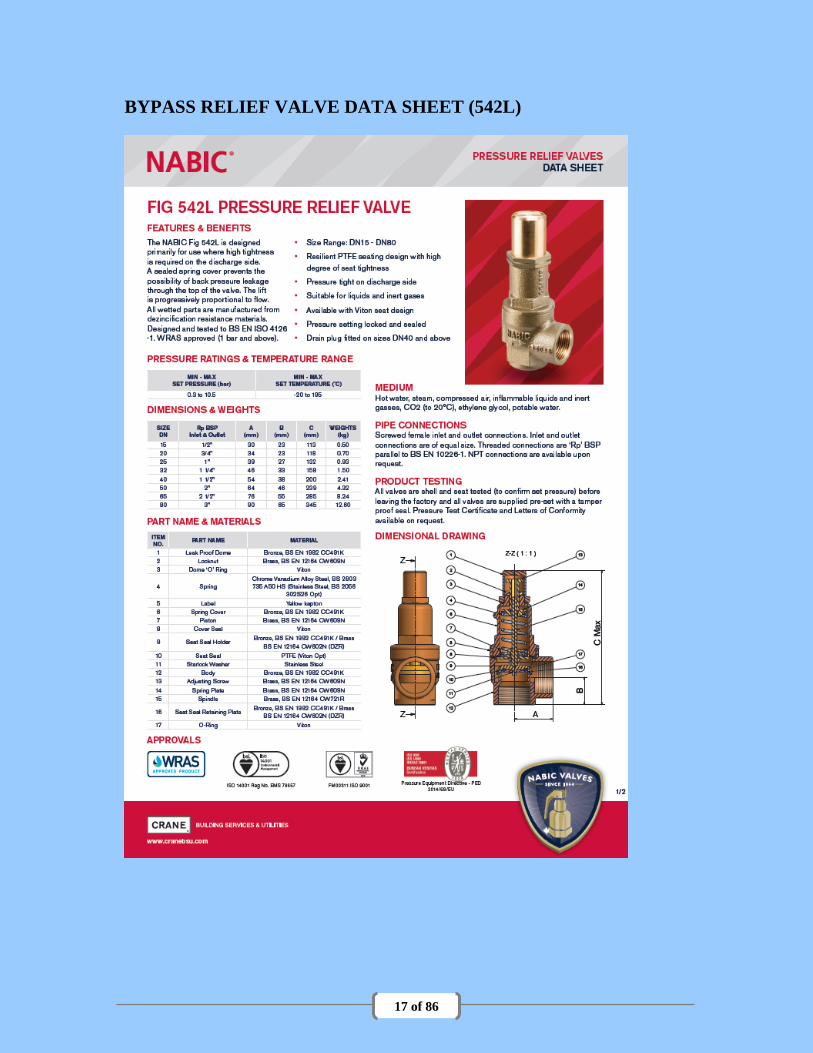
BYPASS RELIEF VALVE DATA SHEET (542L)

18 of 86
BYPASS RELIEF VALVE DATA SHEET CONT… (542L)
19 of 86
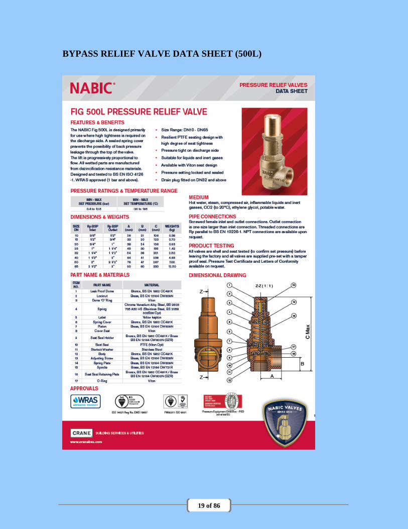
BYPASS RELIEF VALVE DATA SHEET (500L)

20 of 86
BYPASS RELIEF VALVE DATA SHEET CONT… (500L)

21 of 86
STARTING AND RUNNING
DRIVE ASSEMBLY – COUPLINGS
Fenaflex ATEX coupling
Installation and replacement of the flexible tyre can be carried out quickly without disturbing
the coupled shafts even in inaccessible installations. The taper lock flanges, by their versatile
design can always be positioned correctly in order that the desired axial distance between
flanges is obtained to alleviate possible axial reaction. The elastomeric tyre is highly flexible,
which gives excellent shock absorption and smooth running.
PRELIMINARY FILLING
The pump must NEVER be run, even for a few revolutions, in a dry condition.
It should be fitted with water, or with the liquid that is to be pumped, as soon as it is installed
and before the motor is wired. The liquid is essential for lubrication. It also acts as a sealing
medium and the priming may be affected if the pump is only partially filled. Roughening or
gouging out of the ends of the shoe cavity in the path of the rotor is proof of dry running.
This filling is only necessary on first starting up or after the pump has been drained or has been
standing for some weeks, as the pump is constructed so that it normally retains sufficient liquid
when standing. There is not, of course, any need to fill the suction piping.
No harm will result if the pump exhausts the supply of liquid and is left for a considerable time
with a dry suction and therefore pumping air. Megator pumps do not require a bypass to deal
with such conditions.
FIRST STARTING Before first starting up after installation or overhaul, the pump should be turned round by hand,
after filling, to make sure that everything is clear, and, in the case of newly wired motors, the
direction of rotation should then be checked. The pump is always somewhat stiff to turn at the
start, owing to the nature of the rubber surfaces of the shoes, but when it is running the surfaces
are lubricated by a film of liquid and the pump becomes quite free.
REGULATION OF CAPACITY If it is desired to reduce the capacity of the pump, this can be done by reducing the speed or by
bypassing a portion of the output back to the suction. On no account attempt to reduce the flow
by throttling with a valve, as this merely increases the pressure on the pump and may result in a
burst or damaged pump or an overloaded prime mover.

22 of 86
FROST If the pump is left standing in frosty weather, drain it by means of the drain plug in the main
cover. Remove the filler plug at the same time to draw attention to the need for filling the pump
again before starting. An oil-immersed, thermostatically-controlled heater is available as an
optional extra for all H pumps.
FAILURE TO PRIME
See troubleshooting. (Page 29)
NOTE: WHEN PUMPING A HIGH VISCOSITY MEDIUM, THE PUMP SPEED MUST
BE REDUCED ACCORDING TO THE MATERIAL’S VISCOSITY TO PREVENT
CAVITATION.

23 of 86
MAINTENANCE
TIGHTENING TORQUES
Torque values for fastenings on Megator Pumps Unit value: Nm
No.
Main
Cover
Bearing
Housing
Port
Plate
End
Cover
Blank
Flange
Holding
Down
Seal
Plate
Dismantling
Arm
Bearing
Cover
Pump
Material
H75 35 35 20 20 32 35 N/A N/A 20 CI
H100 35 35 20 20 35 35 N/A N/A 20 CI
H125 35 35 20 20 35 35 N/A N/A 20 CI
H150 40 40 25 20 35 35 N/A N/A 20 CI
H200 50 45 25 20 35 35 N/A N/A 20 CI
H300 70 40 35 30 N/A 70 20 30 35 CI
H400 70 40 35 30 N/A 70 20 30 35 CI
REMOVAL AND REASSEMBLY OF SHOES First drain the pump by means of the drain plug in the main cover, at the same time removing
the filler plug ready for refilling before starting up again. Remove the main cover or covers and
the shoes can then be taken out.
Although the shoes are interchangeable and will work either way up, they should be marked for
identification before they are taken out and put back in the same position, and the same way up,
so as to take advantage of the bedding-down that takes place when running.
The shoes, which are lined with synthetic rubber, are initially a push fit on the rotor discs. They
will still give a good performance when comparatively loose, but should be replaced if there is
appreciable clearance on the disc diameter. If a new shoe is loose on the rotor disc, it indicates
wear of the rotor.
When reassembling, make sure that the cover gaskets are clean and undamaged. If the shoes are
a loose fit and tend to fall off the discs, they can be rested on the bottom edge of the opening in
the body, leaning against the discs, and when the cover is put on it will push them into position.

24 of 86
ADJUSTMENT OF SHOE CLEARANCE There is only a small clearance between the shaft and the inner edge of the shoes, which are
thus kept close up to the port plate. As soon as the pump starts working, the shoes are held
tightly against the port plate by the pressure created by the pumping action. If wear occurs
between the port plate and the bases of the shoes, it is automatically taken up by the pressure. A
condition of wear may eventually be reached, however, when the clearance is so increased that
the shoes have difficulty in building up the requisite pressure to start with. The first symptoms
of this condition are likely to be sluggishness in priming or reduced or irregular flow due to one
at least of the shoes not being properly in action.
Also, where the pump is operating with a suction lift and discharging through a delivery pipe
open to atmosphere, there is a tendency for the water to siphon out and partially empty the body
when the pump stops. With normal shoe clearance the pump will pick up and prime under
these conditions, but if shoe clearance becomes excessive, the pump may fail to prime.
To deal with the above conditions, provision is made for taking up the clearance very simply by
removing one of the main cover gaskets. Care must be taken however that the clearance is not
eliminated altogether and the shoes actually gripped between the port plate and the shaft.
It is generally possible to feel that there is a clearance by turning the pump backwards and
forwards by hand, as there is a small amount of idle motion before the shoes are checked by the
port plate and the movement becomes stiffer due to the rotor turning inside them. If it is
impracticable to feel the clearance in this way, it is quite a simple matter to check it by
measuring the parts concerned.
GASKETS
If any gaskets are damaged in dismantling, they must be replaced with new ones. It is essential
that the material of end and port plate gaskets should be 1/32 in. (0.75mm) thick, so as to
preserve the correct clearances in the pump assembly. It is best to obtain a few sets of spare
gaskets from the pump makers and keep them in stock.
SHAFT SEALS
The shaft seals are self-adjusting and normally operate without any leakage or drip and require
no attention. Although the normal life of the seals is very long, it is advisable to keep a spare
set in stock. Any sign of leakage at this point should receive immediate attention.
When handling the seals, the utmost care must be taken to protect the face ring and seat from
damage or distortion and to keep the mating surfaces absolutely clean and dry. On no account
put oil on them. New parts should be kept in their wrappings until the moment of fitting.
The method of access to the seals is described under Removal and re-assembly of rotor (see
below)

25 of 86
REMOVAL AND RE-ASSEMBLY OF ROTOR AND/OR SHAFT
SEALS H75, H100, H125, H150, H200
Remove main cover and shoes as previously described. Remove pulley or coupling and bearing
covers. Slacken socket screws in bearing locking collars and, using the socket screw key as a
bar, undo the locking collars by turning them in direction opposite to the rotation of the pump.
If a collar is too stiff to undo with the key, it can be freed by a sharp blow with hammer and pin
punch in the hole provided. It is important to see that the collar does not suddenly slacken and
rotate far enough to lock in the opposite direction, as further hammer blows would then only
increase the locking effect.
If a small burr has been raised on the shaft by the socket screw, it should be removed before
starting to remove the bearing housing.
One of the bearing housings should be removed with the bearing in it, using the forcing screws
and taking care not to damage or soil the working faces with the shaft seal. The rotor can then
be withdrawn at the same end, leaving the other bearing housing and bearing in place.
To reassemble the pump, first mount the seals on the rotor shaft and the seal seats in their
mounting rings in the recesses in the bearing housings, taking care not to damage or soil the
working surfaces of the face rings and seats or to get oil or other liquid on them. Before
mounting the seals on the shaft, smear the shaft with a little light grease or heavy oil, which will
allow the oil-resisting synthetic rubber bellows to slide easily into the correct position when all
the parts are bolted up. The bellows should not be compressed, but left in the normal extended
condition, and when the assembly is completed the parts of the seal will take up their correct
positions. Then put the bearings into the bearing housings, fit one bearing housing, with
bearing, to the body and insert the rotor shaft into that bearing, again taking care to protect the
working faces of the seals. Then fit the other bearing housing to the body, threading the bearing
on to the rotor shaft.
Locate outer face of drive-end bearing collar flush with shoulder on shaft (see Fig. 7) and lock
out by turning in the direction of rotation and tightening the socket screw. After locking, make
sure that the face of the collar is still flush with the shoulder. Fit drive-end-bearing cover,
which locates the shaft axially. Locate outer face of outer end bearing locking collar flush with
end of shaft and lock by turning in direction of rotation and tightening socket screw. Fit bearing
cover and pulley or coupling.
H300, H400
These larger pumps have sleeves in the end covers, in which the seal collars on the rotor rest
before the ball bearings are fitted or after they have been removed. This facilitates both
dismantling and assembly of the pump and permits attention to the seals after removing the ball
bearings, without disturbing the rotor, main covers or shoes.

26 of 86
REMOVAL AND RE-ASSEMBLY OF ROTOR AND/OR SHAFT
SEALS Cont.….
To remove the ball bearings, take off pulley or coupling and bearing covers. Slacken
socket screws in bearing locking collars and, using the socket screw key as a bar, undo
the locking collars by turning them in direction opposite to the rotation of the pump. If
a collar is too stiff to undo with the key, it can be freed by a sharp blow with a hammer
and pin punch in the hole provided. It is important to see that the collar does not
suddenly slacken and rotate far enough to lock in the opposite direction, as further
hammer blows would then only increase the locking effect. If a small burr has been
raised on the shaft by the socket screw, it should be removed before starting to remove
the bearing housing. The two bearing housings can then be removed with the bearings
in them, leaving the rotor resting in the end covers.
The seal plates, with the seal seats in them, can next be removed, after which the rest of the seal
assemblies can be pulled off the shaft using forcing screws screwed into the backing plates. A
little oil or grease on the shaft makes the synthetic bellows slide off more easily.
If the rotor is to be removed, the main cover has to be taken off and the shoes extracted. One
end cover should be removed, using the forcing screws, and the rotor slid out.
To reassemble the pump, enter seal collar of rotor into the end cover already secured to the
body, raise the free end of the rotor and thread the other end cover over it. Then bolt this end
cover up to the body. See that the end cover gaskets are undamaged. The seals with stainless
steel backing plates should then be fitted on the shaft, a little light grease or heavy oil being
used to make the bellows slide easily along the shaft. Fit the seal seats into their mounting rings
into the seal plates and fasten them up to the end covers. When handling the seals, the
greatest care must be taken not to damage or soil the mating surfaces of the face ring and
seat or to get oil or other liquid on them. Insert the ball bearings into their housings and
thread them on to the shaft. In the case of the H300 and H400 pumps, the bearing housing must
be filled about two-thirds full of water-repellent lime-based ball bearing grease (some being
worked well into the ball cage) and the plates and seal rings fitted. The bearing of the L300 and
L400 pumps are sealed and lubricated for life in the factory. Locate outer face of drive-end
bearing cover, which locates the shaft axially. Locate outer face of outer end bearing locking
collar flush with end of shaft and lock by turning in direction of rotation and tightening socket
screw. Fit bearing cover and pulley or coupling.
27 of 86
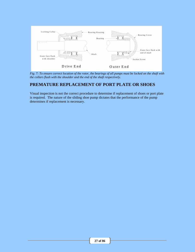
Fig. 7: To ensure correct location of the rotor, the bearings of all pumps must be locked on the shaft with
the collars flush with the shoulder and the end of the shaft respectively.
PREMATURE REPLACEMENT OF PORT PLATE OR SHOES Visual inspection is not the correct procedure to determine if replacement of shoes or port plate
is required. The nature of the sliding shoe pump dictates that the performance of the pump
determines if replacement is necessary.
D riv e E n d O u te r E n d
B e a r in g H o u s in g
B e a r in g C o v e r
O u te r fa c e f lu s h w ith
e n d o f s h a f t
L o c k in g C o lla r
O u te r fa c e f lu s h
w ith s h o u ld e r S o c k e t S c re w
B e a r in g
S h a f t

28 of 86
INSPECTION INTERVALS
Maintenance inspections A maintenance schedule includes these
types of inspections:
• Routine maintenance
• Routine inspections
• Three-month inspections
• Annual inspections
Shorten the inspection intervals
appropriately if the pumped fluid is
abrasive or corrosive
Routine maintenance Perform these tasks whenever you perform
routine maintenance:
• Inspect shoes for wear
• Inspect port plate for wear
• Inspect rotor for wear
Routine inspections Perform these tasks whenever you check
the pump during routine inspections:
• Check for unusual noise,
vibration, and bearing
temperatures.
• Check the pump and piping for
leaks.
• Ensure that there are no leaks
from the mechanical seal.
Three-month inspections Perform these tasks every three months:
• Check that the foundation and
the hold-down bolts are tight.
• Check the fluid level in the
pump, if the pump has been left
idle, and refill as required.
• Grease bearings (H300 & H400
pump only)
• Grease more often if there are
adverse atmospheric or other
conditions that might
contaminate or break down the
grease
Annual inspections Perform these inspections one time each
year:
• Check the pump capacity.
• Check the pump pressure.
• Check pump suction.
• Check the pump power.
If the pump performance does not satisfy your process requirements, and the process requirements have
not changed, then perform these steps:
1. Disassemble the pump.
2. Inspect it.
NOTE: CORRECT MAINTENANCE IS REQUIRED TO AVIOD POTENTIAL
HAZARDS WHICH GIVE A RISK OF EXPLOSION
The responsibility for compliance with maintenance instructions is with the plant operator.
To avoid potential explosion hazards during maintenance, the tools, cleaning and painting materials used
must not give rise to sparking or adversely affect the ambient conditions. Where there is a risk from such
tools or materials; maintenance must be conducted in a safe area.

29 of 86
TROUBLESHOOTING
INTRODUCTION
The pump has a single function: to pump liquid within its constraint. The following troubleshooting
techniques are designed to determine the nature and location of any difficulty the pump may incur in
obtaining its duty and what action to take.
TROUBLESHOOTING
Use the table shown as a guide to troubleshooting for the pump unit.
PREMATURE REPLACEMENT OF PORT PLATE AND / OR SHOES
Visual inspection is not the correct procedure to determine if replacement of shoes or port plate is
required. The nature of the sliding shoe pump dictates that the performance of the pump determines if
replacement is necessary.
NOISE AND VIBRATION
During normal operation, the pump unit may be noisy and vibrate. Noise and vibration are not criteria for
shoe or port plate replacement. To determine if replacement is needed the performance criterion should
be used.
PUMP BEARING AND SHAFT SEAL
Do not repair bearings or shaft seals. They will require replacement. A shaft seal failure will not
necessarily mean that bearing replacement is required. If leaking fluid is discovered during operational
maintenance, this will indicate that the shaft seal is scored or broken. Replace seals as necessary. During
the inspection of the shaft seals or normal operation of the pump, the bearings are found to be noisy or run
rough, replace bearings as necessary.
PUMP UNIT TROUBLESHOOTING
Motor will not start
Electrical supply – Phase
Failure due to blown fuse.
Trace and remove fault- Renew
Blown fuse.
Electrical supply-Low voltage.
Check voltage at motor terminals,
if voltage is too low use higher
voltage on transformer terminals or
switch off offending heavy load or
refer to the supply authority
Motor control equipment –
Circuit breaker tripped in control
enclosure.
Reset after determining reason breaker
tripped.

30 of 86
PUMP UNIT TROUBLESHOOTING (CONT`D)
Motor will not start.
Cont`d.
Motor overload tripped.
a). Check overload is set to Full
Load Current as stated on the motor
Name plate.
b). If current exceeds the Full Load
Current shown on the motor name-plate,
reduce load or replace with larger
motor.
c). If mechanical defects of pump or
motor exist which may cause binding
and rubbing of rotating elements i.e.
Failed bearings, pump shaft seals or
bent rotor, replace offending parts.
d). Primary cause of overloading is
excessive head pressure.
Ensure isolating valves are open and
discharge piping unobstructed.
Short circuit
Check motor insulation resistance to
ground. Check resistances between
phases. If stator short circuits, replace
motor.
Motor overheats
Motor is overloaded,
Operating at an improper
voltage or short circuits.
See above “Motor will not start”.
Motor ventilation paths
obstructed.
Thoroughly clean motor ventilation
paths and clear any obstruction.
Insufficient cooling medium.
Check room temperature.
Temperature should not exceed the
ambient temperature plus the rated
temperature rise. Reduce ambient
temperature.
Winding fault developing.
a). Check with ammeter for balanced
Phase currents. Clean and dry windings.

31 of 86
PUMP UNIT TROUBLESHOOTING (CONT`D)
Motor overheats.
Cont`d.
Winding fault developing.
b). If problem persists, replace motor
Vibration.
Misalignment of drive.
Re-align drive.
Loose or missing anchor screws.
Check pump and motor holding down
screws for tightness.
Failure to pump liquid.
Pump body not primed or
partially primed.
Check fluid level in pump.
Check shaft seals for leaks.
Further information available from
manufacturer if required.
Wrong rotation.
The rotation of a three-phase A.C motor
can be reversed by changing over any
two of the three phases at the motor
terminals. Single phase motors are
reversed by changing the connections on
the motor.
Suction and/or discharge valves
closed.
Open suction and/or discharge valve in
accordance with system operating
instructions.
Suction strainer clogged.
Clean strainer. If simplex strainer is
used, shut down system to clean. If a
duplex strainer, switch flow through
other strainer basket to clean original
basket.
Obstructed pump delivery or
suction chamber and main cover
ducts.
Check and remove obstruction.
Further information available from
Manufacturer if required.
Air getting into suction line or
pump suction chamber. Damage
to main cover gaskets and if
fitted, vacuum limiting valve
spring clogged or broken, dam-
aged seal ring or fibre washer.
Damaged `O` ring on Relief
valve spindle
a). Hydrostatically check suction piping
and valves.
b). Check and clean vacuum limiting
valve assembly.
c). Inspect `O` ring on relief valve
spindle. This only applies with the
B.P.R.V. arrangement. Further
information available from manufacturer
if required.

32 of 86
PUMP UNIT TROUBLESHOOTING (CONT`D)
Failure to pump liquid
Cont`d.
Excessive shoe clearance
between shaft and port plate.
(Worn port plate and/or shoes).
Remove one of the front cover gaskets.
This will bring the clearance between
the shoe face and port plate to an
acceptable tolerance and will provide
increased capacity. For the `H400`
pumps also, remove one of the back
cover gaskets.
Damaged shoes and/or port plate.
Replace shoes and/or port plate and
main cover gaskets.
Damaged rotor.
Check shaft and eccentric discs for
wear.
Liquid discharging or
recirculating back to suction
through relief valve.
a). Check pump discharge isolating
valve is open.
b). Check and clear discharge piping
and valves of any obstructions.
c). Check that the relief valve spring is
set for the required system pressure.
(8.6 bar for `H` range of pumps.)
d). Broken relief valve spring.
Capacity, discharge
pressure or suction lift
reduced below
application requirements.
Suction valves or piping
obstructed.
Check and clear obstruction.
Suction strainer clogged.
Clean strainer.
Air entering suction line through
damaged piping, gaskets or
valves
a). Hydrostatically check piping and
valves for leaks including vacuum
limiting valve.
b). Check for damaged or missing `O`
ring on relief valve spindle. (This only
applies when a by-pass relief valve
assembly is fitted).
Pump obstructed with foreign
objects.
Open pump unit and clear obstruction.
Worn shoes and/or port plate.
See excessive shoe clearance above.
33 of 86
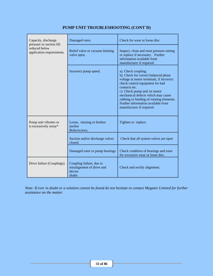
PUMP UNIT TROUBLESHOOTING (CONT`D)
Capacity, discharge
pressure or suction lift
reduced below
application requirements.
Damaged rotor.
Check for wear or loose disc.
Relief valve or vacuum limiting
valve open.
Inspect, clean and reset pressure setting
or replace if necessary. Further
information available from
manufacturer if required.
Incorrect pump speed.
a). Check coupling.
b). Check for correct balanced phase
voltage at motor terminals, if incorrect
check control equipment for bad
contacts etc.
c). Check pump and /or motor
mechanical defects which may cause
rubbing or binding of rotating elements.
Further information available from
manufacturer if required.
Pump unit vibrates or
is excessively noisy*
Loose, missing or broken
anchor
Bolts/screws.
Tighten or replace
Suction and/or discharge valves
closed.
Check that all system valves are open
Damaged rotor or pump bearings
Check condition of bearings and rotor
for excessive wear or loose disc.
Drive failure (Couplings).
Coupling failure, due to
misalignment of drive and
driven
shafts
Check and rectify alignment.
Note: If ever in doubt or a solution cannot be found do not hesitate to contact Megator Limited for further
assistance on the matter.

34 of 86
Fig 8: Exploded view of three-shoe pump, showing principal component parts

35 of 86
Fig. 9: Bearing and seal assembly of H75, H100,
H125, H150 and H200 pumps
Fig. 10: Bearing and seal assembly of H300,
H400.
1 8
9
3 6
3 8
1 2 X3 41 7 X
2 5 X
3 9
2 2 X
2 6 X
1 52 8 X
3 7
4
2 0
3 5
3 1

36 of 86
SPARE PARTS LIST
PUMP TYPE H75, H100, H125, H150 AND H200
No. No.
Drg. per per
ref. Description H75 H100 H125 pump H150 H200 pump
1 Body 5101 5301 5501 1 5701 5901 1
2 Main cover 5002 5302 5502 1 5702 5902 1
3 Body blank flange 5003 5003 5403 2 5603 5603 2
4 * Bearing housing 5404 5604 5804 2 5704 5904 2
5 Port plate 5005 5205 5405 1 5605 5805 1
6 D/E bearing cover 5406 5606 5806 1 5706 5906 1
7 O/E bearing cover 5407 5607 5807 1 5707 5907 1
8 Rotor 5131 5331 5531 1 5731 5931 1
9 Bearing 5447 5647 5847 2 5747 5947 2
10 Front stud 5048 5348 5548 8 5748 5948 10
11 End stud 5050 5650 5650 8 5950 5950 8
12 Blank flange stud 5050 5050 5050 4 5650 5650 4
13 Shoe 5161 5361 5561 3 5761 5961 3
14 Main cover gasket 5070 5270 5470 2 5670 5870 2
15 Bearing housing gasket 5474 5674 5874 2 5774 5974 2
16 Port plate gasket 5071 5271 5471 1 5671 5871 1
17 Blank flange gasket 5073 5073 5473 2 5673 5673 2
18 * Shaft seal 5479 5679 5879 2 5779 5979 2
19 Port plate screw 3403 3404 3405 3 3406 3407 3
20 Bearing cover screw 3401 3401 3401 4 3402 3402 4
21 Main cover dowel 3411 3411 3412 2 3413 3413 2
22 Bearing housing dowel 3411 3411 3411 4 3411 3411 4
23 Filler plug 1055B 1055B 1055B 1 1262B 1262B 1
24 Filler plug washer 1056 1056 1056 1 1263 1263 1
25 Drain plug 1260B 1260B 1051B 1 1051B 1055B 1
26 Drain plug washer 1261 1261 1078 1 1078 1056 1
27 Body nut 3408 3409 3409 16 3410 3410 18
28 Blank flange nut 3408 3408 3408 4 3409 3409 4
29 Shaft key 1728 1728 1089 1 1729 1729 1
30 Gauge plug 1052 1052 1052 2 1052 1052 2
31 Forcing screw 3708 3708 3708 2 3708 3709 2
*When ordering spare being housings or seals for American-built pumps, identifiable by Megator Corporation
nameplate, add suffix USA to the part number.
NOTE: When ordering pulleys, quote outside diameter, number of grooves and shaft diameter.

37 of 86
SPARE PARTS LIST
PUMP TYPE H300 AND H400
no. no.
Drg. Per per ref. Description H300 Pump H400 pump
1 Body 6001 1 6201 1
2 Front cover 6002 1 6002 1 3 Back cover -- -- 6202 1
4 Bearing housing 6104 2 6104 2
5 Port plate 6105F 1 6105F 2
6 D/E bearing cover 6106 1 6106 1
7 O/E bearing cover 6107 1 6107 1
8 Rotor 6131F 1 6331F 1 9 Bearing 6147 2 6147 2
10 Front stud 6048 10 6048 20
11 End stud 6050 8 6050 8
12 End cover 6012 2 6012 2
13 Shoe 558 3 558 6
14 Front cover gasket 6070 2 6070 4 15 End cover gasket 6074 2 6074 2
16 Port plate gasket 6071 1 6071 2
17 Seal plate 6109 2 6109 2
18 Shaft seal 561B 2 561B 2
19 Port plate screw 3764 4 3764 8
20 Bearing cover / backplate screw
3402 24 3402 24
21 Main and end cover dowel 3413 6 3413 8
22 Support sleeve 6010 2 6010 2
23 Filler and drain plug 1262B 2 1262B 2 24 Filler and drain plug washer 1263 2 1263 2
25 Seal plate gasket 6077 2 6077 2
26 Seal plate stud 6150 12 6150 12
27 Body nut 3473 20 3473 32
28 Seal plate nut 3408AS 12 3408AS 12
29 Shaft key 646 1 646 1 30 Gauge plug 1052 2 1052 2
31 Forcing screw 3585 2 3585 2
32 Forcing screw 3710 2 3710 2
34 Inner bearing seal 6145 2 6145 2
35 Outer bearing seal 6146 1 6146 1
36 Grease nipple 1075 4 1075 4 37 Bearing housing back plate 6108 2 6108 2
38 Bearing housing screw 3585 12 3585 12
39 Seal backplate 6178 2 6178 2
39 Dismantling arm 596 1 596 2
-- Dismantling arm stud 3883 3 3883 6
-- Dismantling arm nut 3790 1 3790 2 -- Dismantling arm washer 1065 3 1065 6
Note: When ordering pulleys, quote outside diameter, number of grooves and shaft diameter.

38 of 86
COUPLING
INSTALLATION

39 of 86
CERTIFICATE OF CONFORMANCE

40 of 86
ELECTRICAL MOTOR
MANUAL
Explosion-protected Motors Operating Instructions
Zone 2 Zone 21 Zone 22
Introduction 1
Safety notes 2
Description 3
Preparing for use 4
Mounting, installation 5
Electrical connection 6
Commissioning 7
Maintenance 8
Spare parts 9
1
www.lammers.de Subject to change without prior notice! V1.01 – SK052013 12.07.2016
41 of 86
Explosion-protected Motors Operating Instructions
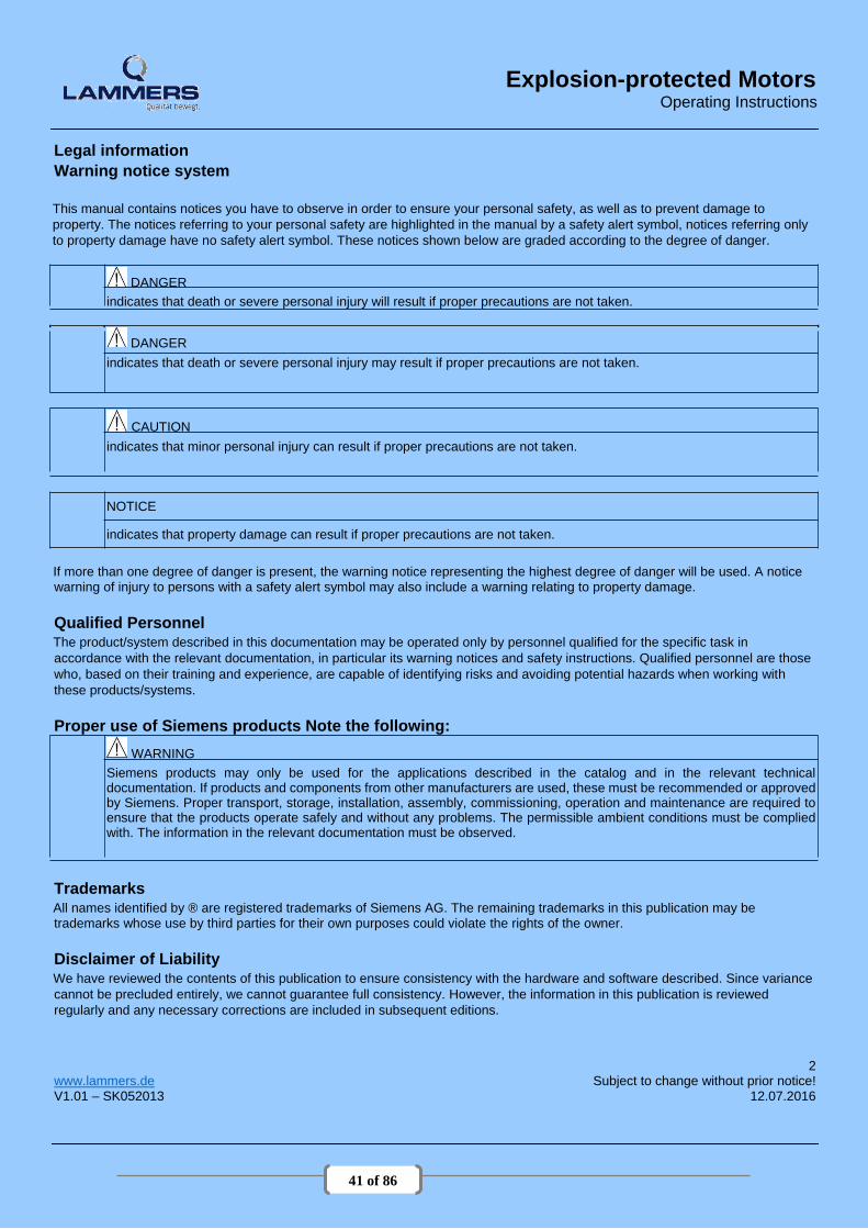
Legal information Warning notice system
This manual contains notices you have to observe in order to ensure your personal safety, as well as to prevent damage to
property. The notices referring to your personal safety are highlighted in the manual by a safety alert symbol, notices referring only
to property damage have no safety alert symbol. These notices shown below are graded according to the degree of danger.
DANGER indicates that death or severe personal injury will result if proper precautions are not taken.
DANGER indicates that death or severe personal injury may result if proper precautions are not taken.
CAUTION indicates that minor personal injury can result if proper precautions are not taken.
NOTICE
indicates that property damage can result if proper precautions are not taken.
If more than one degree of danger is present, the warning notice representing the highest degree of danger will be used. A notice warning of injury to persons with a safety alert symbol may also include a warning relating to property damage.
Qualified Personnel The product/system described in this documentation may be operated only by personnel qualified for the specific task in
accordance with the relevant documentation, in particular its warning notices and safety instructions. Qualified personnel are those
who, based on their training and experience, are capable of identifying risks and avoiding potential hazards when working with
these products/systems.
Proper use of Siemens products Note the following:
WARNING Siemens products may only be used for the applications described in the catalog and in the relevant technical documentation. If products and components from other manufacturers are used, these must be recommended or approved by Siemens. Proper transport, storage, installation, assembly, commissioning, operation and maintenance are required to ensure that the products operate safely and without any problems. The permissible ambient conditions must be complied with. The information in the relevant documentation must be observed.
Trademarks All names identified by ® are registered trademarks of Siemens AG. The remaining trademarks in this publication may be trademarks whose use by third parties for their own purposes could violate the rights of the owner.
Disclaimer of Liability We have reviewed the contents of this publication to ensure consistency with the hardware and software described. Since variance
cannot be precluded entirely, we cannot guarantee full consistency. However, the information in this publication is reviewed
regularly and any necessary corrections are included in subsequent editions.
2 www.lammers.de Subject to change without prior notice! V1.01 – SK052013 12.07.2016

42 of 86
Explosion-protected Motors Operating Instructions
Table of contents
1 Introduction .................................................................................................................................................................................. 4
1.1 Machine types .................................................................................................................................................................... 4
1.2 Information for the reader .................................................................................................................................................. 4
2 Safety notes ................................................................................................................................................................................ 5
2.1 Information for those responsible for the plant or system .................................................................................................. 5
2.2 The five safety rules: .......................................................................................................................................................... 5
2.3 Qualified personnel ............................................................................................................................................................ 6
2.4 Special conditions for explosion-proof machines ............................................................................................................... 7
3 Description .................................................................................................................................................................................. 8
3.1 Regulations ........................................................................................................................................................................ 8
3.2 Regulations for explosion-proof machines ......................................................................................................................... 9
4 Preparing for use ....................................................................................................................................................................... 12
5 Mounting, installation ................................................................................................................................................................. 13
5.1 Installation of explosion-proof machines .......................................................................................................................... 14
5.2 Ventilation ........................................................................................................................................................................ 14
5.3 Minimum dimension "X" for the distance between neighboring modules ......................................................................... 14
5.4 Electromagnetic compatibility........................................................................................................................................... 15
5.5 Balancing ......................................................................................................................................................................... 15
5.6 Alignment and fastening .................................................................................................................................................. 16
6 Electrical connection.................................................................................................................................................................. 17
6.1 Terminal Box .................................................................................................................................................................... 17
6.2 Tightening torques ........................................................................................................................................................... 21
6.3 Conductor connection ...................................................................................................................................................... 23
6.4 General information on connecting the grounding conductor ........................................................................................... 25
6.5 Final checks ..................................................................................................................................................................... 27
6.6 Connecting to the converter ............................................................................................................................................. 28
7 Commissioning .......................................................................................................................................................................... 30
7.1 Insulation resistance ........................................................................................................................................................ 30
7.2 Measures ......................................................................................................................................................................... 32
7.3 Operation ......................................................................................................................................................................... 33
8 Maintenance .............................................................................................................................................................................. 39
8.1 Preparation and notes ...................................................................................................................................................... 39
8.2 Regreasing (optional) ....................................................................................................................................................... 40
8.3 Cleaning ........................................................................................................................................................................... 41
8.4 Bearings ........................................................................................................................................................................... 42
8.5 Dismantling ...................................................................................................................................................................... 43
8.6 Reassembly ..................................................................................................................................................................... 43
9 Spare parts ................................................................................................................. ............................................................... 45
3
www.lammers.de Subject to change without prior notice! V1.01 – SK052013 12.07.2016

43 of 86
Explosion-protected Motors Operating Instructions
1 Introduction
1.1 Machine types 1TE1 / 7AA / 9AA / 14BG / 16BG
1.2 Information for the reader
Ikonen-Erklärung
Note for 1TE1 machines
Note for 1TE1 machines, frame sizes 80 and 90 with central terminal box locking
Information about explosion-protected machines
4 www.lammers.de Subject to change without prior notice! V1.01 – SK052013 12.07.2016

44 of 86
Explosion-protected Motors Operating Instructions
2 Safety notes 2.1 Information for those responsible for the plant or system
This electric machine has been designed and built in accordance with the specifications contained in Directive 2006/95/EC ("Low-Voltage Directive") and is intended for use in industrial plants. Please observe the country-specific regulations when using the electric machine outside the European Community. Follow the local and industry-specific safety and setup regulations. The persons responsible for the plant must ensure the following:
● Planning and configuration work and all work carried out on and with the machine is only to be done by qualified
personnel.
● The operating instructions must always be available for all work.
● The technical data as well as the specifications relating to the permissible installation, connection, ambient and operating conditions are taken into account at all times.
● The specific setup and safety regulations as well as regulations on the use of personal protective equipment are
observed. Note
Use the services and support provided by the appropriate Service Center for planning, installation, commissioning and servicing work.
You will find safety instructions in the individual sections of this document. Follow the safety
instructions for your own safety, to protect other people and to avoid damage to property. Observe the following safety instructions for all activities on and with the machine.
2.2 The five safety rules:
For your personal safety and to prevent material damage when carrying out any work, always
observe the safety instructions and the following five safety rules, according to EN 50110‑ 1 "Working
in a voltage-free state". Apply the five safety rules in the sequence stated before starting work.
Five safety rules Disconnect the system. Disconnect the auxiliary circuits, for example anti-condensation heating. Protect against reconnection. Make sure that the equipment is de-energized (in a no-voltage condition). Ground and short-circuit. Cover or provide barriers around adjacent components that are still live.
5
www.lammers.de Subject to change without prior notice! V1.01 – SK052013 12.07.2016

45 of 86
Explosion-protected Motors Operating Instructions
2.3 Qualified personnel
All work at the machine must be carried out by qualified personnel only. For the purpose of this documentation, qualified personnel is taken to mean people who fulfill the following requirements:
● Through appropriate training and experience, they are able to recognize and avoid risks and potential dangers in their
particular field of activity.
● They have been instructed to carry out work on the machine by the appropriate person responsible..
WARNING Live parts Electrical machines contain live parts. Fatal or severe injuries and substantial material damage can occur if the required covers are removed or if the machines are not handled, operated, or maintained properly.
Only remove covers in compliance with the applicable regulations. Operate the machines properly.
● Perform regular maintenance on the machine.
WARNING Rotating parts Electrical machines contain dangerous rotating parts. Fatal or severe injuries and substantial material damage can occur if the required covers are removed or if the machines are not handled, operated, or maintained properly.
(1) Only remove covers in compliance with the applicable regulations. (2) Operate the machines properly. (3) Perform regular maintenance on the machine. ● Secure free-standing shaft extensions.
WARNING Hot surfaces Electrical machines have hot surfaces. Fatal or severe injuries and substantial material damage can occur if the required covers are removed or if the machines are not handled, operated, or maintained properly.
1) Allow the machine to cool down before starting any work on it. 2) Only remove covers in compliance with the applicable regulations. ● Operate the machines properly.
CAUTION The increased level of danger in hazardous areas demands that you pay particular attention to the notes
marked with . 6 www.lammers.de Subject to change without prior notice! V1.01 – SK052013 12.07.2016

46 of 86
Explosion-protected Motors Operating Instructions
2.4 Special conditions for explosion-proof machines Special conditions for the safe application of explosion-protected machines marked with X (excerpt
from the EC type-examination certificate, point 17) Flameproof enclosure "d"
Flameproof joints may only be repaired strictly in accordance with the manufacturer's design
specifications. Repair in accordance with the values in Tables 1 and 2 of EN / IEC 60079-1 is
not permitted. Zone 21 Do not operate the motors with excessively thick deposits of dust. When the motors are mounted with the free shaft end pointing upwards, prevent foreign bodies from
dropping into the ventilation openings using an appropriate mechanical design. For motors with a fixed connecting cable: The free end of the cable must be connected according to
valid regulations for electrical installations.
7
www.lammers.de Subject to change without prior notice! V1.01 – SK052013 12.07.2016

47 of 86
Explosion-protected Motors Operating Instructions
3 Description
More Information
…can be found on the Internet www.lammers.de. Intended use of the machines
These machines are intended for industrial installations. They comply with the harmonized standards of
the series EN / IEC 60034 (VDE 0530). Their use in hazardous areas is forbidden unless the marking
on the rating plate expressly permits this operation. If other/more wideranging demands (e.g. protection
so that they cannot be touched by children) are made in special cases – i.e. use in non-industrial
installations – these conditions must have been complied with in the plant or system itself when the
motors are installed.
Note Machine directive Low-voltage motors are components designed for installation in machines in accordance with the
current Machinery Directive. They must not be commissioned until it has been verified that the
end product complies with this directive (refer to EN 60204-1).
3.1 Regulations
Machine design
The regulations and standards used as basis to design and test this machine are stamped on the
rating plate. The machine design basically complies with the following standards:
Table 3-1 Applicable general regulations
Feature Standard
Ratings and operating performance EN / IEC 60034-1
Procedure for determining the losses and the efficiency of EN / IEC 60034-2-1 rotating electrical machines and inspections EN / IEC 60034-2-2 EN / IEC 60034-2-3
Degree of protection EN / IEC 60034-5
Cooling EN / IEC 60034-6
Type of construction EN / IEC 60034-7
Terminal designations and direction of rotation EN / IEC 60034-8
Noise emission EN / IEC 60034-9
Restart characteristics for rotating electrical machines EN / IEC 60034-12
Vibration severity grades EN / IEC 60034-14
Efficiency classification of three-phase squirrelcage induction EN / IEC 60034-30 motors
IEC standard voltages IEC 60038
8 www.lammers.de Subject to change without prior notice! V1.01 – SK052013 12.07.2016

48 of 86
Explosion-protected Motors Operating Instructions
3.2 Regulations for explosion-proof machines
Supplementary regulations for explosion-proof machines
Table 3-2 Regulations applied for explosion-proof machines
Feature Standard
Electrical equipment for hazardous gas atmospheres, Part 0: General requirements EN / IEC 60079-0
Electrical equipment for hazardous gas atmospheres, Part 1: Flameproof enclosure "d" EN / IEC 60079-1
Electrical equipment for hazardous gas atmospheres, Part 7: Increased safety "e" EN / IEC 60079-7
Electrical equipment for hazardous gas atmospheres, Part 14: Electric installations for endangered EN / IEC 60079-14 atmospheres (except underground excavation)
Electrical equipment for hazardous gas atmospheres, Part 15: Type of protection "n" EN / IEC 60079-15
Electrical equipment for hazardous gas atmospheres, Part 19: Repairs and overhauls EN / IEC 60079-19
Potentially explosive atmosphere - Part 31: Device dust explosion protection by enclosure "t" EN / IEC 60079-31
Electrical equipment for use in the presence of combustible dust - Part 17: Inspection and EN / IEC 60079-17 maintenance of electrical systems in hazardous areas (except underground excavation)
Directive on the approximation of the laws of the Member RL94/9/EC RL94/9/EG States concerning equipment and protective systems intended for use
in hazardous areas.
Forced ventilation (optional): Type of cooling IC 416 in accordance with EN / IEC 60034-6
WARNING Hot surfaces Operating the machine without external fan results in overheating. This may result in personal injury and material damage. Never commission the machine without an external fan.
Cooling that does not depend on the speed is achieved by means of a separately driven fan wheel (forced ventilation). Forced ventilation does not depend on the operating state of the machine. The fan wheel for the external flow of cooling air is powered by an independent module and is enclosed
by the fan cover. .
9
www.lammers.de Subject to change without prior notice! V1.01 – SK052013 12.07.2016

49 of 86
Explosion-protected Motors Operating Instructions
Types of construction/Installation conditions for explosion-proof machines
The type of construction of the machine is stated on the rating plate.
DANGER In the case of explosion-proof machines where the shaft extensions point downwards (types of construction IM V5, IM V1 or IM V18 ) a protective top cover is mandatory. Explosion-proof machines with IM V5, IM V1 and IM V18 types of construction are fitted with a canopy at the factory.
● For types of construction with a shaft extension facing upwards, a suitable cover must be fitted to prevent small parts from falling into the fan cover (see also standard IEC / EN 60079-0).
● Prevent the cooling airflow from being reduced as a result of covers that might be in place.
The degree of protection the machines feature is stated on the rating plate. They can be installed in dusty or
humid environments.
WARNING Dangerous voltage Condensation drain holes (optional) Inserting objects into the condensation drain holes can damage the winding and can result in death, serious injury and damage to property! Note the following to maintain the degree of protection:
1. Switch off the machine so that it is in a no-voltage condition, before you open the
condensation drain holes. ● Close the condensation drain holes (e.g. using T-plugs) before commissioning the machine.
Note Storage If the machines are used or stored outdoors, we recommend keeping them under a shelter or an
additional cover.
● Avoid exposing them to direct, intense solar radiation, rain, snow, ice, or dust for extended periods.
● If necessary, please consult us or seek advice regarding technical issues.
Enviromental requirements
The machines are suitable for operation in tropical climates. Guide value for the standard version 60 % relative humidity at an ambient temperature of (Tamb) 40 °C.
Ambient temperature: -20 °C to +40 °C Installation altitude: ≤ 1000 m Air with normal oxygen content, usually 21 % (V/V) If the environmental requirements are different from the details listed here, then the values on the rating
plate will apply.
3.2.1 Optional built-on and built in accessories for explosion proof machines
Investigate the influence of sources of heat and cold on the finished installation when it includes built-on
accessories compliant with EN 60079-14!
10 www.lammers.de Subject to change without prior notice! V1.01 – SK052013 12.07.2016

50 of 86
Explosion-protected Motors Operating Instructions Table 3-3 Recommended maximum interface temperatures for flange motors
Type of protection Ex d Ex e, Ex nA
Supply voltage Line Converter Line
Control range - 10 Hz bis fN (≤ 60 Hz) -
Cooling method Self-ventilated
Frame size 63 ... 200
Mechanical design EN 50347
Ambient temperature -20 °C ... +60 °C -20 °C ... +40 °C
Temperature class T3, T4 T3
Number of poles 2, 4 2 4
Max. shaft temperature 100 °C 60 °C 75 °C
Max. flange temperature 100 °C 60 °C 75 °C
Select mounted equipment such as brakes, forced ventilation or incremental encoders according to
the requirements of the Directive 94/9/EC. 11
www.lammers.de Subject to change without prior notice! V1.01 – SK052013 12.07.2016

51 of 86
Explosion-protected Motors Operating Instructions
4 Preparing for use
WARNING Use lifting eyes The machine must only be transported and lifted using the lifting eyes, in a position that is appropriate for its type of construction. Otherwise, it could fall over or slip in the lifting tackle. This can result in death, serious injury, or material damage. ● Use all the lifting eyes on the machine. ● Any eyes that are screwed in must be tightly fastened. ● Eyebolts must be screwed in right up to their supporting surface.
● If necessary, use suitable, sufficiently-sized transport equipment such as lifting straps (EN1492-1) and lashing straps
(EN12195-2).
WARNING Suspended transport If several items of transport material are used for fastening, two straps must be able to carry the whole load. ● Use additional, suitable means of support for transport and during installation.
● Secure the support equipment to prevent it from slipping.
Storage time Turn the shafts 1x every year to avoid bearing brinelling. Prolonged storage periods reduce the useful life
of the bearing grease (aging).
Open bearings
● For open bearings e.g. 1Z, check the state of the bearing grease over 12 months.
● Replace the grease if it can be identified that the grease has lost oil content or has become dirty (ingress of
condensation leads to consistency changes of the grease).
Closed bearings ● For closed bearings, replace the DE and NDE bearings after a storage time of 48 months
12 www.lammers.de Subject to change without prior notice! V1.01 – SK052013 12.07.2016

52 of 86
Explosion-protected Motors Operating Instructions
5 Mounting, installation
WARNING Hot surfaces Electrical machines have hot surfaces. Fatal or severe injuries and substantial material damage can occur if the required covers are removed or if the machines are not handled, operated, or maintained properly. ● Allow the machine to cool down before starting any work on it. ● Only remove covers in compliance with the applicable regulations. ● Operate the machines properly. It must be ensured that parts (cables etc.) do not come into contact with the machine enclosure.
NOTICE
Before start-up, please check that
● the customer has set the correct direction of rotation of the machine - e.g. by decoupling from the driven
machine - by taking appropriate measures! ● there are no temperature-sensitive parts (cables etc.), which are in contact with the machine enclosure.
● condensation drain holes are always located at the lowest point of the motor!
Note Please note the technical data on the rating plates on the machine enclosure.
CAUTION The increased level of danger in hazardous areas demands that you pay particular attention to the notes
marked with .
13
www.lammers.de Subject to change without prior notice! V1.01 – SK052013 12.07.2016

53 of 86
Explosion-protected Motors Operating Instructions
5.1 Installation of explosion-proof machines
● Only use explosion-protected machines in appropriate areas in accordance with directive 1999/92/EG . If the certificate is supplemented by an X, observe the special conditions listed in the EC type examination certificate.
Special conditions for explosion-proof machines (Page 9)
● When installing electrical systems in hazardous zones, observe EN / IEC 60079-14 and the corresponding country regulations.
● Die auf dem Leistungsschild angegebene Temperaturklasse der Maschine muss mit der Temperaturklasse der
möglicherweise auftretenden brennbaren Gase gleich oder höher sein.
5.2 Ventilation
CAUTION Ventilation ● Do not obstruct ventilation. ● Prevent the air expelled by neighboring equipment from being immediately sucked in again. ● On the vertical type of machine construction with air intake from above, protect the air inlets from the ingress of
foreign bodies and water. ● If the shaft extension is facing upwards, liquid must be prevented from entering by moving along the shaft.
5.3 Minimum dimension "X" for the distance between neighboring modules Table 5-1Minimum dimension "X" for the distance between neighboring modules
Frame size X [mm]
63 ... 71 15
80 ... 100 20
112 25
132 30
160 40
180 ... 225 45
180 ... 200 (1LG) 90
225 ... 250 (1LG, 1MA6) 100
280 ... 315 110
14 www.lammers.de Subject to change without prior notice! V1.01 – SK052013 12.07.2016

54 of 86
Explosion-protected Motors Operating Instructions
5.4 Electromagnetic compatibility
Note If the torque levels are very unequal (e.g. when a reciprocating compressor is being driven), a non - sinusoidal machine current will be induced whose harmonics can have an impermissible effect on the supply system and cause impermissible interference emissions as a result.
Note Converter
● If operated with a frequency converter, the emitted interference varies in strength, depending on the
design of the converter (type, interference suppression measures, manufacturer).
● Prevent the limit values stipulated by EN / IEC 61000-6-3 for the drive system (consisting of the machine and converter) from being exceeded.
● You must observe the EMC information from the manufacturer of the converter.
● The most effective method of shielding is to conductively connect a shielded machine supply cable to
the metal terminal box of the machine (with a metal screw connection) over a large surface area.
● On machines with integrated sensors (e.g. PTC thermistors), disturbance voltages caused by the converter may occur on the sensor cable.
5.5 Balancing
CAUTION Safety precautions ● The general touch protection measures for drive output elements must be observed. ● Output elements may only be attached or withdrawn using the correct equipment.
● The feather keys are only secured against falling out during shipping. If you commission a machine without an
output element, the feather keys must be secured to prevent them from being thrown out.
The rotors are balanced dynamically. The balancing quality corresponds to vibration severity grade "A" for the complete machine as standard. The optional vibration severity grade "B" is indicated on the rating plate. The declaration regarding the type of featherkey for balancing is generally marked on the rating plate
and optionally on the face of the shaft end.
Designation:
● As a standard measure, balancing is carried out dynamically with a half featherkey (code "H") in accordance with ISO 8821.
● "F" means balancing with a whole featherkey (optional version).
● "N" means balancing without a featherkey (optional version).
Note Measures conforming to ISO 10816 must be taken in order to compensate any offset between
electrical machines and driven machines. The foundation must be designed according to DIN 4024.
15
www.lammers.de Subject to change without prior notice! V1.01 – SK052013 12.07.2016
55 of 86
Explosion-protected Motors Operating Instructions
5.6 Alignment and fastening General
When aligning and fastening the machine, please bear the following in mind:
● The machine must be level.
● Feet and flanges must be fastened securely.
● Alignment must be precise in the case of direct coupling.
● Fastening surfaces must be clean
● Look out for any damage to paint; this must be rectified immediately and correctly.
● Look out for traces of anti-corrosion protection agents; these must be removed using mineral turpentine.
● Look out for installation-related resonances with the rotating frequency and double line frequency; these must be prevented.
● Listen for unusual noises when turning the rotor manually.
● Check the direction of rotation with the machine decoupled.
● Avoid using rigid coupling measures.
Flatness of the supporting surfaces for conventional motors
Frame size Flatness
≤ 132 0,10
160 0,15
≥ 180 0,20
16 www.lammers.de Subject to change without prior notice! V1.01 – SK052013 12.07.2016

56 of 86
Explosion-protected Motors Operating Instructions
6 Electrical connection
WARNING Note the following safety information before connecting-up the machine: ● Only qualified and trained personnel should carry out work on the machine while it is stationary. ● Disconnect the machine from the power supply and take measures to prevent it being reconnected. This also
applies to auxiliary circuits, e.g. anti-condensation heating. ● Check that the machine really is in a no-voltage condition. ● Establish a safe protective conductor connection before starting any work.
● If the incoming power supply system displays any deviations from the rated values in terms of voltage,
frequency, curve form or symmetry, such deviations will increase the temperature and influence electromagnetic compatibility.
WARNING Line supply with non-grounded neutral point Operating the machine on a line supply system with a non-grounded neutral point is only permitted over short time intervals that occur rarely, e.g. the time leading to a fault being eliminated (ground fault of a cable, EN 60034-1).
The following features make this type of electrical connection different from that for standard machines:
● Maintain the area A in EN / IEC 60034-1 (VDE 0530-1) (±5 % voltage or ±2 % frequency deviation,
waveform, line supply symmetry) so that the temperature rise remains within the permissible limits.
● Larger deviations from the rated data may result in electrical machines heating up to impermissible levels. This information must be specified on the rating plate. Under no circumstances exceed the limits!
● Protect every machine with type of protection increased safety "e" in accordance with EN / IEC
60079-14 against an inadmissible temperature rise using a current-dependent, delayed circuit breaker with phase failure protection and asymmetry detection corresponding to EN / IEC 60947 or using an equivalent device in all phases.
● For machines with type of protection increased safety "e", select the overcurrent device with current-
dependent delayed trip so that the tripping time, which should be taken from the characteristic of the switch for the ratio IA / IN of the machine to be protected, is no longer than the safe-locked rotor time tE. Take the ratio IA / IN as well as the safe-locked rotor time tE from the rating plate. Set the protective device to the rated current. Use a certified tripping unit in accordance with RL 94/9/EC For machines with increased safety "e" type of protection, in the event of a locked rotor the protective device must disconnect within the tE time specified for the relevant temperature class. Protect electrical machines for heavy duty starting (acceleration time > 1.7 x tE time) according to the specifications of the EC-type examination certificate using a starting monitoring function. Direct monitoring of the winding temperature is permissible as a means of thermal machine
protection, provided that this is certified and specified on the rating plate.
● With pole-changing machines, separate, interlocked protective devices are required for each speed step. Devices with an EC-type examination certificate are recommended.
● . 6.1 Terminal Box
DANGER
17
www.lammers.de Subject to change without prior notice! V1.01 – SK052013 12.07.2016

57 of 86
Explosion-protected Motors Operating Instructions
Dangerous voltage Electric machines contain hazardous voltages. If the machine is not de-energized and brought into a no-voltage condition, death or serious injury will occur.
When work is carried out on the machine with the terminal box open, it must not be electrically connected!
NOTICE
Damage to property Note the following information to avoid damage to the terminal box.
● Make sure that the components inside the terminal box e.g. terminal board and cable connections) are not
damaged! ● It must be ensured that there are no foreign bodies, dirt or moisture in the terminal box. Cable entries into the
terminal box according to DIN 42925. ● Close any additional open cable entries with O-rings or suitable flat gaskets, the terminal box itself must be sealed
so that it is dust and water tight using the original seal. ● Please observe the tightening torques for cable glands and other screws. ● When performing a test run, secure the feather keys without output elements.
Note The terminal box must be sealed so that dust and water cannot enter.
Standardausführung It is possible to turn the top side of a machine terminal box 4 x 90 degrees (if screwed on).
6.1.1 Connection with cable lug for explosion-protected machines
NOTICE
Connection using cable lugs You must bend single-core line conductors into a U shape in order to prevent the contact force being transferred at just one side. In order to prevent the cable lug from rotating, for a line connection using a cable lug, angle single- or multi-core cables through approx. 40° downwards!
6.1.2 Protruding connection cables
WARNING Short-circuit hazard During disassembly and particularly when installing the cover plate, make sure that the connection cables are not clamped between enclosure parts and the cover plate.
18 www.lammers.de Subject to change without prior notice! V1.01 – SK052013 12.07.2016
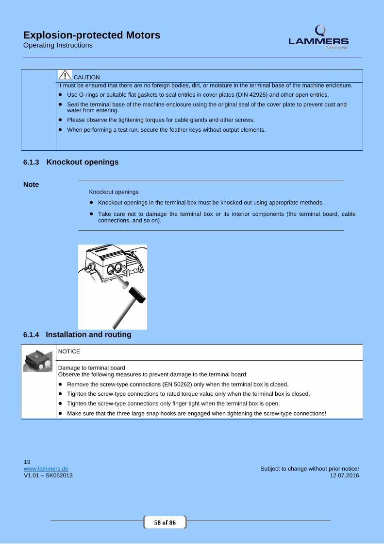
58 of 86
Explosion-protected Motors Operating Instructions
CAUTION It must be ensured that there are no foreign bodies, dirt, or moisture in the terminal base of the machine enclosure. ● Use O-rings or suitable flat gaskets to seal entries in cover plates (DIN 42925) and other open entries. ● Seal the terminal base of the machine enclosure using the original seal of the cover plate to prevent dust and
water from entering. ● Please observe the tightening torques for cable glands and other screws. ● When performing a test run, secure the feather keys without output elements.
6.1.3 Knockout openings
Note Knockout openings
● Knockout openings in the terminal box must be knocked out using appropriate methods.
● Take care not to damage the terminal box or its interior components (the terminal board, cable
connections, and so on).
6.1.4 Installation and routing
NOTICE
Damage to terminal board Observe the following measures to prevent damage to the terminal board: ● Remove the screw-type connections (EN 50262) only when the terminal box is closed. ● Tighten the screw-type connections to rated torque value only when the terminal box is closed. ● Tighten the screw-type connections only finger tight when the terminal box is open. ● Make sure that the three large snap hooks are engaged when tightening the screw-type connections!
19
www.lammers.de Subject to change without prior notice! V1.01 – SK052013 12.07.2016

59 of 86
Explosion-protected Motors Operating Instructions
6.1.5 Thread sizes
Table 6-1Thread sizes in the cast iron terminal box Frame size Standard thread Additional thread
with mounting parts
80
90
100 M32x1,5 2 Stk. M16x1,5 1 Stk.
112 M32x1,5 2 Stk. M16x1,5 1 Stk.
132 M32x1,5 2 Stk. M16x1,5 1 Stk.
160 M40x1,5 2 Stk. M16x1,5 1 Stk.
180 M40x1,5 2 Stk. M16x1,5 1 Stk.
200 M50x1,5 2 Stk. M20x1,5 1 Stk.
225 M50x1,5 2 Stk. M20x1,5 1 Stk.
250 M63x1,5 2 Stk. M20x1,5 1 Stk.
280 M63x1,5 2 Stk. M20x1,5 1 Stk.
315 M63x1,5 2 Stk. M20x1,5 1 Stk.
20 www.lammers.de Subject to change without prior notice! V1.01 – SK052013 12.07.2016
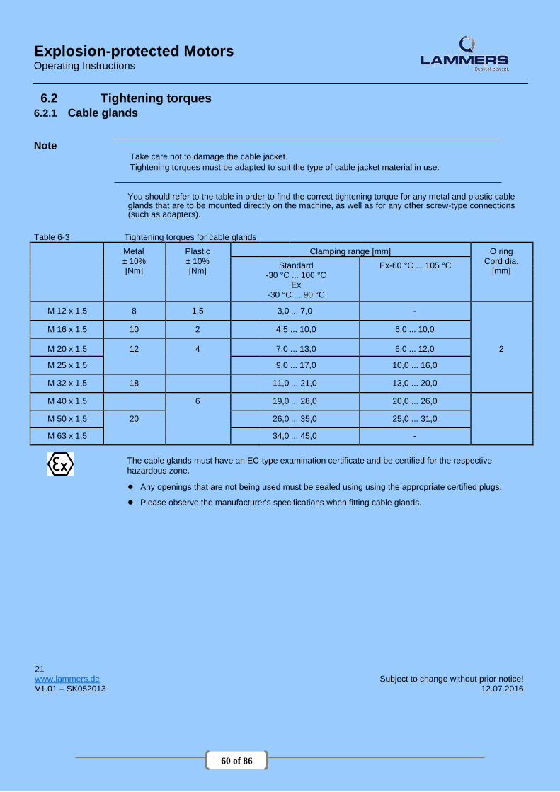
60 of 86
Explosion-protected Motors Operating Instructions
6.2 Tightening torques 6.2.1 Cable glands
Note Take care not to damage the cable jacket. Tightening torques must be adapted to suit the type of cable jacket material in use.
You should refer to the table in order to find the correct tightening torque for any metal and plastic cable glands that are to be mounted directly on the machine, as well as for any other screw-type connections (such as adapters).
Table 6-3 Tightening torques for cable glands
Metal Plastic Clamping range [mm] O ring ± 10% ± 10%
Standard Ex-60 °C ... 105 °C Cord dia.
[Nm] [Nm]
[mm] -30 °C ... 100 °C
Ex
-30 °C ... 90 °C
M 12 x 1,5 8 1,5 3,0 ... 7,0 -
M 16 x 1,5 10 2 4,5 ... 10,0 6,0 ... 10,0
M 20 x 1,5 12 4 7,0 ... 13,0 6,0 ... 12,0 2
M 25 x 1,5 9,0 ... 17,0 10,0 ... 16,0
M 32 x 1,5 18 11,0 ... 21,0 13,0 ... 20,0
M 40 x 1,5 6 19,0 ... 28,0 20,0 ... 26,0
M 50 x 1,5 20 26,0 ... 35,0 25,0 ... 31,0
M 63 x 1,5 34,0 ... 45,0 -
The cable glands must have an EC-type examination certificate and be certified for the respective
hazardous zone.
● Any openings that are not being used must be sealed using using the appropriate certified plugs.
● Please observe the manufacturer's specifications when fitting cable glands.
21
www.lammers.de Subject to change without prior notice! V1.01 – SK052013 12.07.2016

61 of 86
Explosion-protected Motors Operating Instructions
6.2.2 Terminal boxes, end shields, grounding conductors, sheet metal fan covers
Note The specified tightening torques are applicable unless other values are indicated.
Table 6-4 Tightening torques for screws on the terminal box, end shields, screw-type grounding conductor connections
Thread ∅ M 4 M 5 M 6 M 8 M 10 M 12 M 16 M20
Nm min 2 3,5 6 16 28 46 110 225
max 3 5 9 24 42 70 165 340
Table 6-5 Tightening torques for self-tapping screws on the terminal box, end shields, screw-type grounding
conductor connections, sheet metal fan covers
Gewinde ∅ M 4 M 5 M 6
Nm min 4 7,5 12,5
max 5 9,5 15,5
22 www.lammers.de Subject to change without prior notice! V1.01 – SK052013 12.07.2016

62 of 86
Explosion-protected Motors Operating Instructions
6.3 Conductor connection 6.3.1 General information on conductor connection
Cross-sections that can be connected depending on the size of the terminal (possibly reduced due to size
of cable entries)
WARNING Short-circuit hazard Electric machines contain hazardous voltages. If the appropriate precautions are not taken, death or serious physical injury can occur. ● Do not lay connection cables over the central dome of the terminal board. ● Observe the opening direction and the mounting position of the cover washers on the terminal board.
Table 6-6 Max. conductor connection for standard machines and Zone 22
Frame size Max. connectable conductor cross-section [mm²]
56 ... 90 1,5 2,5 with cable lug
100 ... 112 4,0
132 6,0
160 ... 180 16,0
200 25,0
225 35,0 with cable lug
250 ... 280 120,0
315 240,0
Table 6-7 Max. conductor connection for explosion-proof machines (with the exception of Zone 22 and 1MJ) and VIK
standard version
Baugröße Max. anschließbarer Leiterquerschnitt [mm²]
56 ... 112 4,0
132 6,0
160 16,0
180 10,0
180 (1LG4, 1LG6) 16,0
200 ... 225 50,0
250 ... 280 120,0
315 240,0
23
www.lammers.de Subject to change without prior notice! V1.01 – SK052013 12.07.2016
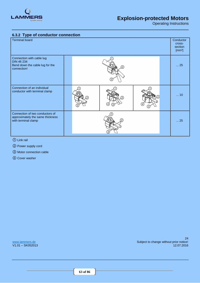
63 of 86
Explosion-protected Motors Operating Instructions
6.3.2 Type of conductor connection
Terminal board Conductor cross-
section
[mm²]
Connection with cable lug DIN 46 234
Bend down the cable lug for the ... 25
connection!
Connection of an individual conductor with terminal clamp
... 10
Connection of two conductors of approximately the same thickness
with terminal clamp ... 25
① Link rail
② Power supply cord
③ Motor connection cable
④ Cover washer
24 www.lammers.de Subject to change without prior notice! V1.01 – SK052013 12.07.2016
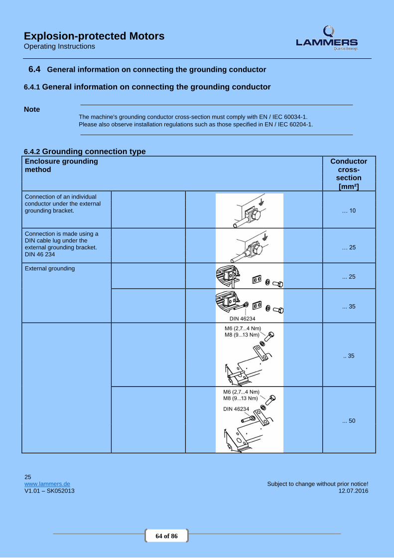
64 of 86
Explosion-protected Motors Operating Instructions
6.4 General information on connecting the grounding conductor
6.4.1 General information on connecting the grounding conductor Note
The machine's grounding conductor cross-section must comply with EN / IEC 60034-1. Please also observe installation regulations such as those specified in EN / IEC 60204-1.
6.4.2 Grounding connection type
Enclosure grounding Conductor method cross-
section
[mm²]
Connection of an individual conductor under the external
grounding bracket. … 10
Connection is made using a DIN cable lug under the
… 25 external grounding bracket.
DIN 46 234
External grounding
... 25
... 35
.. 35
... 50
25
www.lammers.de Subject to change without prior notice! V1.01 – SK052013 12.07.2016

65 of 86
Explosion-protected Motors Operating Instructions
Table 6-9 Minimum cross-sectional area of grounding conductor
Minimum cross-sectional area of phase Minimum surface area of associated grounding conductor for installation connection
S [mm²]
[mm²]
S ≤ 16 S
16 < S ≤ 35 16
S > 35 0,5 S
Table 6-10 Size of grounding conductor screw (except for 1MJ machines)
Frame size Thread size for the grounding conductor
63 ... 90 M3,5 / M4
100 ... 112 M5
132 ... 180 M6
200 ... 225 M8
200 1LG4/6, 1TE1 2x M6
200 ... 315 1LG, 1TE1, 1MA 2x M8 For machines of size 80 ... 90 with central terminal-box locking, the ground conductor can also be connected with a cable lug in accordance with DIN46237, size M4.
Table 6-11 Size of grounding conductor screw for 1MJ machines.
Frame size Thread size for the grounding conductor
71 ... 180 2x M6
200 ... 315 2x M8
26 www.lammers.de Subject to change without prior notice! V1.01 – SK052013 12.07.2016

66 of 86
Explosion-protected Motors Operating Instructions
6.5 Final checks
Before closing the terminal box/terminal base of the machine enclosure, check the following:
● Establish the electrical connections in the terminal box in accordance with the details in the sections above and tighten with the correct torque.
● The clearances between non-insulated parts have been maintained: ≥ 5.5 mm to 690 V, ≥ 8 mm to 1000
V.
● Avoid protruding wire ends!
● In order not to damage the cable insulation, freely arrange the connecting cables.
● Connect the machine corresponding to the specified direction of rotation.
● Keep the inside of the terminal box clean and free from trimmed-off ends of wire.
● Ensure that all seals and sealing surfaces are undamaged and clean.
6.6 Connecting to the converter
● Correctly and professionally close unused openings in the terminal boxes.
● The pressure relief device is undamaged (depending on the type of terminal box, this involves either cast-in slots or an overpressure diaphragm). Only repair damage after prior consultation with the person responsible for the safety of the equipment and use only original parts.
Before closing the terminal box, check that
● the air clearances for explosion-protected machines (with the exception of machines for Zone 22) between
non-insulated parts are maintained: ≥ 10 mm to 690 V.
● the minimum creepage distance for explosion-protected machines (with the exception of machines for Zone 22) between non-insulated parts is maintained: ≥ 12 mm to 690 V.
27
www.lammers.de Subject to change without prior notice! V1.01 – SK052013 12.07.2016

67 of 86
Explosion-protected Motors Operating Instructions
6.6 Connecting to the converter
CAUTION The standard insulation system is designed so that operation on the converter is possible for supply voltages up to 500 V +10% in motorized operation. Use a special insulation system or adopt special measures, e.g. output filter, for higher voltages.
NOTICE
Machines must always be connected to frequency converters using shielded machine supply cables. The most effective method of shielding is to conductively connect the cable to the metal terminal box of the machine (with metal screw connections) over a large surface area.
Note EMC
Please observe the section containing instructions on ensuring electromagnetic compatibility.
See the list of additional operating instructions: SIEMENS Service Center (Page 61)
WARNING Operating explosion-protected machines on a converter Always with PTC thermistor monitoring. For this purpose, tripping units according to directive 94/9/EC are necessary.
Machines with increased safety "e" type of protection Converter operation for these machines must be expressly certified. It is essential that you observe the separate manufacturer's information and instructions. Converter and protective devices must be marked as belonging together and the permitted operating data must be defined in the common EC-type examination certificate.
Machines operated from a converter for Zone 21 and Zone 22 These machines are generally equipped with three PTC thermistors in accordance with DIN 44082 with a rated response temperature that depends on the maximum possible surface temperature. Select the PTC thermistors in accordance with this standard. The maximum temperature at the cable entries is 120° C. Use suitable cables for this temperature. Do not exceed the maximum frequency dependent on the number of poles, which is stamped on the rating plate.
System, converter-cable-electrical machine Please observe the information in accordance with EN / IEC 60034-17 and EN / IEC 60034-25 regarding
winding stress. For line supplies with operating voltages up to 690 V, the maximum value of the voltage
peaks at the end of the cable must not exceed twice the value of the converter's DC-link voltage. 28 www.lammers.de Subject to change without prior notice! V1.01 – SK052013 12.07.2016

68 of 86
Explosion-protected Motors Operating Instructions
Machines with type of protection flameproof enclosure "d" or "de" Temperature sensors for tripping These machines are equipped with three temperature sensors in the winding and one temperature sensor in the gland plate in order that the temperature class is maintained. Connect the temperature sensors in series according to the circuit diagram. Temperature sensors for alarm and trip These machines have for warning and shutdown three temperature sensors in the winding and one temperature sensor in the gland plate. Connect the temperature sensors in series according to the circuit diagram.
29
www.lammers.de Subject to change without prior notice! V1.01 – SK052013 12.07.2016

69 of 86
Explosion-protected Motors Operating Instructions
7 Commissioning 7.1 Insulation resistance
WARNING Working on electrical power installations Only appropriately trained personnel may carry out this work. Before starting commissioning, install all covers that are designed to prevent active or rotating parts from being touched, or which are necessary to ensure correct air guidance and thus effective cooling.
WARNING Hazardous voltage at the terminals Dangerous voltages are sometimes present on the terminals during and immediately after measurement of the winding insulation resistance. Contact with these can result in death, serious injury or material damage. If any power cables are connected, check to make sure line supply voltage cannot be connected. Once you have measured the insulation resistance, discharge the winding by connecting to the ground potential
Checking the insulation resistance
NOTICE
The insulation resistance needs to be checked prior to start-up and again after any extended periods of storage or periods during which the equipment is not in operation. Before you begin measuring the insulation resistance, please read the operating manual for the insulation resistance meter you are going to use. Disconnect any main-circuit cables that are connected to the terminals before measuring the insulation resistance.
Note If the critical insulation resistance is less than or equal to this value, the windings must be dried or, if the fan
is removed, cleaned thoroughly and dried. Please note that the insulation resistance of dried, clean windings is lower than that of warm windings. The
insulation resistance can only be properly assessed after conversion to the reference temperature of 25 °C.
Note
If the measured value is close to the critical value, you must check the insulation resistance at
suitably frequent intervals.
Measuring the insulation resistance
1. Before you begin measuring the insulation resistance, please read the operating manual for the insulation resistance meter you are going to use.
2. Disconnect any main circuit cables from the terminals before measuring the insulation resistance. 3. Where possible, measure the insulation resistance of the winding with respect to the motor enclosure when
the winding temperature is between 20 ... 30 °C. Different insulation resistance values apply for other temperatures.
4. When measuring, wait until the final resistance value is reached. This is reached after approximately one minute. Then read off the insulation resistance.
. 30 www.lammers.de Subject to change without prior notice! V1.01 – SK052013 12.07.2016
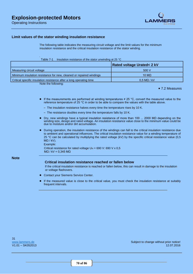
70 of 86
Explosion-protected Motors Operating Instructions
Limit values of the stator winding insulation resistance
The following table indicates the measuring circuit voltage and the limit values for the minimum insulation resistance and the critical insulation resistance of the stator winding.
.
Table 7-1 Insulation resistance of the stator unwinding at 25 °C
Rated voltage Urated< 2 kV
Measuring circuit voltage 500 V
Minimum insulation resistance for new, cleaned or repaired windings 10 MΩ
Critical specific insulation resistance after a long operating time 0,5 MΩ / kV
Note the following: ● 7.2 Measures
● If the measurements are performed at winding temperatures ≠ 25 °C, convert the measured value to the reference temperature of 25 °C in order to be able to compare the values with the table above.
– The insulation resistance halves every time the temperature rises by 10 K. – The resistance doubles every time the temperature falls by 10 K.
● Dry, new windings have a typical insulation resistance of more than 100 ... 2000 MΩ depending on the
winding size, design and rated voltage. An insulation resistance value close to the minimum value could be due to moisture and/or dirt accumulation.
● During operation, the insulation resistance of the windings can fall to the critical insulation resistance due
to ambient and operational influences. The critical insulation resistance value for a winding temperature of
25 °C can be calculated by multiplying the rated voltage (kV) by the specific critical resistance value (0,5
MΩ / kV). Example: Critical resistance for rated voltage UN = 690 V: 690 V x 0,5
MΩ / kV = 0,345 MΩ Note
Critical insulation resistance reached or fallen below If the critical insulation resistance is reached or fallen below, this can result in damage to the insulation
or voltage flashovers.
● Contact your Siemens Service Center.
● If the measured value is close to the critical value, you must check the insulation resistance at suitably frequent intervals.
31
www.lammers.de Subject to change without prior notice! V1.01 – SK052013 12.07.2016

71 of 86
Explosion-protected Motors Operating Instructions
7.2 Measures Measures before commissioning
Once the system has been correctly installed, you should check the following prior to commissioning:
● The machine has been assembled and aligned correctly.
● The machine has been connected so that it rotates in the direction specified.
● The operating conditions match the data specified on the rating plate.
● The bearings have been lubricated as appropriate for the version used. Rolling-contact bearing machines which have been in storage for more than 24 months have been relubricated.
● Any supplementary machine monitoring equipment has been connected correctly and is functioning as it
should. 7.2 Measures
● For versions with bearing thermometers, the bearing temperatures must be checked during the machine's first period of operation. The warning and shutdown values are set on the monitoring device.
● Appropriately configured control and speed monitoring functions ensure that the machine cannot exceed
the permissible speeds specified on the rating plate.
● The output elements have the correct settings for their type (e.g. alignment and balancing of couplings, belt forces in the case of a belt drive, tooth forces and tooth face clearance in the case of toothed-wheel power output, radial and axial clearance in the case of coupled shafts).
● The minimum insulation resistance and minimum clearance values have been adhered to. ● The grounding
and equipotential bonding connections have been established correctly.
● All fixing screws, connection elements, and electrical connections have been tightened to the specified torques.
● Lifting eyes that were screwed in have been removed following installation or secured to prevent them
becoming loose.
● The rotor can turn without coming into contact with the stator.
● All touch protection measures for both moving and live parts have been implemented.
● In cases where the shaft extension is not being used and is, therefore, exposed, it has been covered and the feather key has been secured to prevent it from being thrown out.
● If being used, the external fan is ready for operation and connected so that it rotates in the direction specified.
● The flow of cooling air is not obstructed.
● If a brake is being used, it is functioning correctly.
● The specified mechanical limit speed n max is adhered to. If the design of the machine requires the converter to be assigned in a particular way, the relevant
information will be provided on the rating plate or an additional label.
Note It may be necessary to perform additional checks and tests in accordance with the specific situation on site.
Measures for start-up
After installation or inspections, the following measures are recommended for normal start-up of
the machines:
● Start the machine without a load; to do this, close the motor starter protector and do not switch the machine off prematurely. You should limit how often you switch the machine off while it is starting up and still running at a slow speed, for checking the direction of rotation or the required dimensions, for example. Allow the machine to run to a standstill before switching it back on again.
32 www.lammers.de Subject to change without prior notice! V1.01 – SK052013 12.07.2016
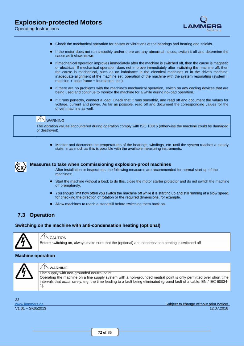
72 of 86
Explosion-protected Motors Operating Instructions
● Check the mechanical operation for noises or vibrations at the bearings and bearing end shields.
● If the motor does not run smoothly and/or there are any abnormal noises, switch it off and determine the cause as it slows down.
● If mechanical operation improves immediately after the machine is switched off, then the cause is magnetic
or electrical. If mechanical operation does not improve immediately after switching the machine off, then
the cause is mechanical, such as an imbalance in the electrical machines or in the driven machine,
inadequate alignment of the machine set, operation of the machine with the system resonating (system =
machine + base frame + foundation, etc.).
● If there are no problems with the machine's mechanical operation, switch on any cooling devices that are being used and continue to monitor the machine for a while during no-load operation.
● If it runs perfectly, connect a load. Check that it runs smoothly, and read off and document the values for
voltage, current and power. As far as possible, read off and document the corresponding values for the driven machine as well.
WARNING The vibration values encountered during operation comply with ISO 10816 (otherwise the machine could be damaged or destroyed).
● Monitor and document the temperatures of the bearings, windings, etc. until the system reaches a steady
state, in as much as this is possible with the available measuring instruments.
Measures to take when commissioning explosion-proof machines After installation or inspections, the following measures are recommended for normal start-up of the
machines:
● Start the machine without a load; to do this, close the motor starter protector and do not switch the machine off prematurely.
● You should limit how often you switch the machine off while it is starting up and still running at a slow speed,
for checking the direction of rotation or the required dimensions, for example.
● Allow machines to reach a standstill before switching them back on.
7.3 Operation
Switching on the machine with anti-condensation heating (optional)
CAUTION Before switching on, always make sure that the (optional) anti-condensation heating is switched off.
Machine operation
WARNING Line supply with non-grounded neutral point Operating the machine on a line supply system with a non-grounded neutral point is only permitted over short time intervals that occur rarely, e.g. the time leading to a fault being eliminated (ground fault of a cable, EN / IEC 60034-1).
33
www.lammers.de Subject to change without prior notice! V1.01 – SK052013 12.07.2016

73 of 86
Explosion-protected Motors Operating Instructions
WARNING Do not remove covers when the motor is running Rotating or live parts are dangerous. Death, serious injury, or material damage can result if the required covers are removed. ● De-energize the machine and bring it into a no voltage condition before removing any covers.
● Ensure that any covers, which are designed to prevent active or rotating parts from being touched, which are
necessary to ensure correct air guidance and thus effective cooling, or which guarantee the degree of protection of the machine, remain closed during operation.
CAUTION The surfaces of the machines can reach high temperatures, which can lead to burns if touched.
NOTICE
Minimum load for cylindrical roller bearings Be sure to comply with the minimum radial load of 30% of the cylindrical roller bearings in accordance with catalog data.
WARNING Faults during operation Deviations from conditions during normal operation, such as an increase in power consumption, temperatures or vibrations, unusual noises or odors, tripping of monitoring devices, etc., indicate that the machine is not functioning properly. This can cause faults which can result in eventual or immediate death, severe injury or material damage. ● Immediately inform the maintenance personnel.
● If you are in doubt, immediately switch off the machine, being sure to observe the systemspecific safety
conditions.
NOTICE
Risk of corrosion due to condensation When changing machines and/or ambient temperatures, air humidity can condense within the machines. ● If available, remove the screw plugs to drain the water depending on the ambient and operating conditions. ● Reinsert them afterwards. If the machine is equipped with drainage plugs, the water can drain away automatically.
WARNING Machines with textile fan covers The machine fan is not completely protected against contact. The customer must put suitable measures in place, e.g. housings or protective grating, to prevent manual intervention.
34 www.lammers.de Subject to change without prior notice! V1.01 – SK052013 12.07.2016
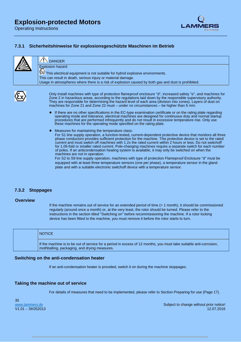
Explosion-protected Motors Operating Instructions 7.3.1 Sicherheitshinweise für explosionsgeschützte Maschinen im Betrieb
DANGER Explosion hazard
This electrical equipment is not suitable for hybrid explosive environments.
This can result in death, serious injury or material damage.
Usage in atmospheres where there is a risk of explosion caused by both gas and dust is prohibited.
Only install machines with type of protection flameproof enclosure "d", increased safety "e", and machines for Zone 2 in hazardous areas, according to the regulations laid down by the responsible supervisory authority. They are responsible for determining the hazard level of each area (division into zones). Layers of dust on machines for Zone 21 and Zone 22 must – under no circumstances – be higher than 5 mm.
● If there are no other specifications in the EC-type examination certificate or on the rating plate regarding
operating mode and tolerance, electrical machines are designed for continuous duty and normal startup procedures that are performed infrequently and do not result in excessive temperature rise. Only use these machines for the operating mode specified on the rating plate.
● Measures for maintaining the temperature class:
For S1 line supply operation, a function-tested, current-dependent protective device that monitors all three phase conductors provides sufficient protection for the machine. This protective device is set to the rated current and must switch off machines with 1.2x the rated current within 2 hours or less. Do not switchoff for 1.05-fold or smaller rated current. Pole-changing machines require a separate switch for each number of poles. If an anticondensation heating system is available, it may only be switched on when the machines are not in operation. For S2 to S9 line supply operation, machines with type of protection Flameproof Enclosure "d" must be
equipped with at least three temperature sensors (one per phase), a temperature sensor in the gland
plate and with a suitable electronic switchoff device with a temperature sensor.
7.3.2 Stoppages
Overview If the machine remains out of service for an extended period of time (> 1 month), it should be commissioned
regularly (around once a month) or, at the very least, the rotor should be turned. Please refer to the
instructions in the section titled "Switching on" before recommissioning the machine. If a rotor locking
device has been fitted to the machine, you must remove it before the rotor starts to turn.
NOTICE
If the machine is to be out of service for a period in excess of 12 months, you must take suitable anti-corrosion, mothballing, packaging, and drying measures.
Switching on the anti-condensation heater
If an anti-condensation heater is provided, switch it on during the machine stoppages.
Taking the machine out of service
For details of measures that need to be implemented, please refer to Section Preparing for use (Page 17). 35
www.lammers.de Subject to change without prior notice! V1.01 – SK052013 12.07.2016

75 of 86
Explosion-protected Motors Operating Instructions
Lubricating before recommissioning
NOTICE
The machine must be relubricated during commissioning if it has been out of service for more than 1 year, in order to ensure that the grease is distributed throughout the bearings. The shaft must rotate for the grease to be distributed. Please observe the information on the lubricant plate if carrying out relubrication using relubrication equipment. See also the section titled "Application planning - Bearing lifetime".
7.3.3 Fault tables
Overview
Note
Before rectifying any faults, please read the information in the section titled Safety notes (Page 7).
Note In the event that electrical faults occur while the machine is being operated with a converter, please also
refer to the operating instructions for the frequency converter.
The tables below list general faults caused by mechanical and electrical influences.
Table 7-2 Fault table, electrical causes
Electrical fault characteristics
↓ Machine will not start up
↓ Machine starts up reluctantly
↓ Rumbling noise during startup
↓ Rumbling noise during operation
↓ Overheating during no-load operation
↓ Overheating when under load
↓ Overheating of individual winding sections
Possible causes of faults Remedial measures1)
X X X X Overload Reduce load
X Interruption of a phase in the supply line. Check switches and supply lines
X X X X X Interruption of a phase in the supply line Check switches and supply lines after switching on
X X Supply voltage too low, frequency too high Check power supply conditions
X X X X Supply voltage too high, frequency too low Check power supply conditions
X X X X Stator winding incorrectly connected Check winding connections
36 www.lammers.de Subject to change without prior notice!
V1.01 – SK052013 12.07.2016
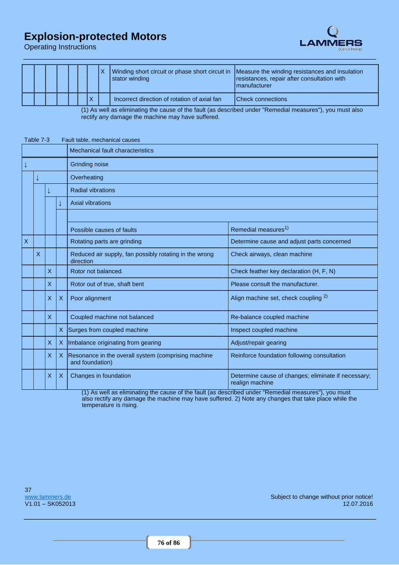
76 of 86
Explosion-protected Motors Operating Instructions
X Winding short circuit or phase short circuit in Measure the winding resistances and insulation stator winding resistances, repair after consultation with manufacturer
X Incorrect direction of rotation of axial fan Check connections
(1) As well as eliminating the cause of the fault (as described under "Remedial measures"), you must also
rectify any damage the machine may have suffered.
Table 7-3 Fault table, mechanical causes
Mechanical fault characteristics
↓ Grinding noise
↓ Overheating
↓ Radial vibrations
↓ Axial vibrations
Possible causes of faults Remedial measures1)
X Rotating parts are grinding Determine cause and adjust parts concerned
X Reduced air supply, fan possibly rotating in the wrong Check airways, clean machine direction
X Rotor not balanced. Check feather key declaration (H, F, N)
X Rotor out of true, shaft bent Please consult the manufacturer.
X X Poor alignment Align machine set, check coupling 2)
X Coupled machine not balanced Re-balance coupled machine
X Surges from coupled machine Inspect coupled machine
X X Imbalance originating from gearing Adjust/repair gearing
X X Resonance in the overall system (comprising machine Reinforce foundation following consultation and foundation)
X X Changes in foundation Determine cause of changes; eliminate if necessary; realign machine
(1) As well as eliminating the cause of the fault (as described under "Remedial measures"), you must also rectify any damage the machine may have suffered. 2) Note any changes that take place while the temperature is rising.
37
www.lammers.de Subject to change without prior notice! V1.01 – SK052013 12.07.2016

77 of 86
Explosion-protected Motors Operating Instructions
7.3.4 Marking explosion proofmachines Table 7-4 Zone 1 with Ex de IIC Gb type of protection (flameproof enclosure)
158 II 2 G Ex d e IIC T4 Gb
Table 7-5 Zone 1 with Ex e IIC Gb type of protection (increased safety "e")
II 3 G Ex nA IIC T3 Gc
Table 7-6 Zone 2 with type of protection Ex nA IIC Gc, (non sparking)
II 3 G Ex nA IIC T3 Gc
Table 7-7 Zone 21
158 II 2 D Ex t IIIC T125°C Db
Table 7-8 Zone 22
II 3 D Ex t IIIB T125°C Dc
38 www.lammers.de Subject to change without prior notice! V1.01 – SK052013 12.07.2016

78 of 86
Explosion-protected Motors Operating Instructions
8 Maintenance 8.1 Preparation and notes
WARNING Safety instructions
● Before starting work on the machines, make sure that the plant or system has been disconnected in a manner that
is compliant with the appropriate specifications and regulations. ● In addition to the main currents, make sure that supplementary and auxiliary circuits, particularly in heating
devices, are also disconnected. ● Certain parts of the machine may reach temperatures above 50 °C. Physical contact with the machine could result
in burn injuries! Check the temperature of parts before touching them. ● When carrying out cleaning using compressed air, make sure that appropriate methods of extracting fumes are in
place and that personal protective gear such as gloves, goggles, face masks, or similar are worn. If you are using chemical cleaning agents, observe the instructions and any warnings provided in the relevant safety data sheet. Chemical agents must be compatible with the machine's components, especially if these contain plastics.
Note
Operation characteristics can vary widely. For this reason, only general maintenance intervals can
be specified here.
Preparation and notes for explosion protected machine ● Only have the machines repaired in authorized Siemens workshops!
● For machines intended for use in hazardous areas, only have modifications, repairs and overhaul work carried out by appropriately qualified personnel. It is imperative that you observe the regulations according to EN / IEC 60079-19 !
● When making changes or performing repair or overhauling work on machines intended for use with
combustible dust, please observe the regulations laid down by EN / IEC 60079-17!
39
www.lammers.de Subject to change without prior notice! V1.01 – SK052013 12.07.2016

79 of 86
Explosion-protected Motors Operating Instructions
8.1.1 Repainting
WARNING Explosion danger caused by incorrect painting The paint coat can become electrostatically charged where there is a thick coat. Electrostatic discharges can occur. There is a risk of explosion if potentially explosive mixtures are also present at this moment. This can result in death, serious injury or material damage.
You must comply with one of the following requirements when you repaint painted surfaces: ● Limit the total paint coating thickness in accordance with the explosion protection group:– IIA, IIB: Total
paint coating thickness ≤ 2 mm
– IIC: Overall coating thickness ≤ 0.330 mm for motors of group II (gas) ● Limit the surface
resistance of the paint used: – IIA, IIB, IIC, III: Surface resistance ≤ 1 GΩ for motors of groups II and III (gas and dust)
● Breakdown voltage ≤ 4 kV for explosion group III (dust only)
● An overall coating thickness of > 120 µm is inadmissible for processes which generate strong charges.
8.2 Regreasing (optional) General
As a standard feature, the machines have rolling-contact bearings which are permanently lubricated with grease (UNIREX N3, made by ESSO). A regreasing device is possible as an option. In this case, you can find information about relubrication intervals, quantities and types of grease, and, if required, additional data on the rating plate or lubricant plate.
Note
Do not mix different types of grease!
Prolonged storage periods reduce the useful life of the bearing grease. Check the condition of the grease if the equipment has been in storage for more than 12 months. If the grease is found to have lost oil content or to be contaminated, the machine must be immediately
8.3 Cleaning relubricated before commissioning. For information on permanently-greased bearings, please refer to
the section titled Bearings (Page 54).
Note Regreasing 1. Clean the grease nipples at the drive end and non-drive end.
2. Press in the type and quantity of grease specified (see rating/lubricant plate data).
● Please observe the information on the rating and lubricant plates. ● Regreasing should be carried out when the machine is running (max. 3600 rpm)!
The bearing temperature rises sharply at first, then drops to the normal value again when the excess
grease is displaced out of the bearing.
40 www.lammers.de Subject to change without prior notice! V1.01 – SK052013 12.07.2016

80 of 86
Explosion-protected Motors Operating Instructions
8.3 Cleaning 8.3.1 Safety instructions for cleaning
Cleaning To ensure problem-free machine cooling, the air ducts (ventilation grilles, channels, cooling fins, tubes)
must be free of pollution.
DANGER Explosion hazard
It is forbidden to clean the machine in an explosive atmosphere! This can result in death,
serious injury or material damage. Surfaces can become statically charged and discharge to ignite potentially explosive atmospheres.
8.3.2 Cleaning
Cleaining the greasing channels and used grease chambers
The used grease collects outside each bearing in the used grease chamber of the outer bearing cap. When
replacing bearings, remove the used grease.
Note You have to separate the active parts of the bearings to replace the grease that is in the greasing channel.
Cleaning the cooling air passages
Regularly clean the cooling air passages through which the ambient air flows, e.g. using dry compressed air.
Note Never direct compressed air in the direction of the shaft outlet or machine openings.
In the case of machines with textile fan covers, regularly remove fluff balls, fabric remnants, and similar
types of contamination (particularly at the air passage opening between the fan cover and cooling fins of the
machine enclosure) to ensure that the cooling air can flow without obstruction.
Note The frequency of the cleaning intervals depends on the local degree of contamination.
WARNING Particularly when carrying out cleaning using compressed air, make sure you use suitable extraction equipment and wear personal protective gear (safety goggles, respiratory filter, etc.).
41
www.lammers.de Subject to change without prior notice! V1.01 – SK052013 12.07.2016

81 of 86
Explosion-protected Motors Operating Instructions
8.4 Bearings
Take the bearing used up to frame size 90 only for special versions, and generally for frame size 100
and higher from the rating plate.
Bearing lifetime Prolonged storage periods reduce the useful lifetime of the bearing grease. In the case of
permanently lubricated bearings, this leads to a shorter bearing lifetime. Bearing or grease replacement is recommended after a storage time of 12 months, for longer than four
years, replace the bearings or grease.
8.5 Dismantling
Replacing bearings
Recommended interval after which bearings are to be replaced under normal operating conditions:
Table 8-1 Bearing replacement intervals
Ambient temperature Principle of operation Bearing replacement intervals
40° C Horizontal coupling operation 40 000 h
40° C With axial and radial forces 20 000 h
Note
Special operating conditions Examples of factors that can reduce operating hours are vertical machine installation, high vibrational
and impact loads, frequent reversing, higher ambient temperature, higher speeds, etc.
Note ● Do not reuse bearings that have been removed.
● Remove any existing contaminated old grease from the bearing shield!
● Replace old grease with new grease!
● Replace the shaft seals when the bearings are replaced.
● Lightly grease the contact surfaces of the sealing lips!
8.4.1 Replacing bearings in explosion-proofmachines
● When changing the bearings, renew the sealing rings and only use original Siemens spare parts.
● When installing the sealing rings for the motor series 1LA., 1MA.06. to 20., 1MJ6., fill completely the space in the sealing ring and in the end shield hub with a suitable type of grease.
42 www.lammers.de Subject to change without prior notice! V1.01 – SK052013 12.07.2016

82 of 86
Explosion-protected Motors Operating Instructions
8.5 Dismantling
Note Before commencing disassembly, you should mark how each of the fastening elements has been
assigned, as well as how internal connections are arranged, for re-assembly purposes.
Fan
Take care not to damage the snapping mechanisms on fans that are equipped with these. To ensure this, the
fans should be heated to a temperature of approximately 50 °C around the area of the hub. If any damage is
caused, request new parts.
Fancover 1. Carefully lever the snap openings on the cover out of the snap-in lugs one after the other; do not apply the
lever directly under the web (risk of breakage). 2. Do not damage the snap mechanisms. If any damage is caused, request new parts.
Canopy, incremental encoder under the canopy Loosen the fixing screws on the external surface of the protective cover. Under no circumstances should the spacing bolts or the mounting bracket be disassembled or forcibly
separated from each other or the cover. Forcibly removing or separating can destroy the distance bolts,
the connecting elements of the mounting bracket or the fan cover.
8.6 Reassembly
Note Avoid damaging the windings protruding out of the stator enclosure when fitting the end shield.
8.6.1 Assemly
● Apply Fluid-D to the centering edge.
● Check the terminal box seals and if required, replace.
● Repair any damage to the paint (also on screws/bolts).
● Take the necessary measures to ensure compliance with the applicable degree of protection.
● Do not forget the foam cover in the cable entry (seal all holes completely and prevent cables from touching any sharp edges).
For flameproof machines, apply just a small amount of acid-free, non-resinous grease to the centering
edges (e.g. Renolit H 442 supplied by Fuchs). Do not use any sealing agents. 43
www.lammers.de Subject to change without prior notice! V1.01 – SK052013 12.07.2016
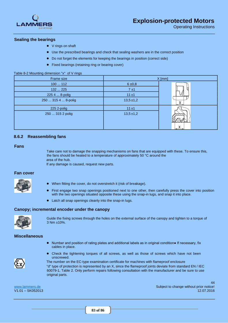
83 of 86
Explosion-protected Motors Operating Instructions
Sealing the bearings
● V rings on shaft
● Use the prescribed bearings and check that sealing washers are in the correct position
● Do not forget the elements for keeping the bearings in position (correct side)
● Fixed bearings (retaining ring or bearing cover) Table 8-2 Mounting dimension "x" of V rings
Frame size X [mm]
100 ... 112 6 ±0,8
132 ... 225 7 ±1
225 4 ... 8-polig 11 ±1
250 ... 315 4 ... 8-polig 13,5 ±1,2
225 2-polig 11 ±1
250 ... 315 2 polig 13,5 ±1,2
8.6.2 Reassembling fans
Fans Take care not to damage the snapping mechanisms on fans that are equipped with these. To ensure this,
the fans should be heated to a temperature of approximately 50 °C around the area of the hub. If any damage is caused, request new parts.
Fan cover
● When fitting the cover, do not overstretch it (risk of breakage).
● First engage two snap openings positioned next to one other, then carefully press the cover into position with the two openings situated opposite these using the snap-in lugs, and snap it into place.
● Latch all snap openings cleanly into the snap-in lugs.
Canopy; incremental encoder under the canopy
Guide the fixing screws through the holes on the external surface of the canopy and tighten to a torque of
3 Nm ±10%.
Miscellaneous
● Number and position of rating plates and additional labels as in original condition● If necessary, fix cables in place.
● Check the tightening torques of all screws, as well as those of screws which have not been
unscrewed. The number on the EC-type examination certificate for machines with flameproof enclosure "d" type of protection is represented by an X, since the flameproof joints deviate from standard EN / IEC
60079-1, Table 2. Only perform repairs following consultation with the manufacturer and be sure to use
original parts.
44 www.lammers.de Subject to change without prior notice! V1.01 – SK052013 12.07.2016
84 of 86
Explosion-protected Motors Operating Instructions
9 Spare parts
General In addition to the exact part designation, please specify the machine type and the serial
number in all orders for spare parts and repair parts.
Technische Anfragen oder zusätzliche Informationen Bei technischen Fragen oder benötigten Informationen, bitte
kontaktieren Sie Clemens Lammers GmbH & Co. KG Folgede Informationen werden benötigt
● Motortyp (Typenschild) ● Seriennummer (Typenschild) ● Auftragsnummer
Clemens Lammers GmbH & Co. KG
Offenbergweg 17 | D-48432 Rheine
Postfach 1738 | D-48407 Rheine Tel. 0049 (0) 5971 / 80 11-0 Fax 0049 (0) 5971 / 80 11-4011 Home: www.lammers.de | Email: [email protected]
45
www.lammers.de Subject to change without prior notice!
V1.01 – SK052013 12.07.2016

85 of 86
CERTIFICATE OF CONFORMANCE

86 of 86
DATA SHEETS