mega operating instructions
TRANSCRIPT

MEGA
THANK YOU CUSTOMER
You are a proud owner of a MEGA pump
The nameplates punched on the pump shows thePump type (series & size), serial no. (works order no. ) and main operating data.
Please quote the above information in all queries, repeat orders and particularly when ordering spares.
&

MEGA
Sr. no. Description Page no.
CONTENTS
1 General 11.1 Handling 1
2 Installation(on site) 12.1 Foundation 12.2 Mounting 12.3 Aligning Pump / motor 12.4 Connecting the piping 22.4.1 Auxillary connections 32.4.2 Vacuum balance line 32.5 Coupling guard 32.6 Final check 3
3 Commissioning / start-up,shutdown 3
3.1 Preparations 33.1.1 Procedure 33.1.2 Shaft seal 33.1.2.1 Stuffing box 43.1.2.2 Packing the stuffing box 43.1.3 Priming & associated checks 43.1.4 Checking the direction of rotation 43.2 Start-up 43.3 Shutdown 4
4 Maintenance & lubrication 54.1 Suprevision & operation 54.2 Lubrication & lubricant change 54.2.1 Grease change 54.2.2 Oil change (if applicable) 5
5 Dismantling 55.1 General 55.2 Dismantling 55.3 Dismantling the bearing unit 65.4 Removal of mechanical seal 6
6 Reassembly 66.1 Pump 66.2 Replacement of wearing rings 66.3 Replacing of bearings 76.3.1 Deep groove ball bearings &
lubricant fill 76.4 Mecahnical seal 76.4.1 Conversion kit 76.5 Stuffing box compartment 7
7 Spare parts 77.1 Ordering spare parts 7
8 Interchangeability of components& recommended spares for 2 yearsof continuous operation 8
9 Sectional drawing 99.1 List of components 10
10 Faults- Cause & remedy 11 & 12

MEGA
1
1 GeneralYour centrifugal pumps will only give you completely troublefree and satisfactory service on condition that it is installed withdue care and properly maintained. It is absolutely essential thatthe instructions contained in this manual be strictly observedand that the pumps are not operated under conditions whichdiffer from those specified under our `Operating Conditions'.This operating instruction manual dose not take any accountof any safety regulations which may apply to the installationsite, and the site engineer & the site operator is responsible fornotifying our erection staff of any such regulations and seeingthat they are complied with.
The type series, pump sizes, main operating data and theworks order number are all stamped on the name plate affixedto the pump. Please make sure to quote this information everytime you write to us in respect of queries, repeat orders andmore particularly when ordering spare parts.
In case you are using the pump for applications other thanwater, please ensure that you have a specific confirmationfrom the dealer or KSB.
1.1 HandlingWhen handling the complete pumpset or bare pump attachropes to the pump and motor as shown (not through themotor eyebolt).
Fig. 4 : Aligning a coupling
2.3 Aligning pump / motorAfter the baseplate has been fixed in position carefully checkthe coupling and if necessary, realign the pumpset (with themotor). Prior to checking the alignment and /or aligning, loosensupporting foot (183) and tighten again without transmittingany strain. Please check the alignment of pump motor andcoupling even though they are supplied ready mounted onbaseframe.
The pumpset to be aligned radially and axially within 0.1 mmby installing dial indicaters as shown in fig. no. 4 and withoutpipe connection.The gap between the two coupling halvesmust be the same at all points (minimum 3 points) on thecircumference; this can be measured using calipers or afeeler gauge.
The alignment should be carried with & without pipeconnections and should be within limits. For liquids handlingmore than 1050C; cold alignment & hot alignment both shouldbe carried out on pumpset.
Fig. no. 3 : Fitting shims
Uniformly tighten up securing means.Baseplates have to begrouted with non-shrinking mortar up to the upper edge of theframe after having been fixed in position.
2 Installation (on site)
2.1 FoundationMake sure the concrete foundation has set before mountingthe pumpset. The surface of the foundation must be completelyhorizontal and perfectly flat.
2.2 MountingPosition the pumpset on the foundation and level using aprecision spirit level on the discharge nozzle of pump. Ensurethe gap between the two coupling halves is as given on thegeneral arrangement drawing. Always fit shims to the left andright of the anchor bolts, between the baseplate / foundationframe and the foundation. If the shims are more than 800 mmapart, position extra shims equidistant between them. Allshims must seat perfectly flush with the baseplate / frame.
Fig. no. 2 : Pump & motor on a common baseframe
Fig. no. 1 : Bare pump

MEGA
2
Fig.5c : Suction pit below the pump, suction pipe with rising slopetowards pump.
Fig. 5b : Suction pit above the pump, suction pipe with downwardslope towards pump.
Before commissioning a new installation, thoroughly clean,flush and blow through all vessels, piping & connections.Welding beads, scale and other impurities get dislodged aftera certain period of operation; it is necessary to fit a strainer inthe suction line to prevent these entering the pump. The totalcross section of the holes in the strainer should be three timesthe cross section of the piping in order to avoid excessivepressure loss across the strainer due to clogging.
The conical strainer consists of a coarse strainer fronted by afine strainer with a 2.0 mm mesh and 0.5 mm diameter wire,made of corrosion resistant material, (i.e. Stainless Steel) ref.fig. 6.
1 Suction line2 Strainer holder3 Fine strainer4 Coarse strainer5 Pump suction nozzle
Fig. 6 : Conical strainer for suction line
Fig. 5d : Suction pipe connections
2.4 Connecting the pipingNever use the pump itself as an anchorage for the piping.Suction lift lines should be laid with a rising slope towardsthe pump and suction head line with a downward slopetowards the pump.(Fig. 5c, 5b, 5d). Any thermal expansion ofthe piping (due to high temperatures) must be compensatedby suitable means, so as not to impose any additional loadon the pump.
The pipelines should be anchored in close proximity to thepump and should be connected to the latter withouttransmitting any stress or strain, nor should weight of thepiping be loaded on to the pump.
Fig. 5a - The nominal sizes of the pipelines should be atleastequal to the nominal sizes of the pump nozzles.(fig. 5a, 5d)or as recommended in the performance curve. Please askdealer or KSB incase the nominal sizes are not conveyed.
We recommend the incorporation of suitable pressure gaugesclose to suction & discharge flanges and also check valvesor non-return valves and isolating valves in the system,depending on the type of the installation and pump.
Fig.5a : Piping & supporting of piping

MEGA
3
2.4.2 Vacuum balance lineIf the pump has to pump a liquid out of vessel under vacuum,it is advisable to install a vacuum balance-line. This lineshould have a nominal size of 25 mm at least. It should bearranged to lead back into the vacuum vessel at a point abovethe permissible liquid level. An additional line starting at thepump discharge-nozzle facilitates venting of the pump beforestart up. The vacuum tight isolating valve E in the connectingline should be closed after the venting procedure and shouldremain closed while the pump is running. The main isolatingvalve C in the vacuum balance line must remain open at alltimes when the pump is running and should only be closedwhen the pump is shut down.
3 Commissioning / startup, shutdown3.1 PreparationsGrease lubricated bearings : Grease lubricated bearingsare pre-packed with grease for life time. No greasing isrequired at site. Do not fill oil for grease lubricated bearings.
Oil lubricated bearings : The bearing bracket should befilled with oil of the types & specifications as mentioned in4.2.2.
2.5 Coupling guardIn compliance with the accident prevention regulations, thepump may only be operated if it is fitted with a coupling guard.If the customer states specifically that the coupling guard isnot to be supplied by us, it must be provided by the customer.
2.6 Final checkRecheck alignment as described in 2.3It must be possible to rotate the coupling easily by hand.Check the integrity of all connections.
Fig. no. 9 : Oil fill level
3.1.1 ProcedurePull out dipstick. Fill in oil through the hole left by the dipstick(fig.no. 9 & 10). After a short time check whether the oil levelin the bearing bracket has dropped; then put more oil up tomarking on the dipstick. Fix the dipstick back in.
3.1.2 Shaft SealThe shaft is sealed at its exit though the casing by a soft packedstuffing box or a mechanical seal. Changeover from glandpacking execution to mechanical seal & viceversa is possibleby using conversion kit. For details refer dealer or KSB.
Conn. Conn. Size Code type A-30 A-40 A-50 A-601M1 Pressure guage NPT 3/8" 3/8" 1/2" 1/2"1M2 Pressure guage NPT 3/8" 3/8" 1/2" 1/2"3M Pressure guage NPT 3/8" 3/8" 1/2" 1/2"6D Casing drain NPT 3/8" 3/8" 1/2" 1/2"7E Cooling inlet NPT 1/2" 1/2" 1/2" 1/2"7S Cooling outlet NPT 1/2" 1/2" 1/2" 1/2"8D Drain (leakage) NPT 3/8" 3/8" 3/4" 3/4"10E External sealing in NPT 1/2" 1/2" 1/2" 1/2"10S External sealing out NPT 1/2" 1/2" 1/2" 1/2"13E* Oil filling / Dip stick 13D* Oil drain G 1/4" 1/4" 1/4" 1/4"
Ø 20 mm
Description
Table no. 1
Fig. 8 : Suction line and vacuum balance line.
A. Main isolation valve, suction E. Vaccum tight isolationB. Vacuum balance line valveR. Non- return valve V. Vacuum vesselC. Isolation valve Z. Intermediate flange
2.4.1 Auxiliary connectionsThe size and location (connection code) of all auxiliaryconnections are shown in the fig. no.7 & table no. 1.
Fig. no. 7 : Auxillary connections of pump
* MEGA pumps are supplied with grease lubricated bearingsas a standard supply. If in doubt of type of bearings suppliedplease check with the dealer or KSB.

MEGA
4
Cutting the gland packing
The following packing rings are then inserted into the packingcompartment one by one, making sure that the butt joint ofeach ring is offset by 900 approx. in relation to the butt joint ofthe preceding ring. The individual rings are pushed home intothe packing compartment with the aid of the stuffing box gland(452). The packing rings should only be pressed lightly againstone another. They should be inser ted in the packingcompartment in such a way that a clear gap of 6 to 8 mm isleft at the outer end of the compartment for the positive guideof the stuffing box gland (452).
The inserted packing rings should then be compressedmoderately with the aid of the stuffing box gland (452) and thenuts (920). Then the nuts (920) should be slackened again byone to two complete turns, and thereafter tightened lightly byhand. The correct and even seating of the stuffing box gland(452) should be checked when the pump is subjected to suctionpressure, by inserting a feeler gauge between the stuffing boxgland (452) and the shaft protection sleeve (524).
A lantern ring (458) is also inserted in the packingcompartment, at the position shown in the cross-sectionaldrawing. The lantern ring must register beneath the drilledhole in the discharge cover (163), to enable the sealing liquidto enter. The pressure of the liquid should be 1 to 4 bar abovethe pressure existing in the packing compartment of the stuffingbox.
The packing of the stuffing box should be carried out withgreat care, to avoid an excessively high radial pressing forceof the packing rings against the shaft protection sleeve, whichmight damage the latter. If the shaft protection sleeve is scoredor grooved, even a new packing cannot be expected to lastvery long in service.
A newly packed stuffing box should leak profusely at first. Ifthis leakage does not cease of its own after a relatively shortperiod of operation, the nuts on the stuffing box (452) glandshould be tightened slowly and evenly while the pump isrunning, until the stuffing box only drips slightly. Make surethat the stuffing box gland (452) is tightened evenly and not askew, as otherwise the shaft protection sleeve (524) might bedamaged.
If the newly packed stuffing box starts to emit smoke when thepump is started up for the first time, the pump should beswitched off. If the smoking persists after the pump has beenstarted up again and operated several times in succession,the nuts on the gland should be slackened slightly, or thestuffing box should be inspected if necessary.
3.1.3 Priming & associated checksVent and prime the pump and suction line before startup. Theshutoff valve in the suction line must be completely open.
(Open the shutoff valve in the vacuum line; if fitted and closedthe vacuum tight shutoff valve “E”; fig.no. 8).
3.1.4 Checking the direction of rotation
The direction of rotation of the prime mover must match withthe arrow on the pump. Check this by switching the motor onand immediately switching it off again.Mount the coupling guard.
3.2 Start-upStart the pump against a closed discharge valve only. Oncethe pump has reached full speed, slowly open the dischargevalve to set the duty point flow indicated on the name plate.
After the pump has reached its working temperature and/ or ifleakage occurs, tighten bolts (901.01) with the pumpdisconnected / switched off.
3.3 ShutdownClose the discharge isolating valve.The discharge isolating valve can remain open if the dischargeline is fitted with a non-return device on condition there isback-pressure.
Switch off the motor, making sure the pump set runs downsmoothly and evenly to a stand still.If the pumpset is to remain out of service for long periods,close the isolating valve in the suction line and close allconnections.
If there is danger of freezing and/or if the pump is to be out ofservice for long period, then the pump must be drained orotherwise protect it against freezing.
3.1.2.1. Stuffing BoxSoft-packed stuffing box reduce the flow of leakage liquid atthe clearance gap between casing cover and shaft protectionsleeve when the pressure inside the pump is higher thanatmospheric. Conversely, on pumps which operate on suctionlift pressure, the soft-packed stuffing box prevents the ingressof air into the pump. Sealing is effected by means of softpackings arranged in a number of rings in the annular spacebetween the discharge cover (163) and the shaft protectionsleeve (524) and lightly compressed by the stuffing box gland(452).
3.1.2.2 Re-Packing the Stuffing Boxes
Caution :The pump is despatched from our Works with the stuffing boxpacked.
Before repacking, thoroughly clean stuffing box gland (452),packing compartment and shaft protection sleeve (524).
Cut the packing ring to correct length and ends at 45º. Ensurethat the packing rings ends come into contact with one anotheron fitment. (See below "cutting the gland packing")
If the packing rings are either too long or too short, the stuffingbox will not be able to perform its function properly. In the caseof asbestos-graphite packing material, the rubbing faces ofthe individual rings should be lightly coated with MOLYKOTEbefore insertion in the packing compartment. The first packingring is then inserted and pushed home into the compartmentwith aid of the stuffing box gland (452).

MEGA
5
Fig. no. 10 : Oil lubrication
Procedure : Remove the drain plug (903.06) and drain offthe oil. When the bearing bracket is empty, refit the drain plug& refill the bearing bracket with oil from vent plug hole. Checkoil level with dipstick (fig. no. 9).
5 Dismantling5.1 GeneralBefore dismantling, make sure the motor is disconnectedfrom the power supply and cannot be switched on accidentally.The suction and discharge shutoff valves must be closed.The pump casing must have cooled down to ambienttemperature. The pump casing must be empty and not underpressure.
Fig. no. 11 : Dismantling the pumpset
For coupling without spacer / intermediate sleeve:
1. Disconnect motor from power supply.
2. Remove discharge and suction branch from pipe line.
3. Uncouple pump and motor.
4. Loosen and remove motor form baseplate.
5. Remove supporting foot (183) from the baseplate andloosen bolts (901.01) on discharge cover. Refer fig.no.11.
6. Pull out bearing bracket with discharge cover and completerotor (assembled unit).
(With larger pumps, suspend or support bearing bracket toprevent the rotating assembly from falling over.)
For coupling with spacer/intermediate sleeve
During dismantling, the volute casing can remain on thebaseplate and in the pipeline.
1. Remove spacer/intermediate sleeve of the coupling.
2. Remove supporting foot (183) from the baseplate andloosen bolts (901.01) on discharge cover. Refer fig.no.11 &Cross sectional drawing.
3. Pull out bearing bracket with discharge cover and completerotor (assembled unit).
If the pump has been in operation for a long time some partsmay be difficult to remove. In this case use a brand namepenetrating oil or suitable pull-off device.
Under no circumstances use force!
Fig. no. 12 : Removal of impeller from pump shaft
5.2 DismantlingProcedure :
1. Disconnect from power supply.
2. For oil-lubricated pumps drain-off the oil as described in 4.2.2.
3. Detach all auxiliary supply pipe lines.
4. Remove coupling guard.
5. Remove coupling half from the pump shaft. Refer fig.no.11
4 Maintenance and lubrication4.1 Supervision and operationThe pump must run quietly and evenly at all times.The pump must never run dry.The bearing temperature may be allowed 500C above roomtemperature, but must not exceed 800C(measured at theoutside of the bearing housing).Do not run the pump for a long period against a closeddischarge valve.Pumps with mechanical seals experience minor or invisible(vapour) leakage. The seal is maintenance-free.Stand-by pumps should be started up and immediately shutdown again once a week to keep them operational.Flexible parts of coupling which shows signs of wear shouldbe replaced in good time.
4.2 Lubrication and lubricant change4.2.1 Grease changeThe anti-friction bearings are prepacked with grease by themanufacturer; no necessity of greasing it for life time.
4.2.2 Oil change ( If applicable )The first oil change must be carried out after 300 hours ofoperation; all subsequent oil changes after 3000 hours. Thebearing bracket should be filled up to the mark with oil of anyone of the following types and specifications. For quantity;refer table no. 2 & 4.
Table no.2
Indian Oil : Servosystem 46
Hindustan Petroleum : Enclo 46
Bharat Petroleum : Bharat Hydrol 46
MEGA
6
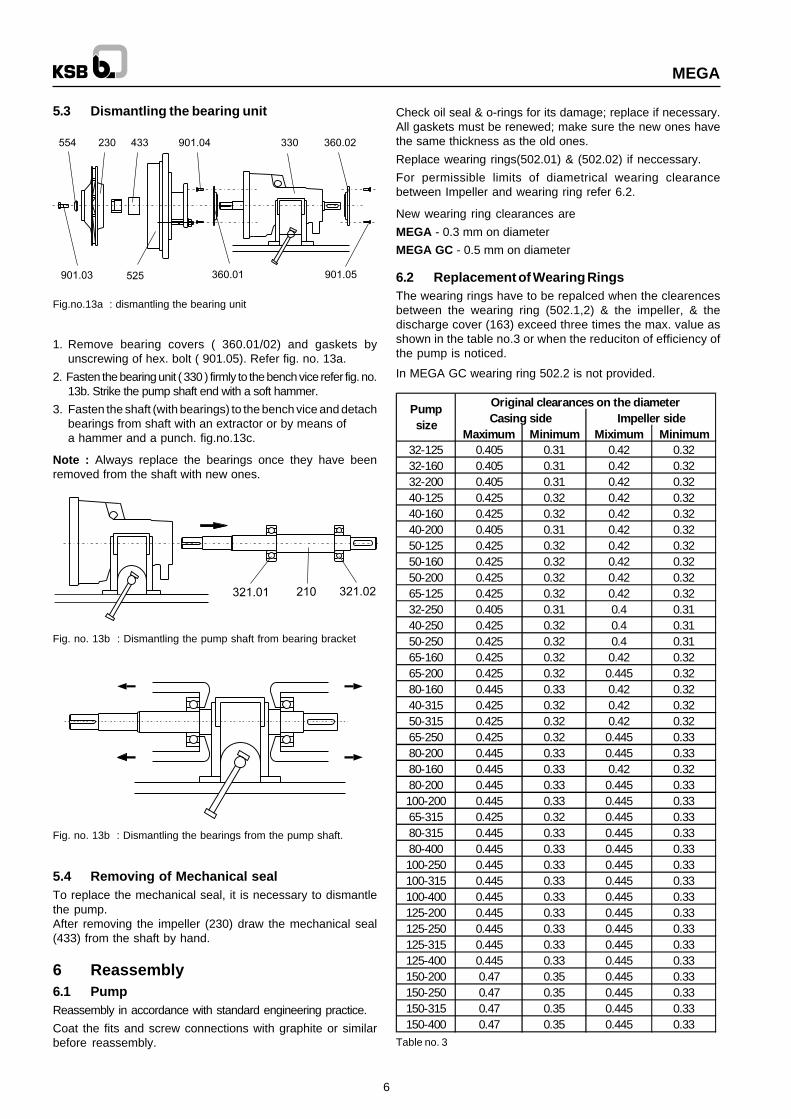
Table no. 3
Original clearances on the diameterCasing side Impeller side
Maximum Minimum Miximum Minimum32-125 0.405 0.31 0.42 0.3232-160 0.405 0.31 0.42 0.3232-200 0.405 0.31 0.42 0.3240-125 0.425 0.32 0.42 0.3240-160 0.425 0.32 0.42 0.3240-200 0.405 0.31 0.42 0.3250-125 0.425 0.32 0.42 0.3250-160 0.425 0.32 0.42 0.3250-200 0.425 0.32 0.42 0.3265-125 0.425 0.32 0.42 0.3232-250 0.405 0.31 0.4 0.3140-250 0.425 0.32 0.4 0.3150-250 0.425 0.32 0.4 0.3165-160 0.425 0.32 0.42 0.3265-200 0.425 0.32 0.445 0.3280-160 0.445 0.33 0.42 0.3240-315 0.425 0.32 0.42 0.3250-315 0.425 0.32 0.42 0.3265-250 0.425 0.32 0.445 0.3380-200 0.445 0.33 0.445 0.3380-160 0.445 0.33 0.42 0.3280-200 0.445 0.33 0.445 0.33100-200 0.445 0.33 0.445 0.3365-315 0.425 0.32 0.445 0.3380-315 0.445 0.33 0.445 0.3380-400 0.445 0.33 0.445 0.33100-250 0.445 0.33 0.445 0.33100-315 0.445 0.33 0.445 0.33100-400 0.445 0.33 0.445 0.33125-200 0.445 0.33 0.445 0.33125-250 0.445 0.33 0.445 0.33125-315 0.445 0.33 0.445 0.33125-400 0.445 0.33 0.445 0.33150-200 0.47 0.35 0.445 0.33150-250 0.47 0.35 0.445 0.33150-315 0.47 0.35 0.445 0.33150-400 0.47 0.35 0.445 0.33
Pump size
6.2 Replacement of Wearing RingsThe wearing rings have to be repalced when the clearencesbetween the wearing ring (502.1,2) & the impeller, & thedischarge cover (163) exceed three times the max. value asshown in the table no.3 or when the reduciton of efficiency ofthe pump is noticed.
In MEGA GC wearing ring 502.2 is not provided.
Check oil seal & o-rings for its damage; replace if necessary.All gaskets must be renewed; make sure the new ones havethe same thickness as the old ones.
Replace wearing rings(502.01) & (502.02) if neccessary.
For permissible limits of diametrical wearing clearancebetween Impeller and wearing ring refer 6.2.
New wearing ring clearances are
MEGA - 0.3 mm on diameter
MEGA GC - 0.5 mm on diameter
Fig. no. 13b : Dismantling the bearings from the pump shaft.
5.4 Removing of Mechanical sealTo replace the mechanical seal, it is necessary to dismantlethe pump.After removing the impeller (230) draw the mechanical seal(433) from the shaft by hand.
6 Reassembly6.1 PumpReassembly in accordance with standard engineering practice.
Coat the fits and screw connections with graphite or similarbefore reassembly.
5.3 Dismantling the bearing unit
Fig.no.13a : dismantling the bearing unit
1. Remove bearing covers ( 360.01/02) and gaskets byunscrewing of hex. bolt ( 901.05). Refer fig. no. 13a.
2. Fasten the bearing unit ( 330 ) firmly to the bench vice refer fig. no.13b. Strike the pump shaft end with a soft hammer.
3. Fasten the shaft (with bearings) to the bench vice and detachbearings from shaft with an extractor or by means ofa hammer and a punch. fig.no.13c.
Note : Always replace the bearings once they have beenremoved from the shaft with new ones.
Fig. no. 13b : Dismantling the pump shaft from bearing bracket

MEGA
Dimensions of packing compartment in mm
Table no.5
# See interchangeability of components for co-relation of shaft &pump sizes in table no. 6.
7 Spare parts7.1 Ordering spare partsWhen ordering spare parts please indicate the followinginformation which may be taken from the name plate of thepump. If the name plate is missing then check on the dischargeflange for serial/work order no. e.g. :
Type : MEGA 50-250
Serial/work order no. : 955 1234-1235
7
Bearing Grease packed Oil lubricationbracket Bearing no. Bearing no. Oil qty.in ltr.
A-30 6306 2Z C3 6306 C3 0.2
A-40 6308 2Z C3 6308 C3 0.35
A-50 6310 2Z C3 6310 C3 0.65
A-60 6312 2Z C3 6312 C3 0.65
Bearing Dimensionsbracket # d1 d2 l
A - 30 35 55 71A - 40 45 65 71A - 50 60 85 90.5A - 60 70 95 90.5
6.3.1 Deep groove ball bearing & lubricant fill(Only increase of oil lubricated bearings)
Table no. 4
6.4 Mechanical sealThe following points should be observed when mounting themechanical seal :Extreme care and cleanliness during assembly are theessential pre-requsites for the trouble-free operation of themechanical seal.The guard protecting the rubbing faces should only be removedbefore assembly takes place.When the stationary seal rings has been inserted, check itsplane parallelism in relation to the casing component.Before reassembly, clean the spacer sleeve (525). Checkshaft surface under mechanical seal area. Make sure thatthere are no scratches or grooves. If it is found then touch upscratches / grooves. If not possible then replace the shaft bynew ones.
Fig. no. 15 : Mechanical seal
6.4.1 Conversion kitParts required for changeover from gland packing tomechanical seal are :
1. Spacer sleeve (525)2. Mechanical seal (433)3. Seal cover (476)4. Studs & nuts5. Set of gaskets
6.5 Stuffing box compartment
Fig. no. 16 : Stuffing box compartment
6.3 Replacing of bearings1. Check the shaft ( 210 ) with its spacer sleeve (525) / or shaft
protection sleeve (524) (as applicable) for eccentricity,between centres. Maximum allowable eccentricity is 0.05mm.
2. Fasten the shaft (210) to the bench vice using soft polishsheets between the vice clamp jaws to avoid damage. Referfig.no.14.
3. Heat the bearings (321.01/02) in the oven about 800C max.and push it on to the shaft. Fig. no.14. Allow the bearings tocool down. Then tap it lightly against the shoulder usingsuitable pipe punch.
Fig. no. 14 : Mounting of bearings

MEGA
8 Interchangeability of components & recommended spares for 2 years of continuousoperation
8
Table no. 6 @ Only for cooled discharge covers
# Only for Oil lubricated bearings
Des
crip
tio
n
Vo
lute
cas
ing
Dis
char
ge
cove
r
Co
olin
g c
ove
r
Su
pp
ort
fo
ot
Sh
aft
Imp
elle
r
Dee
p g
roo
ve b
all b
eari
ng
Bea
rin
g b
rack
et
Bea
rin
g c
ove
r
Gas
ket
Gas
ket
Gas
ket
Gas
ket
O-r
ing
@
Oil
seal
Mec
han
ical
sea
l
Sea
l co
ver
Wea
rin
g r
ing
Imp
elle
r ri
ng
Sp
lash
rin
g
Sh
aft
Pro
t. S
leev
e / S
pac
er s
leev
e
Was
her
Dip
sti
ck#
/ ven
t p
lug
Hex
. bo
lt
Hex
. bo
lt
Key
Key
Par
t n
o.
102
163
165
183
210
230
321
330
360
400.
1
400.
2
400.
3
400.
4
412.
1/.2
421
433
471
502.
1
502.
2
507
524
/ 525
554
635
/ 913
901.
1
901.
03
940.
1
940.
2
32-125 2 1 1 1 1 2 1 1 1 1 1 1 1 1 1 1 1 1 13 1 1 1 1 1 1 1 132-160 4 1 1 2 1 3 1 1 1 1 1 1 1 1 1 1 1 1 13 1 1 1 1 1 1 1 1
32-200 6 2 1 3 1 4 1 1 1 1 1 1 1 1 1 1 1 1 13 1 1 1 1 1 1 1 1
40-125 7 1 1 1 1 5 1 1 1 1 1 1 1 1 1 1 1 2 13 1 1 1 1 1 1 1 140-160 8 1 1 2 1 6 1 1 1 1 1 1 1 1 1 1 1 2 13 1 1 1 1 1 1 1 140-200 9 2 1 3 1 7 1 1 1 1 1 1 1 1 1 1 1 3 13 1 1 1 1 1 1 1 150-125 10 1 1 2 1 8 1 1 1 1 1 1 1 1 1 1 1 4 13 1 1 1 1 1 1 1 150-160 11 1 1 3 1 9 1 1 1 1 1 1 1 1 1 1 1 4 13 1 1 1 1 1 1 1 150-200 12 2 1 3 1 10 1 1 1 1 1 1 1 1 1 1 1 4 13 1 1 1 1 1 1 1 165-125 13 1 1 3 1 11 1 1 1 1 1 1 1 1 1 1 1 5 13 1 1 1 1 1 1 1 1
32-250 15 3 2 4 2 12 2 2 2 2 2 2 2 2 2 2 2 1 3 2 2 2 1 2 2 2 240-250 16 3 2 4 2 13 2 2 2 2 2 2 2 2 2 2 2 2 3 2 2 2 1 2 2 2 240-315 21 8 2 6 2 18 2 2 2 2 2 2 2 2 2 2 2 2 14 2 2 2 1 3 2 2 250-250 17 3 2 4 2 14 2 2 2 2 2 2 2 2 2 2 2 4 3 2 2 2 1 2 2 2 250-315 22 8 2 7 2 19 2 2 2 2 2 2 2 2 2 2 2 5 14 2 2 2 1 3 2 2 265-160 18 4 2 5 2 15 2 2 2 2 2 2 2 2 2 2 2 5 15 2 2 2 1 2 2 2 265-200 19 5 2 4 2 16 2 2 2 2 2 2 2 2 2 2 2 5 15 2 2 2 1 2 2 2 265-250 A - 40 23 7 2 6 2 20 2 2 2 2 2 2 2 2 2 2 2 6 16 2 2 2 1 3 2 2 280-160 20 4 2 4 2 17 2 2 2 2 2 2 2 2 2 2 2 7 15 2 2 2 1 2 2 2 280-200 24 6 2 4 2 21 2 2 2 2 2 2 2 2 2 2 2 7 18 2 2 2 1 3 2 2 280-250 25 7 2 7 2 22 2 2 2 2 2 2 2 2 2 2 2 7 16 2 2 2 1 3 2 2 2100-160 26 6 2 6 2 23 2 2 2 2 2 2 2 2 2 2 2 8 18 2 2 2 1 3 2 2 2100-200 27 6 2 6 2 24 2 2 2 2 2 2 2 2 2 2 2 8 18 2 2 2 1 3 2 2 2
65-315 28 11 3 10 3 25 3 3 3 3 3 3 3 3 3 3 3 6 17 3 3 3 1 4 3 3 380-315 29 11 3 8 3 26 3 3 3 3 3 3 3 3 3 3 3 7 17 3 3 3 1 4 3 3 380-400 30 12 3 9 3 27 3 3 3 3 3 3 3 3 3 3 3 9 10 3 3 3 1 4 3 3 3100-250 31 10 3 10 3 28 3 3 3 3 3 3 3 3 3 3 3 8 10 3 3 3 1 4 3 3 3100-315 32 11 3 8 3 29 3 3 3 3 3 3 3 3 3 3 3 8 17 3 3 3 1 4 3 3 3100-400 33 12 3 9 3 30 3 3 3 3 3 3 3 3 3 3 3 8 10 3 3 3 1 4 3 3 3125-200 A - 50 34 9 3 8 3 31 3 3 3 3 3 3 3 3 3 3 3 10 10 3 3 3 1 4 3 3 3125-250 35 10 3 8 3 32 3 3 3 3 3 3 3 3 3 3 3 10 10 3 3 3 1 4 3 3 3125-315 36 11 3 9 3 33 3 3 3 3 3 3 3 3 3 3 3 10 17 3 3 3 1 4 3 3 3125-400 37 12 3 11 3 34 3 3 3 3 3 3 3 3 3 3 3 10 10 3 3 3 1 4 3 3 3150-200 38 9 3 9 3 35 3 3 3 3 3 3 3 3 3 3 3 11 10 3 3 3 1 4 3 3 3150-250 39 10 3 9 3 36 3 3 3 3 3 3 3 3 3 3 3 12 10 3 3 3 1 4 3 3 3
150-315 A - 60 40 13 4 12 4 37 4 4 4 4 4 4 4 4 4 4 4 12 10 4 4 4 1 5 4 4 4150-400 41 14 4 12 4 38 4 4 4 4 4 4 4 4 4 4 4 12 10 4 4 4 1 5 4 4 4
Recommended spare parts for 2 years of continuous operation
No. of pumps Quantity
Up to 3 nos. 1 1 1 - - 5 nos. each - - 2 1 - 2Up to 5 nos. 2 2 2 - - 8 nos. each - - 2 2 - 2Up to 7 nos. 2 3 3 - - 9 nos. each - - 3 3 - 3
Up to 10 nos. & above 30% 30% 30% 2 - 150% - - 50% 30% - 50%
Pump Size
Bea
rin
g b
rack
et
A - 30
MEGA
9
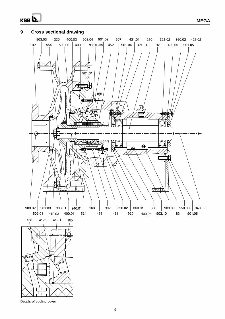
9 Cross sectional drawing
Details of cooling cover

MEGA
10
9.1 List of components
Part No. Description
102 Volute casing
163 Discharge cover
165 Cooling cover ( optional )
183 Support foot
210 Shaft
230 Impeller
321.01 / 02 Deep groove ball bearing
330 Bearing bracket
360.01 / 02 Bearing cover
400.01 - 05 Flat gasket
411.06 Gasket
412.01 / 02 O-ring ( for cooling cover )
412.03 O-ring
421.01 / 02 Oil seal
452 Gland cover
458 Lantern ring
461 Packing
502.01 / 02 Wearing ring - Casing / impeller
507 Splash ring
524 Shaft protection sleeve
550.01 / 03 Washer
554 Washer for impeller
901.01 - 06 Hex. head bolt
902 Stud
903.01 - 10 Hex. head plug
913 Vent plug
920 Hex. nut
940.01 - 02 Key

MEGA
10 Faults-cause & remedy
11
Pum
p de
liver
s in
suffi
cien
t liq
uid
Mot
or o
verlo
aded
Exc
essi
vely
hig
h pu
mp
disc
harg
e pr
essu
re
Bea
rings
ove
rhea
ting
Pum
p le
aks
Exc
essi
ve s
haft
seal
ing
leak
age
Rou
gh p
ump
runn
ing
Exc
essi
ve te
mpe
ratu
re r
ise
insi
de th
epu
mp
Cause Remedy 1)
• The pump generates excessively high differential pressure
Reset duty point
•Excessively high back pressure Check the plant for dirt. Fit larger
impeller 2)
• • •The pump and \ or piping are incompletely vented or primed.
Vent or prime the pump and piping completely
•Suction line or impeller clogged Remove the deposites in the pump and /
or piping
•Formation of air pockets in the piping Alter piping lyout. If necessary, fit a vent
valve
• • •NPSH avaliable is too low (on positive suction head installations)
Check the liquid level. Mount the pump at lower level. Open isolating valve in the suction line fully. Alter suction line, if the losses in the suction line are
•
Ingress of air on shaft seal Sealing liquid passage is clogged; clean it out. If necessary, arrange a sealing liquid supply from an outside source, or increase sealing liquid pressure. Fit a new shaft seal \ gland packing.
•Reverse rotation Change over two phases of the power
supply cable.
• Rotational speed is too low 2) Increase the speed
• •Excessive wear of the pump internals Repalce worn components by new ones.
• •Pump back pressure is lower than that specified in the purchase order.
Adjust duty point accurately. In case of persistant overloading, trim the impeller, if necessary.2)
•Specifc gravity or viscosity of the fluid pumped is higher than that specified in the purchase order.
2)
•Gland cover too tight or tightened askew
Correct.
• • Excessive rotational speed. Reduce speed 2)
•Defective seal Renew seal between volute casing and
the discharge cover

MEGA
1) The pump should be made pressureless before attempting to remedy in parts under pressure.
2) Please refer KSB.
12
Pum
p de
liver
s in
suffi
cien
t liq
uid
Mot
or o
verlo
aded
Exc
essi
vely
hig
h pu
mp
disc
harg
e pr
essu
re
Bea
rings
ove
rhea
ting
Pum
p le
aks
Exc
essi
ve s
haft
seal
ing
leak
age
Rou
gh p
ump
runn
ing
Exc
essi
ve te
mpe
ratu
re r
ise
insi
de th
epu
mp
Cause Remedy 1)
•Worn shaft seal Check flushing / sealing liquid
pressure. Renew shaft sleeve. Fit new shaft seal.
• •Grooving, score marks or roughness on shaft protection sleeve / shaft surface.
Renewshaftsleeve. Fit new shaft seal.
•The pump runs noisy. Correct the suction conditions. Align
pump. Rebalance rotor. Increase the suction pressure at the pump suction nozzle.
Pump set misaligned. Rectify.
• • •
The pump is warped or resonance vibrations in the piping.
Check the piping connections and pump fixing bolts. Reduce the gap between the pipe supports, if necessary. Support piping using anti-vibration material.
•Excessive axial thrust 2). Clean the balance holes in impeller.
Fit new casing wearing rings.
• •Too much or too little, or unsuitable lubricant quality.
Reduce quantity or top up lubricant, or change lubricant quality.
•The specified coupling gap has not been maintained.
Restore correct coupling gap in accordence with the data on the installation plan.
• •The motor is running on two phases only.
Replace the defective fuse. Check the electrical connections.
• The rotor is out of balance. Clean the rotor. Rebalance the rotor dynamically.
•Defective bearings. Fit new bearings.
• • Insufficient rate of flow. Insrease the minimum rate of flow.
•Faults in circulation liquid supply. Increase the cross-section of the
circulation in the liquid line.