meets from 8pm every tuesday evening at wythall house
TRANSCRIPT

GX4WAC at Vintage Gathering at Stratford Armouries
Wythall Radio Club meets from 8pm every
Tuesday evening at Wythall House, Wythall
Park, Silver Street, Wythall, B47 6LZ, near Birmingham.
Visitors are very welcome. Wythall Radio
Club is affiliated to the Radio Society of
Great Britain
[email protected] http://www.wythallradioclub.co.uk
Newsletter
January - February 2010 Officers
Chairman: Vaughan M0VRR
Secretary: Chris G0EYO
Treasurer: David G0ICJ
Committee - Martin G8VXX
Chris G6KMQ
Lee G0MTN Contest Liaison
Peter M5DUO Antenna maintenance.
Mike G4VPD
Mel M0MAJ
Martin G7WBX
Colin M0GJM QSL manager
Neil 2E0TUX IT manager
Tom G3PQP Homebrew Leader
Chairman’s Message
guys are made of hardier stuff,
so myself, Tom G3PQP and
Martin G7WBX together with
Les M0COK made our way to
the Stratford Armouries on the
A3400 at Pathlow, just north
of Stratford upon Avon. We
got there about 9am which was
bit early as no-one else was
about. After a while Keith
turned up and showed us
where we could set up our
station. This turned out to be a
large gallery/conference room
on the first floor which we
would have entirely to our-
selves. Tom had brought his
20m C pole vertical dipole
which was quickly assem-
bled and erected on the top
of the fire escape. Checking
the antenna out we found a
very high VSWR which
turned out to be a duff
feeder that Tom had made
up earlier that week. Luck-
ily we had a replacement
and pretty soon we were
registering 1.4:1 VSWR on
the 20m band. Various
QSO’s with European sta-
tions were made all with
Special Event Stations, you
either hate them or love
them. Wythall Radio Club
have been running special
event stations for many
years but for the past couple
of years, the organisation of
them has been in the hands
of Darren GW7HOC ( who
now lives in Cardiff). Darren
has a special interest in
Steam and Vintage vehicles
and has tied up with Keith
Shakespeare who runs and
number of such events in the
Midlands, to provide Special
Event Stations at Keith’s
shows. This year we have
done a couple of Evesham
events and the one at Hanbury.
Those of us who participated
had great fun and found that
the club’s event rig and a cou-
ple of boxes of bits was all that
was needed to put on a good
show. So, in October, when
Darren suggested that we do
Keith’s new event at the Strat-
ford Armouries in the week
before Xmas, a couple of us
agreed. Vaughan offered to
bring the club’s caravan so we
knew we would be out of the
cold, but a week before the
event we found out that we had
been allocated space inside on
the first floor where we had
access to a fire escape to put
up our antennas.
Well a few days before the
event we had a fall of snow
and a period of very cold days.
So it was with some reluctance
that the team dragged itself out
of bed on the Saturday morn-
ing to help set the station. To
be honest I was kind of hoping
that Darren would call the day
before to say that it had been
cancelled, so that we could all
stand down. However Wythall
good signal reports. This is
a first class antenna and
ideally suited to portable
operation. Well done Tom.
Eventually, after driving
from Cardiff, Darren and
Carol arrived and we set up
the VHF station using Dar-
ren’s Ft7800 and co-linear.
We didn’t get as many visi-
tors as we would normally
see at a steam or vintage
rally but the experience was
great. There is something
about playing radio with a
group of fellow amateurs
which to my mind is the
real essence of the hobby.
Of course with Darren
around there are always lots
of laughter and we all had a
great time.
The Stratford Armouries are
well worth a visit just to look
at the weapons. They are
open every day from 10am
until 5pm and entrance
would normally cost £3.50
with kids under 12 free. I am
certainly taking my grandson
to see it in the spring.
Chris G0EYO
Phew ! what a busy few weeks. A good
night was had by all who came along to
the Christmas party, again thanks must
go to our quiz master Chris G0EYO.
Lots of activity in the Clubs Christmas
contest this year and I must say thanks
to Chris G0MLY for setting up a cross
band repeater to let Colin M0GJM and
myself exchange numbers. This has to
be the first year we have had so many
new call signs issued during the festive
season (well done guys). Now is it
members or call signs that are the multi-
pliers? Now we are waiting to see who
claims the G7OJO Reg Brown Trophy.
It was nice to see a good turn out for the
fox hunt this year, with the regulars,
new members and first timers all off
chasing the fox. Going by the post hunt
conversation the direction finding skills
where still being put to good use after
the fox hunt ended ! Looking at the club
calendar as we enter a new year we're
off to a flying start with the Intermedi-
ate course starting 16th January and
Clubs 25th Rally not to far off. The
2010 contest season is up and running
with 80m CC, VHF and UHF UKAC
all starting in January. 2010 should be a
good year for amateur radio, as a quote
from the film says, "The Year We Make
Contact" so with that in mind I extend
my very best wishes for 2010 to all
members and their families.
Cheers
Vaughan M0VRR
Chairman
Page 2 Jan– Feb 2010
and is FREE software. The DRM as used in
EasyPal allows very fast data transmissions
with error correction enabling very accurate
decoding and a means to request missing
blocks. Images up to 1280 x 1024 are sent in
little over one minute. You can also com-
press transmissions to shorten transmission
times. The programme has the following
features:
Digital SSTV pictures including animations
FTP uploading of received pictures
Allows specific recipient e mailing
QSL template
Sending of text files
Waterfall display of received and sent trans-
missions
Repeater operation with a host of options
Can tolerate heavy QRM and QSB
The programme uses real-time decoding so it
is possible to monitor the success of the re-
ceived file as it comes in. The total number
of segments, the number of segments re-
ceived, and the last segment number decoded
are displayed as received, The display of the
signal to noise ratio (SNR)allows the user to
make adjustments to the receiver audio dur-
ing transmission to see if it improves the
SNR and optimise reception. A high speed
mode is available for use on VHF/UHF or
when conditions are very good on the HF
bands. A SNR of better than 18dB is required
for this 64 QAM mode.
Installation
To code and decode Easypal you will need a
data interface which can control the audio
from and to the radio and the pc as well as
generate a PTT command in transmit mode. I
use a Tigertronics Signal Link which I
bought to operate PSK31 and MMTY. When
you come to set up the installation you will
need to control the audio levels to enable it to
decode properly.
DRM stands for Digital Radio Mondial and
was designed in the 90s as a digital standard
for HF broadcasting which gave a near FM
like quality on the short-wave bands. Like
DAB it has been very slow to take off, be-
cause of the need for specialist receivers to
listen to it. However the concepts and the
error correcting algorithms have been
adapted by clever hams to produce a new
way of sending pictures over the HF bands.
The club was introduced to Digital SSTV by
Mark M6MSW one Tuesday evening and a
few of us have had a chance to play with it
with his help and advice.
The problem
Sending analogue data over HF radio has
always been a problem because of the vaga-
ries of the signal being received, due mainly
to the ionospheric propagation and QRM.
Several techniques were developed in the
early years including RTTY, Forward Error
Correction (FEC) and others like AMTOR
and PSK31 specifically developed by Peter
Martinez G3PLX and others modes such as
MMTTY. Sending pictures over an HF cir-
cuit with a 2.7kHz bandwidth was also diffi-
cult. With DRM coding, perfect pictures can
be received with very low levels of signal
strength, because like all things digital, you
either get it perfectly or you don’t get it at
all.
The solution
Digital technology as developed for radio
and tv broadcasting uses orthogonal fre-
quency division multiplexing (OFDM) to
chop an audio signal up into many carriers
using a clever coding system called Reed
Solomon Error Correction which will guess
what a missing piece of digital signal is by
what precedes and follows it. The signal
processing necessary to do this is now read-
ily available in home PC systems and soft-
ware called Dream was developed to enable
this to be done. Dream was modified further
by HB9TLK into HamDream which used
only 2.5kHz bandwidth for transmission and
reception of pictures. HamDream is no
longer supported but WinDRM is. This uses
either 2.3kHz or 2.5kHz bandwidth and has
a digital voice mode. HamDRM is a Win-
dows DLL programme developed by
HB9TLK. It serves as the engine for various
GUI interfaces such as EasyPal which is the
software most of us are using to download
and upload digital SSTV pictures.
EasyPal
Easypal was developed by Eric VK4AES
and should run on most computers with a
2GHz or faster CPU with Windows Vista or
XP. It is designed to be easy to setup and use
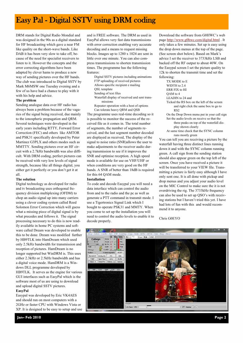
Download the software from G0HWC’s web
page http://www.g0hwc.com/digital.html . It
only takes a few minutes. Set up is easy using
the drop down menus at the top of the page.
(See screen shot below). Based on Mark’s
advice I set the receiver to 3733kHz LSB and
backed off the RF output to about 40W. On
the Easypal screen I set the picture quality to
12k to shorten the transmit time and set the
following:
TX MODE to E
WIDTH to 2.4
ERR FIX to HI
QAM to 4
LEADIN to 24 and
Ticked the RS box on the left of the screen
and right click the same box to go to
RS2
On the Drop Down menu put in your call sign
Set the audio levels on receive so that the
three peaks on top of the waterfall dis-
play shown clearly
At same time check that the SYNC column
runs mostly green
You can tell you are receiving a picture by the
waterfall having three distinct lines running
down it and with the SYNC column running
green. A call sign from the sending station
should also appear green on the top left of the
screen. Once you have received a picture it
will be transferred to your VIEW file. Trans-
mitting a picture is fairly easy although I have
only sent one. It is all done with pickup and
drop menus and you adjust your audio level
on the MIC Control to make sure the it is not
overdriving the rig. The 3733kHz frequency
can also be used to set up QSO’s with receiv-
ing stations but I haven’t tried this yet. I have
had lots of fun with this and would recom-
mend it to anyone.
Chris G0EYO
Easy Pal - Digital SSTV using DRM coding

Page 3 Jan– Feb 2010
HF Antenna Splitter for Receivers
Those of you that know me, will be aware of
my passion for old receivers. Having collected
so many I thought it was about time I switched
them on and used them occasionally. One of the
problems in having a number of sets is, what do
you do about a receive antenna? Essentially a
long wire will suffice for most applications
from 1.5-30MHz, but which receiver to connect
it to? Getting to the back of some of my big old
sets is a bit difficult so changing the antenna
from one set to another was best to be avoided.
The answer lay in an Antenna Splitter. This
comprises a simple, but low noise, RF amplifier
and a toroidal transformer with sufficient wind-
ings on it to feed the number of receivers you
want to have connected to your antenna. The
amplifier is there to provide gain to counter the
losses you suffer feeding the antenna
through the transformer. Two outputs
would have 3dB loss. Four outputs 6dB
loss. With three outputs I needed at
least 5dB of gain. I found a suitable
circuit on the internet.
I wanted to make this using as much
stuff as I could find from my junk box.
The case was something that I found
down the club and so I cleaned it up and
painted it black. There were enough
holes already drilled in it to mount a
SO239 socket for the antenna input and
3 x SO239 sockets for the outputs. A
DC input connector, switch and LED sorted
the power out. (I already had a wall-
wart which gave 12V out). I decided
to put an extra 1000uF of smoothing
in the 12v line after the switch as
wall warts are notoriously noisy.
The transformer was wound with
32SWG enamelled wire. I cut four
lengths, one for the input and three
for the outputs. Connecting one end
of the four wires together (this would
be the earth connection) I gradually
wound them around a 35mm toroid
that I had in the junk box. This was
stuck to bottom of the chassis with a
piece of ―Blutack‖.
The pre-amplifier board was made up on a
piece of vero-
board. I used a
BF115 NPN
transistor
which seemed
to have suitable
low-noise char-
acteristics and
comfortably
covered the
frequency
range. The pre-
amplifier cir-
cuit was a ver-
sion of a circuit
developed by
David Norton
and Allen Po-
dell in June
1974. The Nor-
ton design uses
transformer
coupling to
achieve
―noiseless
negative feed-
back‖ and is
reckoned to
have outstanding performance. The Norton
amplifier demands that you keep all com-
ponent leads as short as possible. I sketched
the layout out on a piece of paper before I
started working on the veroboard. The tran-
sistor collector has ferrite beads to aid sta-
bility and should squash any oscillations
that may develop. I decided to make a
9.5dB amplifier so N= 5 turns and M=3
turns on dual core ferrites. It was best to
start off by making these transformers and
carefully placing them on the board before
mounting the other components. You need
to clearly identify the lead ends as desig-
nated in the circuit Ma Mb Na Nb.
Once the board was complete I tested it by
injecting a low level signal at the input
from my signal generator (say 14.2MHz)
and also monitoring it on the scope in chan-
nel 1. I then monitored the output on the
scope’s channel 2 to see what gain I was
getting and whether I was getting any dis-
tortion. I did the same for other frequencies
across the band 1.5-30MHz.
When I was satisfied with the performance
of the pre-amplifier I mounted it in the case
and made a label for the front which also
covered up the original holes in the case. I
have yet to try it on air as I need to do some
work on the receiving antenna but it was an
interesting project with most parts coming
from the junk box.
Chris G0EYO
HF RECEIVER NO 1
HF RECEIVER NO 2
HF RECEIVER NO 2
ANTENNA INPUT
R2 51R
L1 RFC
22uH
R3 2k
R4 8K2
R1 100R
C2
0.01uF
C1
0.01uF
C4
0.01uF
C5
0.01uF
C3
0.01uF
FERRITE BEADS
TR1
TR1 2N5109 OR MRF581
OR ANY LOW NOISE RF
SIGNAL AMPLIFIER
I USED BF115
L3 PART
L3 PARTL2
1a
1b
L2
1b
1a
Ma
Mb
Na
Nb
TRANSFORMER WINDINGS
32AWG ENAMELLED
GAIN 6dB N=1 M=2
9.5dB N=5 M=3
12dB N=11 M=4
14dB N=19 M=5
L3
HF ANTENNA SPLITTER DRAWN BY G0EYO
+
1k2
C6
1000uF
25V
Power switch
+12V
0V
Nb
Na
Mb
Ma
The original prototype took
me about 6 hrs. to construct
from scratch. When I tried it
out on my 40m full wave
loop, to my amazement it
worked like a dream; bal-
ance was perfect and the
transfer of power was as
good as either of my current
ATU`s. Much easier to tune
and impossible to tune up
incorrectly. It will only
match the antenna at one
setting, unlike many other
designs where a 1.0:1 SWR
can be obtained at more than
one setting.
I felt it was an ideal first project for any
newly licensed Ham and indeed for anyone
searching for a great ATU at a reasonable
cost.
I can assure you this will equal, and in
many cases exceed the performance of any
commercial ATU, no matter how much you
pay for it; quite frankly I am amazed by it.
Over the years I have been searching for the
ultimate ATU, now I really believe I’ve
found it. On my 40m loop It gives me a
1.0:1 SWR on all bands 40m. through to
10m. On 80m. I switch my loop to a ran-
dom wire (approx. 7/16ths. of a wavelength
long) again 1.0:1 no problem. It also tunes
this length of wire right through to 10m.
I`ve also tried another random piece of wire
approx. 36ft. long; it tuned this 80 through
to 10m. without batting an eyelid. Just to be
certain it was OK on a dipole I put up a
temporary one fed with twin speaker wire,
approximately a ½ wave on 20m. again a
perfect 1.0:11 match easily obtained and
perfectly balanced.
I cannot guarantee that the unit will tune
anything with the values used for the coil
and capacitor. In some rare instances you
may need more capacity or more induc-
tance. This is because some antenna lengths
may present extreme impedances, if this is
the case adding or subtracting one or two
feet from the offending antenna will nor-
mally cure the problem. .
The matching system used is the ―L‖
match, this is a very low loss system trans-
ferring maximum power to the antenna.
Most commercial ATU`s use the ―T‖ match
Page 4 Jan– Feb 2010
G3PQP Multi-match ATU
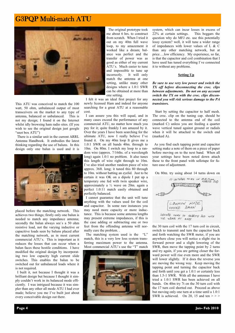
This ATU was conceived to match the 100
watt, 50 ohm, unbalanced output of most
transceivers on the market to any type of
antenna, balanced or unbalanced. This is
not my design; I found it on the Internet
whilst idly browsing ham radio sites. (If you
wish to see the original design just google
―snot box ATU‖)
There is a similar unit in the current ARRL
Antenna Handbook. It embodies the latest
thinking regarding the use of baluns. In this
design only one balun is used and it is
placed before the matching network. This
achieves two things; firstly only one balun is
needed to match any impedance antenna;
secondly the balun always see`s a 50 ohm
resistive load, not the varying inductive or
capacitive loads seen by baluns placed after
the matching network, as in most current
commercial ATU`s. This is important as it
reduces the losses that can occur when a
balun faces these hostile conditions. I have
modified the original design by incorporat-
ing two low capacity high current slide
switches. This enables the balun to be
switched out for unbalanced loads where it
is not required.
I built it, not because I thought it was a
brilliant design but because I thought it sim-
ply couldn’t work in its balanced mode effi-
ciently. I was intrigued because it was sim-
pler than any other all mode ATU I had ever
made; believe you me I’ve built just about
every conceivable design out there.
system, which can incur losses in excess of
22% at certain settings. This beggars the
question why do MFJ etc. use this potentially
lossy system? well, it will tune a wider range
of impedances with lower values of L & C
than any other matching network, but at
price….low efficiency. My experience, so far,
is that the capacitor and coil combination that I
have used has tuned everything I`ve connected
it to without any problems.
Setting Up
Be sure to use very low power and switch the
TX off before disconnecting the croc. clips
between adjustments. Do not on any account
switch the TX on with the croc. clips discon-
nected you will risk serious damage to the PA
transistors.
Start by setting the capacitor to half mesh.
The croc. clip on the tuning cap. should be
connected to the antenna end of the coil
(marked C) unless you are feeding a quarter
wave vertical tuned against ground or radials
when it will be attached to the switch end
(marked A).
As you find each tapping point and capacitor
setting make a note of them on a piece of paper
before moving on to the next band. When all
your settings have been noted down attach
these to the front panel with sellotape for fu-
ture ease of adjustment.
On 80m. try using about 14 turns down on
the 30 turn coil with the 17 turn coil in circuit,
switch to transmit and turn the capacitor back
and forth watching the SWR meter, if you are
anywhere close you will notice a slight rise in
forward power and a slight lowering of the
SWR, then move the tapping point by 2 turns
and try again, if you are getting closer the for-
ward power will rise even more and the SWR
will lower slightly. If it does the reverse you
are moving the wrong way. Keep moving the
tapping point and turning the capacitor back
and forth until you get a 1.0:1 or certainly less
than 1.5-1 SWR. With all the antennas I have
tried a 1.0:1 SWR has been achieved on all
bands. On 40m try 7t on the 30 turn coil with
the 17 turn coil shorted out. Proceed as above
but moving only one turn at a time until a 1.0:1
SWR is achieved. On 20, 15 and ten > > >
Page 5 Jan– Feb 2010
Xmas Party - everyone’s a winner
G3PQP Multi-match ATU continued
Club Diary
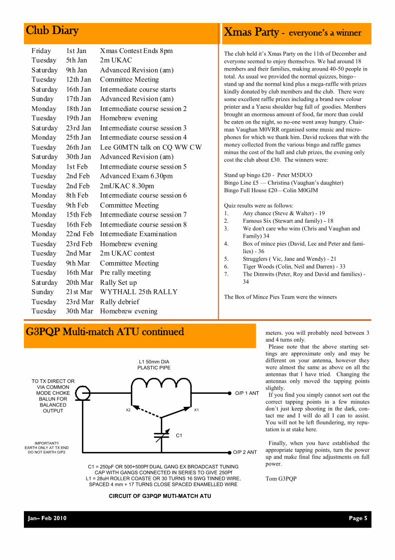
TO TX DIRECT OR
VIA COMMON
MODE CHOKE
BALUN FOR
BALANCED
OUTPUT
L1 50mm DIA
PLASTIC PIPE
O/P 1 ANT
O/P 2 ANT
C1
C1 = 250pF OR 500+500Pf DUAL GANG EX BROADCAST TUNING
CAP WITH GANGS CONNECTED IN SERIES TO GIVE 250Pf
L1 = 28uH ROLLER COASTE OR 30 TURNS 16 SWG TINNED WIRE,
SPACED 4 mm + 17 TURNS CLOSE SPACED ENAMELLED WIRE
IMPORTANT!!
EARTH ONLY AT TX END
DO NOT EARTH O/P2
CIRCUIT OF G3PQP MUTI-MATCH ATU
X1X2
meters. you will probably need between 3
and 4 turns only.
Please note that the above starting set-
tings are approximate only and may be
different on your antenna, however they
were almost the same as above on all the
antennas that I have tried. Changing the
antennas only moved the tapping points
slightly.
If you find you simply cannot sort out the
correct tapping points in a few minutes
don`t just keep shooting in the dark, con-
tact me and I will do all I can to assist.
You will not be left floundering, my repu-
tation is at stake here.
Finally, when you have established the
appropriate tapping points, turn the power
up and make final fine adjustments on full
power.
Tom G3PQP
The club held it’s Xmas Party on the 11th of December and
everyone seemed to enjoy themselves. We had around 18
members and their families, making around 40-50 people in
total. As usual we provided the normal quizzes, bingo–
stand up and the normal kind plus a mega-raffle with prizes
kindly donated by club members and the club. There were
some excellent raffle prizes including a brand new colour
printer and a Yaesu shoulder bag full of goodies. Members
brought an enormous amount of food, far more than could
be eaten on the night, so no-one went away hungry. Chair-
man Vaughan M0VRR organised some music and micro-
phones for which we thank him. David reckons that with the
money collected from the various bingo and raffle games
minus the cost of the hall and club prizes, the evening only
cost the club about £30. The winners were:
Stand up bingo £20 - Peter M5DUO
Bingo Line £5 — Christina (Vaughan’s daughter)
Bingo Full House £20—Colin M0GJM
Quiz results were as follows:
1. Any chance (Steve & Walter) - 19
2. Famous Six (Stewart and family) - 18
3. We don't care who wins (Chris and Vaughan and
Family) 34
4. Box of mince pies (David, Lee and Peter and fami-
lies) - 36
5. Strugglers ( Vic, Jane and Wendy) - 21
6. Tiger Woods (Colin, Neil and Darren) - 33
7. The Dimwits (Peter, Roy and David and families) -
34
The Box of Mince Pies Team were the winners
Friday 1st Jan Xmas Contest Ends 8pm
Tuesday 5th Jan 2m UKAC
Saturday 9th Jan Advanced Revision (am)
Tuesday 12th Jan Committee Meeting
Saturday 16th Jan Intermediate course starts
Sunday 17th Jan Advanced Revision (am)
Monday 18th Jan Intermediate course session 2
Tuesday 19th Jan Homebrew evening
Saturday 23rd Jan Intermediate course session 3
Monday 25th Jan Intermediate course session 4
Tuesday 26th Jan Lee G0MTN talk on CQ WW CW
Saturday 30th Jan Advanced Revision (am)
Monday 1st Feb Intermediate course session 5
Tuesday 2nd Feb Advanced Exam 6.30pm
Tuesday 2nd Feb 2mUKAC 8.30pm
Monday 8th Feb Intermediate course session 6
Tuesday 9th Feb Committee Meeting
Monday 15th Feb Intermediate course session 7
Tuesday 16th Feb Intermediate course session 8
Monday 22nd Feb Intermediate Examination
Tuesday 23rd Feb Homebrew evening
Tuesday 2nd Mar 2m UKAC contest
Tuesday 9th Mar Committee Meeting
Tuesday 16th Mar Pre rally meeting
Saturday 20th Mar Rally Set up
Sunday 21st Mar WYTHALL 25th RALLY
Tuesday 23rd Mar Rally debrief
Tuesday 30th Mar Homebrew evening
Page 6 Jan– Feb 2010
How to improve your G5 RV aerial (Without maths and in plain English)
Louis Varney’s original aerial was designed
to optimise his transmitting and receiving
capability on a limited budget from a modest
house and garden.
Sounds familiar? Lets look at what his own
antenna system comprised. His rear garden
was about 100ft long, he had a tree at the
end and his house with chimney at the other.
His favourite band was 20m CW (14 Mhz
Band) OK, Lee ? But, he wanted to work
other bands as well.
He wanted to have more gain than a classic
half wave dipole and not have significant
nulls off the ends, so a 1.5 wavelength on 20
metres, top was chosen for CW on 20metres.
This worked out as a 103 ft top section. It had
two major lobes and four minor lobes to give
almost 360 degree propagation. Now this was
fine for 20 metres operation, But what about
other bands ??
His solution was to feed the top section as a
doublet antenna with an ― Aerial System
Tuning Unit ― NOT an ordinary type of
impedance matching ATU !. Electrically
speaking, a doublet antenna is two inverted L
antennas mounted back to back such that the
parallel vertical feeder lines are balanced and
do not radiate. The aerial system tuning unit
loads and resonates each half of the antenna
equally and by switching the loading coils as
balanced pairs for each band and final
adjustment with separate or ganged capacitors
to achieve ― resonance ―
Yes, just like two base loaded verticals side
by side with the tops bent away from each
other so in fact, a fixed length doublet can be
resonant on any chosen frequency.
So what about the usual G5RV you say? It’s
not like that at all. It’s 102 ft long and has a
length of feeder section of 300 ohm, 450 ohm
or 600 ohm ladder line coupled to a length of
coax which goes straight to my ordinary
impedance matching ATU. The length of
―impedance matching line ― should be an
electrical half wavelength at 20 metres which
helps the top section tune easier on 20 metres
and other bands. However, when tuned on
other bands the coaxial feeder length can be
critical to obtaining a good or possible match
at the 50 Ohms impedance required for most
rigs. The feeder line and coax cable is then
said to be reactive. That is when there are
standing waves on the feeder line and
different values of SWR will be measured
dependent upon the length without changing
the length of the top section. It is well known
that this more usual version of the G5RV
also works well on 80m and other bands
Now with reference to a ― Smith Chart ― ( If,
you understand them, but it doesn’t matter if
you don’t ) The 40 metre band has the
highest SWR and can be difficult for some
ATU’s to achieve a 1:1 SWR match at 50
ohms impedance.
What do you do ? The easy way is to cut a
pair of dipole lengths for 40 metres ( 33ft
each ) and connect them to the same
feedpoint, then radiate them at 20 to 30
degrees away from the original top section. AND.................BINGO...............40 metres
will now be much easier to tune and 15
metres should bring in more stations as this
is now also a 1.5 wavelength dipole for 15
metres. If you’re fussy, you can now
carefully match each leg of your antenna for
the repective the bands by shortening or
extending to achieve a dip ( Minimum
SWR ) at the centre of each band.
You will now have slightly more gain as
ALL of the antenna legs receive, ALL of the
antenna legs transmit and either of the
dipoles will RESONATE at the frequency in
use ( Now 40 metres, 20 metres and 15
metres ). Therefore, NO traps to buy or
make, less weight in the air and cheap to
make, dead easy too. Any old electrical wire
will do, any colour, with or without
insulation. If you are happy with the
performance then you can tidy it up later
with flexiweave or similar.
Getting it up and keeping it up For most antennas and bands, ―HEIGHT IS
MIGHT ― so poles on chimneys, poles down
the garden as well as lovely high trees are a
necessity especially when skyhooks are
now in short supply. Single dipole
antennas are fairly straightforwards to erect
but can still blow down in gales when it all
gyrates like a gigantic skipping rope.
Firstly, to prevent the soldered tags
breaking off from the aerial wire at the
dipole centre, simply cut a couple of 3 inch
lengths of half inch garden hose and pass
the aerial wires through them at the dipole
centre. Thus the wires won’t snatch at an
angle to the soldered joints..........It really
works !!
“ My trees wave about in the wind
“............So do mine !! Each leg of my antenna is connected to an
insulator then to pre-stretched nylon line
which then passes over a pulley and then
vertically down to a rubber luggage bungee
with hooks. Sounds simple,it is,if you like
climbing trees. I attach the pulleys ( small
yacht or dinghy blocks ) with a suitable
screwed ― shackle‖ which couples to an old
car fan or generator belt which is then
doubled around a convenient tree branch.
So far so good. The Nylon rope is then
looped loosely around a lower branch and
secured with a ― Bowline ― knot. The loose line is then pulled through the
pulley until the desired aerial height and
tension is achieved. A simple loop knot is
then tied a foot or more below the pulley and
the hooked bungee is then connected
between the lower loop and the loop knot.
The spare line used to raise and lower the
antenna is then gathered up and looped and
secured onto the lower loop.
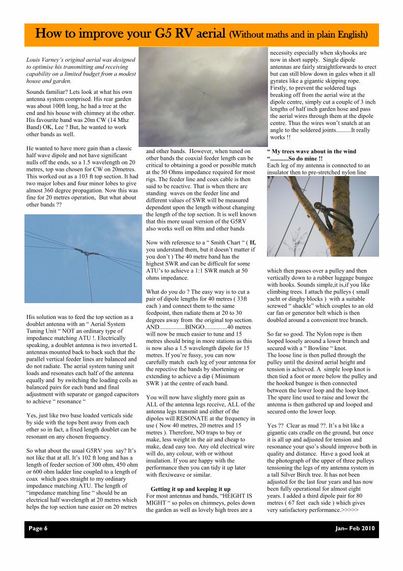
Yes ?? Clear as mud ??. It’s a bit like a
gigantic cats cradle on the ground, but once
it is all up and adjusted for tension and
resonance your qso’s should improve both in
quality and distance. Have a good look at
the photograph of the upper of three pulleys
tensioning the legs of my antenna system in
a tall Silver Birch tree. It has not been
adjusted for the last four years and has now
been fully operational for almost eight
years. I added a third dipole pair for 80
metres ( 67 feet each side ) which gives
very satisfactory performance.>>>>>

Page 7 Jan– Feb 2010
Another 100% success story
Six of our students took the Advanced ex-
amination in December and a couple of days
before Christmas they all heard that
they had passed. So well done, Dar-
ren, Mike, John, Neil, Stuart and
Walter. Walter and Stuart started
with their Foundation course in
October 2008 and John did his
Foundation course with us in April
2009. They all, together with Dar-
ren and Mike who came from Mal-
vern did their Intermediate with us
in May. Finally, Neil who passed
his intermediate with us a year ear-
lier started the 15 week Advanced
Course in September. This was a
pretty intensive course and we held
a couple of revision morning to-
wards the end of the course to build up their
confidence in the use of formulae and also
basic electronics. Wythall’s courses are de-
veloping as we do them and I am confident
Training Report
This the business end of my RG214 coax to a
1:1 Voltage balun rated at 2 Kw feeding
Belden 72 Ohm transmission line up to the
dipole centre. The vertical tube is plastic pipe
which allows the the transmission line to loop
well clear of the ground and prevents
snatching in high winds. As I live very close
to overhead three phase powerlines this type
of balun passes any static voltage build-up to
earth. ( The hollow pole on the brackets is a
stiff plastic tube )
73’s de Nigel ( G4 NRR )
After a week of snow
and ice, it was a relief
that the day of the Fox
Hunt on the day after
Boxing Day turned out
to be a glorious sunny
day with the previous
night’s rain having
washed most of the
snow away. Fourteen
of us turned up at the
Barley Mow in Stud-
ley, though not all at
the designated time of
9.45am for a 10am
kick off. It was good to
see some new club
members taking part, Jon 2E0JMM and
Darren M0JJM, Mike M0JVP and Andy
G1?. They were joined by Chris G0EYO
and Peter M5DUO, Vaughan M0VRR,
Sherryn M3SVR and Nick N6NJR and his
sister Christina, Chris G6KMQ and Paul,
and finally Steve 2E0SDD, Stacey and
Stuart 2E0NYC. This gave us six teams.
Chris G0EYO and Peter M5DUO
Chris G6KMQ and Paul
Vaughan M0VRR, Sherry M3SVR
and Nick M6NJR
Steve 2E0SDD and Stuart 2E0NYC
Darren M0JJM and Jon 2E0JMM
Mike M0JVP and Andy G1?
Chris KMQ went off to be the first fox and
he was eventually found by Vaughan.
Vaughan became the fox and was fairly
quickly found by Chris KMQ. As Chris
KMQ had already been a fox Chris EYO of-
fered him and Pete to be the fox as they were
completely lost and reckoned that as they
didn’t know where they were, then others
would find it hard to find them. Eventually
Jon 2E0JMM and Darren M0JJM found them
and so Jon and Darren went off to be the fox
and were found by Vaughan. Towards the end
of the fox hunt we started to be interfered with
by a station somewhere in the Astwood Bank
Headless Cross area. Whistling, DTMF tones,
playing music etc., however we had great fun
and it was decided that it would be a good
time to break for lunch so we made our way
back to the Barley Mow and it was there that
most of us had a good lunch and a few laughs
reminiscing our experiences of the morning.
Chris G0EYO
we can offer one of the best training pro-
grammes in the region.
Our next course will be an Intermediate one
starting on the 16th of January and we cur-
rently have 6 students signed up for that
course. If anyone knows of anybody look-
ing for a Foundation course let me know as
we will be planning a Foundation course for
April.
Chris G0EYO
Xmas Fox Hunt 2009
L:R; Walter M0GRO, Mike M0JVP,
Neil, John M0RJH, Stuart, and Darren
M0JJM just before their examination

Contest Group Report Happy New Year from me. The start of the
year is traditionally a time for forward plan-
ning, so why not consider what contests you
might be interested in over the next few
months. January sees the start of the 80m
Club Championships. There are three 90 min-
ute sessions per month, one on SSB, one on
CW, and one using RTTY and PSK. In the
first few months, propagation can be a little
challenging, but as we get towards the sum-
mer, the bands will be jam packed full of local
UK signals. The club has taken part in these
every year, and has normally ended up with a
placing in the top third of clubs. Also the
VHF / UHF UKAC activity contest season
restarts. 2009 was a good year for Wythall in
the 2m UKAC, so why not give this a try in
2010? Even a short spell of activity in a few
sessions throughout the year will bring some
good results.
Aside from the regular events, there are the
80m AFS contests in January. These are 4
hours long, and stations can use high power,
so it’s fun to try to keep up with the leaders.
February sees the final AFS contest with 432
MHz AFS. Maybe we’ll have more activity
from the club shack this year too – please let
me know about any ideas or suggestions.
As I write this, the Christmas Contest is still
in full swing, but the 1st Jan end is getting
ever closer. Don’t forget to send your Christ-
mas Contest logs in to me as soon as possible.
Any format will do – text file, spreadsheet, or
paper logs. I can then do a spot of cross
checking and help form the overall results. It
would be a shame if over half of the club
membership take part in this competition, but
I’m only able to present scores for a small
number in the results table. The full results
will be presented in the next Newsletter, and
the first official results and the presentation of
the Reg Brown Trophy and certificates will
happen as part of the February committee
meeting.
Lee G0MTN
G0MTN visits K3LR for CQ WW CW
As reported in the last newsletter, at the end of
November I flew to Pittsburgh to be part of
the K3LR team for the CQ WW CW contest.
7752 scoring QSOs were keyed in 48 hours by
the 12 man team. I was on 20 metres, and 4
times 6 element yagi’s to use for the run sta-
tion, and the multiplier hunting station had 2
times 6 element yagi’s. The top antenna is
situated at 230 feet, just next to the aircraft
warning beacon. The scale of the engineering
and dedication to this station is truly amazing.
Editor: Chris Pettitt G0EYO, 23 Dark Lane, Hollywood, Birmingham, B47 5BS. Phone: 07710 412 819, E-mail: [email protected]
Page 8 Jan– Feb 2010
The next issue of the Wythall Radio Club Newsletter will be published at the beginning of March 2010
I’ll be giving an illustrated talk to the club on
January 26th at 8.30. Please come along if
you’d like to see what goes in to building,
and then operating from a US ―super-
station.‖
RSGB VHF Contests:
Date (2010) Time
UTC Contest Name Sections Notes/Special Rules
Every 1st
Tuesday
2000-2230
(Local) 144MHz UKAC
AO AR QTH Locators , Activity
contest , Club Championship
Every 2nd
Tuesday
2000-2230
(Local) 432MHz UKAC
AO AR QTH Locators , Activity
contest , Club Championship
Every 3rd
Tuesday
2000-2230
(Local) UHF UKAC
AO AR QTH Locators , Activity
contest , Club Championship
Every 4th
Tuesday
2000-2230
(Local) 50MHz UKAC
AO AR QTH Locators , Activity
contest , Club Championship
Every 5th
Tuesday
2000-2230
(Local) 70MHz UKAC
AO AR QTH Locators , Activity
contest , Club Championship
7 Feb. 0900-1300 432MHz Affiliated
Societies Contest
O SF Affiliated Societies contest
28 Feb. 1000-1200 70MHz Cumulatives
#1
O SF Cumulative contest
6-7 Mar. 1400-1400 March 144 432MHz
SF SO O
6S 6O
RSGB HF Contests:
Date Time (UTC)
Contest Name. Dates - Mode - Frequency - Exchange
January 2000-2130.
80m Club Championships 5th - CW; 14th - SSB; 22nd - Data
Jan 11 1400-1800.
Affiliated Societies Team Contest
3510-3590kHz, RST+Serial (CW)
Jan 17 1400-1800.
Affiliated Societies Team Contest
3600-3750kHz, RS+Serial. (SSB)
February 2000-2130.
80m Club Championships 2nd – SSB; 11th – Data; 19th - CW.
Feb 14/15 2100-0100.
1st 1.8Mhz Contest 1810-1870kHz, RST+Serial+District.
March 2000-2130.
80m Club Championships 2nd – Data; 11th – CW; 19th - SSB.
Mar 14/15 1000-1000.
Commonwealth Contest 3.5-28MHz, RST+Serial.
Lee on front cover of
Radcom(on mic)