meemhehh lfflllfflllffl. - apps.dtic.mil · n pressure interactions in supersonic combustioni...
TRANSCRIPT

RD-R172 71 PRESSURE INTERACTIONS IN SUPERSONIC CONSUSTIOW(U) 1CENCE RPPLICRTIONS INTERNRTIONRL CORP CHAYSNOETH CA
COMBUST.. R B EDELMAN ET AL. 11 JUN 86UNCIFE jERTR*-0?
4 j69-4--0**** 2/2M
MEEMhEhhI lfflllfflllffl.

liling I"

AFOSR-TR.a f3 - 8 6
N PRESSURE INTERACTIONS IN SUPERSONIC COMBUSTIONI
'4,, FINAL REPORTIAl IF, C' T L- F I'RZSj
Thi3 t(!c, ',,c:t h'ia be!-i rev:
apprved*~rc~.~zuIAWA
Scienc Apication Internaiona Corporaio
All rY'h 'Z 11:rt IT ~ ro ~~~r1
%1Cr. I.
7b' s t Ahoq:ic. rov -iv *.,dJ u*Li.is
r)vI * c rao~i
Q.D OCT 0 8 NO,LAW
.. j

Science Applications International Corpoation "
SAIC 86/1739
JgFOSR-TR- f A- 0 8 7 6
p
PRESSURE INTERACTIONS IN SUPERSONIC COMBUSTION
A. FINAL REPORTAIR FORCE OFFICE 01 Z"CTUTTTFIC RSARCH (AFSC)
NT CE OF TRA?P317 TT AL TO DOTI CThis technic -I -eport his been reviewed and Isapprovedf.-- -", 1i"rele.4se IAW AFR 1!0-].2.,Distrit t- . :. .unlimited. ;Pr.u h1. *u.m'
Chief, Teohnical Information Division
* SUBMITTED BY:
SCIENCE APPLICATIONS INTERNATIONAL CORPORATION
COMBUSTION SCIENCE AND ADVANCED TECHNOLOGY DEPARTMENT
9760 Owensmouth Avenue
Chatsworth, California 91311 Approved forpublic rles..distribution ulmtd
Contract No. F49620-84-C-0064
PREPARED FOR:
AIR FORCE OFFICE OF SCIENTIFIC RESEARCH
BOLLING AIR FORCE BASE
Washington, D.C. 20332 D T ICAELECTE
OCT 0 8 5
June 11, 1986 D
iX%!S

REPORT DOCUMENTATION PAGEis REPORT SECURITY CLASSIFICATION 1b. RESTRICTIVE MARKINGS
Unclassified None>%2& SECURITY CLASSIFICATION AUTHORITY 3. DISTRIBUTION/AVAILABILITY OF REPORT
2b. OECLASSIFICATION/OOWNGRAOING SCHEDULE Distribution unlimited; approved forpublic release
4, PERFORMING ORGANIZATION REPORT NUMBERCS) 5. MONITORING ORGANIZATION REPORT NUMBER(S)• _ _ _ __AFOSR-TR- -00876
.6& NAME OF PERFORMING ORGANIZATION tI . OFFICE SYMBOL 7a. NAME OF MONITORING ORGANIZATION
Science Applications ationtwcble) Air Force Office of Scientific ResearchInternational__rrporation _________________________________
6c. ADDRESS lCIty. Slate eand ZIP Code) 7b. ADDRESS (City. Sta e and ZIP Code)
V.9760 Owensmouth Ave.,Chatsworth,CA 91311 Bolling AFB DC 20332-6448Vi
J. NAME OF FUNDING/SPONSORING Bb. OFFICE SYMBOL 9. PROCUREMENT INSTRUMENT IDENTIFICATION NUMBERORGANIZATION (If pplcabe)
Air Force Office of Sci.Res. AFOSR/NA F49620-84-C-0064*I .1 ADDRESS (City. S ae and ZIP Code) 10. SOURCE OF FUNDING NOS.
PROGRAM PROJECT TASK WORK UNITBolling AFB DC 20332-6448BOIin,. D 03264 ELEMENT NO. NO. NO. NO.
11. TITLE gOnclude Security Cia",icaion 61102F 2308 A2Pressure Interactions in Superson c omb.(Uncl__
12. PERSONAL AUTHOR(S)
R.B.Edelman and W.N.Bragg13a. TYPE OF REPORT 13b, TIME COVERED 114. DATE OF REPORT (Yr.. Mo.. Day) 15. PAGE COUNT
Final FROM 1 JUN 84To28 Feb8 1986, June 11 5516. SUPPLEMENTARY NOTATION
17. COSATI CODES 118. SUBJECT TERMS (Continue on rverse if n ecaoary and identify by btoch number)
FIELD GROUP SUB. GR. Supersonic Combustion .Sudden Expansion kf)mpf eCmbustors.,'Pressure Interactions. ModU4ar Model Com uter CodeTurbuhlnr Mndpling; . '.. - L3 # r.
19. .BSTRACT (Continue on reverse ifnecsmary and identify by block number)
A detailed assessment of supersonic combustionlias been carried out to identify specificresearch requirements in modeling turbulent reacting supersonic flows. The direct effects ofpressure gradients and pressure fluctuations on turbulence were found to be potentiallyresponsible for certain of the trends in turbulent transport and mixing rates that areobserved in supersonic flows. An approach to the modeling of these phenomena is delineated.A modular model computer code for the analysis of sudden expansion (dump) combustors wasprepared and delivered to the Air Force Aero Propulsion Laboratories (AFWAL/PORT). 'Thismodular model is designed to be used parametrically in evaluating effects such as chemicalkinetics limitation on flame stabilization and combustion efficiency in integral rocketramjet and ducted rocket combustors.
20. DISTRIBUTION/AVAILABILITY OF ABSTRACT 21. ABSTRACT SECURITY CLASSIFICATION
UNCLASSIFIEO/UNLIMITED 12 SAME AS RPT. C3 OTIC USERS 0 Unclassified
22a. NAME OF RESPONSIBLE INDIVIDUAL 22b, TELEPHONE NUMBER 22c. OFFICE SYMBOL
JulianM. Tisko(Include Aro Code)Julian M. Tishkoff (202) 767-4935 AFOSR/NA
DO FORM 1473, 83 APR EDITION OF 1 JAN 73 IS OBSOLETE. n i i fipd
SECURITY CLASSIFICATION OF THIS PAGC.
-•" " " " '. " ,.2. / - - 'i" -,- :- : ,-.,. ' ... .....-... o ",", . . .--- -,.. . - . .., -, -'

' 'TABLE OF CONTENTS
SECTION PAGE
1.0 RESEARCH OBJECTIVES AND SUNARY
2.0 INTRODUCTION 2
3.0 RESEARCH STATUS 3
.
4.0 PROFESSIONAL PERSONNEL 47
*% ,..
.N, 5.0 INTERACTIONS 48
% ,".*
*1
Accesion For
NTIS CRA&IDTIC TABUnannouiced U
'. "". Justificautio
By_~~ ~ ~~~ y .......................... ......
Dist ib.:tio:, IAvilabldity Codes
D i -. a:: i. a; or
4........
. .. • **** \*VV@ ***-*~ * ~ ... '.

LIST OF FIGURES
FIGURE # PAGE
I MACH NUMBER - VARIATION OF 0 WITH MACH NUMBER 5
2 SCHEMATIC OF EDDY MACH WAVE GENERATION MECHANISM. 8
3 EFFECT OF MACH NUMBER ON PREDICTED SPREAD RATE OF A2-D SHEAR LAYER, BASED ON OH's CORRELATION. 9
4 SCHEMATIC OF FLOWFIELD. 19
5 SCHEMATIC OF FLOWFIELD WITH LATERAL PRESSURE GRADIENT. 23
6 NUMERICAL NET FOR CHARACTERISTICS STEP. 26'0 . i-7.31
. 7 NUMERICAL GRID FOR MIXING STEP.
8 WALL INTERACTION.
9a WALL AND CENTERLINE PRESSURE DISTRIBUTION. 37
" 9b AXIAL DECAY OF HYDROGEN MASS FRACTION. 38
9c PRESSURE PROFILE AT x/R = 40.6 39
9d VELOCITY PROFILE AT x/R_= 40.6 39
, 9e TEMPERATURE PROFILE AT x/R= 40.6 40
9f HYDROGEN MASS FRACTION PROFILE AT x/Rj= 40.6 40
lOa WALL AND CENTERLINE PRESSURE DISTRIBUTION. 42
lOb AXIAL DECAY OF HYDROGEN MASS FRACTION. 43
lOc PRESSURE PROFILE AT x/Rj= 38.4 44
lOd VELOCITY PROFILE AT x/Rj= 38.4 44
lOe TEMPERATURE PROFILE AT x/Rj= 38.4 45
* S lOf HYDROGEN MASS FRACTION PROFILE AT x/R. 38.4 453
" TABLE
I INITIAL CONDITIONS FOR SAMPLE CASE 36

, : ; -- - U .- '
- - ' . w' rw'--J-~' w ° -v U -U -u -J . . -; ' -* J'o-I'a
LIST OF SYMBOLS
SYMBOL DESCRIPTION
a SPEED OF SOUND
C. CONSTANT
C p CONSTANT PRESSURE SPECIFIC HEAT
D. DIFFUSION COEFFICIENT
h STATIC ENTHALPY
H TOTAL ENTHALPY
-ij DIFFUSIONAL FLUX OF THE ith SPECIE
k,e TURBULENT KINETIC ENERGY
% ., I COORDINATE ALONG A CHARACTERISTIC
Le LEWIS NUMBER
, M MACH NUMBER
n COORDINATE NORMAL TO THE STREAMLINE
P PRESSURE
Pr PRANDTL NUMBER
q MAGNITUDE OF THE VELOCITY VECTOR
r RADIAL COORDINATE
R UNIVERSAL GAS CONSTANT
s COORDINATE ALONG THE STREAMLINE
T TEMPERATURE
• "u AXIAL VELOCITY
' V VELOCITY VECTOR
O WPRODUCTION RATE OF THE i SPECIES
- DUE TO CHEMICAL REACTIONS
ii

LIST OF SYMBOLS
SYMBOL DESCRIPTION
X STREAMWISE COORDINATE
y LATERAL COORDINATE
ai MASS FRACTION OF THE ith SPECIE
6i~o KRONECKER'S DELTA
*1j
E DISSIPATION RATE OR ANGLE
7) SPECIFIC HEAT RATIO
•P DENSITY
a SPREAD RATE PARAMETER
0 STREAMLINE DIRECTION RELATIVE TO THE
HORIZONTAL DIRECTION
j T VISCOUS STRESS TENSOR
p ABSOLUTE VISCOSITY-4
v STOICHIOMETRIC-COEFFICIENT
-. i
ivI
'-" p ".. " o " "-" " .. ".." - . .. ¢" •-. . .•.•.- .o .. "

SYMBOL LIST OF SUBSCRIPTS
i COORDINATE DIRECTION OR ith SPECIE
n DERIVATIVE WITH RESPECT TO n
0 FREE STREAM
p PRODUCTION REGION
s DERIVATIVE WITH RESPECT TO s
T TRANSFER REGION
LIST OF SUPERSCRIPTS
FARRE AVERAGED
TIME AVERAGE
S.

4 1.0 RESEARCH OBJECTIVES AND SUMMARY74
The work described in this report represents the results of research conducted on
S turbulent reacting flows in air-breathing propulsion systems. The effort involves
an assessment of research on supersonic combustion and the preparation of a modularmodel for delivery to the Air Force at Wright-Patterson Air Force Base. The
specific objectives of this research are summarized as follows:
a) SUPERSONIC COMBUSTION
Objective: Under this task area an assessment of supersonic combustion
research was to be carried out. The emphasis of this effort involves the
identification of fundamental phenomena that require research in order to
improve our understanding of fuel injection, mixing, flame stabilization
and flame propagation in supersonic combustion ramjet engines.
h Research Results: The results of the research conducted on this task include
the identification of pressure-turbulence interactions as a potential expla-
nation for trends in turbulent transport and mixing rates observed in super-
sonic flows. An approach to the modeling of these interactions including
direct coupling of the turbulence levels to pressure gradient and pressure
fluctuations is outlined in this report.
b) MODULAR MODEL
Objective: Under this task a model applicable to the analysis of two and
three dimensional combustion processes is to be prepared for the Air Force
(AFWAL/PORT) at Wright-Patterson Air Force Base. A computer code and"2 associated documentation is to be delivered to the Air Force.
Research Result: A basic modular model computer code was prepared and
.-. delivered, together with documentation, to the Air Force at Wright-Patterson
* Air Force Base. This modular model is designed for parametric studies of
the efforts of operating conditions and geometric factors on flame stabili-
zation and combustion efficiency. It is specifically relevant to thedetermination of chemical kinetic limitations on the combustion processes
in flow regions typically found in sudden expansion burner configurations such
as integral rocket ramjet and ducted rocket combustion chambers. This work
.' ' 2' .' -j ..'2 ,'j2 ..p ' . , -.-.. - .a - . .-_a,..I .-.- .. ...- .-...-.-- -.- - -4

is separately documented in a report entitled "A Simple Reactor
Flow Computer Code for the Analysis of Kinetic Efforts in Sudden
Expansion Dump Combustors", Report No. SAIC
2.0 INTRODUCTION
The advent of large scale space operations and interest in wide area defense
measures have revived interest in hypersonic propulsion systems using airbreathing,
supersonic combustion ramjet engines.
Supersonic combustion has been studied for a number of years, with much of the prior
emphasis having been on the demonstration that a supersonic fuel-air mixture could
be ignited and burned under some conditions. There has been far less emphasis on
understanding some of the more fundamental physical problems that accompany
supersonic combustion processes. Chemical kinetics and mixing have been observed
to be limiting mechanisms in high speed flows and have been responsible for flame
stabilization and poor combustion problems even when hydrogen is the fuel. These
problems become more critical when storable fuels such as liquid hydrocarbons and
slurries are used because of the additional times required for spray evolution,
mixing and reaction of the less reactive gaseous and particulate components of
S these fuels. Thus, the problem is extremely complex because of the involvement
of a number of interacting mechanisms. However, common to the supersonic combustion
process and independent of the fuel is the pressure field that is developed due to
mixing, as well as geometry, and the interaction of the instantaneous pressure field
with the turbulence in the flow. Chief among the phenomena that are not well under-
stood in supersonic flow is the unexplained rate of mixing which may be due. at
least in part, directly to pressure gradient and pressure fluctuation effects. It
has been evident for some years that supersonic shear layer mixing rates are
diffe-ent from those encountered in shear layers at lower speeds, and indeed,
* different from the mixing rate observed in a low-speed, two-fluid mixii.j layer in
which the density ratio is the same as that observed across a supersonic shear
layer. Since shear layers and the attendant mixing phenomena are encountered in a
variety of forms throughout the flowfield found within a supersonic-combustion
ramjet (scramjet) combustion chamber, this unexplained mixing rate phenomenon is
of critical importance in understanding the ignition and combustion process in
supersonic flows.
4.' 2
j- . , - ' . - ., .1 .: • " " . : _" - . . .. . . . . - . . - 1. ;

Because the physical cause of the difference in mixing ratr, between a subsonic
variable-density (two-fluid) mixing layer and a supersonic mixing layer having
the same overall density ratio is not well understood, attempts to describe this
phenomenon have rested primarily on the development of empirical factors which
are intended to characterize the modification of the turbulent kinetic energy
distribution in supersonic flows compared to that which exists in an "equivalent"
subsonic flow. But since these factors are not founded on basic grounds, it is
not surprising that the application of them fails to predict observations which
have been made in supersonic flows of current interest. For the same reason,
little confidence in the applicability of these semi-empirical factors over a
broad range of conditions can be expressed. Thus what is required is the
development of more fundamental physical descriptions of the phenomena that affect
the mixing rate in supersonic reacting flows. Such a development will reduce the
high level of uncertainty that now attends estimates of mixing and combustion
rates in a scramjet engine.
3.0 RESEARCH STATUS
There is considerable evidence that a major reason for the lack of understanding
in supersonic mixing is a lack of knowledge regarding the effects of both meanand fluctuating pressure gradients on the mixing rate in a compressible flow.These effects are apparent in supersonic flames and indeed in subsonic flows,since for all but incompressible flow the contribution to the overall turbulent
kinetic energy level of the pressure-related terms can be of the same order ofmagnitude as all other contributions. Overall, it has been found that the
pressure fluctuation and mean pressure gradient effects can manifest themselvesas either a source or a sink of turbulent kinetic energy. Thus their effects
on the overall mixing rate can be either positive or negative, pointing to a
potential for exercising some control of the overall mixing rate in a supersonicflow through control of pressure fluctuations and mean pressure gradients.
In the original development of the turbulent kinetic energy approach to the, analysis of turbulent mixing phenomena, attention was restricted to low speed,
incompressible and non-reacting flows. In this circumstance the effect of mean
pressure gradients with respect to turbulence production is, in terms of the
turbulent kinetic energy, identically zero. In an incompressible flow, the effect
3:"
'U!
| !!

of a mean pressure gradient is to redistribute the fluctuating energy among the
different components of the turbulence intensity, without affecting the overall
energy balance. A fluctuating pressure-velocity correlation remains to be dealt
with, but since this has the effect of an additional diffusion term, which is,
in many cases of incompressible flow, small compared to the other contributions
to the turbulent diffusion of turbulent kinetic energy, this correlation has
often been neglected. Despite these rather fundamental limitations with respectto the application of the turbulent kinetic energy equation to more complex
compressible and reacting flows, analyses of these more complex phenomena havebeen made, often with unexplained good success. However, in some fundamental
.-. and technologically relevant circumstances the analysis of flow phenomena using
the incompressible turbulent kinetic energy approach has not been s,.ccessful.
The supersonic planar shear layer provides a case in point.
K: A considerable amount of data, collected and analysed for use in the 1972
NASA-Langley conference on free turbulent shear flows, involved the planar free* shear configuration. These data, reviewed by Birch and Eggers (Ref.l), involved
determinations of the spread rate parameter, U, in low speed, single-gas, com-
pressible, single-gas, and low-speed, two-gas flows. This spread rate parameter3 I is a measure of the width of the shear layer, and is easily obtained from experi-
mental velocity profiles, or from simple visual observations. Although U is a
parameter that arises from the analytical solution for a fully self-similar two-
dimensional flow, a specific definition can be expressed by the equation
0 CI * (X2 - Xl) / (Y2 - YI) (I)
where Y2 and Yl are the shear layer widths at X2 and Xl, respectively. The
constant Cl depends on the width definition. If the shear layer width, forexample, is defined as that between (U - Ul)/(U2 - Ul) = 0.10 and (U - Ul)/
(U2 - Ul) = 0.90, where Ul and U2 are the velocities on the different sides of
the shear layer, then Cl = 1.855 (Ref.2). Note that as U increases, the rate of
growth of the shear layer decreases.
4..................

IOLLUiEN (19261 _______________________
0 LIE PUL&NN onn I £UIt R 11947150 '0 GOOO[RUU WOOD cnd liRLVOORT 119501
'Q 1bRSHADEA 9.d PAl (3950)* CR&NE 119571o JOHANNESEN 19591A MWAYDEW end ,[ED 119631
*RHUIDY ed .4?.'LN t?966140- oSirl .. d ScLIc,,e (1966)
r CGLRS 11966) --A HILL neP4GL1 F1969) R 1 ,0 EWLRP VVGPJAP.SKI v!IIVELL( '7)~NWLR
*30- DATA
20-4 A A A AA
10 7Z
0o 2 3 4 5 6 7 8
MACH NUMBER
Figure 1. Variation of or with mach number.
I*I5
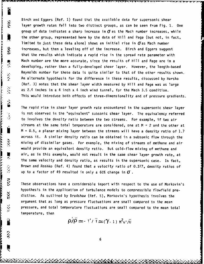
Birch and Eggers (Ref. 1) found that the available data for supersonic shear
layer growth rates fell into two distinct groups, as can be seen from Fig. 1. One
group of data indicates a sharp increase in UFas the Mach number increases, while
I the other group, represented here by the data of Hill and Page (but not, in fact,
limited to just these data alone) shows an initial rise in Uras Mach number
increases, but then a leveling off of the increase. Birch and Eggers suggest
that the results which indicate a rapid rise in the spread rate parameter with
Mach number are the more accurate, since the results of Hill and Page are in a
developing, rather than a fully-developed shear layer. However, the length-based
Reynolds number for these data is quite similar to that of the other results shown.An alternate hypothesis for the difference in these results, discussed by Harsha
(Ref. 3) notes that the shear layer width measured by Hill and Page was as large
* as 2.4 inches in a 4 inch x 4 inch wind tunnel, for the Mach 3.5 condition.
This would introduce both effects of three-dimensionality and of pressure gradients.
The rapid rise in shear layer growth rate encountered in the supersonic shear layer
S is not observed in the "equivalent" subsonic shear layer. The equivalency referredto involves the density ratio between the two streams. For example, if two air
streams at the same total temperature are considered, one at M = 2 and the other at
M = 0.5, a planar mixing layer between the streams will have a density ratio of 1.7
across it. A similar density ratio can be obtained in a subsonic flow through the
mixing of dissimilar gases. For example, the mixing of streams of methane and air
would provide an equivalent density ratio. But cold-flow mixing of methane and
air, as in this example, would not result in the same shear layer growth rate, at
- the same velocity and density ratio, as results in the supersonic case. In fact,
Brown and Roshko (Ref. 4) found that a velocity ratio of 0.377, density ratios of
up to a factor of 49 resulted in only a 60% change in (Y.
These observations have a considerable import with respect to the use of Morkovin's
hypothesis in the application of turbulence models to compressible flowfield pre-
diction. As outlined by Bradshaw (Ref. 5), Morkovin's hypothesis involves theargument that as long as pressure fluctuations are small compared to the mean
* pressure, and total temperature fluctuations are small compared to the mean total
temperature, then
P/P - T'/ T=(7- 1 M2u'/U
6

and this quantity will be small as long as u / U is small and ('Y- 1) M2
is not large compared to unity. If the fluctuation in density is sufficiently
S small then it can be neglected from the standpoint of turbulent transport.
Under these conditions a description of the turbulent transport process based
on incompressible flow is adequate. This hypothesis has been successfully used
' in the study of the development of compressible turbulent boundary layers.
Clearly it fails for turbulent shear layers, and because of the difference
* between supersonic shear layers and the "equivalent" variable-density flow, this
failure is a result of flow compressibility alone.
The observation of compressibility effects in supersonic shear layer development
led to the investigation of several "compressibility correction" techniques
intended to modify the turbulent kinetic energy distribution in supersonic flow
compared to that which exists in subsonic flows. One such approach is that
*described by Oh (Ref. 6). Oh's approach focused on the pressure-velocity cor-
relation term normally included in the overall diffusion of turbulent kinetic
energy, and specifically on a correlation between the fluctuating pressure andepvelocity dilatation. The development of the model involves invoking the exist-
j ence of eddy Mach waves which, following Phillips (Ref. 7) are supposed to be
generated whenever the difference in velocity between the high-speed side of
a shear layer and the covection velocity of an eddy exceeds the speed of sound
* ' in the high-speed fluid. This model is sketched in Fig. 2, and requires that
lateral transport of eddies take place rapidly enough that they retain much of
• their longitudinal velocity as they traverse the shear layer. Based on this
model, and using the continuity equation to write the pressure-dilatation cor-
relation in terms of mean flow quantities, Oh arrives at the expression given
by Eq. 2:a~'u, cV -2 ( a (t 1-U 2J~ OI P\
'M. - - _ c q 1 + sign __ 12)M_- Jaxi A axi ey BM y
pau i (2)M< I 0 =0
V. ax.
7
A A_.
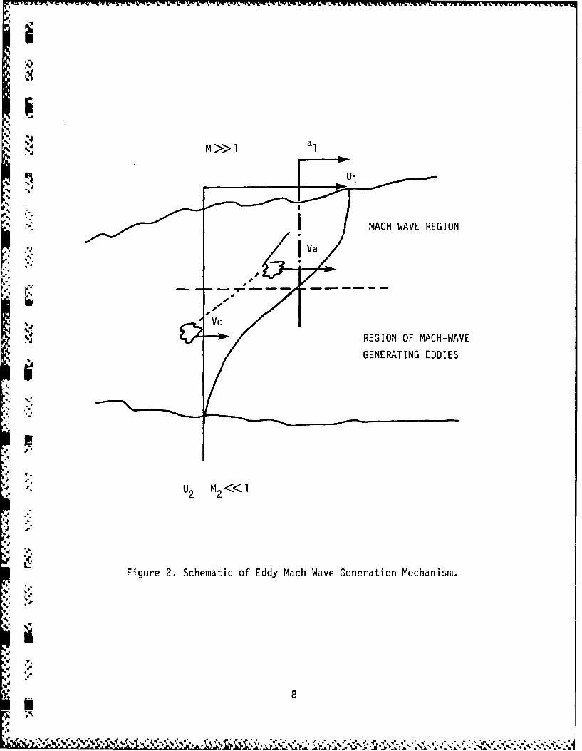
%M 1 a.
*qml
MACH WAVE REGION
REGION OF MACH-WAVE
4 f
Fiur 2.Shmtco dyMc Wv.eeainMcaim
*. q*8

.~I~UW~U wV ~w~wW EUWW wv J~~ Y U KW V~~ UM - V YP TJ v x jArV - 1% PwP~r~vPw VT U1W S- - .lu C - ' --
ADIABATIC FLOW0 LI[PMANN-LAUrER ,6 IKAWA0 MAYD[W-R[[D I MORRISEIT[ (IaRC UNPUBLISHD}'0 SIRI[IX-SOLI4AC -PREDICIION
0.0
.40
00.06
.2 0.09.
0.1..
0 l 2 3 4
e
Figure 3. Effect of Mach Number on Predicted
Spread Rate of a 2-D Shear Layer,
SBased on OH's Correlation.
xa
4'
' S:
9
.101

j&I " . J' p-K T A717777.1--
This semi-empirical approach provides the desired result for the spread rate of a
supersonic shear layer, as shown by the results presented in Fig. 3; the restriction
applied to the use of the correction for M(1 enables the subsonic variable-density
results to be recovered as well. However, no direction is provided by this approach
with respect to the treatment of the supersonic, two-fluid shear layer, which is a
fundamental flow element in a scramjet flowfield.
Dussage, et al. (Ref. 8) consider in some detail the properties and role of the
production of turbulent kinetic energy in a non-reacting supersonic flow. In their
analysis, the turbulent kinetic energy production term is separated into three
parts, one representing production due to pure strain, without density change,
another to pure dilatation effects, and a third which expresses the explicit effects
*i of mean pressure-gradients. These three components are given by Eqs (3)-(5) below,
using mass-averaged (Favre-averaged) variables*:
S Pure Strain
•-": - (pu"u" - PUkUk ) i + - 6i (3)-PIV- i j 3 ....k ij) xi ax 3 xk i
U
Z * Favre-averaging has been considered to provide a more natural set of dependentvariables in a compressible flow. They can be defined by the relation
t pg(t) dt- 0 Joto
whereas the conventional (or Reynolds - average) variable can be defined as
- 9t g(t) dt- t 0
where g is any vector quantity characterizing the flow.
i l
4
10
U

S Pure Dilatation
P 1 I u , DT
V = 3 puk k u Dt (4)
Pressure Effects
Pp = u + (p'u / ) P i Pp (5)i -ji
Note that the fluctuating velocity-pressure gradient correlation term in Eq. 5 is.. neglected in the rest of the analysis described by Dussauge, et al. Using an
order-of-magnitude analysis technique, Dussauge, et al. consider the influence
of the different production terms for a supersonic compression and a supersonic
expansion. The results indicate that the mean pressure gradient production
4. mechanism enters in the expanding flow (a shear layer downstream of a backstep),
where the dilatation effect is also of the same order of magnitude. In the case
..- of the compression, the isovolumetric production term dominates the overall-. production of turbulent kinetic energy, and indeed essentially reduces to the
"incompressible" form. Dussauge, et al. also consider eddy lifetimes in relation
to average flow times, and find that for the supersonic expansion, the eddy life-
time is long compared to the flow time through the expansion process. This, they
argue, indicates that in this case the changes in turbulence pattern that are
observed must come from the production of turbulent kinetic energy and is not as
* a result of alterations in the turbulent kinetic energy dissipation rate, which
would take longer to manifest themselves. The relationship is reversed in the
.~; compression case examined. From the standpoint of its relevance to a supersonic-" v combustion ramjet flowfield, this analysis indicates that different effects of
mean pressure gradient should be expected to be manifest in different parts of the
combustor flow.
Substantial effects of pressure gradients and pressure fluctuations have also beenpredicted to occur in low speed flames. For example, Libby and Bray (Ref. 9) show
that in a low-speed flame the action of the mean pressure gradient or densityb; inhomogeneities produces countergradient diffusion. The Rankine-Hugoniot relations
Sshow that the fluid experiences a small decrease in pressure upon traversing a
11p4 4
. ° ' " - - ., , , o -, - .* ', -, ",,. . • -. - '- , , , , ,-... , , . . - - , . . . . ,

flame zone. Burned gas pockets, being of lower density than unburned gas pockets,
will respond more readily to this decrease, and will exhibit a tendency to be
W driven farther downstream than the unburned gas. This effect on turbulent trans-
- port can be dominant (and is in a countergradient direction) if the heat release
is large compared to the initial thermal enthalpy, even though the effect of the
N pressure gradient on the average fix of momentum is entirely negligible.
F While Libby and Bray focus attention on the effect of mean pressure gradient and
neglect all effects of pressure fluctuations, Strahle and Chandra (Ref. 10)
neglect all effects of mean pressure gradient and focus attention on the effects
-. of pressure fluctuations, again for a low-speed flame. This focus demands the
development of modeling of the pressure-velocity correlation term appearing in
S the turbulent kinetic energy balance equation. In Favre-averaged variables,
Strahle and Chandra write the turbulent kinetic energy equation in the form:
. -q u."u. _ u " - j (6)PU_ - .-.. (Pu'!'q") -(Dx> xj Mxi (xi
and consider in detail the modeling of the last term on the right-hand side of
b Eq. (6). In equation (6) all of the variables are in a non-dimensional form
which is itself based on the use of high activation energy asymptotics to define
the structure of the premixed flame being considered. The term 0 represents the
* . dissipation of turbulent kinetic energy and is neglected in the further develop-
ment of the modeling in Ref. 10. Strahle and Chandra proceed by dividing the
• - velocity field into vortical and dilatational components, since, loosely, vortical
fluctuations can be identified with turbulence generation and dilatational fluctu-
ations with acoustic motions. By carrying out a detailed order-of-magnitude
analysis, they find that at high heat release rates the pressure fluctuations are
primarily diktational and hence do not strongly affect the turbulence energy
balance. At lower rates of heat release, the primary mode of fluctuation involves
the vortical components, and it is under these circumstances that a model for the
pressure-velocity fluctuation term in Eq (6) is required. For a planar, one-dimens-
ional premixed flame, and under the somewhat disturbing but nevertheless necessary
S" assumption that Favre- and Reynolds-averaged variables can be equated, there results
the expression:
u'. Vp' = d d2W (7)
M 2 dx dx2
0
12

where c is a constant of order unity and W represents the dilatational component
of the total velocity vector. Because Eq (7) involves the second derivative of
the dilatational component it is clear that dilatation is required for the
P. correlation to exist. Heat release is necessary.
i ' By using Eq (7) in a suitably modified form of the Bray-Libby theory (Ref. 9)
Strahle and Chandra show that, depending on the magnitude chosen for ae, sub-
* stantial effects on the turbulent kinetic energy balance can be predicted to
arise from the pressure fluctuations in a model reacting flow. In general, Eq. 7
represents a source of turbulent kinetic energy and acts to increase the turbulent
*. flame speed. Taken together, what both the analysis of mean pressure gradient
effects of Ref. 9 and of pressure gradient fluctuations in Ref. 10 show is that
neglecting either of these terms in a general reacting flow problem can be an
erroneous assumption. However, both of these analyses are limited to a simple
one-dimensional premixed, fast chemistry, flame approximation, and a great deal
of work remains to be done to generalize these results to conditions of interest
in the analysis of supersonic reacting flow.
An important factor in a theoretical approach is the role played by the turbulent
g length scale. Representing a mean eddy size, this length scale enters the
definition of the turbulent kinetic energy dissipation rate, and has been utilized
as well iP the definition of modeling for the fluctuating pressure-strain cor-relation terms (e.g., Rotta, Ref. 13). However, in all turbulent shear flows, a
p. spectrum of eddy sizes and therefore length scales exists, and thus the use of a
'* single length scale is equivalent to an assumption that all length scales are
* proportional, so that any one can be used to characterize the flow - an "equilibrium"
' assumption. Our hypothesis is that in the presence of strong pressure gradients
and compressibility effects this "equilibrium" no longer exists, so that different
length scales need to be defined for turbulence dissipation and for the pressure-
strain interaction, for example.
One piece of evidence for this hypothesis is the work reported by Hanjalic', et al.
(Ref. 14) involving the passage of e grid-generated decaying turbulent flow through
a contraction section. During this p,-ocess, the kinetic energy is observed to
S increase and then decay again, but at a slower rate than before. Two-equation
13

model predictions either underpredict the secondary energy peak and the subsequent
rate of decay, or overpredict both, depending on the constants selected. A model
incorporating two scales does successfully predict this flowfield, and the results
show that as the flow proceeds through the contraction section (and thus through
a mean pressure gradient), the initially equilibrium relationship between the two
scales of motion is altered.
An investigation was carried out of the multiple-dissipation-length scale approach
(Fabris, Harsha, and Edelman) Ref. 15 and it found that even in relatively simple
flows it provides a greater generality than the basic two-equation model: round
jet predictions can be made with the same coefficients as for other simple flows,
for example. However, this work did not involve consideration of the pressure-
strain term, or of strong pressure gradients, or of compressible flow, all of
which are of potential importance in high speed flows.
Viewed from the perspective of a multiple length scale model, the existence of
coherent structures represents the behavior of the flow at the largest scales of
interest. Energy is transferred from these scales to the smaller scales ofa motion, and it is this transfer process that provides the connection between the
observed coherent structure and classical turbulent flow models. Previous work
(Hanjalic', et al. Ref. 14 , Fabris, et al, Ref. 15) has limited the number of
scales to be considered, the transfer mechanism which we believe is Reynolds
number dependent and the equation formulation. Thus, in the previous work the
. Reynolds averaged variables have been used, with two scales and a direct transfer
of energy independent of local flow Reynolds number. For the flows to be considered
in this work, the approach is to systematically increase the number of scales
considered, with the largest scale described as a periodic (or quasi-periodic)
fluctuation, and a local Reynolds number-related energy transfer rate. At the
other end of the spectrum, a small-scale energy dissipation rate can be defined
to represent mixing on a scale consistent with that which applies to chemical
reactions.
In contrast, both the algebraic Reynolds stress model (ASM) and the k-E approaches
are single-point models which adopt a single time scale proportional to the turb-
b ulence energy turnover time, k/E . However, it is overly simplistic, at least
conceptually, to assume that a single time scale can successfully characterize the
rates of progress of different turbulent interactions.
"- 14

The key to the new multiple-scale approach is the recognition that while the
dissipation equation and the kinetic energy equation both contain production
and dissipation terms, these processes occur in different spectral rLgions of
the flow. That is, turbulence energy production occurs in the larger eddies
in the flow, while dissipation phenomena involve primarily the smaller scales.
Thus, there must be a transfer of energy from the larger scales to the smaller,
and this transfer can, in certain situations, introduce a lag phenomenon, so
PP that turbulence energy production and turbulence dissipation do not necessarily
both increase or decrease in the same region of the flow as is implied by a
. single-scale model.
To introduce a model in which the evolution of the different scales appropriate
to the large-eddy production region and the small-eddy dissipation region can be
accounted for, we introduce a partitioning of the turbulence energy and its
• , dissipation rate into three regions. For wave numbers less than K 1 , a productionh region is defined, characterized by a turbulent kinetic energy kp and a dissipation
rate E . This dissipation rate controls the transfer of energy through the trans-p.
Y fer region 1 < K <K 2 . For wave numbers higher than K2 , turbulence energy is
dissipated as heat. A separate kinetic energy and dissipation rate equation is
written for the transfer region, characterized by kT and ETs and the production
term in the kinetic energy equation for the transfer region is equal to the
* .' dissipation rate E in the production region.p
. The partitioning of the energy spectrum into three regions, as in this example
requires two sets of transport equations, given the assumption (basic to most
turbulence modeling) that the mechanisms involved in the final dissipation of
turbulent kinetic energy into thermal energy are capable of accepting all of the
energy transferred to them. This assumption is the reason that the physical fluid
viscosity does not appear in the turbulence dissipation rate equations.
The model equations for the production and transfer region turbulent kinetic
energy and dissipation rate are similar in form to the standard k and E transport
15
• equatons.rheycanewi.tnafol

Production Region4,
-P + U ! + a + t (8)at k axk p axC )
_p T +Va__Pt aE P (9)a +k + p +t aXk P1 kp 2 k k axk
Transfer Region
"" kTkT Pt kT- a UkT x -U T + a ( + (
at kaxk P T aX k Uk / Xk
aT +k T 11P fT E T a [( p I a Ti (11)
k 21TTkCTk
-i in which the subscript p refers to the production region and T to the transfer
region. In this formulation, the turbulent viscosity is given by
k- / pcT ( k + kT )p (12)
and
_______au.1.i (13)
PT= - axu.
I "1
11
............... . . . . .. . . ...
'p" " "' " . "" '; , ." '"":" *' :::' ". ";* """ . ". ' -,' ".'"..... " """ """""";;""'""

In this example, the equations are written in incompressible Reynolds-averaged
form. For a compressible flow, these equations can be derived either in Reynolds-
averaged or Favre-averaged form. If they are derived in Reynolds-averaged variables,
correlations which involve density fluctuations are introduced, and these turbulence
correlation expressions take a different form if Favre-averaged variables are used.
'* The choice of which form of equations to use in the theoretical analysis is depend-
ent on the instrumentation and measurements involved in the experimental program:
* laser diagnostics, for example, measure the time-average fluctuations which can be
used to construct the Reynolds-average correlations, providing a means for obtaining
- density fluctuations and their correlations (as well as pressure fluctuations) is
* - available. In addition, the equations have been written in time-dependent form to
account for large-scale, quasi-periodic motions of coherent structures.
Note also that in writing equations 8-11 the pressure fluctuation terms have been
neglected, but their inclusion is straight forward. Also, equations 8-11 indicate
a two-scale breakdown in which the production of transfer region kinetic energy is
directly the dissipation of production region kinetic energy. In actuality, there
are many more steps to the energy cascade process. For example, energy spectrum
observations indicate that the wave number range over which significant energy is
contained in the turbulence is considerably wider in the interior region of the
flow than on the edges, suggesting, at the outer edge of the flow which is dominated
by the large eddies, a more direct transfer of kinetic energy from the large scales
to the dissipating scales than is the case in the flowfield interior. Since it is
also observed that the large structure is more evident at low Reynolds numbers than
at higher Reynolds numbers in jet and shear layer flows, it is also clear that the
energy transfer mechanism is Reynolds-number dependent.
In order to gain insight on the magnitude and coupling of the pressure field in
supersonic ducted flow a baseline analysis of a simple supersonic combustor flow
field has been carried out.
Common to the variety of engines used for hypersonic flight, such as rocket engines,
airbreathing engines and composite engines (combinations of both) are the problems
associated with propellant combustion. With the exception of the pure solid
e rocket, the combustion process is coupled to a fuel/oxidizer mixing process. If
a spectrum of pressures, temperatures and flow velocities are considered, the
combustion process may be (1) diffusion controlled, i.e., fuel dependent only
17.............. . . .. • • , .. **~ .*..

upon the mixing rate; (2) reaction controlled wherein the kinetics of the
oxidation process determine the heat release rate; and (3) an intermediate
regime wherein the heat release rate depends upon the coupled mixing and kinetic
rates.
The diffusion controlled process is desirable in comparison to the reaction Icontrolled situation because the latter involves mixing process followed by the
combustion process and could lead to excessively long combustion chambers. In
addition, for hypersonic flight involving pure airbreathing and composite engines.
" shock losses, dissociation losses and heat transfer limitations require that the
- flow remain supersonic during the combustion process. Analysis of the supersonic
combustion process requires consideration of the coupling between the mixing and
. kinetic processes because flow, mixing and reaction times are generally of equal
order of magnitude. Of particular importance in high speed combustion chamber
flows is the optimization of the combustion chamber length required to achieve
efficient heat release while maintaining reasonable chamber lengths. To achieve
an understanding of the relevant parameters and their inter-relationships, it is
necessary to analyze the details of the reacting flowfield. A meaningful analysis
* for such flow configurations requires including turbulent mixing, finite rate
combustion and pressure gradients in a model which appropriately accounts for the
coupling of these phenomena. It should be noted that the pressure field must be
- considered in detail because of the sensitivity to pressure of both the chemical
kinetics and velocity field. The structure of the pressure field includes the
locally induced pressure due to mixing and combustion as well as the pressure
impressed on the flow due to the interactions with the confining walls.
A configuration which characterizes the flows considered in this investigation
is shown in Fig. 4. Although the complete flowfield can involve a complex internal
shock structure the present form of the analysis does not resolve the pressure
field in terms of discrete shock structures.
The classical analysis of viscous flow problems involving unequal characteristic
*[ length scales in the coordinate directions leads to the boundary-layer formulation.
The describing equations are parabolic and the pressure is constant across the
i1

:x C)ct1 -n
-J F-
A C)
LI-C
F--
EE
C
F--
>< I- I LJ
-. h19
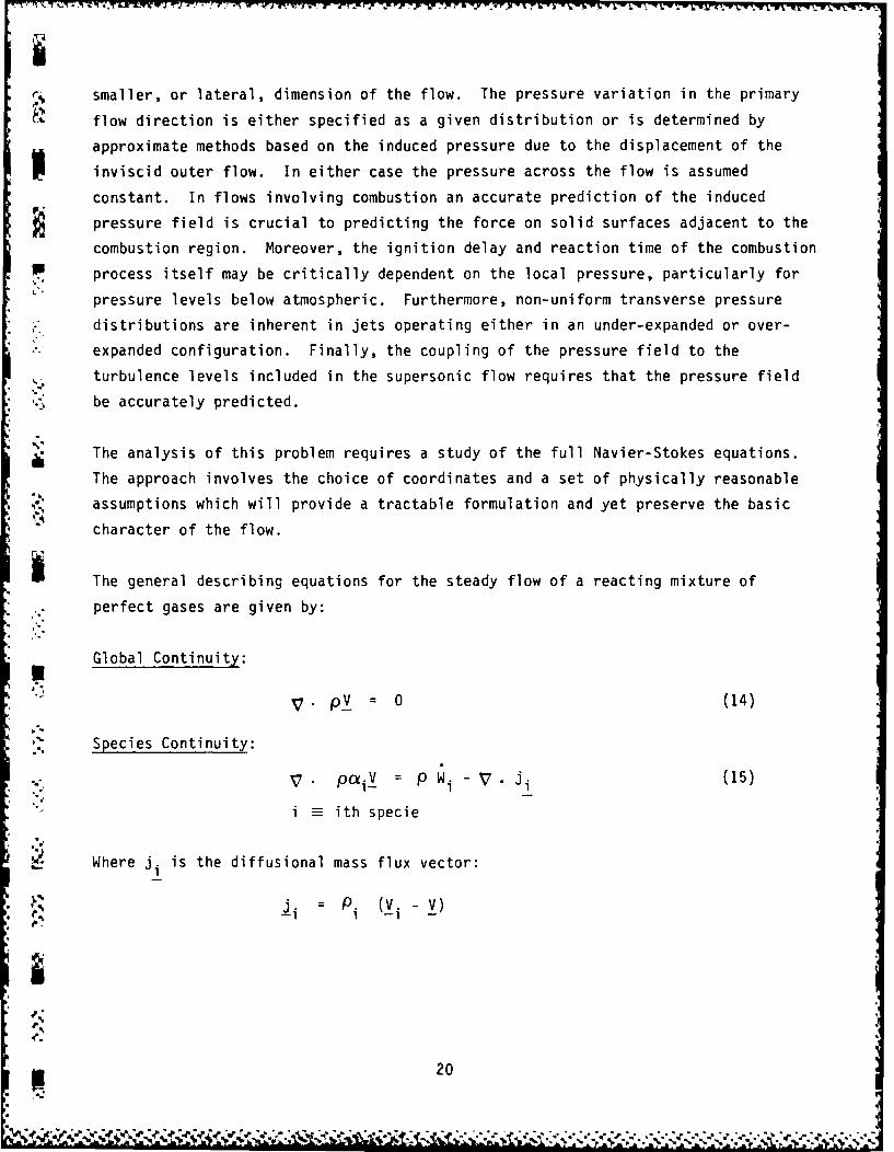
r% smaller, or lateral, dimension of the flow. The pressure variation in the primary
flow direction is either specified as a given distribution or is determined by
approximate methods based on the induced pressure due to the displacement of the
inviscid outer flow. In either case the pressure across the flow is assumed
constant. In flows involving combustion an accurate prediction of the induced
pressure field is crucial to predicting the force on solid surfaces adjacent to the
combustion region. Moreover, the ignition delay and reaction time of the combustion
1P process itself may be critically dependent on the local pressure, particularly for
pressure levels below atmospheric. Furthermore, non-uniform transverse pressure
distributions are inherent in jets operating either in an under-expanded or over-
expanded configuration. Finally, the coupling of the pressure field to the
turbulence levels included in the supersonic flow requires that the pressure field
be accurately predicted.
S The analysis of this problem requires a study of the full Navier-Stokes equations.
The approach involves the choice of coordinates and a set of physically reasonable
assumptions which will provide a tractable formulation and yet preserve the basic
character of the flow.
* The general describing equations for the steady flow of a reacting mixture of
. perfect gases are given by:
Global Continuity:
V (14)
Species Continuity:
Pa paV P pW -V ji (15)i1
i ith specie
Where j. is the diffusional mass flux vector:
"i : P. (V. - V)
20

IS Momentum:
V. P VV - P _ (16)
Where T is the viscous stress tensor.
Energy:
V'.VH = V . (T • V) - _q - V • Ji (17)
v vWhere H = .h. (T) + is the stagnation enthalpy, and q is the heat
1 1 1 2conduction vector.
State:[)= P
RT i (18)
RTZ W
Transport Processes
The transport processes considered in this investigation include viscous stresses,
, , species diffusion and heat conduction. The models used to represent these processes* N are as follows:
Vicous Stress
T : 2/ E- 2/3 /L 6 : e 6 (19)
SWhere
E= 1/2(VV +V * V) (20)
and 6 is the unit tensor.
-: Species Diffusion
The diffusion of each species is assumed to depend only on the gradient of the
particular species mass fraction. This assumption requires equal binary diffusion
j coefficients Dii, for each species so that Fick's law is applicable.
21

o. Under this assumption the diffusional mass flux is given by:
-D* Vol e 1. (21)i i = - pP ij ~ i
Heat Conduction
r Consistent with the above assumptions the heat conduction may be represented
by the Fourier law given by:
C= - k VT p P 4VT (22)
Pr
where
p i
A schematic of the coordinate system adopted in this analysis is shown in
Fig. 5. A coordinate system is sought wherein a minimum of physical assumptions
are required to simplify the Navier-Stokes equations and within which a numerical
solution is most easily formulated and implemented. The implicit coordinate
system provides these desired conditions. Some insight into this choice is
obtained by considering the important case of an underexpanded (or overexpanded)
jet. The initial flow deflection is governed almost entirely by the adjustment
of the pressure. The jet flow is separated from the external flow by the "dividing"
streamline and the gradients in velocity, concentration and temperature will be
greatest in the direction normal to the streamline. Of course, as the flow becomes
* more parallel to the jet axis this condition is still satisfied. It appears then
that in this coordinate system some of the usual boundary-layer assumptions may
..-. be applied. Furthermore, it is shown later that a natural consequence of this is
a characteristic method of solution which can be implemented with a certain degree
of ease.
Edelman et al., Ref. 16 (1968) have made a systematic order of magnitude analysis
in the s-n coordinate system (direction along and normal to a streamline) for Eqs.
(14) to (22) for both two-dimensional and axisymmetric flows. The problem involves
a class of supersonic jet flows having a principal flow direction which are
conditions also found in practical configurations including rocket nozzles and
supersonic combustion ramjet engine combustion chambers. in a supersonic flow,
small deflections can induce a non-uniform pressure field which can have a
22
o *.

4 I-
a)
0.4 LJ
V) 4-0
Or 4-)
F- E
>< -o
U+-
233
%0

w* W., P.. . . . . .. .-. -:. . . . . . . . . 4. rz-
significant effect upon combustion and pressure forces on surfaces adjacent to the
C flow. Furthermore, if the flow curvature is small in regions where viscous effects
dominate across the entire field, viz., away from the near region of an under-
expanded jet, then boundary layer type approximations are applicable to the diffusive
terms in the describing equations. They have shown that Eqs. (14) to (22) can be
reduced to the following simple form.
Global Continuity:
(pq)s +- j -r sin 0+ (pq)n = 0 (23)
s-Momentum:
[, 1rj (24)pq (q)s +Ps = r tOn n
n-Momentum:
2pq2)s + Pn = 0 (25)
Species Continuity:
p q (i)s= pWa + r r j L i n (26)
pq s 1 r3 I r j Fr inn
Energy:
pq (H) - r Pr n+ 1 (1 -1 ) (q2/2)
+ 1[ (Le-1) r j Pr h (CI.)n (27).Pr Ir( n
Where:
H C1. h. (T) + q22 (28)
24
.. '1

iN and
P (29)
RT Wi
3 In equations (23) - (29), the subscript notation has been used to indicate
partial derivatives, i.e.,
(pq)s s (pq)"',~~ [r j pH] - a J H]
ri H
The solution technique applied to equations 23 through 27 involves the couplingof both hyperbolic and parabolic equations. It is the purpose of the followingdiscussions to describe the details of the method of solution which can bedescribed in terms of an "inner" calculation (characteristics) and an "outer"
calculation (mixing).
The characteristics calculation is initiated in a standard manner from a "line"
l i of given data as shown in Fig. 6.
". . The characteristic directions are dependent only upon the local state and the left
(I) and right (II) running characteristic directions from point K, say, are given
by:
'Tan (30)
• , Wheredh (T
~ 2,F F=T (
Fi T i dT (31)
I . and all properties are evaluated at the point K.
. ... 25
Em
I iq,,, , ,~~~~~ ~~ ~ "- p, 2 W 'p. - ,, . - . , , . , , . . . , .- " ".,. -.. -. , . . . . . - . . , . . .

ii
VV
-
t
>< u
0S-
L4-
0..Il
L)~
.-J C C.)
A\ 1 - S
CC J
a a -
-(\ 9- 0
'4 C-4=.
><0
26~
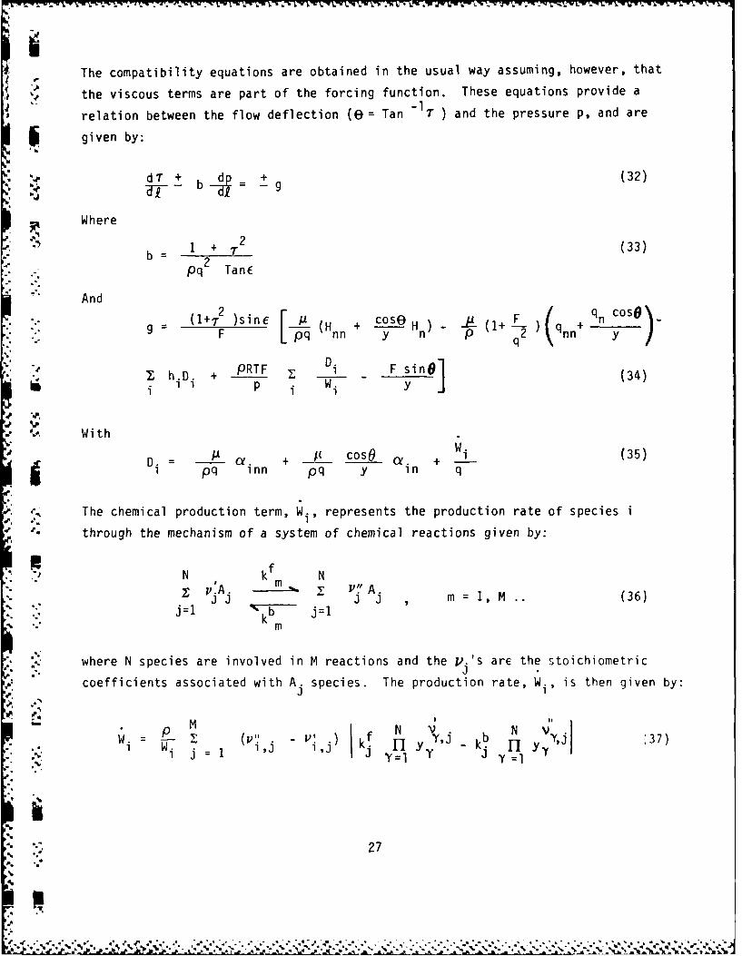
F i The compatibility equations are obtained in the usual way assuming, however, that
the viscous terms are part of the forcing function. These equations provide a
relation between the flow deflection (E)= Tan "T1) and the pressure p, and are
* , given by:
d + bd + (32): - b = -
Where
-" b= +_ _2 (33)
Pq TanE
* -'" And
(1+.2' .nF (Hnn + cOS Hn ) - -p (1+ L q+ q n CS)
9 g F oE) nn y n P q2 nn
I -D PRTF I Di F yi (34)I I p Wi y(4
.1 %P'. With
p i + cosO + Wi (35)I q inn pq y in q
The chemical production term, Wi., represents the production rate of species i
through the mechanism of a system of chemical reactions given by:
N kf N'- pA. m 2: P-. A.
m
- , where N species are involved in M reactions and the V.'s arE the stoichiometric
coefficients associated with A. species. The production rate, Wi, is then given by:
M Nf V. Vw - (V IN b N 3
,i W i =1 J -' Y k-- I 1 Y37)N. j : ' J JY=l 'Y Y =1
27

IWhere
1 (38)
is the molar density of the i th specie.
The sequence of calculations is initiated with a characteristic type calculation.
Referring to Fig. 6, the up-running characteristic from point K-I and the down-
running characteristics from point K are constructed and their point of inter-
section, CK, is obtained. This procedure is carried out for all intersectionspK
across the field. The minimum forward distance required for an intersection
determines the "characteristics" step size which guarantees that all new data
computed across the field is within the domain of influence of the initial data.
. The next step in the sequence of calculations involves the solution of the
compatibility equations along the characteristics. The differenced form of Eqs.
(32) are given by:
TC K-1 + bk_ 1 P- PK-1 = K-1 (39)
I I
and,
pC K b C : gK (40)
II-
Where
(x - x- + (YCK - 2 (41)
and,
i:!" : I (II (xCK - XK + (YCK YK (4?)
28
, *% ,Y . ' V'' .-

iSolving Eqs. (39) and (40) for the pressure gives:
A b + b" K- 1 "'K + gK- 1 AI II bK' 1 K-IPK-1 KPK(3
bK-i + bK
C is determined by substitution into either Eqs. (39) or (40).
As discussed above, a single forward step size is used and this is done in
anticipation of the subsequent mixing calculation discussed below. However,
this requires interpolations for the data required at points A, D and finally
E (Fig. 6). Thus, the pressure, p, and flow deflection, T, are determined at
A and D by interpolation along the characteristics and then a second interpolation
is performed across the field to determine p and T" on the streamline at point E.
In this way, the pressure gradient along the streamline is obtained:
ds PEK PKa YsK (44)
.-. s
. This result is utilized in the mixing calculation discussed in the next section.
S The explicit bilateral coupling between the pressure field and the viscous mixing
process is through the forcing function g in Eqs. (39) and (40) and the momentum
equation along the streamline, respectively. The former contains the diffusion
and chemical reaction terms and the latter contains the pressure gradient.
p. Furthermore, the description given above for the p-T determination represents a
single calculation in an iterative calculation. Thus, the forcing function is
modified by averaging it over a step which includes the "new" diffusion contributions
obtained at the end of the mixing calculation. The p-T'calculation is repeated
until the difference in two successively determined pressures is less than a
prescribed tolerance.
The calculation procedure as described so far lends itself uniquely to the appli-
cation of already existing numerical solutions of the parabolic mixing problem.
The solution is obtained by an explicit finite difference representation of the
describing equations along the streamlines. These equations are given by:
29
el d:t '.rP'.

N Momentum:0s )On On
pq 0 5 - p1 as qn gcoso ay -) (45)
2Energy:
- " /cos8 + aLOH (46)
aOns an On
Species: Or c+". /cosO / i
1.q + + a- + pw (47)a s (-n2 y a n -a n i
Turbulence:
One-equation TKE model
"e _g _e e +ose a2pe 2(pq S O +2 (/+Lcos On On (48)
Two-equation TKE model
a2 = e + coso ae +A(_q2 pPq Os Fk On 2 +--..) , an -p (49)
____ O _ / l2i+ cos9 + O Pe 2C
p. as = a 2 -L +2 + + (_2_ En -1L (50)s E a2y a n e an e
It is important to note that the describing equations for mean quantities have
been simplified from their most general form by the assumption that the Prandtl
* and Schmidt numbers are unity. Furthermore, in the numerical representation of
the above equations it is assumed that n -y. Both of these approximations were
made to facilitate the initial stages of the program development but it is believed
,. that the limitations are not critical.
To illustrate the numerical solution technique, consider the difference form of
Eq. (45) with reference to Fig. 7.
30

STEP SIZE
. M + 1.i ,.M
- )
.5 M
M I
Figure 7. Numerical Grid for Mixing Step.
.
- -
JI
5'
-, 3 1
W

q ~~-qmn qm+1,n - 2q m ~ ,qm-
' s p -q n ( y) 2 ' $m,n
''-L(51)
p coso mn Pm,n + Pm+l n - m-1,n (m+ln-qm-ln)]_ 1 ) Ap% YM 2,Ay 2,A yna
where 4P is given by the characteristics calculation (see Eq. (44).U
Eq.(51) represents an explicit finite difference form of the s-momentum equation.
-: The energy and species conservation equations assume a similar form. The forward
step size is limited by a stability requirement which for linear parabolic equations
is given by:
AyAs < 1/2 pq (52)
To insure stability of the non-linear system a fraction of the characteristic step,
" CF, is used:
+ N( +1) Ns (53)
. where N is an input integer. In cases involving fast reacting systems N =6 hasS S
* been found to be sufficient.
The species conservation equation, Eq. (47), is treated in a special way for configu-
rations involving finite rate kinetics. The equations for turbulent kinetic energy
e and dissipation rate E are also treated differently to avoid negative values
* . which are unphysical. In the beginning of the calculations when both diffusion
"* and production are negligible, the dissipation term (last terms in Eqs. (48) and
S1" (50) when expressed explicitly in the finite difference representation can give
negative values for e and E under certain circumstances. This is avoided by partly
implicitizing the dissipation term. Thus, e and E in the dissipation term are
approximated as (em,n+I ) (emn) and ( mn+) ( E respectively. Thus Eq.
32

VV
(48) can be approximated as:
emn+1 = emn + Xmn / 1 + Vs a2 emn (54)
qm,n I k
where Xm,n represents the diffusion and production term.
The above discussions pertain specifically to the solution technique for the
describing partial differential equations. To completely specify a given problem
* the initial and boundary conditions must be given. In the present report a shock-
less ducted jet flow configuration is described. The wall is assumed to be
impermeable, and adiabatic. The boundary conditions are given by:
r )
x > 0 ,y =y (X) aH 0 (55)w ay )w_ ___(5
1- 2 ( mean
The arbitrary wall contour, y = yw (x) may be specified in terms of the coefficients
. of 5th order polynominals covering four adjoining regions:
s n. ax (56)
40 n
The pressure is determined from the appropriate uprunning characteristic since
the flow deflection at the "new" wall point is known from Eq. (56).
The calculation proceeds as follows (see Fig. 8):
A characteristic step is taken to determine the minimum forward distance, CY, for
intersections. A star, point is found by interpolation between the w and KTSn npoints whose uprunning characteristic intersects the wall at the end of the step,
X n+1= xn . The pressure at the wall is then computed through the compatibility
:.
• 33
N-

. W N + 1
W- N
STA R P O INT -"-
b- KT -1
-N +
, N+I
Figure 8. Wall Interaction.
3
_ 34

INW 1VrJ w~w W -W 7y Y_'V IV W(i j" W -WI X AN., %J4 K. ~' "-
1equation:
= + * n + g*_, y* )57Pn+1 n n1 b*n n1 n(7
n
The remaining properties along the n+1 line are determined and the diffusion
calculation is performed. The wall boundary conditions for the diffusion step,
Eqs. (55) are imposed by inserting a data point above the wall denoted by KT+I.
- The numerical difference form of Eqs. (55) are then given by:
ai. = a.- 1 IKT+1 1KT
H KT+1 H KT (58)
qq c f (Pq) mean". qT+I qKT 2 ,(YKT+I-YKT)
where the physical location of the KT+1 point is given by:
YKT+1 Yw - YKT
Finally, the iterative process between the characteristic step and the diffusion
step is performed as described before.
This analysis has been applied to a jet flow configuration bounded by a parallel
wall. This configuration is basic to many fuel injection problems. The results
for an underexpanded all-supersonic ducted jet with Pj'Pe = 2 and with hydrogen
. (primary flow) exhausting in air (secondary flow) are presented in this section;
initial conditions for this calculation are given in Table 1. Two sets of
calculations have been carried out; one set with a constant eddy viscosity and
the second set with a viscosity computed by the two-equation TKE model. Figs. 9a
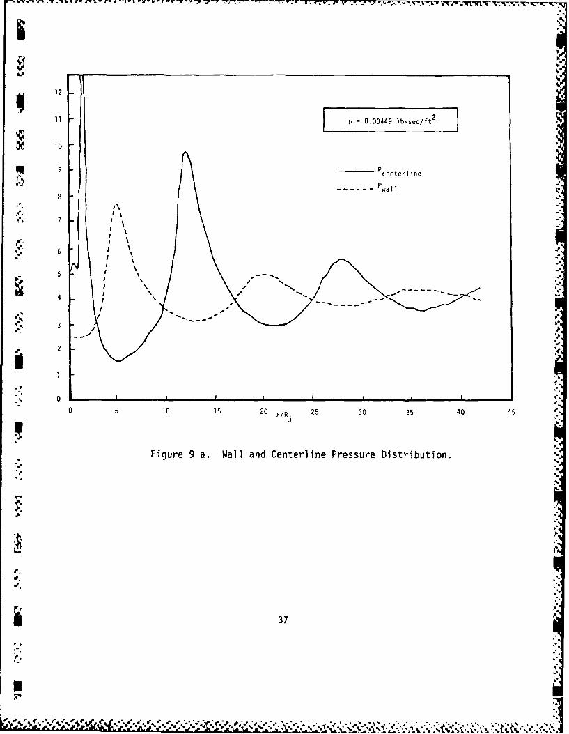
through 9f show the results of the first case where 1A 0.00449 lb-sec/ft waschosen. ihis is a rather high value for the viscosity and the results refleLt
' this fact. Figure 9a shows the wall and axis pressure distribution up to
x/r.= 44. The initial rise in pressure on the axis is related to the value of
3
"," p'". "35 ? : '" ,' 2 ,- % % -.- ';., . .,, .... -'' , ,.. . . ..-- ."- -. '-.., .. , , - .- '-: --

TABLE 1.
INITIAL CONDITIONS FOR SAMPLE CASE
AXISYMMETRIC HYDROGEN INJECTION INTO AIR STREAM
Stream Mach No. Velocity Pressure Temperaturei( gt/sec ) (LBF/gt2 ) (0k)
,. Air 3.375 8333 5290 1500
Hydrogen 2.032 16,634 10,580 1100
1
a,
I.
36
A. **¢ *~~ .*- *
11i 0.00449 lb-sec/ft 2
10
8
.. 7
Ile' 6
3
2
0
0 5 10 15 2 /. 25 30 35 40 45
Figure 9 a. Wall and Centerline Pressure Distribution.
p.
37
A%

I-
0
£4-)
0) (A6 LA
~CL)ON 0
C) >1
C0 4-
.0
1-
.1 N
38
L a 2167

8.85
8.80
8.75
0.00449 lb-sec/ft
8.70 10 1.0 2.0 3.0 4.0
* ,x/R
Figure 9 c. Pressure Profile at x/R= 40.6.
8.38 3
8.37
*8.36
": 8.35
. 8.34
* , 8.33
8.32
8.31 I .'0.00449 lb-sec/ft 2
8.30 I I I I 10 0.5 1.0 1.5 2.0 2.5 3.0 3.5 4.0
Y X R
Figure 9 d. Velocity Profile at x/R.j 40.6.393

4-).
4-'4
0n C 0
CN 0
0L C) '~
oC
U-)0 S
Ii * (
C)J u
- 0
-' 0
It 00
LA9'
(4-0

-" viscosity and the initial pressure ratio. Later with the adoption of the two-
equation TKE model this sharp rise disappears. The axial decay of hydrogen mass
fraction is shown in Fig. 9b. Because of the high viscosity the decay is almost
immediate with no potential core formation. Again, later we shall show that this
shortcoming is eliminated by the use of the TKE model for turbulence prescription.
Figures 9c to 9f show the profiles of pressure, velocity, temperature and hydrogen
mass fraction at x/rj = 40.6, which are typical of a well mixed flowfield.
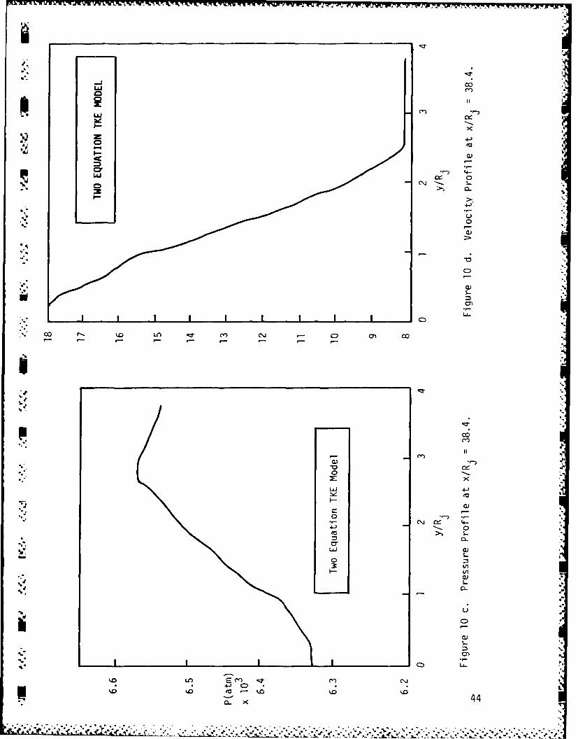
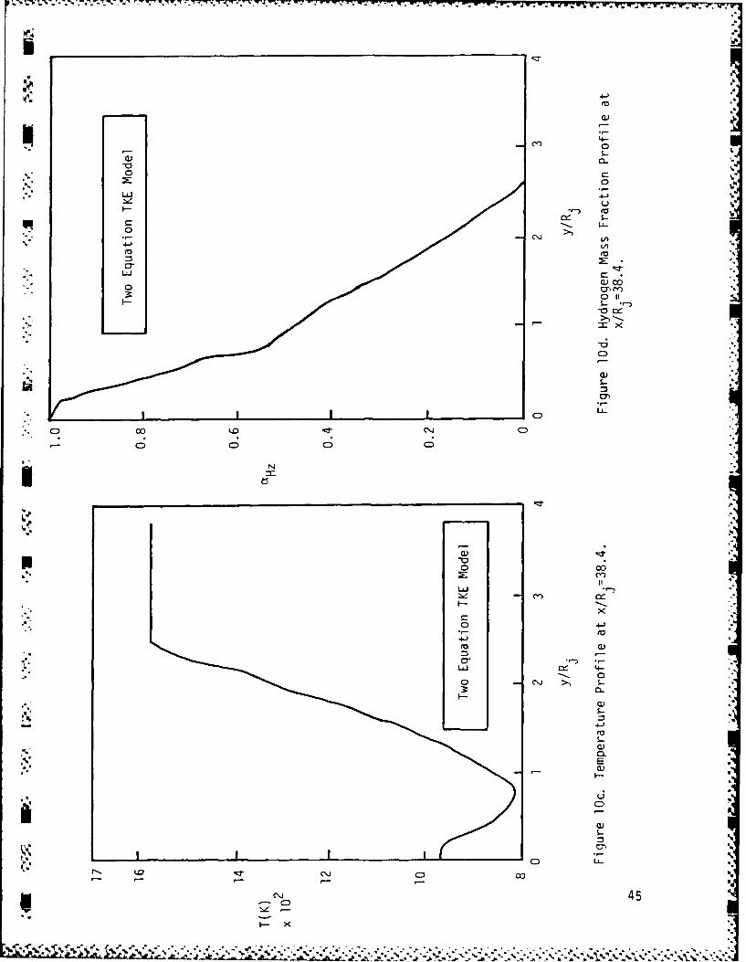
". Figs. 10a to 10f represent the flowfield for similar initial conditions and geometry
but with the constant viscosity replaced by the two-equation TKE model. Fig. 10a
shows the distribution of wall and axis pressure. The initial sharp rise in the
centerline pressure present in the previous case goes away with the adoption of
this turbulence model. Fig. lOb shows the axial decay of hydrogen mass fraction.
Based on this the potential core length can be estimated to be approximately 20
jet diameters. Figs. lOc to lOf show the profiles of pressure, velocity, temper-
ature and hydrogen mass fraction at x/rj= 38.4, which in general show that the
. width of the pressure field is substantially greater than the spread of the viscous
region.
* The results of these calculations show the possibility of the development of
relatively large pressure gradients in supersonic combustor flows. The sensitivity
*: *Y. of the induced pressure field to turbulence model assumptions is also demonstrated
by these results. However, conventional turbulence modeling was used in this
analysis and the direct effect of the pressure gradient on turbulence level was not
included in these calculations. Furthermore, the explicit effects of pressure
fluctuations on the turbulence was also neglected in these baseline calculations.
These pressure coupling effects are the key elements that have been previously
cited in this report as requiring inclusion in the analysis and the results of the
Preliminary calculations indicate that the induced pressure gradients can play a
significant role in the turbulence-pressure interaction phenomenon.
Because reacting flow is the ultimate application of the research to be carried
' _,.' out in this program, the chemical kinetics of the reaction process must also be
considered in the analysis. Short residence times and relatively low pressures
such as are encountered in a scramjet, increase the importance of chemical kinetics
41
-% & o? :. . ~ : ~ q-

4q
00
*.U
S.-
0 c
S.-
4-
AIn
/ C
J -oCDC
4 42

C)
S.-UL-
* to
-CU
-o
ci
o 4-
I.- C.)
* 43
C 0
'4o
LJ
4-zm
CD' '. CL
4-
L-
C-
* co N. m. LAj C). m co
'-4-
PCC.1)
LUJ 4-)
f--
-S-
o% o- .C
0)-- 0-
0 UA-
Ca.4 4-
XU
%0
W7 vIIl W; Ir rj w r W-. W-1 .
- C-
LL)
4. .-) 'V
.0 CYJ C,,
F- S- *-
C)
S..
LL-
00 000
NL
Xp
I..7
6' LLJcl a)
o0
4-4
'V a)
9-- a
0) 6
-~ 45)
Ca)
x0

effects in a scramjet relative to what is observed in subsonic combustors. At
the same time, turbulence-chemistry effects also become important. The analysis
of the interaction between turbulence and chemical reaction rates is a subject
of considerable current interest, but no tractable approach for including a
general and detailed finite-rate kinetics model in the analysis of turbulence-
combustor interactions has yet been developed. Although the relatively small
pressure fluctuations and pressure gradients strongly affect the turbulent
kinetic energy balance their influence on chemical kinetic rates needs to be
determined. Thus, as a first step in the consideration of all of the effects
involved in turbulent mixing and reaction in a supersonic flow, a fast-chemistry,
probability distribution function closure for the reaction problem should be
used. However, stronger pressure gradients can be used to control the combustion
process in a supersonic flow, and these will also affect the mixing process. Thus,
an assessment of the effects of pressure gradients and pressure fluctuations in an
environment where chemical kinetics effects are important must also be considered.
i if
46
44

4.0 PROFESSIONAL PERSONNEL
The following personnel have contributed to the work conducted on this pr3ject:
Dr. R. B. Edelman.w, Mr. W. N. Bragg
Dr. K. T. Wu
Dr. M. Y. Bahadori
I.
10
Os'4
4 7 ,

ii 5.0 INTERACTIONS
The sudden expansion (dump) combustor work carried under the task outlined in
Section 1 involves interactions with personnel in the Ramjet Technology Branch
(RJT) at AFWAL/PORT, Wright-Patterson Air Force Base.
Z4% , In addition, Dr. Edelman chaired the JANNAF workshop entitled "Turbulence in
Ramjet Combustors" held in conjunction with the 22nd JANNAF Combustion Meeting,
7-10 October, 1985 in Pasadena, California. The objective of this workshop wasto provide a link between current basic research on turbulence to problems in
ramjet combustion and to foster the utilization of relevant information on
turbulence in the design of ramjet systems. The discussions were largely
devoted to the role of large scale structures in turbulent mixing and combustion.
Both computer simulations and experimental work were presented and discussed at
the workshop.
.. 4!
hI-
48
REFERENCES
1. S.F. Birch and J.M. Eggers, "A Critical Review of the Experimental Data forDeveloped Free Turbulent Shear Layers", Free Turbulent Shear Flows, Vol. I -Conference proceedings, NASA SP-321, 1973, pp 11-40
2. Free Turbulent Shear Flows, Vol. II - Summary of Data, NASA SP-321, 1973, P.14.
3. P.T. Harsha, "Free Turbulent Mixing: A Critical Evaluation of Theory and4. Experiment", AEDC-TR-71-36, February 1971.
4. G. Brown and A. Roshko, "The Effect of Density Differences on the TurbulentMixing Layer", Turbulent Shear Flows, AGARD-CP-93, January 1972, pp. 23-1 -23-12.
5. P.Bradshaw, "Compressible Turbulent Shear Layers", Annual Review of FluidMechanics, Vol. 9, 1977, pp 33-54.
6. Y.H. Oh, "Supersonic Free Turbulent Mixing Layers", T rbulent Mixin inNonreactive and Reactive Flows, S.N.B. Murthy, ed., Pienum Press, 1975, pp 327-
• , 331.
7. O.M. Phillips, "On the Generation of Sound by Supersonic Turbulent Shear Layers",
Journal of Fluid Mechanics, Vol. 9, Part 1, 1960, pp 1-28.
8. J.P. Dussuage, J. Gaviglio and A. Favre, "Density Changes and TurbulenceProduction in the Expansion or Compression of a Turbulent Flow at Supersonic
* Speed", Structure and Mechanisms of Turbulence II, H. Fiedler, ed., LectureNotes in Physics, Vol. 76, Springer-Verlag, Berlin-Heidelberg-New York 1978,pp 385-395.
9. P.A. Libby and K.N.C. Bray, "Countergradient Diffusion in Premixed TurbulentFlames", AIAA Journal, Vol. 19, No. 2, Feb. 1981, pp 205-213.
10. W.C. Strahle and S.B.S. Chandra, "Pressure-Velocity Correlation in a ReactiveTurbulent Flow", AIAA Journal, Vol. 20, No. 1, Jan. 1982, pp 129-135.
11. S.M. Correa, "Prediction of an Axisymmetric Combusting Flow", AIAA Journal,Vol. 22, No. 11, Nov. 1984, pp 1602-1610.
* 12. N.M.Komerath and W.C. Strahle, "Measurement of the Pressure-Velocity Correlation* in Turbulent Reacting Flows", AIAA Paper 83-0400, 1983.
" 13. Rotta, J.C. (1979) "Eine theoretische Uutersuchung Uber den Eiufluss derDrucksherkorrelationen auf die Entwicklung driedimensionaler turbulenterGrenzschichten" DFVLR-FB-79-05, Deutsche Forschungs-und Versuchbaustad +fur Luft-und Raumfahrt.
14. Hanjalic, K., Launder, B.E., and Schiestel, R. (1979) "Multiple-Time-ScaleConcepts in Turbulent Transport Modeling" Paper presented at Second Symposiumon Turbulent Shear Flows.
49
N N.4 I
h
15. Fabris, G., Harsha P.T., and Edelman, R.B. (1981) "Multiple-Scale TurbulenceModeling of Boundary Layer Flows for Scramiet Applications", NASA CR-3433.
16. Edelman, R., and G. Wilerstein., "Mixing and Combustion in Supersonic Flow withLateral Pressure Gradient Effects", GASL TR No. 636, August 1968.
-50
,'
i
" 'i,50
.°° ° . .o ... - , , , . . o .°• o .- . °°o •. . ., . . . . . . . . . - • . .

* ..