meecl chakresh report utm shillong
TRANSCRIPT
1
A REPORT ON INDUSTRIAL VISIT TO
Ri-Bhoi District,Meghalaya
ON
2TH April 2015
UNDER THE AEGIS OF
UNIVERSITY OF TECHNOLOGY & MANAGEMENT
SHILLONG,MEGHALAYA(793001)
Submitted To : Submitted By :
MS. Pronami Bora Chakresh Tiwari
B-tech ECE 4th sem.
Roll No. : R020113004

2
CONTENTS
Sr. No. Title Page No.
1. Acknowledgement 3
2. Overveiw of The Company 4
3. Technical Data 6
4. Mission & Vision 7
5. Technology & Certification 8
6. Methadology 9
7. Water Level 10
8. Plant Details
11
9. Conclusion 16
10. Bibliography 17

3
ACKNOWLEDGEMENT
I have gained a lot of knowledge during industrial visit at Meghalaya
Energy Corporation Limited. I would like to express my gratitude to all those who
gave me the possibility to complete this project. I want to thank UTM Shillong for
giving me the great opportunity to commence this industrial visit .
I am grateful to Mr. Laari (Working as a counselor in MEECL). Under
guidance, I have completed this Industrial Visit . I have no words to acknowledge
the valuable time & support that I have received from him.
4
Overview Of The Company
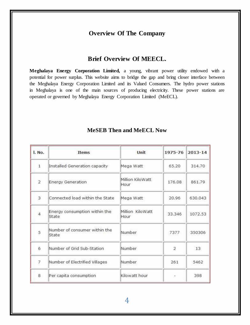
Brief Overview Of MEECL.
Meghalaya Energy Corporation Limited, a young, vibrant power utility endowed with a
potential for power surplus. This website aims to bridge the gap and bring closer interface between
the Meghalaya Energy Corporation Limited and its Valued Consumers. The hydro power stations
in Meghalaya is one of the main sources of producing electricity. These power stations are
operated or governed by Meghalaya Energy Corporation Limited (MeECL).
MeSEB Then and MeECL Now

5
Availability of Power in MePDCL
Year Unrestricted Peak
Demand (MW)* State Generation
(MU) Power Purchase
(MU) Total
Availability
(MU)
2004-05 220 635.35 757.96 1393.31
2005-06 280 514.44 871.66 1386.10
2006-07 350 389.09 929.30 1318.39
2007-08 385 663.06 924.15 1587.21
2008-09 352 552.84 968.92 1521.76
2009-10 339 534.79 947.29 1482.08
2010-11 289 507.90 1129.15 1637.05
2011-12 373 517.54 1170.54 1688.08
2012-13 381 704.55 1056.78 1761.33
2013-14 396 861.79 1028.76 1890.55
Note: * Unrestricted Peak Demand is based on the (Connected Load *0.85 * 0.6)
The development of the Power Sector in the state of Meghalaya is presently moving in the right direction so that the availability of affordable, reliable and quality power is ensured to the people
of the state in the near future.
Understanding the importance of Power as a prime mover for the development of the State, the Government had initiated a number of measures to develop the state power sector to its fullest potential for the prosperity of Meghalaya and its people.
In the past, there has not been any proper power development planning and this has resulted in making Meghalaya a power deficit state.
The government feels that the vast hydro potential of about 3000 MW needs to be harnessed at the earliest. Thrust has been made in the development of infrastructure of the transmission network, so
that the state can evacuate its future generation surplus and also to eventually draw its share of power from the Central Power sector in the North East region. There is an intention to explore and
possibly tap the power potential of up to 400MW from small hydropower generation alone.
It is hoped that in the near future the state of Meghalaya will once again regain its status of a power surplus state.

6
Technical Data.
Feederwise Distribution Transformers as on 31.10.2009
Name of the 33/11KV Sub-station:- Ampati
No. 33/11KV Transformer:- 2.5MVA X 1
No. of Outgoing Feeder:- 4
Ampati feeder-I
1. 100KVA X 3 2. 63KVA X 14
3. 25KVA X 64 4. 16KVA X 6
5. 10KVA X1 6. 5KVA X1
Ampati feeder-II
1. 100KVA X 1 2. 25KVA X 5
Kalaichar feeder
1. 100 KVA X 1
2. 25 KVA X 18 3. 63 KVA X 4 4. 16 KVA X 1
Jangnapara feeder
1. 63 KVA X 1
2. 25 KVA X 7
Name of feeders 5KVA
10KVA
16KVA
25KVA
63KVA
100KVA
200KVA
1) Ampati 1 1 6 64 14 3
2) Ampati DC Office
Complex 5 1
3) Kalaichar 1 18 4 1
4) Jangnapara 7 1
Total 1 1 7 94 19 5

7
Vision & Mission
Vision Statement
Respect for the individual. The Three Joys (Production, selling and creating), increase power and energy production as well as to improve power generation efficiency in the state of
Meghalaya
Mission Statement
Maintaining a global viewpoint, want to see whole Area in Light with customer satisfaction. It is hoped that in the near future the state of Meghalaya will once again regain its
status of a power surplus state.
Existing Power Stations of Meghalaya Power Generation
Corporation Limited
Sl. No Station Type No of Units/
Capacity COD Capacity
(MW)
1 Umiam Stage-I
Storage/
Pondage
4*9 MW FY 1966 36
2 Umiam Stage-II 2*10 MW FY 1971 20
3 Umiam Stage-III 2*30 MW Unit 1: FY 1979 Unit 2: FY 1979
60
4 Umiam Stage-IV 2*30 MW FY 1993 60
5 Umtru Power Station
Run of River (ROR)
4*2.8 MW Unit 1-3: FY 1958 Unit 4: FY 1969
11.2
6 Sonapani HEP 1.5 MW FY 2010 1.5
7 Leshka HEP 3*42 MW Unit 1& 2:FY 2013
Unit 3: FY 2014
126
314.7

8
TECHNOLOGY
HSPP benefits from the rich experience of Honda Motors, Japan, the second
largest engine manufacturer in the world, because of their strong emphasis on
R&D and in-house technical innovation. India’s first LPG based Generator along
with the Super Silent Key Start Generator portable kerosene generators are some
of the products which exemplify Honda’s pursuit of technological excellence. The product range of Generators conforms to the most stringent phase II Noise &
Emission norms as laid down by the Central Pollution Control Board (CPCB),
Government of India.
CERTIFICATION
Govt. of Meghalaya (GoMe) decided to reform and restructure its power sector with the
objective of creating the conditions for the sustainable development of the electricity supply
industry and improving the efficiency and quality of services in Meghalaya. The ultimate goal of
reform process is to ensure that
a)Electricity is supplied under the most efficient conditions in term of quality and cost to support the economic development of the State; and b)The power sector ceases to be, through its Electricity Board, a burden on the State’s budget, and
eventually become a net generator of financial resources.
Govt. of Meghalaya after deciding to reform and restructure its power sector intends to corporatize its power sector and has also to establish an appropriate Electricity Regulatory Commission.

9
METHODOLOGY
Stage I (Sumer) hydro power station capacity 4 x 9 = 36 MW : (1)Operation of the power station
4 AE + 4 JE + 4 control room operation + 12 technician. However in stage I control room is two stories above the turbine floor. In-between control room
and turbine floor an intermediate floor where 11 KV switch panel are housed block the free passage. Therefore one JE per shift is at present necessary to coordinate between turbine floor and control room. Apart from that communication from all the power station toload despatch center is
now through the stage I power station since the direct link toload despatch center from other power stations have been disconnected, hence communication is also an added
responsibility of this power station which is borne by the special manning. As such operation manning at stage – I should be 4 AE + 8 JE + 4 control room operator + 12 technician.
(2)Maintenance of stage I
1 JE + 1 Electrician + 1 fitter + 6 technician + 1 crane driver Therefore proposed manpower 4 AE + 9 JE + 4 control room operator + 1 electrician + 1 fitter + 1 crane
driver + 18 technician. Total 38. Existing manpower 5 AE + 8 JE + 25 technician. Total 38.
Stage II (Umsumer) hydro power station capacity 2 x 9 = 18 MW.
(1)Operation of power station:
Same manning :
4 AE + 4 JE + 4 control room operator + 12 technician.
(2)Maintenance of stage 2:
Maintenance also should have the standard m anning of 1 JE + 1 Electrician + 1 fitter
+ 18technician + 1 crane driver.
.

10
Water Level at Umiam Reservoir upto 1st.April. 2015

11
About Plant
There are two big pipes are coming from a height ,they are full of water contain they are divided
into four parts due to which four motor connected for more electricity production then the water
falls on the turbine due to which turbine rotates so due to rotation of turbine Electricity produces.
Light is depends on the rotation of turbine and rotation of turbine is depends on the pressure of
water falls .
Main components of Power Plant
1. Power Plant Room
2. Switching room
Power plant
The power is the main source of any organization. That is the first requirement of any
organization is the input. The main source of this exchange is the AC supply. This act as the
feeding point of power to all other sections. To start every machine the first supply is from a dc
source, but it is not the main source of power supply. It is used only for the excitation needed by
the machine to start and then it is converted into ac power supply.
The equipments used in the power plant are :-
Sump tank
Emergency cooling machine
Immersing machine
Air compresser pump
Automatic voltage regulator
Service station transformer
Induction motor
Turbine
Generator unit
Power line communication carrier

12
Sump tank
It has two different coloured pipes connected to it. They are yellow and green pipes. The
yellow pipe contains oil and the green pipe contains water. When the machine starts it
pushesthe water further. It is automatically control.
Emergency cooling machine
This machine is used to cool down the temperature within the machine when it gets heated up. It is
handled manually. When the temperature inside the machine rises, the steer is rotated and cool
water is supplied around the part which becomes heated.

13
Immersing machine
This machine is used to maintain the water level to push it further. When the water is below the
level needed, then some weights are immersed to raise the water level to make it function. When
the water is above the level needed, like at times of rain or flood, the weights are taken out to
decrease the level of water.
Air compressor pump
It is used to maintain the pressure inside the container containing 10 kgs of air/vaccum and 20 kgs
of oil.

14
Automatic voltage regulator
The AVR (automatic voltage regulator) as the name suggests it regulates the voltage. It is set so to
reduce the work load the workers i.e. they don’t need to check the voltage on which the machine
works. It will automatically regulate as per the requirement.
Induction motor and turbine
The motor used was a 3 – phase induction motor. It consists of a stator and a rotor. It works on the
principle of electro-magnetic induction. The stator is made by joining many copper rings which
behaves like a hollow sphere. The wires are wounded in such a way that when the current passes
one part behaves as the north pole and the other as the south pole.
The rotor is the rotating electrical components, it consists of group of electromagnets arranged
around the cylinder with the poles facing the stator poles. It is located inside the stator. As the
magnetic field of the stator alternates due to the effect of ac power supply, the induced field of the
rotor gets attracted in.

15
The turbine is rotated only when water hits it with a pressure, it is connected to the generator
where the power is generated.
Generator room
There are many units of generators. Since a large amount of power is generated from the power
plant, therefore, a no. of units are there to keep a record of the power generated.
Power line communication carrier
They show the arrangement of line networks to supply power to various cities. The lining on the
top is for the main bus. The one below it is for the auxillary bus. Bus couplers are there which are
used in operating the machine from the power station if the machine has been transported
somewhere.
16
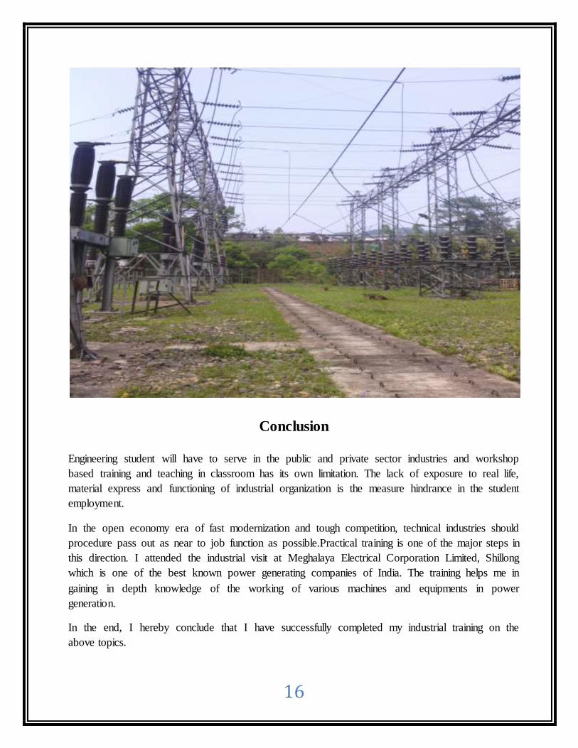
Conclusion
Engineering student will have to serve in the public and private sector industries and workshop
based training and teaching in classroom has its own limitation. The lack of exposure to real life,
material express and functioning of industrial organization is the measure hindrance in the student
employment.
In the open economy era of fast modernization and tough competition, technical industries should
procedure pass out as near to job function as possible.Practical training is one of the major steps in
this direction. I attended the industrial visit at Meghalaya Electrical Corporation Limited, Shillong
which is one of the best known power generating companies of India. The training helps me in
gaining in depth knowledge of the working of various machines and equipments in power
generation.
In the end, I hereby conclude that I have successfully completed my industrial training on the
above topics.

17
Bibliography:
http://meecl.nic.in/notifications.htm
http://meecl.nic.in/default.htm
http://meecl.nic.in/progressreports.htm
http://meecl.nic.in/history.htm
http://meecl.nic.in/network.htm
http://meecl.nic.in/waterlevel.htm