medium voltage ac drive – “c” frame - biap.com.pl · powerflex 7000l technical data guide 3...
TRANSCRIPT

Medium Voltage AC Drive – “C” Frame (Liquid-Cooled) Technical Data Guide


Table of Contents
7000 “C” Frame 7000L-TD200A-EN-P – September 2005
1.0 Overview of Drive ......................................................................................................................... 1
1.1 Introduction ......................................................................................................................................... 1 1.2 Benefits of Liquid-Cooled Drives ......................................................................................................... 2 1.3 Topology ............................................................................................................................................. 4 1.4 Rectifier Designs ................................................................................................................................. 5 18-pulse Rectifier ..................................................................................................................... 5 PWM Rectifier (Active Front End) ............................................................................................. 6 1.5 “Direct-to-Drive” Technology ............................................................................................................... 7 1.6 Motor Compatibility ............................................................................................................................. 9 1.7 SGCT Features and Benefits ............................................................................................................ 10 2.0 Control Overview ......................................................................................................................... 11
2.1 Direct Vector Control ......................................................................................................................... 11 2.2 Control Hardware .............................................................................................................................. 12 2.3 Operator Interface ............................................................................................................................. 13 2.4 Software Interface – Drive Tools ....................................................................................................... 14 3.0 Simplified Electrical Drawings .................................................................................................. 15 4.0 MV Drive Selection Explanation ................................................................................................. 17 4.1 Drive Service Duty .............................................................................................................................17 4.2 Service Duty Rating, Continuous Current Rating and Altitude Rating Code ..................................... 17 5.0 Drive Ratings – Product Selection ............................................................................................ 19
5.1 Normal Duty Rating for 18-Pulse Rectifier ........................................................................................ 19 5.2 Normal Duty Rating for PWM Rectifier with Integral Line Reactor .................................................... 20 5.3 Normal Duty Rating for “Direct-to-Drive” Technology ........................................................................ 21 5.4 Heavy Duty Rating for 18-Pulse Rectifier .......................................................................................... 21 5.5 Drive Options, Modifications and Accessories .................................................................................. 22 5.6 Tachometer Requirements ................................................................................................................ 26 5.7 Selection of MV Drive Structures ...................................................................................................... 27 5.8 Selection of Liquid-to-Air Heat Exchanger Structures ....................................................................... 27 5.9 Standard Drive Liquid-to-Air Heat Exchanger Combinations ............................................................ 28

ii Table of Contents
7000L-TD200A-EN-P – September 2005 7000 “C” Frame
6.0 PowerFlex 7000 “C” Frame Dimensional Drawings ................................................................. 29 7.0 Typical PowerFlex 7000L Drive Structure Layout .................................................................... 72
7.1 Control/Cabling Cabinet .................................................................................................................... 72 7.2 Major Components ............................................................................................................................ 72 7.3 Liquid-to-Air Heat Exchangers .......................................................................................................... 80 7.4 Liquid-to-Liquid Heat Exchangers ..................................................................................................... 84 7.5 Specifications .................................................................................................................................... 87 7.6 Typical Auxiliary Equipment .............................................................................................................. 90 8.0 Appendix A .................................................................................................................................. 94
9.0 Appendix B .................................................................................................................................. 95
9.1 Transformer Secondary Insulation Levels Table ............................................................................... 95 10.0 Appendix C .................................................................................................................................. 96
10.1 Critical Standards .............................................................................................................................. 96 10.2 Component Standards ...................................................................................................................... 96

PowerFlex 7000L Technical Data Guide 1
7000 “C” Frame 7000L-TD200A-EN-P – September 2005
1.0 Overview of Drive 1.1 Introduction The PowerFlex™ 7000L “C” Frame drive represents the third
generation of medium voltage drives at Rockwell Automation. The PowerFlex 7000L “C” Frame medium voltage AC drive is part of the PowerFlex family of AC drive products. The Allen-Bradley PowerFlex™ family of Drives incorporates leading-edge technology, embedded communications, and significant commonality across multiple platforms, networks, operator interface programming and hardware. Designed for end users, solution providers and OEMs, PowerFlex 7000L “C” Frame liquid-cooled drives meet applications ranging from 3000 to 9,000 horsepower (2240 – 6715 kW).
The PowerFlex 7000L “C” Frame drive is a general purpose stand
alone medium voltage drive that controls speed, torque, direction, starting, and stopping of standard asynchronous or synchronous AC motors. It is intended for use on a host of standard and specialty applications such as fans, pumps, compressors, mixers, conveyors, kilns, fan-pumps, and test stands. Primary industries for these applications include petrochemical, cement, mining and metals, forest products, power generation, and water / waste water.
The PowerFlex 7000L “C” Frame drive is a global product that
adheres to the most common standards from NEC, IEC, NEMA, UL, and CSA. It is available with the world’s most common supply voltages at medium voltage, from 3300 to 6900 volts.
The design focus is on high reliability, ease of use, and lower total
cost of ownership. For 3300V designs, contact the factory.

PowerFlex 7000L 2 Technical Data Guide
7000 “C” Frame 7000L-TD200A-EN-P – September 2005
1.2 The PowerFlex 7000L “C” Frame liquid-cooled drive utilizes a
closed loop system to cool the converter main power components and the integral DC link inductor.
The main benefits of liquid cooling include:
Smaller drive dimension compared to air cooled drives of similar rating
Higher power rating capability Quiet operation in control room Low loss rejection to the control room reduces air conditioner
loading Approximately 90% of the losses are rejected outside the control
room via a liquid to air or liquid to liquid type heat exchanger Liquid-cooled drives have a 23:1 better heat transfer ratio over
air-cooled drives. The main benefits of the 7000L “C” Frame liquid-cooled drive
include: Completely integrated MV drive package reduces customer
installation costs and start-up time. Higher power rating capability (up to 9000 hp / 6715 kW) 18-pulse and PWM rectifiers for low harmonic solutions that
meet IEEE 519 Harmonic Guidelines Motor friendly current and voltage output waveforms for use
with standard new and existing motors – Inverter duty motors not required – Motor temperature de-rating not required – No additional dv/dt or peak voltage stress to motor insulation
system – Tested up to 15 kilometer cable distance between drive and
motor Spacious cable termination cabinet for ease of use by installation
contractor Cable termination stabs accommodate:
– 3 cables in / 3 cables out ( 6 pulse or PWM with line reactor) – 9 cables in / 3 cables out (18-pulse) – Top or bottom entry and exit of line and load cables
90% of drive losses are rejected outside the control room Integral liquid-cooled DC link inductor reduces overall
dimension and eliminates external inter-wiring.
Benefits of Liquid- Cooled Drives

PowerFlex 7000L Technical Data Guide 3
7000 “C” Frame 7000L-TD200A-EN-P – September 2005
Integral pumping panel includes:
– Line supply c/w disconnect and fusing – Closed loop coolant system – Iron and chloride free liquid ethyl-glycol / de-ionized water
mixture – Low conductivity coolant (1-2 micro-Siemens / cm3) – Isolated from medium voltage – Fully serviceable low voltage compartment isolated from
medium voltage power – Monitors coolant temperature, flow, level, conductivity, and
pressure – Redundant pumping system – Automatic pump change over on pump failure – 1/2 turn valves with quick disconnect couplers for pump
replacement when drive is operating – Full drip tray to contain any spilled coolant – Drain and fill pump for convenient filling – Industrial schedule 80 CPVC piping for pump panel, headers
and manifolds (no condensation possibility) – Control hardware for cycling of main / redundant cooling
pumps and Heat exchanger fans – Internal non-pressurized cooling fluid reservoir
“Plug and play” Power Cage concept
– Central location for easy access to all main power components
– Common modular design for rectifier / inverter – Same concept as air cooled drive for front access, easy
component replacement, and no special tools – 5-10 minutes to replace main power devices – No need to remove any cooling lines for device replacement – Reduced manufacturing time for faster delivery and lower
cost Keyed mechanical interlock
– Interlocked with main disconnect means to prevent unsafe access to medium voltage section

PowerFlex 7000L 4 Technical Data Guide
7000 “C” Frame 7000L-TD200A-EN-P – September 2005
1.3 Topology The PowerFlex 7000L “C” Frame drive utilizes a Pulse Width
Modulated (PWM) – Current Source Inverter (CSI) for the machine side converter as shown in Figure 1.1. This topology offers a simple, reliable, cost effective power structure that is easy to apply to a wide voltage and power range. Power semiconductor switches are easy to series for any medium voltage level. Semi-conductor fuses are not required for the power structure due to the current limiting DC link inductor.
With 6500 volt PIV rated power semiconductor devices, the number
of inverter components is kept to a minimum. For example, only twelve inverter switching devices are required at 4160V and 18 inverter switching devices at 6600V.
The PowerFlex 7000L “C” Frame drive has the additional benefit of
inherent regenerative braking for applications where the load is overhauling the motor, or where high inertia loads need to be slowed down quickly. Symmetrical Gate Commutated Thyristors (SGCTs) are used for machine converter switches. Silicon-controlled rectifiers (SCRs) (18-pulse) or SGCTs (for PWM rectifier) are used for the line converter switches.
2U (X1)
2V (X2)
2W (X3)
SGCT’s
LINE CONVERTER DC LINKL+ M+
SGCT’s
MACHINE CONVERTER
U (T1)
V (T2)
W (T3)
L- M-
1U
1V
1W
LR
Figure 1.1 – PWM with Line Reactor (4160 Volt)

PowerFlex 7000L Technical Data Guide 5
7000 “C” Frame 7000L-TD200A-EN-P – September 2005
1.4 Rectifier Designs There are two designs for the front-end rectifier of the 7000L “C”
Frame drive. 18-Pulse Rectifier An 18-pulse phase controlled rectifier is shown in Figure 1.2. In an
18-pulse configuration, the IEEE-519 requirements are met, in the majority of cases, without the need for passive filters; however, a multi-winding isolation transformer is required to mitigate the low order harmonics by phase shifting principles. The 18-pulse solution is superior to 6-pulse or 12-pulse offerings in terms of lowering line side harmonics.
The isolation transformers are available in both indoor dry type and
outdoor oil-filled designs for maximum flexibility in dealing with floor space, installation costs, and control room air conditioner loading. (Refer to Specification 80001-005, Rectifier Duty Transformers, for more details on transformer requirements and features.)
The line current and voltage are also shown in Figure 1.2. The THD
of line current is approximately 5.6%, while the THD of line voltage (line to line) is approximately 2.0%. (THD of line voltage is a function of the system impedance.) The 18-pulse rectifier consists of one master bridge and two slave bridges and will always have a total of 18 SCR switching devices.
Figure 1.2 – 18-pulse Rectifier and its input waveforms
a) Line current b) Line-to-line voltage at PCC
a) b)

PowerFlex 7000L 6 Technical Data Guide
7000 “C” Frame 7000L-TD200A-EN-P – September 2005
PWM Rectifier (Active Front-End) An active front-end suitable for the PowerFlex 7000L “C” Frame
topology is called a PWM rectifier. This is particularly attractive for applications with new motors since it does not require an isolation transformer to meet IEEE-519. (See Specification 80001-004, Stator Insulation Requirements for MV Motors Applied to MV Drives without common mode voltage elimination). Most available technologies in today’s MV market require a multi-winding transformer to mitigate the unwanted harmonics through cancellation by phase shifting the transformer secondary windings. Depending on the topology, the transformer can have up to 15 sets of secondary windings. Elimination of the isolation transformer reduces capital and installation costs, saves on valuable floor space, and increases overall system efficiency.
The PWM rectifier requires a switching pattern that complies with
similar rules as the inverter. The pattern used for the example shown in Figure 1.4 is a 7-pulse selective harmonic elimination (SHE) pattern, which eliminates the 5th, 7th and 11th harmonics. The input capacitors are designed to reduce the current harmonics of the higher order. The filter resonant frequency is placed below 300 Hz where no residual harmonics exist. The filter transfer function technique is used to place the filter break frequency in a region where no harmonics are present. This prevents the excitation of system harmonic frequencies. Other factors that are considered when designing the filter are the input power factor and the requirement on Total Harmonic Distortion (THD) of input current and voltage waveforms.
The small AC line reactor (see Figure 1.3) provides additional
filtering and current limiting features to a line side short circuit fault. The rectifier input current, the rectifier terminal voltage and the line current and voltage waveforms are shown in Figure 1.3. The line current THD is approximately 4.5%, while line to line voltage THD is approximately 1.5%. (THD of line voltage is a function of system impedance.) Input power factor with the PWM rectifier is equal to or greater than 0.98 for the entire speed and load range when applied to variable torque loads.
The PWM rectifier can be used in conjunction with a rectifier duty
isolation transformer or with an AC line reactor (as shown in Figure 1.3).
1.4 Rectifier Designs (cont.)

PowerFlex 7000L Technical Data Guide 7
7000 “C” Frame 7000L-TD200A-EN-P – September 2005
Isolation transformers are available in both indoor dry type and
outdoor oil-filled designs for maximum flexibility in dealing with floor space, installation costs and control room air conditioner loading.
Figure 1.3 – PWM rectifier (active front-end) and its input current/voltage waveforms a) Line current b) Line-to-line voltage at PCC The PowerFlex 7000 with “Direct-to-Drive” technology allows you
to: connect supply power directly to the drive without an Isolation
Transformer and connect a new or existing motor directly to the drive without
extra motor filtering. Most Medium Voltage Drive Manufactures use multi-winding
isolation transformers to mitigate unwanted harmonics by phase shifting the transformer secondary windings. Depending on the topology, the transformer can have up to 15 sets of secondary windings. The disadvantage to this method is the high degree of drive complexity and a very high component count.
Manufacturers also use transformers to protect motors from
Common Mode Voltage stress. When transformers are used they allow the motor neutral point to be connect to ground, but with this method, the common mode voltage that would otherwise be impressed on the motor is impressed on the transformer. The disadvantage to this method is that increased transformer insulation and increased cable insulation is required between the transformer and the drive so it can withstand the common mode voltage stress.
a) b)
1.5 “Direct-to-Drive” Technology

PowerFlex 7000L 8 Technical Data Guide
7000 “C” Frame 7000L-TD200A-EN-P – September 2005
Rather than use an Isolation Transformer, the “Direct-to-Drive”
Active Front End uses semi-conductor switching to reduce line current harmonics to levels that comply to the worlds most accepted harmonic standards. The Active Front End is the best method of harmonic cancellation because it does not suffer from complexity and high component count like multi-pulse drive topologies do.
“Direct-to-Drive” technology produces almost no common mode
voltage so it is suitable for new or existing motors and imposes no stress on the drive input. The advantage of “Direct-to-Drive” technology over an Isolation Transformer is that no extra insulation is required in the motor, in the motor cables or in the line cables.
And, in addition to mitigating Common Mode Voltage, “Direct-to-
Drive” technology does not generate DV/DT or Reflected Wave Voltage Stress on Motors.
The simplicity of its design results in a lower initial capital
investment, lower operating cost, lower installation cost and lower maintenance cost relative to drives that require isolation transformers.
The PowerFlex 7000 with “Direct-to-Drive” technology is typically
smaller and lighter that drive technologies that use Isolation Transformers - Isolation Transformers represent 30 to 50% of a drive system size and 50 to 70% of the system’s weight. This means that there is no interviewing between drive and transformer (for external transformer configurations), and no shipping splits in the drive (for integral transformer configurations). This makes the PowerFlex 7000 the simplest to install.
1.5 “Direct-to-Drive” Technology (cont.)

PowerFlex 7000L Technical Data Guide 9
7000 “C” Frame 7000L-TD200A-EN-P – September 2005
1.6 Motor Compatibility The PowerFlex 7000L “C” Frame drive achieves near sinusoidal
current and voltage waveforms to the motor, resulting in no significant additional heating or insulation stress. Temperature rise in the motor connected to the VFD is typically 3°C higher compared to across the line operation. Dv/dt in the voltage waveform is less than 10 volts / microsecond. The peak voltage that the motor insulation will see is the rated motor RMS voltage divided by 0.707. Reflected wave and dv/dt issues often associated with VSI (voltage source inverter) drives do not exist in the PowerFlex 7000L “C” Frame drive. Typical motor waveforms are shown in Figure 1.4 . These motor friendly waveforms are achieved by utilizing a selective harmonic elimination (SHE) pattern in the inverter to eliminate major order harmonics, in conjunction with a small output capacitor (integral to the drive) to eliminate harmonics at higher speeds.
Standard motors are compatible without de-rating, even on retrofit
applications. Motor cable distance is virtually unlimited. This technology is
capable of controlling motors up to 15 km away from the drive.
300.00
200.00
100.00
0.00
-100.00
-200.00
-300.00
10.00K
7.50K
5.00K
2.50K
0.00K
-2.50K
-5.00K
-7.50K
-10.00K100.00 110.00 120.00 130.00
TIME (ms)140.00 150.00
Arms
Vrms
Figure 1.4 – Motor waveforms @ full load, full speed
Motor current
Motor voltage

PowerFlex 7000L 10 Technical Data Guide
7000 “C” Frame 7000L-TD200A-EN-P – September 2005
An SGCT is a thyristor with an integrated gate drive. Positioning the
gate drive close to the SGCT as shown in Figure 1.5, creates a low inductance path that provides more efficient and uniform gating of the device. As a result, the device is better suited to handle the fluctuating levels of voltage and current while it is switching on and off during gating.
An SGCT has low conduction and switching losses, low failure rate,
and double sided cooling for low thermal stress. The SGCT achieves voltage blocking capability in both forward and reverse directions up to 6500 volts by a NPT (Non-Punch-Through) structure and nearly symmetrical pnp transistor in the wafer, while the current is unidirectional.
Figure 1.5 – SGCT with integrated gate drive (left) and unit cell structure (right)
Implementing SGCTs in the PowerFlex 7000L “C” Frame drive
results in significant advantages including: 1. Simplification of the snubber design and a reduction in the size
of the snubber capacitor by a factor of 10. 2. Operation at a higher switching frequency (420-540 Hz), hence
reducing the size of passive components (DC link inductor and motor filter cap) by 50%.
3. Improving performance of the drive. 4. Reduction of component count, hence improving reliability, cost,
and size of the drive. 5. Non Rupture Failure mode.
1.7 SGCT Features and Benefits

PowerFlex 7000L Technical Data Guide 11
7000 “C” Frame 7000L-TD200A-EN-P – September 2005
2.0 Control Overview
Motor
Stator Freq.
LineConverterFeedback
LineConversionProtection
(HW)
Line gatingand diagnostic
feedback
Slip Freq.
Speed Feedback
Torque current command
Flux
Torque
Machine ConverterLine Converter
Lineside
control
DC LinkInductor
Motor filter cap.
Faults
Fault
s
LineConverterProtection
Faults
LineSynch
CurrentControl
Machineside
control
Idc ref
Line c
onve
rter f
iring a
ngle
Mach
ine co
nver
terfiri
ng an
gle
Sync
. ang
le
FluxControlMag. Current
command
Machine gatingand diagnostic
feedback
MachineConverterFeedback
MachineConverterProtection
(HW)
MachineConverterProtection
(SW)
MotorModel
SpeedControl
SpeedCommand
Tach
. Fee
dbac
k
Speed Ref. Skip Speedand
Speed Ramp
Synch.Transfer
Ref. Currentand Phase Shift
Calculator
Figure 2.1 – PowerFlex 7000L Function Block Diagram
2.1 Direct Vector Control The method of control in the PowerFlex 7000L “C” Frame medium
voltage AC drive is called sensorless direct vector control, meaning that the stator current is divided into torque producing and flux producing components, allowing the motor torque to be changed quickly without affecting motor flux. This method of control is used without tachometer feedback for applications requiring continuous operation above 6 Hertz and less than 100% starting torque.
Full vector control can also be achieved with tachometer feedback
for applications requiring continuous operation down to 0.2 Hertz with up to 150% starting torque. Vector control offers superior performance over volts/hertz type drives. The speed bandwidth range is 5-25 radians per second, while the torque bandwidth range is 15-50 radians per second.

PowerFlex 7000L 12 Technical Data Guide
7000 “C” Frame 7000L-TD200A-EN-P – September 2005
2.2 Control Hardware The control hardware (Series B) includes identical drive control
boards for machine and line side complete with up to three fiber optic interface boards (depending on the voltage and number of switching devices), signal conditioning boards for machine and line side, customer interface board and external I/O board. The common drive control boards are used for the rectifier and inverter, induction or synchronous drive control, and the two rectifier types (18-pulse or PWM Rectifier).
The drive control boards feature a floating point digital signal
processor and field programmable gate arrays for advanced functions such as gating and diagnostics, fault handling, and drive synchronization control.
DriveControlBoard
MACHINE
DriveControlBoardLINE
SignalConditioning
BoardLINE
SignalConditioning
BoardMACHINE
CustomerInterface
BoardExternal I/O
Board
FiberOpticBoard
FiberOpticBoard
FiberOpticBoard
FiberOpticBoard
FiberOpticBoard
FiberOpticBoard
Figure 2.2 – Control Hardware Layout for PowerFlex 7000L “C” Frame Drive Control features unique to the PowerFlex 7000L drive include: • Integral liquid-to-air heat exchanger software control • Dual redundant cooling pumps (8-hour rotation cycle) • Integral cooling pump and heat exchanger motor protection • Coolant conductivity monitoring and protection • Fluid level detection

PowerFlex 7000L Technical Data Guide 13
7000 “C” Frame 7000L-TD200A-EN-P – September 2005
Figure 2.3 – PowerFlex™ 7000 Operator interface terminal The operator interface terminal features a 16-line, 40-character, pixel based LCD display that makes text and graphics easy to read. Bar chart meters are configurable for common process variables including speed, voltage and load. Elapsed time in hours is also displayed on the main screen. Everything is user-friendly about the PowerFlex 7000 operator interface terminal including the greeting on the opening screen. The terminal is designed for the greatest ease of use for start-up, monitoring and troubleshooting. The setup wizard helps the user to set the required parameter menus by asking questions or prompting selections for desired operation. Warnings and comments appear, complete with help text, to keep the user on the right track. The setup wizard, combined with the auto-tuning feature, allows the drive to be tuned to the motor and load as quickly and accurately as possible, resulting in fast start-ups, smooth operation, and less down time. Up to four test modes are available including low voltage gate check, and running at full current without motor connected. Enhanced diagnostic functions are available on the operator interface terminal including separate fault and warning queues in non-volatile RAM (NVRAM), extended fault text strings and on line help, and trend buffers for 8 variables. The following operator devices are included as standard on the low voltage door:
Start Pushbutton Stop Pushbutton E-Stop Pushbutton Speed Potentiometer Local/Remote Selector Switch
2.3 Operator Interface

PowerFlex 7000L 14 Technical Data Guide
7000 “C” Frame 7000L-TD200A-EN-P – September 2005
DriveTools™ SP Software, is a drive monitoring software that enables users to view and edit their PowerFlex 7000 medium voltage drive parameters either online or offline. DriveTools SP Software Overview (includes DriveExecutive and DriveObserver software): Program, maintain and troubleshoot drives Configure drives, adapters and PowerFlex LCD HIMs Uses RSLinx for communications Communicates with multiple drives via different communication
methods simultaneously DriveExecutive Benefits: Immediate visual indication of drive status while you view and
edit drive parameters Easy access to drive fault and alarm information
DriveObserver Benefits: Provides easy to use interface for creating and using charts DriveObserver know the drives the DriveExecutive is already
using and shares the behind the scenes database. Add non-recorded parameters such as gain parameters, for easy
editing access
2.4 Software Interface – DriveTools

PowerFlex 7000L Technical Data Guide 15
7000 “C” Frame 7000L-TD200A-EN-P – September 2005
3.0 Simplified Electrical Drawings
LINE CONVERTER
L- M-
DC LINKL+ M+ MACHINE CONVERTER
U (T1)
V (T2)
W (T3)
4U (Z1)4V (Z2)4W (Z3)
ISTX
SCRs
3U (Y1)3V (Y2)3W (Y3)
2U (X1)2V (X2)2W (X3)
SGCTs
LINE CONVERTER
L- M-
DC LINKL+ M+ MACHINE CONVERTER
U (T1)
V (T2)
W (T3)
4U (Z1)4V (Z2)4W (Z3)
ISTX
SCRs
3U (Y1)3V (Y2)3W (Y3)
2U (X1)2V (X2)2W (X3)
SGCTs
Figure 3.1 – 3300-4160 Volt with 18-Pulse Rectifier
2U (X1)
2V (X2)
2W (X3)
SGCT’s
LINE CONVERTER DC LINKL+ M+
SGCT’s
MACHINE CONVERTER
U (T1)
V (T2)
W (T3)
L- M-
1U
1V
1W
LR
Figure 3.2 – 3300-4160 Volt with PWM Rectifier or with Direct-to-Drive Technology

PowerFlex 7000L 16 Technical Data Guide
7000 “C” Frame 7000L-TD200A-EN-P – September 2005
3.0 Simplified Electrical Drawings (cont.)
Figure 3.3 – 6000-6600 Volt with 18-Pulse Rectifier
2U (X1)
2V (X2)
2W (X3)
SGCT’s
LINE CONVERTER DC LINKL+ M+
SGCT’s
MACHINE CONVERTER
U (T1)
V (T2)
W (T3)
L- M-
1U
1V
1W
LR
Figure 3.4 – 6000-6600 Volt with PWM Rectifier or with Direct-to-Drive Technology
2U (X1)2V (X2)2W (X3)
3U (Y1)3V (Y2)3W (Y3)
ISTX
4U (Z1)4V (Z2)4W (Z3)
CONVERTERLINE
L- M-
DC LINK
L+ M+
MACHINECONVERTER
U (T1)
V (T2)
W (T3)
SGCTÆsSCRÆs

PowerFlex 7000L Technical Data Guide 17
7000 “C” Frame 7000L-TD200A-EN-P – September 2005
4.0 MV Drive Selection Explanation 4.1 Drive Service Duty
The Bulletin 7000 Drive selection and pricing tables are based on two (2) types of drive service duty ratings: 1) Normal Duty (110% overload for one (1) Minute, once every 10 minutes) – used for
Variable Torque (VT) applications only. Drives with this rating are designed for 100% continuous operation, with 110% overload for one (1) minute, once every 10 minutes.
2) Heavy Duty (150% for one (1) Minute, once every 10 minutes) – used for Constant Torque (CT) or Variable Torque (VT) applications. Drives with this rating are designed for 100% continuous operation, with 150% overload for one (1) minute, once every 10 minutes.
4.2 Service Duty Rating, Continuous Current Rating and Altitude Rating Code There are seven different codes that define service duty and altitude in the drive catalog number. For example,
• Catalog number 7000 – A105DEHD-R18TX, has a continuous current rating of 105 amps, with a “normal duty” service rating up to 1000 meters altitude.
• Catalog number 7000 – B105DEHD-R18TX has a continuous rating of 105 amps with a “normal duty” service rating up to 5000 meters altitude. Catalog number 7000-C105DEHD-R18TX, has a continuous current rating of 105 amps, with a “heavy duty” service rating up to 1000 meters altitude.
Continuous Current Capability Service Duty Rating and
Altitude Rating Code Code Rating Type 40 40 Amp 46 46 Amp 53 53 Amp 61 61 Amp 70 70 Amp 81 81 Amp 93 93 Amp 105 105 Amp 120 120 Amp 140 140 Amp 160 160 Amp 185 185 Amp 215 215 Amp 250 250 Amp 285 285 Amp
Air-Cooled
325 325 Amp 375 375 Amp 430 430 Amp
Air-Cooled and Liquid-Cooled
495 495 Amp 575 575 Amp
A = Normal Duty, 0-1000 m Altitude
(Maximum 40°C Ambient) B = Normal Duty, 1001-5000 m Altitude
(Reduced Ambient) 1001 – 2000 m = 37.5°C 2002 – 3000 m = 35°C 3001 – 4000 m = 32.5°C 4004 – 5000 m = 30°C C = Heavy Duty, 0-1000 m Altitude
(Maximum 40°C Ambient ) D = Heavy Duty, 1001-5000 m Altitude
(Reduced Ambient – Same as ‘B’ above) E = Normal Duty, 0-1000 m Altitude
(35°C Ambient) F = Normal Duty, 1001-5000 m Altitude
(35°C Ambient) Z = Custom Configuration (Contact Factory) 657 657 Amp
Liquid-Cooled
Note: Contact factory for assistance sizing air-cooled drives that require greater than 150%
overload. To determine which drive overload rating is best suited for your application, refer to Table 4.3 on page 18 for typical application load torque profiles.

PowerFlex 7000L 18 Technical Data Guide
7000 “C” Frame 7000L-TD200A-EN-P – September 2005
4.3 Typical Application Load Torque Profiles
Load Torque as Percent
of Full-Load Drive Torque Application Load
Torque Profile Break-away Accelerating Peak Running
Required Drive Service
Duty Rating
Tachometer Required for Extra Starting Torque?
Agitators
Liquid CT 100 100 100 Heavy Yes Slurry CT 150 100 100 Heavy Yes Blowers ( Centrifugal) Damper Closed VT 30 50 40 Normal No Damper Open VT 40 110 100 Normal No Chipper ( Wood) Starting Empty CT 50 40 200 Contact Factory No
Compressors Axial-vane, Loaded VT 40 100 100 Normal No Reciprocating, start unloaded CT 100 50 100 Contact Factory Yes Conveyors Belt type, loaded CT 150 130 100 Heavy Yes Drag type CT 175 150 100 Contact Factory Yes Screw type, loaded CT 200 100 100 Contact Factory Yes
Extruders (Rubber or Plastic) CT 150 150 100 Contact Factory Yes
Fans ( Centrifugal, ambient) Damper closed VT 25 60 50 Normal No Damper open VT 25 110 100 Normal No Fans ( Centrifugal, hot gases) Damper closed VT 25 60 100 Normal No Damper open VT 25 200 175 Contact Factory No
Fans ( Propeller, axial flow) VT 40 110 100 Normal No
Kilns ( Rotary, loaded) CT 250 125 125 Contact Factory Yes
Mixers Chemical CT 175 75 100 Contact Factory Yes Liquid CT 100 100 100 Heavy Yes Slurry CT 150 125 100 Heavy Yes Solids CT 175 125 175 Contact Factory Yes Pulper VT 40 100 150 Contact Factory No
Pumps Centrifugal, Discharge open VT 40 100 100 Normal No Oil field Flywheel CT 150 200 200 Contact Factory Yes Propeller VT 40 100 100 Normal No Fan Pump VT 40 100 100 Normal No Reciprocating / Positive Displacement CT 175 30 175 Contact Factory Yes Screw type, started dry VT 75 30 100 Normal No Screw type, primed, discharge open CT 150 100 100 Heavy Yes Slurry handling, discharge open CT 150 100 100 Heavy Yes Turbine, Centrifugal, deep-well VT 50 100 100 Normal No Vane-type, positive displacement CT 150 150 175 Contact Factory Yes Separators, air ( fan type ) VT 40 100 100 Normal No

PowerFlex 7000L Technical Data Guide 19
7000 “C” Frame 7000L-TD200A-EN-P – September 2005
5.0 Drive Ratings – Product Selection 5.1 Normal Duty Rating for 18-Pulse Rectifiers
CATALOG NUMBER Nominal
Line Voltage
VFD Continuous
Current (Amps)
Nominal Motor
Kilowatts
Nominal Motor
Horsepower Structure
Code Enclosure Type
D = NEMA Type 1 w/gaskets & vents
(IEC IP 21) 375 2240 3000 430 2600 3500 495 3000 4000 575 3360 4500
4160 (60 Hz)
657 3730 5000
70.50 or
70.55 7000L – A___DE_D – R18TX
375 2240 3000 430 2600 3500 495 3000 4000 575 3360 4500
4160 (50 Hz)
657 3730 5000
70.50 or
70.55 7000L – A___DE_D – R18TX
375 3730 5000 430 4100 5500 495 4850 6500 575 5595 7500
70.50 or
70.55 6600 (50 Hz)
657 6340 8500
70.53 or
70.58
7000L – A___ DJ_D – R18TX

PowerFlex 7000L 20 Technical Data Guide
7000 “C” Frame 7000L-TD200A-EN-P – September 2005
5.2 Normal Duty Rating for PWM Rectifiers with Integral Line Reactor CATALOG NUMBER
Nominal Line
Voltage
VFD Continuous
Current (Amps)
Nominal Motor
Kilowatts
Nominal Motor
Horsepower Structure
Code Enclosure Type
D = NEMA Type 1 w/gaskets & vents
(IEC IP 21) 375 2240 3000 430 2600 3500 495 3000 4000
70.60 or
70.65
575 3360 4500
4160 (60 Hz)
625 3730 5000
70.64 or
70.69
7000L – A___DE_D – RPLR
375 2240 3000 430 2600 3500 495 3000 4000
70.60 or
70.65
575 3360 4500
4160 (50 Hz)
625 3730 5000
70.64 or
70.69
7000L – A___DE_D – RPLR
325 3000 4000
375 3730 5000
70.61 or
70.66 430 4100 5500
495 4850 6500
70.62 or
70.67
6600 (50 Hz)
575 5595 7500 70.70
or 70.75
7000L – A___ DJ_D – RPLR

PowerFlex 7000L Technical Data Guide 21
7000 “C” Frame 7000L-TD200A-EN-P – September 2005
5.3 Normal Duty Rating for “Direct-to-Drive” Technology
CATALOG NUMBER Nominal
Line Voltage
VFD Continuous
Current (Amps)
Nominal Motor
Kilowatts
Nominal Motor
Horsepower Structure
Code Enclosure Type
D = NEMA Type 1 w/gaskets & vents
(IEC IP 21) 375 2240 3000 430 2600 3500 495 3000 4000
70.71 or
70.76
575 3360 4500
4160 (60 Hz)
625 3730 5000
70.72 or
70.77
7000L – A___DE_D – RPDTD
375 2240 3000 430 2600 3500 495 3000 4000 575 3360 4500
4160 (50 Hz)
625 3730 5000
– Contact Factory
325 3000 4000 375 3730 5000 430 4100 5500 495 4850 6500
6600 (50 Hz)
575 5595 7500
– Contact Factory
5.4 Heavy Duty Rating for 18-pulse Rectifiers CATALOG NUMBER
Nominal Line
Voltage
VFD Continuous
Current (Amps)
Nominal Motor
Kilowatts
Nominal Motor
Horsepower Structure
Code Enclosure Type
D = NEMA Type 1 w/gaskets & vents
(IEC IP 21) 375 2240 3000 430 2600 3500 4160
(60 Hz) 495 3000 4000
70.50 or
70.55 7000L – C___DE_D – R18TX
375 2240 3000 430 2600 3500 4160
(50 Hz) 495 3000 4000
70.50 or
70.55 7000L – C___DE_D – R18TX
375 3730 5000 430 4100 5500 6600
(50 Hz) 495 4850 6500
70.50 or
70.55 7000L – C___ DJ_D – R18TX

PowerFlex 7000L 22 Technical Data Guide
7000 “C” Frame 7000L-TD200A-EN-P – September 2005
5.5 Drive Options, Modifications and Accessories
Device Option
Number Description
1 START, STOP
1DD EMERGENCY STOP (Push-Pull) Door Mounted Push Buttons
1M JOG
3FF FORWARD-REVERSE Door Mounted Selector Switches 3LL LOCAL-REMOTE
4FF__ FORWARD-REVERSE
4M__ SYSTEM READY Pilot Lights (Transformer Type)
4N__ RUN,READY,FAULT,WARNING
13GD2 RS232/422/485 (with DF1 Protocol) or DH485, panel mounted.
13COMMC PowerFlex DPI Control Net Adapter connected to Customer Interface Board
13COMMD PowerFlex DPI DeviceNet Adapter connected to Customer Interface Board
13COMME PowerFlex DPI Ethernet Adapter connected to Customer Interface Board
13COMMH PowerFlex DPI RS-485 HVAC (Modbus RTU / Metasys N2 / Siemens P1) Adapter connected to Customer Interface Board
13COMMP PowerFlex DPI Profibus Adapter connected to Customer Interface Board
13COMMR PowerFlex DPI RI/O Adapter connected to Customer Interface Board
13COMMS PowerFlex DPI RS-485 DF1 Adapter connected to Customer Interface Board
Communication Modules
13MOD Modem, DIN rail mounted, complete with 1203-GD2, RS-232 to SCANPORT adapter and cables
Door Printer 14DP Door mounted diagnostic printer
Chinese WinCE Terminal 14CET
English/Chinese, WinCE Operator Interface Terminal complete with cables and 24 V DC power supply. Note: This terminal only supports simplified Chinese (used in Mainland China), not traditional Chinese (used in Hong Kong and Taiwan).
Integral Starter 14NS Removal of Integral Input Starter on line reactor configurations (refer to page x-xx)
Redundant Power Supply 14PS Spare AC/DC power supply. Drive will continue to run with DC fail warning if main power supply fails.

PowerFlex 7000L Technical Data Guide 23
7000 “C” Frame 7000L-TD200A-EN-P – September 2005
Device Option Number Description
Extended Ride Through 14RT2 0-10 second power loss auto-restart utilizing internal UPS Customer Supplied UPS 14RT3 0-10 second power loss auto-restart utilizing customer supplied UPS
Tachometer Interface Feedback 14TF
Tachometer Interface feedback. Note: This option does not include the tachometer. Customer is responsible for sourcing and mounting the tachometer.
14TS1 Speed reference input (4-20 mA input signal). 14TS2 Speed output (4-20 mA output signal). 14TS3 Voltage output (4-20 mA output signal). 14TS4 Current output (4-20 mA output signal). 14TS5 Load (kW) output (4-20 mA output signal).
Isolated Analog Signal Interfaces
14TS6 Torque output (4-20 mA output signal).
L.V. Surge Suppressor(s) 17 (1) - Low voltage surge suppressor across each coil in the control circuit, where possible.
24AST Single motor synchronous transfer control circuit.
24BST Two motor synchronous transfer control circuit.
24CST Three motor synchronous transfer control circuit.
24DST Four motor synchronous transfer control circuit.
24AMB
Isolated bypass control circuit (no synchronization) c/w DRIVE-OFF-BYPASS keylock selector switch
Drive System Control Circuits
24AOP Output contactor control circuit.
See Table 1 for Operator Interfaces featured with options
31LA Liquid to air heat exchanger Heat Exchangers (7000L Only)
31LL Liquid to liquid heat exchanger. Customer is responsible for any primary water supply, flow meters, valves, etc.
Thermistor Relay 84A1 Bulletin 817M manual reset thermistor protection relay.
Tec System Temp. Relay 84L__ TecSystem T-538 temperature monitor/controller for use with up to eight (8), three-wire RTD inputs. Note: A separate channel scanner is not required.

PowerFlex 7000L 24 Technical Data Guide
7000 “C” Frame 7000L-TD200A-EN-P – September 2005
5.5 Drive Options, Modifications and Accessories (cont.)
Device Option Number Description
85MV10 Panel mounted analog meters (cluster of 4) including output voltage, output amps (load current), output % speed, and output kilowatt Panel Type
(3-1/2”) Metering 85MV11
Panel mounted analog meters (cluster of 4) including output voltage, output amps (load current), output (motor) RPM, and output kilowatt
Auxiliary Contacts 89D5 (2) Form ‘C’ auxiliary contacts for remote indication for each of Ready, Run, Fault, and Warning
Door Mounted Speed Potentiometer
760A 10k ohm, single turn potentiometer for ‘SPEED’ control
Terminal Blocks 804 Twenty (20) additional unwired terminal blocks
Cabinet Space Heaters 5010E Cabinet space heater and thermostat supplied in each section of the unit. Power supplied from an external power source (150W @ 120/240V).
Option Number Heater Circuit Voltage Power Source Heater Size
5025D 110/120 V = 2700 watts Motor Space Heater Circuits
5035D 220/240 V External Power
= 2500 watts
NEMA Type 1 with gasketing (IEC IP21) Enclosure Type
NEMA Type 12 with forced-air ventilation (IEC IP42)
Sandtex gray
ANSI 49, medium light gray
ANSI 61, light gray Enclosure Paint Finish
Special – Customer specified color

PowerFlex 7000L Technical Data Guide 25
7000 “C” Frame 7000L-TD200A-EN-P – September 2005
Drive Control Circuit Features
Operator Interface Description 24AST 24BST 24CST 24DST 24AMB
DRIVE-OFF-BYPASS keylock selector switch 1
DRIVE START illuminated pushbutton (red incandescent) 1 2 3 4
BYPASS START illuminated pushbutton (red incandescent) 1 2 3 4
STOP illuminated pushbutton (green incandescent) 1 2 3 4
BYPASS ENABLE-BYPASS DISABLE Keylock selector switch (mounted in LV panel) 1 1 1 1
TEST START pushbutton (mounted in LV panel) 1 1 1 1
TEST STOP pushbutton (mounted in LV panel) 1 1 1 1
PILOTLIGHT TEST pushbutton (mounted in LV panel) 1 1 1 1
VFD READY pilot light (blue incandescent) 1 1 1 1
VFD RUN pilot light (red incandescent) 1 1 1 1
FAULT pilot light (red incandescent) 1 1 1 1
WARNING pilot light (amber incandescent) 1 1 1 1
SYSTEM READY pilot light (blue incandescent) 1 1 1 1
RTD Type
RTD Type Option Number Suffix
(Add to Option Number from above Table, e.g. 84FXPA.)
100 Ohm Platinum P 10 Ohm Copper C 100 Ohm Nickel N 120 Ohm Nickel M

PowerFlex 7000L 26 Technical Data Guide
7000 “C” Frame 7000L-TD200A-EN-P – September 2005
5.6 Tachometer Requirements When is a tachometer required? A tachometer is required under the following conditions: 1. When speed regulation accuracy must be between 0.01 – 0.02% of nominal speed. 2. When the zero speed breakaway torque needed is greater than 90% of continuous running
torque. 3. When continuous running speed is greater than or equal to 0.1 Hz, but less than 6 Hz. 4. For minimizing restart times using the flying start capability in forward or reverse
direction. PowerFlex Speed Regulation
Frequency Output Tachometer < 6 Hertz 6 – 15 Hertz Above 15 Hertz
Without Tachometer Not applicable 0.1 % 0.1 % With Tachometer 0.02 % 0.01% 0.01%
Notes:
1. Speed Regulation is based on % of motor synchronous speed. 2. Tachometer to be mounted on the AC machine 3. Operational 15 V DC Power Supply mounted in drive to power the tachometer as a standard
option with the tachometer feed back card. 4. Customer is responsible for providing and mounting of tachometer 5. Sleeve bearing motors require the tachometer to have an axial movement tolerance. 6. Recommended tachometers are the shaft mounting type. 7. Magneto resistive models are more adaptable to harsh environments. 8. When installing, the tachometer body and electronics must be isolated from ground
(options available from the tachometer manufacturer to accomplish this). 9. There are usually limits on tachometer cable lengths. Ensure the maximum length is suitable
for the application. Tachometer Selection
Recommended Tach PPR Motor RPM Tach ppr
3600 600 3000 600 1800 1024 1500 1024 1200 2048 1000 2048 900 2048 720 2048 600 2048

PowerFlex 7000L Technical Data Guide 27
7000 “C” Frame 7000L-TD200A-EN-P – September 2005
5.7 Selection of MV Drive Structures
Rectifier Type Heat Exchanger Type Structure Code
Dimensions in inches (mm) W x H x D
Approx. Weight Lb (kg)
70.50 200.79 x 99.3 x 39.4 (5100 x 2522 x 1000) 14000 (6363) Liquid-to-Air (-31LA) 70.53 216.54 x 99.3 x 39.4 (5500 x 2522 x 1000) 15000 (6818)
70.55 200.79 x 99.3 x 39.4 (5100 x 2522 x 1000) 14000 (6363) 18-Pulse
Liquid-to-Liquid (-13LL) 70.58 216.54 x 99.3 x 39.4 (5500 x 2522 x 1000) 15000 (6818)
70.60 232.28 x 99.3 x 39.4 (5900 x 2522 x 1000) 20000 (9090) 70.61 251.98 x 99.3 x 39.4 (6400 x 2522 x 1000) 21000 (9545) 70.62 275.60 x 99.3 x 39.4 (7000 x 2522 x 1000) 21500 (9773) 70.64 255.90 x 99.3 x 39.4 (6500 x 2522 x 1000) 21500 (9773)
Liquid-to-Air (-31LA)
70.70 291.34 x 99.3 x 39.4 (7400 x 2522 x 1000) 22000 (10000) 70.65 232.28 x 99.3 x 39.4 (5900 x 2522 x 1000) 20000 (9090) 70.66 251.98 x 99.3 x 39.4 (6400 x 2522 x 1000) 21000 (9545) 70.67 275.60 x 99.3 x 39.4 (7000 x 2522 x 1000) 21500 (9773) 70.69 255.90 x 99.3 x 39.4 (6500 x 2522 x 1000) 21000 (9545)
PWM with Integral Line Reactor
Liquid-to-Liquid (-31LL)
70.75 291.34 x 99.3 x 39.4 (7400 x 2522 x 1000) 22000 (10000)
5.8 Selection of Liquid-to-Air Heat Exchanger Structures Liquid to Air
Heat Exchanger Type
Structure Code Dimensions in inches (mm) W x H x D
Approx. Weight Lb (kg)
3 fans 70.50D 144.25 x 79.0 x 48.13 (2930 x 2006 x 1222) 1080 (490) 4 fans 70.52D 97.13 x 79.0 x 93.13 (2467 x 2006 x 2365) 1340 (610)
4 x 4 fans 70.53D 97.13 x 113.25 x 93.13 (2467 x 2876 x 2365) 1340 (610) Notes: 1. Liquid-to-air heat exchangers are intended for installation outside of the control room. 2. Reference Table 5.9 for VFD/Heat Exchanger cross reference.

PowerFlex 7000L 28 Technical Data Guide
7000 “C” Frame 7000L-TD200A-EN-P – September 2005
5.9 Standard Drive Liquid-to-Air Heat Exchanger Combinations
Structure Code Rectifier Type Duty Rating Line Voltage Drive Current
Drive Heat Exchanger 375 A 70.50 70.50D 430 A 70.50 70.50D 495 A 70.50 70.52D 575 A 70.50 70.52D
4160 V 50/60 Hz
657 A 70.50 70.52D 375 A 70.50 70.52D 430 A 70.50 70.52D 495 A 70.50 70.52D 575 A 70.50 70.52D
Normal Duty
6600 V 50 Hz
657 A 70.53 70.53D 375 A 70.50 70.52D 430 A 70.50 70.52D
4160 V 50/60 Hz
495 A 70.50 70.52D 375 A 70.50 70.52D 430 A 70.50 70.52D
18-Pulse
Heavy Duty
6600 V 50 Hz
495 A 70.50 70.52D 375 A 70.60 70.52D 430 A 70.60 70.52D 495 A 70.60 70.52D 575 A 70.64 70.53D
4160 V 50/60 Hz
625 A 70.64 70.53D 375 A 70.61 70.53D 430 A 70.62 70.53D 495 A 70.62 70.53D
PWM with Integral
Line Reactor Normal Duty
6600 V 50 Hz
575 A 70.70 70.53D

PowerFlex 7000L Technical Data Guide 29
7000 “C” Frame 7000L-TD200A-EN-P – September 2005
6.0 PowerFlex 7000 “C” Frame Dimensional Drawings
Note: Contact factory for Seismic Mounting information.

PowerFlex 7000L 30 Technical Data Guide
7000 “C” Frame 7000L-TD200A-EN-P – September 2005
Note: Contact factory for Seismic Mounting information.

PowerFlex 7000L Technical Data Guide 31
7000 “C” Frame 7000L-TD200A-EN-P – September 2005
Note: Contact factory for Seismic Mounting information.

PowerFlex 7000L 32 Technical Data Guide
7000 “C” Frame 7000L-TD200A-EN-P – September 2005
Note: Contact factory for Seismic Mounting information.

PowerFlex 7000L Technical Data Guide 33
7000 “C” Frame 7000L-TD200A-EN-P – September 2005
Note: Contact factory for Seismic Mounting information.

PowerFlex 7000L 34 Technical Data Guide
7000 “C” Frame 7000L-TD200A-EN-P – September 2005
Note: Contact factory for Seismic Mounting information.

PowerFlex 7000L Technical Data Guide 35
7000 “C” Frame 7000L-TD200A-EN-P – September 2005
Note: Contact factory for Seismic Mounting information.

PowerFlex 7000L 36 Technical Data Guide
7000 “C” Frame 7000L-TD200A-EN-P – September 2005
Note: Contact factory for Seismic Mounting information.

PowerFlex 7000L Technical Data Guide 37
7000 “C” Frame 7000L-TD200A-EN-P – September 2005
Note: Contact factory for Seismic Mounting information.

PowerFlex 7000L 38 Technical Data Guide
7000 “C” Frame 7000L-TD200A-EN-P – September 2005
Note: Contact factory for Seismic Mounting information.

PowerFlex 7000L Technical Data Guide 39
7000 “C” Frame 7000L-TD200A-EN-P – September 2005
Note: Contact factory for Seismic Mounting information.

PowerFlex 7000L 40 Technical Data Guide
7000 “C” Frame 7000L-TD200A-EN-P – September 2005
Note: Contact factory for Seismic Mounting information.

PowerFlex 7000L Technical Data Guide 41
7000 “C” Frame 7000L-TD200A-EN-P – September 2005
Note: Contact factory for Seismic Mounting information.

PowerFlex 7000L 42 Technical Data Guide
7000 “C” Frame 7000L-TD200A-EN-P – September 2005
Note: Contact factory for Seismic Mounting information.

PowerFlex 7000L Technical Data Guide 43
7000 “C” Frame 7000L-TD200A-EN-P – September 2005
Note: Contact factory for Seismic Mounting information.

PowerFlex 7000L 44 Technical Data Guide
7000 “C” Frame 7000L-TD200A-EN-P – September 2005
Note: Contact factory for Seismic Mounting information.

PowerFlex 7000L Technical Data Guide 45
7000 “C” Frame 7000L-TD200A-EN-P – September 2005
Note: Contact factory for Seismic Mounting information.

PowerFlex 7000L 46 Technical Data Guide
7000 “C” Frame 7000L-TD200A-EN-P – September 2005
Note: Contact factory for Seismic Mounting information.

PowerFlex 7000L Technical Data Guide 47
7000 “C” Frame 7000L-TD200A-EN-P – September 2005
Note: Contact factory for Seismic Mounting information.

PowerFlex 7000L 48 Technical Data Guide
7000 “C” Frame 7000L-TD200A-EN-P – September 2005
Note: Contact factory for Seismic Mounting information.

PowerFlex 7000L Technical Data Guide 49
7000 “C” Frame 7000L-TD200A-EN-P – September 2005
Note: Contact factory for Seismic Mounting information.

PowerFlex 7000L 50 Technical Data Guide
7000 “C” Frame 7000L-TD200A-EN-P – September 2005
Note: Contact factory for Seismic Mounting information.

PowerFlex 7000L Technical Data Guide 51
7000 “C” Frame 7000L-TD200A-EN-P – September 2005
Note: Contact factory for Seismic Mounting information.

PowerFlex 7000L 52 Technical Data Guide
7000 “C” Frame 7000L-TD200A-EN-P – September 2005
Note: Contact factory for Seismic Mounting information.

PowerFlex 7000L Technical Data Guide 53
7000 “C” Frame 7000L-TD200A-EN-P – September 2005
Note: Contact factory for Seismic Mounting information.

PowerFlex 7000L 54 Technical Data Guide
7000 “C” Frame 7000L-TD200A-EN-P – September 2005
Note: Contact factory for Seismic Mounting information.

PowerFlex 7000L Technical Data Guide 55
7000 “C” Frame 7000L-TD200A-EN-P – September 2005
Note: Contact factory for Seismic Mounting information.

PowerFlex 7000L 56 Technical Data Guide
7000 “C” Frame 7000L-TD200A-EN-P – September 2005
Note: Contact factory for Seismic Mounting information.

PowerFlex 7000L Technical Data Guide 57
7000 “C” Frame 7000L-TD200A-EN-P – September 2005
Note: Contact factory for Seismic Mounting information.

PowerFlex 7000L 58 Technical Data Guide
7000 “C” Frame 7000L-TD200A-EN-P – September 2005
Note: Contact factory for Seismic Mounting information.

PowerFlex 7000L Technical Data Guide 59
7000 “C” Frame 7000L-TD200A-EN-P – September 2005
Note: Contact factory for Seismic Mounting information.

PowerFlex 7000L 60 Technical Data Guide
7000 “C” Frame 7000L-TD200A-EN-P – September 2005
Note: Contact factory for Seismic Mounting information.

PowerFlex 7000L Technical Data Guide 61
7000 “C” Frame 7000L-TD200A-EN-P – September 2005
Note: Contact factory for Seismic Mounting information.

PowerFlex 7000L 62 Technical Data Guide
7000 “C” Frame 7000L-TD200A-EN-P – September 2005
Note: Contact factory for Seismic Mounting information.

PowerFlex 7000L Technical Data Guide 63
7000 “C” Frame 7000L-TD200A-EN-P – September 2005
Note: Contact factory for Seismic Mounting information.

PowerFlex 7000L 64 Technical Data Guide
7000 “C” Frame 7000L-TD200A-EN-P – September 2005
Note: Contact factory for Seismic Mounting information.

PowerFlex 7000L Technical Data Guide 65
7000 “C” Frame 7000L-TD200A-EN-P – September 2005
Note: Contact factory for Seismic Mounting information.

PowerFlex 7000L 66 Technical Data Guide
7000 “C” Frame 7000L-TD200A-EN-P – September 2005
Note: Contact factory for Seismic Mounting information.

PowerFlex 7000L Technical Data Guide 67
7000 “C” Frame 7000L-TD200A-EN-P – September 2005
Note: Contact factory for Seismic Mounting information.

PowerFlex 7000L 68 Technical Data Guide
7000 “C” Frame 7000L-TD200A-EN-P – September 2005
Note: Contact factory for Seismic Mounting information.

PowerFlex 7000L Technical Data Guide 69
7000 “C” Frame 7000L-TD200A-EN-P – September 2005
Note: Contact factory for Seismic Mounting information.

PowerFlex 7000L 70 Technical Data Guide
7000 “C” Frame 7000L-TD200A-EN-P – September 2005
Note: Contact factory for Seismic Mounting information.

PowerFlex 7000L Technical Data Guide 71
7000 “C” Frame 7000L-TD200A-EN-P – September 2005
Note: Contact factory for Seismic Mounting information.

PowerFlex 7000L 72 Technical Data Guide
7000 “C” Frame 7000L-TD200A-EN-P – September 2005
7.0 Typical PowerFlex 7000L Drive Structure Layout
Control andCabling Cabinet
ConverterCabinet
CapacitorCabinet
DC LinkInductorCabinet
PumpCabinet
Figure 7.1 – Typical PowerFlex 7000 “C” Frame Drive Structure Layout Shows the medium voltage area located in the control/cabling
cabinet behind the low voltage compartment and with barriers removed.
Note: The control/cabling cabinet comes in two different
configurations: • PWM rectifier or Direct-to-Drive Technology (Figure 7.2) • 18-pulse rectifier (Figure 7.3) 7.2 Major Components The following seven diagrams are presented to show what the typical
layout of each cabinet will be for the PowerFlex 7000 “C” Frame Drive.
7.1 Control/Cabling Cabinet

PowerFlex 7000L Technical Data Guide 73
7000 “C” Frame 7000L-TD200A-EN-P – September 2005
Motor Terminals
Voltage Sensing
Line Terminals
Current Transformers
Hall-Effect Sensors
TransientSuppression
Network
Motor Terminals
Voltage Sensing
Line Terminals
Current Transformers
Hall-Effect Sensors
Motor Terminals
Voltage Sensing
Line Terminals
Current Transformers
Hall-Effect Sensors
TransientSuppression
Network
Figure 7.2 – Control and Cabling Cabinet (PWM Rectifier or Direct-to-Drive Technology version shown, with Control Panel removed)

PowerFlex 7000L 74 Technical Data Guide
7000 “C” Frame 7000L-TD200A-EN-P – September 2005
Motor Terminals
TransientSuppression
Networks
Hall Effect Sensor
Voltage Sensing Boards
Line Terminals
Current Transformers
Motor Terminals
TransientSuppression
Networks
Hall Effect Sensor
Voltage Sensing Boards
Line Terminals
Current Transformers
Figure 7.3 – Control and Cabling Cabinet (18-pulse version shown) (with Control Panel removed)

PowerFlex 7000L Technical Data Guide 75
7000 “C” Frame 7000L-TD200A-EN-P – September 2005
Figure 7.4 – Low Voltage Tub Compartment
Signal Conditioning
Boards
Drive Control Board (Machine)
Fiber Optic Interface Boards
Drive Control Board (Line)
Customer Interface Board
(Control Board Panel – Closed) (Control Board Panel – Opened)

PowerFlex 7000L 76 Technical Data Guide
7000 “C” Frame 7000L-TD200A-EN-P – September 2005
Inverter Modules
Rectifier Module
Gate DrivePower Supplies
Ground Bus
Coolant Piping
Figure 7.5 – Converter Cabinet

PowerFlex 7000L Technical Data Guide 77
7000 “C” Frame 7000L-TD200A-EN-P – September 2005
Cooling Fan
Line/Motor Capacitors
Motor Filter Capacitors
Grounding NetworkCooling Fan
Line/Motor Capacitors
Motor Filter Capacitors
Grounding Network
Figure 7.6 – Capacitor Cabinet

PowerFlex 7000L 78 Technical Data Guide
7000 “C” Frame 7000L-TD200A-EN-P – September 2005
AC/DC Power Supplies
Fuse Blocks
Power Transformer
Liquid-CooledDC Link Reactor
Cooling Pipes
Figure 7.7 – DC Link Inductor Cabinet

PowerFlex 7000L Technical Data Guide 79
7000 “C” Frame 7000L-TD200A-EN-P – September 2005
Pumping Panel
Coolant Pumps
Swingout Low Voltage Panel
De-ionizer Cartridge
Coolant Reservoir(behind L.V. Panel)
Pumping Panel
Coolant Pumps
Swingout Low Voltage Panel
De-ionizer Cartridge
Coolant Reservoir(behind L.V. Panel)
Figure 7.8 – Pump Cabinet (showing swing-out low voltage panel)

PowerFlex 7000L 80 Technical Data Guide
7000 “C” Frame 7000L-TD200A-EN-P – September 2005
Liquid Connections
Casing Heavy gauge galvanized steel with zinc-plated nuts and bolts. Heat
exchangers are mounted on heavy die-formed legs.
Coils Horizontally mounted, high-efficiency heat transfer surface. Surface
consists of rippled aluminum fins hydraulically bonded to copper tubing. Coils are leak tested at 300 p.s.i. under water.
Fans Four-bladed, constructed from heavy gauge, rust resistant aluminum
with steel spider and hub. Zinc plated for added weather protection.
The number of cooling fans provided increase with the VFD cooling capacity requirements. Most configurations require 3 or 4 fan designs.
At least one redundant heat exchanger fan is provided as standard. One of the two following techniques for providing fan redundancy will be employed: – Exchanger can be oversized, providing extra capacity for
redundancy (typically an extra 30% capacity), or – An extra set of cooling fans will be provided, mounted on top of
the standard cooling fan arrangement.
7.3 Liquid-to-Air Heat Exchangers

PowerFlex 7000L Technical Data Guide 81
7000 “C” Frame 7000L-TD200A-EN-P – September 2005
Motors Direct drive fan motors with permanently lubricated ball bearings.
Motors are complete with inherent overload protection. Motors are weather protected by top end rain shields and shaft moisture slingers. Motors are all wired to an electrical box on end of unit.
Heat exchanger motors are available at all standard VFD control voltage ratings and frequencies.
There are three options for routing piping between the liquid-to-air
heat exchanger and the pumping cabinet of the drive: • Pipes through top plate of cabinet • Pipes through bottom plate of cabinet • Pipes through right side of cabinet Removable plates are provided in each of these locations.

PowerFlex 7000L 82 Technical Data Guide
7000 “C” Frame 7000L-TD200A-EN-P – September 2005
Liquid Connections
Piping to Heat Exchangerthrough top of cabinet
Outlet Coolant ConnectionWarm Fluid to Heat Exchanger
Inlet Coolant ConnectionFluid return from Heat Exchanger
Piping to Heat ExchangerRouting through bottom of cabinet
Piping to Heat ExchangerRouting through right side of cabinet
Piping to Heat Exchangerthrough top of cabinet
Outlet Coolant ConnectionWarm Fluid to Heat Exchanger
Inlet Coolant ConnectionFluid return from Heat Exchanger
Piping to Heat ExchangerRouting through bottom of cabinet
Piping to Heat ExchangerRouting through right side of cabinet
Figure 7.9 – Connection to Liquid-to-Air Heat Exchanger (rear of pumping cabinet shown with back plates removed)
7.3 Liquid-to-Air Heat Exchangers (cont.)

PowerFlex 7000L Technical Data Guide 83
7000 “C” Frame 7000L-TD200A-EN-P – September 2005
The pipes to which connections are made are Industrial Schedule 80
chlorinated polyvinyl chloride: 38 mm (1.50 inches) or 50 mm (2.00 inches).
All material that contacts fluid between the heat exchanger and drive
must be either chlorinated polyvinyl chloride, copper or stainless steel. The estimated flow rate and pressure is printed on the cooling system
schematic, which is posted on the inside of the pumping cabinet door.
96.8 [3.810)
14.2 [0.560]
96.8[3.810)
Dimensions in mm [inches]96.8 [3.810)
14.2 [0.560]
96.8[3.810)
Dimensions in mm [inches]
Figure 7.10 – Pipe Flange Detail – 38 mm (1.50 in.)
18.7 [0.74]
119.1[4.69]
119.1 [4.69]Dimensions in mm [inches]
Figure 7.11 – Pipe Flange Detail – 50 mm (2.00 in.)

PowerFlex 7000L 84 Technical Data Guide
7000 “C” Frame 7000L-TD200A-EN-P – September 2005
There are three options for routing piping between the liquid-to-
liquid heat exchanger to the supply and return coolant: • Pipes through top plate of cabinet • Pipes through bottom plate of cabinet • Pipes through right side of cabinet Removable plates are provided in each of these locations.
Access for connectionsthrough top of cabinet
Liquid-to-LiquidHeat Exchanger
Access for connectionsto heat exchanger through
bottom of cabinet
Access for connectionsto heat exchanger through
right side of cabinet
Access for connectionsthrough top of cabinet
Liquid-to-LiquidHeat Exchanger
Access for connectionsto heat exchanger through
bottom of cabinet
Access for connectionsto heat exchanger through
right side of cabinet
Figure 7.12 – Connection to Liquid-to-Liquid Heat Exchanger (rear of pumping cabinet shown with back plates removed)
7.4 Liquid-to-Liquid Heat Exchangers
PowerFlex 7000L Technical Data Guide 85
7000 “C” Frame 7000L-TD200A-EN-P – September 2005
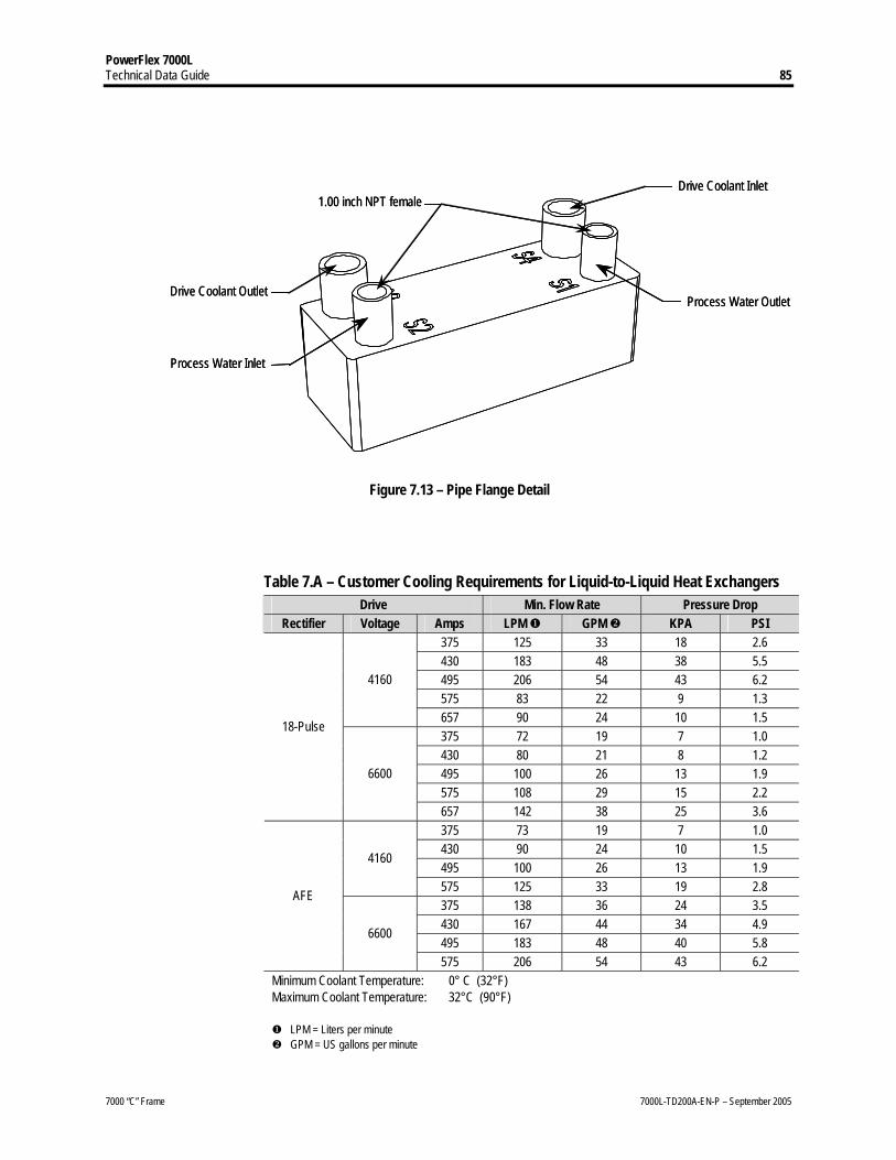
1.00 inch NPT female
Process Water Inlet
Process Water Outlet
Drive Coolant Inlet
Drive Coolant Outlet
1.00 inch NPT female
Process Water Inlet
Process Water Outlet
Drive Coolant Inlet
Drive Coolant Outlet
Figure 7.13 – Pipe Flange Detail Table 7.A – Customer Cooling Requirements for Liquid-to-Liquid Heat Exchangers
Drive Min. Flow Rate Pressure Drop Rectifier Voltage Amps LPM GPM KPA PSI
375 125 33 18 2.6 430 183 48 38 5.5 495 206 54 43 6.2 575 83 22 9 1.3
4160
657 90 24 10 1.5 375 72 19 7 1.0 430 80 21 8 1.2 495 100 26 13 1.9 575 108 29 15 2.2
18-Pulse
6600
657 142 38 25 3.6 375 73 19 7 1.0 430 90 24 10 1.5 495 100 26 13 1.9
4160
575 125 33 19 2.8 375 138 36 24 3.5 430 167 44 34 4.9 495 183 48 40 5.8
AFE
6600
575 206 54 43 6.2 Minimum Coolant Temperature: 0° C (32°F) Maximum Coolant Temperature: 32°C (90°F)
LPM = Liters per minute GPM = US gallons per minute

PowerFlex 7000L 86 Technical Data Guide
7000 “C” Frame 7000L-TD200A-EN-P – September 2005
PowerFlex 7000L service features: • De-ionizing cartridge and fluid strainers are exchangeable during
VFD operation.
• Coolant reservoir replenishable during operation
• Heat exchanger cooling fans and VFD cooling pumps are serviceable during operation.
• Integral cooling system filling pump
• Pumping system factory tested with a dedicated heat exchanger before shipment
• Heat exchanger is factory tested at sub-supplier facility
• Qty (4) x 45-gallon barrels of de-ionized water supplied for initial fill

PowerFlex 7000L Technical Data Guide 87
7000 “C” Frame 7000L-TD200A-EN-P – September 2005
7.5 Specifications Description NEMA IEC
Power Rating (Liquid Cooled) 3000-9000 hp 2240-6715 kW Motor Type Induction or Synchronous Input Voltage Rating 3300V , 4160V, 6600V, 6900V Input Voltage Tolerance ± 10% of Nominal Voltage Sag -30%
Power Loss Ride-Through 5 Cycles (Std) > 5 Cycles (Optional UPS)
Input Protection Metal Oxide Varistor (MOV) Input Frequency 50/60 Hz, +/- 5% Input Short-circuit Current Withstand 5 Cycle 3300 V – 6000 V 25 MVA RMS SYM Basic Impulse Level 50 kV (0 – 1000 m) Power Bus Design Copper – Tin plated Ground Bus Copper – Tin plated 6 x 51 mm (¼ x 2 in.) Customer Control Wire Way Separate and Isolated
Input Power Circuit Protection Vacuum Contactor with Fused Isolating Switch
or Circuit Breaker
Input Impedance Device Isolation Transformer or AC Line Reactor
Output Voltage 0 – 3300 V 0 – 4160 V 0 – 6600 V 0 – 6900 V
Inverter Design PWM Inverter Switch Symmetrical Gate Commutated Thyristor (SGCT) Inverter Switch Failure Mode Non-rupture, Non-arc Inverter Switch Failure Rate (FIT) 100 per 1 Billion Hours Operation Inverter Switch Cooling Double Sided, Low Thermal Stress Inverter Switching Frequency 420-540 Hz
Voltage SGCTs (per phase) Number of Inverter SGCTs 3300/4160 V
6600/6900 V 4 6
Voltage PIV SGCT PIV Rating (Peak Inverse Voltage) 3300/4160 V
6600/6900 V 6500 V 6500 V
Rectifier Designs 18-pulse PWM (Active Front End)
Rectifier Switch SCR (18-pulse), SGCT (PWM Rectifier) Rectifier Switch Failure Mode Non-rupture, Non-arc Rectifier Switch Failure Rate (FIT) 100 per 1 Billion Hours Operation Rectifier Switch Cooling Double Sided, Low Thermal Stress
Voltage 18-Pulse PWM Number of Rectifier Devices per phase 3300 V
4160 V 6600 V
6 6 6
4 4 6
Voltage 18-Pulse PWM SCR PIV Rating (Peak Inverse Voltage)
3300 V 4160 V 6600 V
4500 V 4500 V 6500 V
6500 V 6500 V 6500 V
Output Waveform to Motor Sinusoidal Current / Voltage Medium Voltage Isolation Fiber Optic
Modulation techniques SHE (Selective Harmonic Elimination) PWM (Pulse Width Modulation)
For 3300V designs, contact factory. Short-circuit fault rating based on input protection device (contactor or circuit breaker) BIL derating based on altitudes < 1000 m (3,300 ft.) Refer to factory for derating.

PowerFlex 7000L 88 Technical Data Guide
7000 “C” Frame 7000L-TD200A-EN-P – September 2005
7.5 Specifications (cont.)
Description NEMA IEC
Control Method Digital Sensorless Direct Vector Full Vector Control with Tach Feedback (Optional)
Tuning Method Auto Tuning via Setup Wizard Speed Regulator Bandwidth 5-25 Radians / Second Torque Regulator Bandwidth 15-50 Radians / Second
Speed Regulation 0.1% without Tachometer Feedback 0.01 – 0.02% with Tachometer Feedback
Acceleration/Deceleration Range Independent Accel/Decel – 4 x 30 sec. Acceleration/Deceleration Ramp Rates 4 x Independent Accel/Decel S Ramp Rate Independent Accel/Decel – 2 x 999 sec. Critical Speed Avoidance 3 x Independent with Adjustable bandwidth Stall Protection Delay / Speed Load Loss Detection Adjustable level, delay, speed set points Control Mode Speed or Torque Current Limit Adjustable in Motoring and Regenerative Output Frequency Range 0.2-75 Hz
Normal Duty Heavy Duty Service Duty Rating 110% Overload for 1 minute
every 10 minutes (Variable Torque Load)
Contact Factory
Typical VFD Efficiency > 98% (18-pulse) > 97.5% (PWM)
Contact Factory for Guaranteed Efficiency of Specific Drive Rating
PWM Rectifier 18-Pulse Rectifier with PFCC Input Power Factor 0.98 Minimum,
30-100% Load 0.90-0.95,
12.5-100% Load Meet IEEE 519 Harmonic Guidelines? Yes VFD Noise Level < 85 dB(A) per OSHA Standard 3074 Regenerative Braking Capability Inherent – No Additional Hardware or Software Required
Flying Start Capability Yes – Able to Start into and Control a Spinning Load in Forward or Reverse Direction
Operator Interface 40-character, 16-line formatted text 0.1 Hz Display speed resolution
Languages English Russian Spanish Chinese French
Control Power 208-575 V, 3 Phase, 50/60 Hz External I/O 16 Digital Inputs, 16 Digital Outputs
External Input Ratings 50-60 Hz AC or DC 120-240 V – 1 mA
External Output Ratings 50-60 Hz AC or DC 30-260 V – 1 Amp
Analog Inputs (1) Isolated, (1) Non-isolated, 4-20 mA or 0-10 V
Analog Resolution • Analog input 12 Bit (4-20 mA) • Internal parameter 32 Bit resolution • Serial Communication 16 Bit resolution ( .1 Hz) (Digital Speed Reference)
Analog Outputs (1) Isolated, (7) Non-isolated, 4-20 mA or 0-10 V Communication Interface SCANport /DPI
Scan Time Internal SCANport – 10 ms Internal DPI – 5 ms

PowerFlex 7000L Technical Data Guide 89
7000 “C” Frame 7000L-TD200A-EN-P – September 2005
Description NEMA IEC
Communication Protocol
RIO Interbus DeviceNet Lonworks Control Net Can Open Ethernet RS485 HVAC Profibus RS485 DF1 Modbus RS232 DF1 Modbus + RS232 C
Enclosure NEMA 1/ 12 Force Vent IEC IP21 / IP42
Lifting Device Standard / Removable Mounting Arrangement Mounting Sill Channels
Structure Finish
Epoxy Powder – Paint Exterior Sandtex Light Grey (RAL 7038) – Black (RAL
8022) Internal – Control Sub Plates – High Gloss White (RAL
9003) Interlocking Key provision for customer input Disconnecting Device Corrosion Protection Unpainted Parts (Zinc Plates / Bronze Chromate) Door Filter Painted Diffuser with Matted Filter Media
Coolant Iron and chloride free ethylene glycol mixed with de-ionized water
Coolant Conductivity 1-2 micro-Siemens/CM (Warning/Trip) Heat Exchanger Types Liquid to Air / Liquid to Liquid
Maximum Elevation Lower than internal reservoir Heat Exchanger Installation Maximum Distance
from VFD 12 meters / 40 feet
Heat Exchanger Fan Control Starters / Overload Protection Cooling System Non-pressurized – Closed Loop Cooling Reservoir 41 liters / 11 gallons (U.S.) Cooling Level Protection Level Warning/Trip Cooling Capacity 170 liters / 45 gallons (U.S.) Filling Pump Included – Integral to VFD Cooling Pumps 2 units – Main/Redundant provided with shut-off valves Operating Pressure 50 psi (344 Kpa) Pump Drip Tray Provided for spill containment Pump Control Automatic Cycle – Main/Redundant Pressure Loss Auto Detect / Shutdown Overtemperature Warning / Trip Ambient Temperature 0° to 40°C (32°F to 104°F) Storage and Transportation Temperature Range -40°C to 70°C (-40°F to 185°F)
Relative Humidity 95% Non-Condensing Altitude (Standard) 0 to 3300 ft. (0 to 1000 m) Altitude (Optional) 0 to 16400 ft. (1001 to 5000 m) Seismic (UBC Rating) 1, 2, 3, 4 Standards NEMA, IEC, CSA, UL, ANSI, IEEE

PowerFlex 7000L 90 Technical Data Guide
7000 “C” Frame 7000L-TD200A-EN-P – September 2005
7.6 Typical Auxiliary Equipment
Bulletin No. Description 1508T Isolation Transformer Unit 1512AD 1-High, VFD Input Contactor Unit
1512DM VFD Input Contactor Unit with Output Isolator for Output or Bypass, Single or Multi-Motor Applications
1512DO VFD Output Contactor Unit 1512M Output-Bypass Starter Unit
Bulletin 1508T - Isolation Transformer Unit The isolation transformer is defined by Bulletin number 1508T. It is purchased from a 3rd party
and normally shipped from the supplier directly to the job site. It is available in a variety of enclosure types, sizes, winding materials and voltages.
For variable torque applications, transformers will be sized 1.0 kVA / Motor hp X Drive Service
Factor. Applications at altitudes greater than 1000 meters, will be treated as custom designs.
Bulletin 1512AD, 1512BD - VFD Input Contactor Unit The input contactor is defined by Bulletin numbers 1512AD and 1512BD. The unit is FVNR
available in 400 size. The unit is available in 1-High and 2-High configurations. The input contactor is controlled by the drive. There are several options available with this type of unit that effect the configuration of the structures and wiring of the system. When the load is the isolation transformer, the power fuses will be “E” rated, and “R” rated when “E” rated are NOT available.
Typical Bulletin 1512AD, MV Drive Input Starter Feeding Isolation Transformer
LV
MV
400 amp
Structure Code: 1.2 Catalog No: 1512AD-AA_-6-14TX-kVA Dimensions: 26”W x 36”D x 91”H
VFD
1512ADBD
M

PowerFlex 7000L Technical Data Guide 91
7000 “C” Frame 7000L-TD200A-EN-P – September 2005
Bulletin 1512DM - VFD Input Contactor Unit with Output Isolator for OUTPUT or BYPASS,
Single or Multi-Motor Applications The input contactor unit is a FVNR starter with an output isolating switch on the output of the
VFD that will feed a VFD power bus. The output isolator and FVNR starter isolating switches are mechanically interlocked for the 400 amp design. The OUTPUT or BYPASS configurations are available as standard. The same options used on the 1512AD (above) are available with this unit. This unit shall also include a 500 VA CPT as standard (like a starter application), to supply the control circuit power only for the starter. The catalog number will also included a hp (-14LR) or kVA (-14TX) rating. When the load is the isolation transformer, the power fuses will be “E” rated, and “R” rated when “E” rated are NOT available. When the load is a line reactor, the power fuses will be “R” rated.
NOTE: For any OUTPUT or BYPASS configuration, Allen-Bradley prefers to supply the Input
Contactor. This is to ensure that there is proper isolation and protection (interlocking). A double power bus configuration is utilized in the bus compartment (one is the main power bus,
the other is the variable frequency bus). The variable frequency bus is located above the standard main horizontal power bus.
NOTE: When this unit is located on the left most side of the MCC, only bottom incoming cables can
be terminated to the main horizontal power bus. For top incoming direction, an incoming line unit is required.
Typical Bulletin 1512DM, MV Drive Input Starter ( For use with Output - Bypass Starter)
LV MV
MVOutput
Contactor
InputContactor
400 amp
Structure Code: 1.40 Catalog No: 1512DM-AA_-6-14TX-kVA Dimensions: 36”W x 36”D x 91”H
VFD
VFD Bus
3
1512DM1512M
Bypass
Output
3
M

PowerFlex 7000L 92 Technical Data Guide
7000 “C” Frame 7000L-TD200A-EN-P – September 2005
7.6 Typical Auxiliary Equipment (cont.) Bulletin 1512M - Output-Bypass Starter Unit The output-bypass starters are allowed in the line-up when the 1512DM unit is used. The unit
can be used for both single or multi-motor applications. The catalog number includes a horsepower rating and option numbers. When used in a drive system configuration, the 1512M units shall always be located on the left hand side of the input starter (1512DM). A double power bus configuration is utilized in the bus compartment (one is the main power bus, the other is the variable frequency bus). The variable frequency bus is located above the standard main horizontal power bus. This unit shall include a 500 VA CPT as standard (like a starter application), to supply the control circuit power only for the starter. The power fuses will be “R”.
NOTE: When this unit is located on the left most side of the MCC, only bottom incoming
cables can be terminated to the main horizontal power bus. For top incoming direction, an incoming line unit is required.
Typical Bulletin 1512M, Output-Bypass Starters
LV MV
MVOutputStarter
Bypass Starter
LV
LV MV
MVOutputStarter
Bypass Starter
LV
400 amp
Structure Code: 1.15 Catalog No: 1512M-AA_-6-7F-hp Dimensions: 36”W x 36”D x 91”H
VFD Bus
1512M
Bypass
Output
3
M
400A
Main Bus

PowerFlex 7000L Technical Data Guide 93
7000 “C” Frame 7000L-TD200A-EN-P – September 2005
Bulletin 1512DO - Output Contactor Unit The Bulletin 1512DO is an output contactor for the drive and is allowed in the line-up when a
1512DM unit is used. This unit includes an isolating switch and contactor only. The catalog number includes a horsepower rating and option numbers. When used in a drive system configuration, the 1512DO unit shall always be located on the left hand side of the input starter (1512DM). A double power bus configuration is utilized in the bus compartment (one is the main power bus, the other is the variable frequency bus). The variable frequency bus is located above the standard main horizontal power bus. This unit does not include CPT for the control circuit power. An external power source is required. This unit also does not include power fuses or CTs and is controlled by the drive control circuit. If additional relays, CTs, etc., are required, they shall be included by using CMODs.
Typical Bulletin 1512DO, VFD Output Contactor
LV
MV
MVOutput
Contactor
400 amp
Structure Code: 1.17 Catalog No: 1512DO-AA_-6-7F-HP Dimensions: 36”W x 36”D x 91”H
VFD
VFD Bus
3
1512DM1512DO
Output
M
1:1

PowerFlex 7000L 94 Technical Data Guide
7000 “C” Frame 7000L-TD200A-EN-P – September 2005
8.0 APPENDIX A
Full Load Currents of 3-phase, 50/60 Hz, Medium Voltage AC Induction Motors
This table is FOR REFERENCE ONLY. The full load currents listed below are “average
values” for horsepower rated motors. These “average values,” along with the similar values listed in NEC/CEC, should be used only as a guide for selecting appropriate components for the Motor Branch Circuit. The rated full load current, shown on the motor nameplate, may vary considerably from the list value depending on the specific motor design and RPM.
IMPORTANT: The motor nameplate full load current should always be used in determining the
rating of the devices used for Motor Running Overcurrent Protection.
Full Load Current at 1800 RPM (Amperes) kW Rating
hp Rating 2300V 3300V 4000V 4600V 6000V 6300V 6600V 6900V
75 100 23 16 13 11 9 8 8 8 95 125 29 20 16 14 11 10 10 10 110 150 34 24 20 17 13 13 12 11 130 175 40 28 23 20 15 15 14 13 150 200 46 32 26 23 18 17 16 15 170 225 52 36 30 26 20 19 18 17 187 250 57 40 33 29 22 21 20 19 225 300 68 48 39 34 26 25 24 23 260 350 80 56 46 40 31 29 28 27 300 400 91 64 52 46 35 33 32 30 335 450 103 72 59 51 39 38 36 34 373 500 113 79 65 57 43 41 39 38 450 600 134 94 77 67 52 49 47 45 522 700 158 110 91 79 60 58 55 53 560 750 169 118 97 85 65 62 59 56 600 800 177 124 102 89 68 65 62 59 670 900 202 141 116 101 77 74 70 67 750 1000 216 151 124 108 83 79 75 72 933 1250 273 190 157 137 105 100 95 91
1120 1500 326 227 188 163 125 119 114 109 1300 1750 376 262 216 188 144 137 131 125 1500 2000 434 303 250 217 166 159 151 145 1680 2250 485 338 279 242 186 177 169 162 1865 2500 537 375 309 269 206 196 187 179 2050 2750 591 412 340 296 227 216 206 197 2240 3000 647 451 372 324 248 236 226 216 2600 3500 750 523 431 375 288 274 261 250 3000 4000 857 597 493 429 329 313 299 286 3360 4500 964 672 554 482 370 352 336 321 3730 5000 1071 747 616 536 411 391 373 357 4100 5500 1179 821 678 589 452 430 411 393 4475 6000 1286 896 739 643 493 469 448 429 5225 7000 1500 1046 863 750 575 548 523 500 6000 8000 1714 1195 986 857 657 626 597 571 6720 9000 1929 1344 1109 964 739 704 672 643 7500 10000 2143 1494 1232 1071 821 782 747 714

PowerFlex 7000L Technical Data Guide 95
7000 “C” Frame 7000L-TD200A-EN-P – September 2005
9.0 APPENDIX B
9.1 Transformer Secondary Winding Insulation Levels Table
Primary Winding Impulse Withstand Voltage (BIL) Test (for 1:1 ratio only)
(kVpk)
Secondary Winding Impulse
Withstand Voltage (BIL) Test
(kVpk)
Rated Motor L-L Voltage
(Vrms)
Number of Secondary Windings
Rated Secondary L-L Voltage
(Vrms)
Minimum Secondary
Winding Insulation Level
(kVrms)
Short Duration Power
Frequency Withstand
Voltage Test (kVrms) Air Liquid Air Liquid
2300 1 (6 Pulse/PWM) 2400 5.0 12.0 30 60 30 60 3300 1 (6 Pulse/PWM) 3450 7.2 16.5 40 60 40 60 4000 1 (6 Pulse/PWM) 4200 7.2 16.5 45 75 45 75 6000 1 (6 Pulse/PWM) 6300 12.0 26.0 60 95 60 95 6300 1 (6 Pulse/PWM) 6600 12.0 26.0 60 95 60 95 6600 1 (6 Pulse/PWM) 6900 12.0 26.0 60 95 60 95
Refer to rectifier duty transformer specification 80001-005. Minimum required insulation level from phase-to-ground, neutral-to-ground transformers. Contact factory for 6900V data.

PowerFlex 7000L 96 Technical Data Guide
7000 “C” Frame 7000L-TD200A-EN-P – September 2005
10. APPENDIX C: Applicable Requirements of MV Controllers 10.1 Critical Standards
Code Governing Association/Description CEC-1998 Canadian Electrical Code- SAFETY STANDARD FOR ELECTRICAL INSTALLATIONS NEC-1999 NATIONAL ELECTRICAL CODE (NFPA-70) CSA C22.2 INDUSTRIAL CONTROL EQUIPMENT (MV) No.14/73 TIL NO D-21 CERTIFICATION REQUIREMENTS FOR CONTROL DEVICES RATED AT MORE THAN 1500V BUT
NO MORE THAN 7200V FOR ELECTRIC MOTORS UL347 HIGH VOLTAGE INDUSTRIAL CONTROL EQUIPMENT IEEE –C37 CIRCUIT BREAKERS, SWITCHGEAR, SUBSTATIONS, AND FUSE STANDARDS COLLECTION NEMA-ICS1 GENERAL STANDARD FOR INDUSTRIAL CONTROL SYSTEM NEMA-ICS3 FACTORY BUILT ASSMBLIES NEMA-ICS6 ENCLOSURES IEC 60129 ALTERNATING CURRENT DISCONNECTORS (ISOLATORS) AND EARTHING SWITCHES IEC 60298 AC METAL-ENCLOSED SWITCHGEAR AND CONTROLGEAR FOR RATED VOLTAGE ABOVE 1KV
AND UP TO INCLUDING 52KV IEC 60470 HIGH-VOLTAGE ALTERNATING CURRENT CONTACTORS IEC 60694 COMMON SPECIFICATIONS FOR HIGH-VOLTAGE SWITCHGEAR AND CONTROLGEAR
STANDARDS 89/336/EEC, AND 92/31/EEC ASSOCIATED EN STANDARDS: EN 5081-2, EN 5082-2
EMC DIRECTIVE
92/59/EEC AND ASSOCIATED EN STANDARDS: EN 6010, EN60204-1.
GENERAL PRODUCT SAFETY DIRECTIVE (GPSD)
10.2 Component Standards
Code Description C22.2 No.14/95 INDUSTRIAL CONTROL EQUIPMENT (LV) C22.2 No. 58 HIGH-VOLTAGE ISOLATING SWITCHES C22.2 No. 201 METAL-ENCLOSED HIGH VOLTAGE BUSSWAYS C22.2 No. 127 HIGH-VOLTAGE ISOLATING SWITCHES C22.2 No. 190 CAPACITORS FOR POWER FACTOR CORRECTION C22.2 No. 193 HIGH VOLTAGE FULL LOAD INTERRUPTER SWITCHES UL508 INDUSTRIAL CONTROL EQUIPMENT (LV) UL 1072 MEDIUM, VOLTAGE POWER CABLES UL 1562 TRANSFORMERS, DISTRIBUTION, DRY TYPE OVER 600V NEMA-MG1 MOTOR AND GENERATORS IEC 60056 HIGH-VOLTAGE ALTERNATING-CURRENT CIRCUIT-BREAKERS IEC 60076 POWER TRANSFORMERS IEC 60265-1 HIGH-VOLTAGE SWITCHES - PART 1: HIGH-VOLTAGE SWITCHES FOR RATED VOLTAGES
ABOVE 1 kV AND LESS THAN 52 kV IEC 60420 HIGH-VOLTAGE ALTERNATING CURRENT SWITCH-FUSE COMBINATIONS IEC 60282-1 HIGH-VOLTAGE FUSES IEC 60871-1 SHUNT CAPACITORS FOR A.C. POWER SYSTEMS HAVING A RATED VOLTAGE ABOVE 1000 V


www.rockwellautomation.com Corporate Headquarters Rockwell Automation, 777 East Wisconsin Avenue, Suite 1400, Milwaukee, WI, 53202-5302 USA, Tel: (1) 414.212.5200, Fax: (1) 414.212.5201 Headquarters for Allen-Bradley Products, Rockwell Software Products and Global Manufacturing Solutions Americas: Rockwell Automation, 1201 South Second Street, Milwaukee, WI 53204-2496 USA, Tel: (1) 414.382.2000, Fax: (1) 414.382.4444 Europe/Middle East/Africa: Rockwell Automation SA/NV, Vorstlaan/Boulevard du Souverain 36, 1170 Brussels, Belgium, Tel: (32) 2 663 0600, Fax: (32) 2 663 0640 Asia Pacific: Rockwell Automation, Level 14, Core F, Cyberport 3, 100 Cyberport Road, Hong Kong, Tel: (852) 2887 4788, Fax: (852) 2508 1846 Headquarters for Dodge and Reliance Electric Products Americas: Rockwell Automation, 6040 Ponders Court, Greenville, SC 29615-4617 USA, Tel: (1) 864.297.4800, Fax: (1) 864.281.2433 Europe/Middle East/Africa: Rockwell Automation, Herman-Heinrich-Gossen-Strasse 3, 50858 Köln, Germany, Tel: 49 (0) 2234 379410, Fax: 49 (0) 2234 3794164 Asia Pacific: Rockwell Automation, 55 Newton Road, #11-01/02 Revenue House, Singapore 307987, Tel: (65) 6356 9077, Fax: (65) 6356 9011 Medium Voltage Products, 135 Dundas Street, Cambridge, ON, N1R 5X1 Canada, Tel: (1) 519.740.4100, Fax: (1) 519.623.8930, www.ab.com/mvb Publication 7000L-TD200A-EN-P – September 2005 Copyright © 2005 Rockwell Automation, Inc. All rights reserved. Printed in Canada.