medical photonics lecture 1.2 optical engineeringengineering... · reflection mirrors beam...
TRANSCRIPT

www.iap.uni-jena.de
Medical Photonics Lecture 1.2
Optical Engineering
Lecture 4: Components
2017-11-16
Michael Kempe
Winter term 2017
2
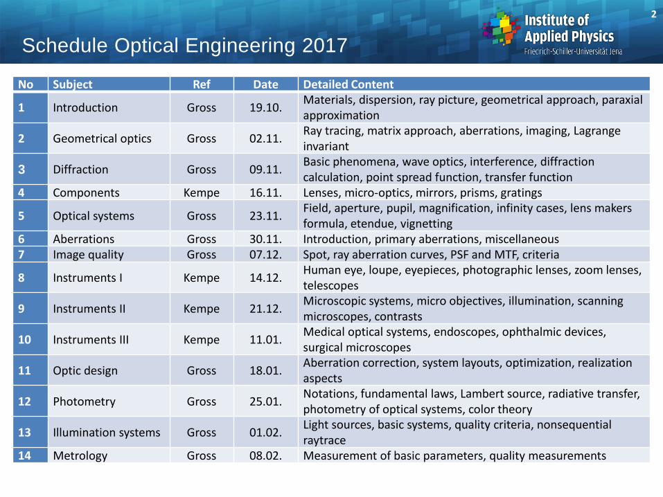
Schedule Optical Engineering 2017
No Subject Ref Date Detailed Content
1 Introduction Gross 19.10. Materials, dispersion, ray picture, geometrical approach, paraxial approximation
2 Geometrical optics Gross 02.11. Ray tracing, matrix approach, aberrations, imaging, Lagrange invariant
3 Diffraction Gross 09.11. Basic phenomena, wave optics, interference, diffraction calculation, point spread function, transfer function
4 Components Kempe 16.11. Lenses, micro-optics, mirrors, prisms, gratings
5 Optical systems Gross 23.11. Field, aperture, pupil, magnification, infinity cases, lens makers formula, etendue, vignetting
6 Aberrations Gross 30.11. Introduction, primary aberrations, miscellaneous 7 Image quality Gross 07.12. Spot, ray aberration curves, PSF and MTF, criteria
8 Instruments I Kempe 14.12. Human eye, loupe, eyepieces, photographic lenses, zoom lenses, telescopes
9 Instruments II Kempe 21.12. Microscopic systems, micro objectives, illumination, scanning microscopes, contrasts
10 Instruments III Kempe 11.01. Medical optical systems, endoscopes, ophthalmic devices, surgical microscopes
11 Optic design Gross 18.01. Aberration correction, system layouts, optimization, realization aspects
12 Photometry Gross 25.01. Notations, fundamental laws, Lambert source, radiative transfer, photometry of optical systems, color theory
13 Illumination systems Gross 01.02. Light sources, basic systems, quality criteria, nonsequential raytrace
14 Metrology Gross 08.02. Measurement of basic parameters, quality measurements

Lenses are key elements in optical systems for
• Optical imaging
• Optical projection
• Light beam shaping, e.g. focusing (energy concentration)
Lenses in Optical Systems
3
from infinity
real image
virtual image
F F'
F'F
F'F
virtual object
location
Virtuell
F F'
virtual image

Imaging by Lenses
4
Lens equation (paraxial approximation, 𝑛 = 𝑛‘): 1
𝑠′−
1
𝑠=
1
𝑓′= −
1
𝑓
Magnification: 𝑚 =𝑦′
𝑦=
𝑠′
𝑠=
𝑓′−𝑠′
𝑓′
F'F
y
f f
y'
s's
F'F
y
f f
y'
s'
s

5
Cardinal Elements of a Refractive Lens
Focal points:
1. incoming ray parallel to the axis
intersects the axis in F‘
2. ray through F is leaves the lens
parallel to the axis
The focal lengths are referenced
on the principal planes
Nodal points:
Ray through N goes through N‘
and preserves the direction
nodal planes
N N'
u
u'
f '
P' F'
sBFLprincipal
planes
backfocalplane
PF
frontfocalplane
f
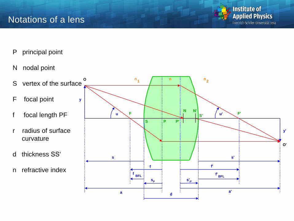
P principal point
N nodal point
S vertex of the surface
F focal point
f focal length PF
r radius of surface
curvature
d thickness SS‘
n refractive index
O
O'
y'
y
F F'
S
S'
P P'
N N'
n n n1 2
f'
a'
f'BFL
fBFL
a
f
s's
d
sP
s'P'
u'u
Notations of a lens

Main notations and properties of a lens:
- radii of curvature r1 , r2
curvatures c
sign: r > 0 : center of curvature
is located on the right side
- thickness d along the axis
- diameter D
- index of refraction of lens material n
Focal length (paraxial)
Optical power
Back focal length
intersection length,
measured from the vertex point
2
2
1
1
11
rc
rc
'tan',
tan
'
u
yf
u
yf F
'
'
f
n
f
nF
'' '' PBFLF sffs
Main properties of a lens

Different shapes of singlet lenses:
1. bi-, symmetric
2. plane convex / concave, one surface plane
3. Meniscus, both surface radii with the same sign
Convex: bending outside
Concave: hollow surface
Principal planes P, P‘: outside for meniscus shaped lenses
P'P
bi-convex lens
P'P
plane-convex lens
P'P
positive
meniscus lens
P P'
bi-concave lens
P'P
plane-concave
lens
P P'
negative
meniscus lens
Lens shape

Spherical Lenses Exhibit Aberrations
• Example: spherical aberration
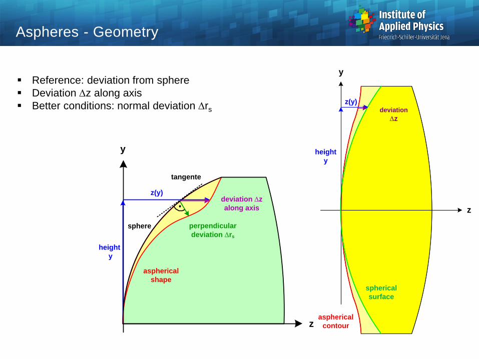
Aspheres - Geometry
z
y
aspherical
contour
spherical
surface
z(y)
height
y
deviation
z
sphere
z
y
perpendicular
deviation rs
deviation z
along axis
height
y
tangente
z(y)
aspherical
shape
Reference: deviation from sphere
Deviation z along axis
Better conditions: normal deviation rs

Reducing the Number of Lenses with Aspheres
Example photographic zoom lens
Equivalent performance
9 lenses reduced to 6 lenses
Overall length reduced
Ref: H. Zügge
436 nm
588 nm
656 nm
xpyp
xy
axis field 22°
xpyp
xy
xpyp
xy
axis field 22°
xpyp
xy
A1A3
A2
a) all spherical, 9 lenses
b) 3 aspheres, 6 lenses,
shorter, better performance
Photographic lens f = 53 mm , F# = 6.5
∆𝑥
∆𝑥

Fresnel Lenses
• Fresnel lenses are refractive lenses with a surface structure
• They are used to reduce weight and length of optical systems
• Significant
aberrations used
for illumination
active
surfaces
linear

Diffractive Optical Elements
• Diffractive optical elements (DOE‘s) are based on diffraction to redirect light
• Different types:
Fresnel zone plates (transmission or phase zones)
Binary diffractive elements
Computer generated diffractive elements
Blazed diffractive element
refractive :
one direction
n
diffractive blazed :
one direction
g
g
+1. order
+2. order
-2. order
-1. order
0. order
diffractive binary :
all directions
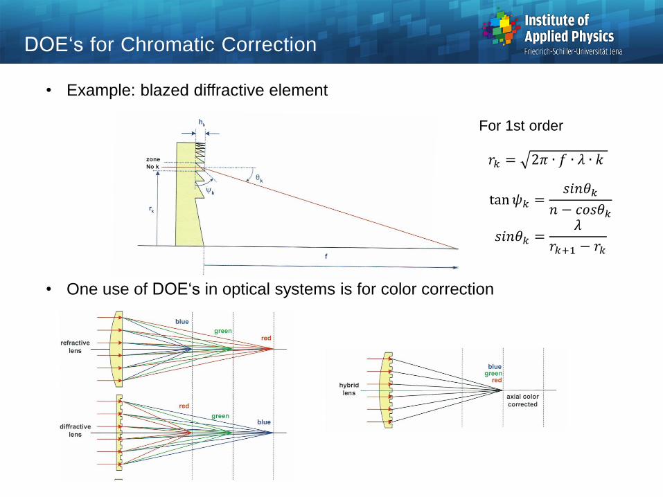
DOE‘s for Chromatic Correction
• Example: blazed diffractive element
• One use of DOE‘s in optical systems is for color correction
P. 676 𝑟𝑘 = 2𝜋 ∙ 𝑓 ∙ 𝜆 ∙ 𝑘
For 1st order
tan𝜓𝑘 =𝑠𝑖𝑛𝜃𝑘
𝑛 − 𝑐𝑜𝑠𝜃𝑘
𝑠𝑖𝑛𝜃𝑘 =𝜆
𝑟𝑘+1 − 𝑟𝑘
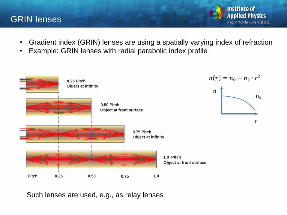
GRIN lenses
• Gradient index (GRIN) lenses are using a spatially varying index of refraction
• Example: GRIN lenses with radial parabolic index profile
𝑛 𝑟 = 𝑛0 − 𝑛2 ∙ 𝑟²
r
n n0
Such lenses are used, e.g., as relay lenses
0.25 Pitch
Object at infinity
0.50 Pitch
Object at front surface
0.75 Pitch
Object at infinity
1.0 Pitch
Object at front surface
Pitch 0.25 0.50 0.75 1.0

Micro Lens Array
Pupil shape quadratic
No dead zones
Ref: W. Osten
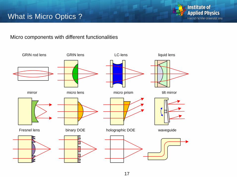
What is Micro Optics ?
17
GRIN rod lens GRIN lens LC-lens liquid lens
mirror micro lens micro prism tilt mirror
Fresnel lens binary DOE holographic DOE waveguide
Micro components with different functionalities

Small dimension: what feature is small ?
One dimension ? All dimensions ?
Fine structure on surface ?
What is Micro-Optic ?
18
x y z
largefine
structuredsmall
x y z LED, photonic crystals
x y z Bragg grating, endoscope
x y z Fiber
x y z Arrays, MEMs, DMDs, DOEs, stacked planar
x y z Linear grating
x y z Coating
x y z Macro optics
6
5
4
3
2
1
No
0
Dimension

Plastic Components of Small Size
Manufacturing of complex geometries in high volumes
Integration of assembly mechanics
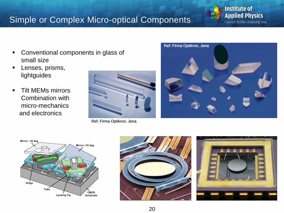
Conventional components in glass of
small size
Lenses, prisms,
lightguides
Tilt MEMs mirrors
Combination with
micro-mechanics
and electronics
Simple or Complex Micro-optical Components
20
Ref: Firma Optikron, Jena
Ref: Firma Optikron, Jena

Mirrors
• Mirrors are based on reflection, typically off coated surfaces (dielectric/metal)
• The reflectivity but not the direction depend on the wavelength and polarization
21
n n'
incidence
reflection transmission
interface
E
B
i
i
E
B
r
r
E
Bt
t
normal to the interface
i
i'i
a) s-polarization
n n'
incidence
reflection
transmission
interface
B
E
i
i
B
E
r
r
B
E t
t
normal to the interface
i'i
i
b) p-polarization
In optical systems mirrors are
used to redirect light and to
control aberrations
Reflectivity of silver

Astigmatism for Curved Spherical Mirrors
22
22
11'
'
131'
'
R
s
R
ys
R
s
R
ys
S
T
Image surfaces for a concave mirror
y‘ : image height
𝑠 : stop position
Special cases of flat image shells as a
function of the stop position
a) stop a center:
zero astigmatism
b) stop at distance
0.42 R:
T=0
c) stop at distance
0.29 R:
B = 0 (best plane)
d) stop at mirror:
S = 0
22
stop
C
RR/2
P B STstop
C
R
0.42 R
P BS T
stop
C
R
P BS T
stop
C
R
P BS T
a) astigmatism A = 0 b) tangential flat
c) best image flat d) sagittal flat
0.29 R

23
Avoiding Mirror Obscuration
Avoiding the central obscuration in mirror systems
Field bias or aperture offset as opportunities
Ref.: K. Fuerschbach

22 yxz
222
22
111 yxc
yxcz
22
22 yxRRRRz xxyy
Conic section
Special case spherical
Cone
Toroidal surface with
radii Rx and Ry in the two
section planes
Generalized conic section without
circular symmetry
Roof surface
2222
22
1111 ycxc
ycxcz
yyxx
yx
z y tan
24
Aspherical Surface Types

222
22
111 yxc
yxcz
1
2
b
a
2a
bc
1
1
cb
1
1
ca
Explicite surface equation, resolved to z
Parameters: curvature c = 1 / R
conic parameter
Influence of on the surface shape
Relations with axis lengths a,b of conic sections
Parameter Surface shape
= - 1 paraboloid
< - 1 hyperboloid
= 0 sphere
> 0 oblate ellipsoid (disc)
0 > > - 1 prolate ellipsoid (cigar )
25
Conic Sections
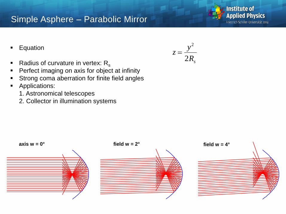
Simple Asphere – Parabolic Mirror
sR
yz
2
2
axis w = 0° field w = 2° field w = 4°
Equation
Radius of curvature in vertex: Rs
Perfect imaging on axis for object at infinity
Strong coma aberration for finite field angles
Applications:
1. Astronomical telescopes
2. Collector in illumination systems

Simple Asphere – Elliptical Mirror
22
2
)1(11 cy
ycz
F
s
s'
F'
Equation
Radius of curvature r in vertex, curvature c
eccentricity
Two different shapes: oblate / prolate
Perfect imaging on axis for finite object and image loaction
Different magnifications depending on
used part of the mirror
Applications:
Illumination systems

Reflection Prisms
Right angle prism
90°deflection
Penta prism
90°deflection
Rhomboid prism
Beam offset
Bauernfeind prism
Beam deviation
Dove prism
image inversion

Properties of Reflection Prisms
Functions
1. Bending of the beam path, deflection of the axial ray direction
Application in instrumental optics and folded ray paths
2. Parallel off-set, lateral displacement of the axial ray
3. Modification of the image orientation with four options:
a. Invariant image orientation
b. Reverted image ( side reversal )
c. Inverted image ( upside down )
d. Complete image inversion (inverted-reverted image)
The number of mirrors is important
Every mirror generates a complete inversion,
No change for even numbers
l/r and u/d separation by roof-edge prisms
4. Off-set of the image position, shift of image position forwards in the propagation direction.
Aberrations introduced
1. Astigmatism
2. Chromatic aberration
3. Spherical aberration in non-collimated beams

Transformation of Image Orientation
Modification of the image orientation
with four options:
1. Invariant image orientation
2. Reverted image ( side reversal )
3. Inverted image ( upside down )
4. Complete image inversion
(inverted-reverted image)
Image side reversal in the
principal plane of one mirror
Inversion for an odd number
of reflections
Special case roof prims:
Corresponds to one reflection
in the edge plane,
Corresponds to two reflections
perpendicular to the edge plane
y
x
y
x
y
x
mirror 1
mirror 2
y - z- folding
plane
z
z
image reversion in the
folding plane
(upside down)
image
unchanged
image
inversion
original
folding planeimage reversion
perpendicular to the
folding plane

Transform of Image Orientation
Rotatable Dove prism:
Azimutal angle: image rotates by the double angle
Application: periscopes
object
Bild
0° 45° 90°angle of prism
rotation
angle of image
rotation 0° 90° 180°

Types of Reflection Prisms: Porro Prism
Porrro Prism
Incoming ray direction inverted in one section
Version with roof-edge:
Ray direction inverted in 3D (retro reflector, cats eye reflector)
roof-edge
D
90°
a
v

Roof-Edge Prism
Roof edge:
- two reflecting surfaces with 90°
- change of lateral coordinate in one section
Critical in practice:
Precision of 90° angle,
typical tolerance 1‘‘
errors cause image split
Coatings critical due to
polarization effects
sA
D
B
C
roof edge
intersection plane
with angle of 90°
intersection
planes with
angles of 2

Application in Binoculars
Double Porro Prism
Abbe-König Roof Prism

Conical Light Taper
Waveguide with conical boundary
Lagrange invariant: decrease in diameter causes increase in angle:
Aperture transformed
Number of reflections:
- depends on diameter/length ratio
- defines change of aperture angle
'sinsin uDuD outin
u'
u
L
Din
/
2
n
Dout
/
2
Reflexion
No j
r i
n

Dispersion Prism
Dispersion prism spatially separate light in its colors
Blue light is refracted more strongly than red light ( normal dispersion)
Application : spectrometer, dispersion control
2sinarcsin2 n
For symmetric case
𝑑𝜑
𝑑𝜆=
2sin 𝛼/2
1 − 𝑛2𝑠𝑖𝑛² 𝛼/2
𝑑𝑛
𝑑𝜆
rot
grün
blau
weiß
red
green
blue
white
𝛼

Ideal diffraction grating:
monochromatic incident collimated
beam is decomposed into
discrete sharp diffraction orders
Constructive interference of the
contributions of all periodic cells
Only two orders for sinusoidal
Ideal Diffraction Grating
grating
g = 1 / s
incidentcollimated
light
grating constant
-1.
-2.
-3.
0.
-4.
+1.
+2.
+3.
+4.
diffraction orders

Grating Diffraction
Maximum intensity:
constructive interference of the contributions
of all periods
Grating equation
g mo sin sin
grating
g
incident
light
+ 1.
diffraction
order
s =
in-phase
grating
constant

Grating Equation
Intensity of grating diffraction pattern
(scalar approximation g >> )
Product of slit-diffraction and
interference function
Maxima of pattern:
coincidence of peaks of both
functions: grating equation
Angle spread of an order decreases
with growing number od periods N
Oblique phase gradient:
- relative shift of both functions
- selection of peaks/order
- basic principle of blazing
2
22
sin
sinsin
ugN
ugN
ug
ug
gNI
mg osinsin
-3 -2 -1 0 1 2 30
0.1
0.2
0.3
0.4
0.5
0.6
0.7
0.8
0.9
1
u = sin

Spectral Resolution of a Grating
Angle dispersion of a grating
Separation of two spectral lines
Complete setup with all orders:
Overlap of spectra possible at higher orders
m
m
d
dD
cos
sinsin 0
NmLA m
0sinsin
0.+1. +2.
+3.
+4.-4.
-3.-2. -1.
0
0.2
0.4
0.6
0.8
1
I(x)
m /g
sin
m( /g

Blaze grating (echelette):
- facets with finite slope
- additional phase shifts the slit diffraction function
- all orders but oen suppressed
Blaze condition is only valid for
- one wavelength
- one incidence angle
Blaze Grating
suppressed ordersworking order
0
0.1
0.2
0.3
0.4
0.5
0.6
0.7
0.8
0.9
1
mB mB+1 mB+2mB-1mB-2
slit diffraction