medical applications of synchrotron radiation: growth … · medical applications of synchrotron...
TRANSCRIPT

Medical Applications of Synchrotron Radiation:Growth and Outlook for an Emerging Field of Science
W. Thomlinson
Frau Roentgen’s Hand
Wilhelm Roentgen’s LaboratoryUniversity of Wurtzburg 1895 European Synchrotron Radiation Facility
Grenoble France, 2010
3D monochromatic high-resolutiondynamic digital imaging ANSTO
Nov. 30, 2010
115 YearsLater

Synchrotron Radiation is Extremely Intense Light!
The Electromagnetic Spectrum
Synchrotron Radiation
Light is produced by the Acceleration of Charged Particles.
In Synchrotron Facilities, these Particles are Electrons
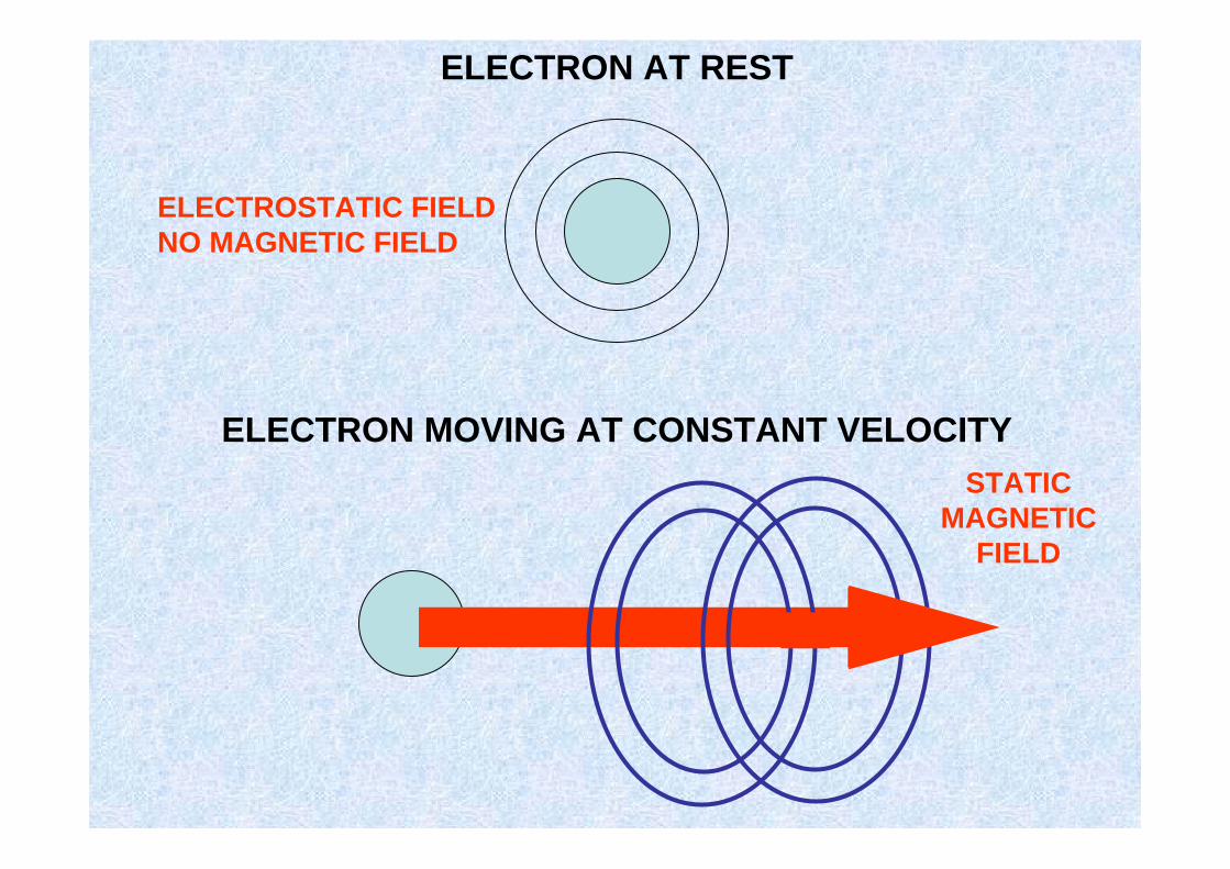
ELECTRON AT REST
ELECTROSTATIC FIELDNO MAGNETIC FIELD
ELECTRON MOVING AT CONSTANT VELOCITYSTATIC
MAGNETICFIELD

ACCELERATING ELECTRON (LINEAR)
SLOW FAST
ELECTROMAGNETIC RADIATION = LIGHT
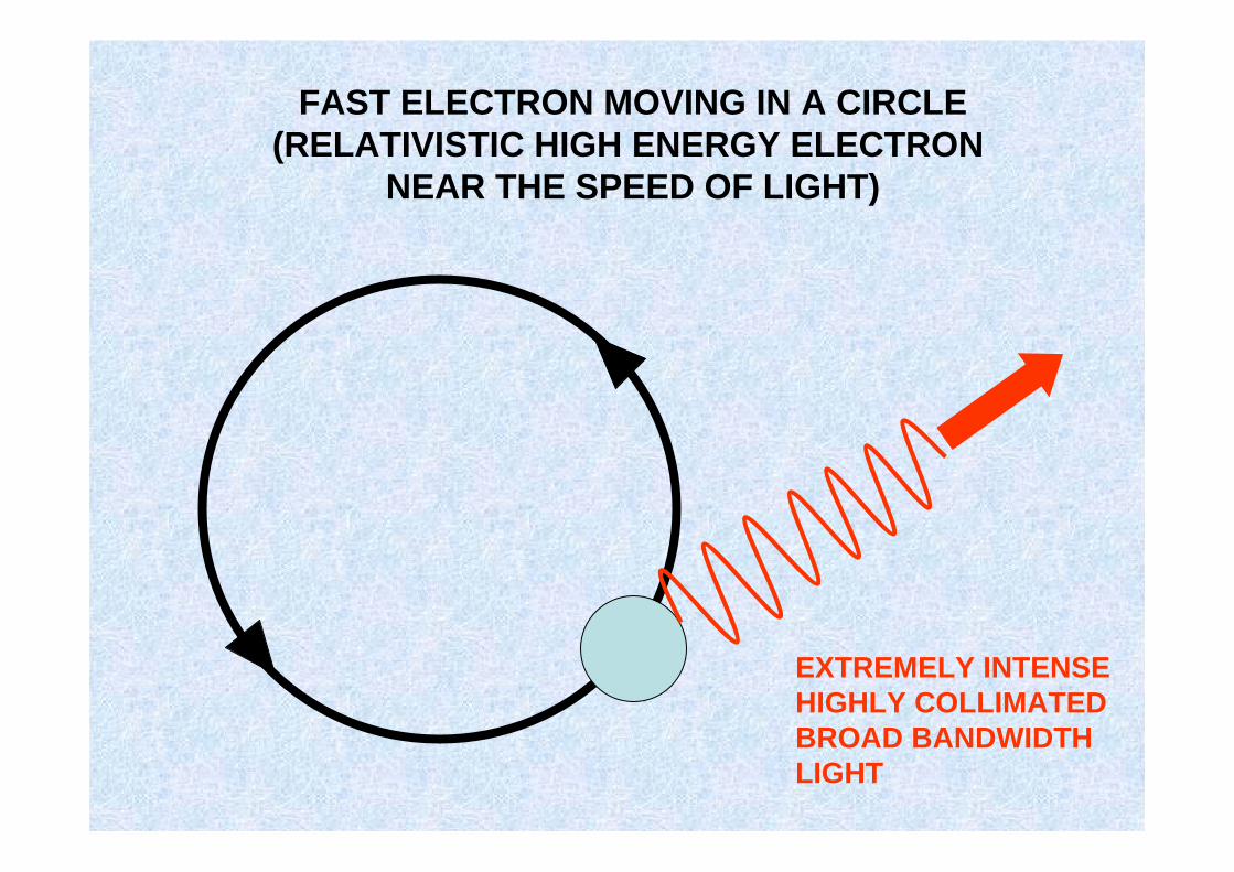
FAST ELECTRON MOVING IN A CIRCLE(RELATIVISTIC HIGH ENERGY ELECTRON
NEAR THE SPEED OF LIGHT)
EXTREMELY INTENSEHIGHLY COLLIMATEDBROAD BANDWIDTHLIGHT
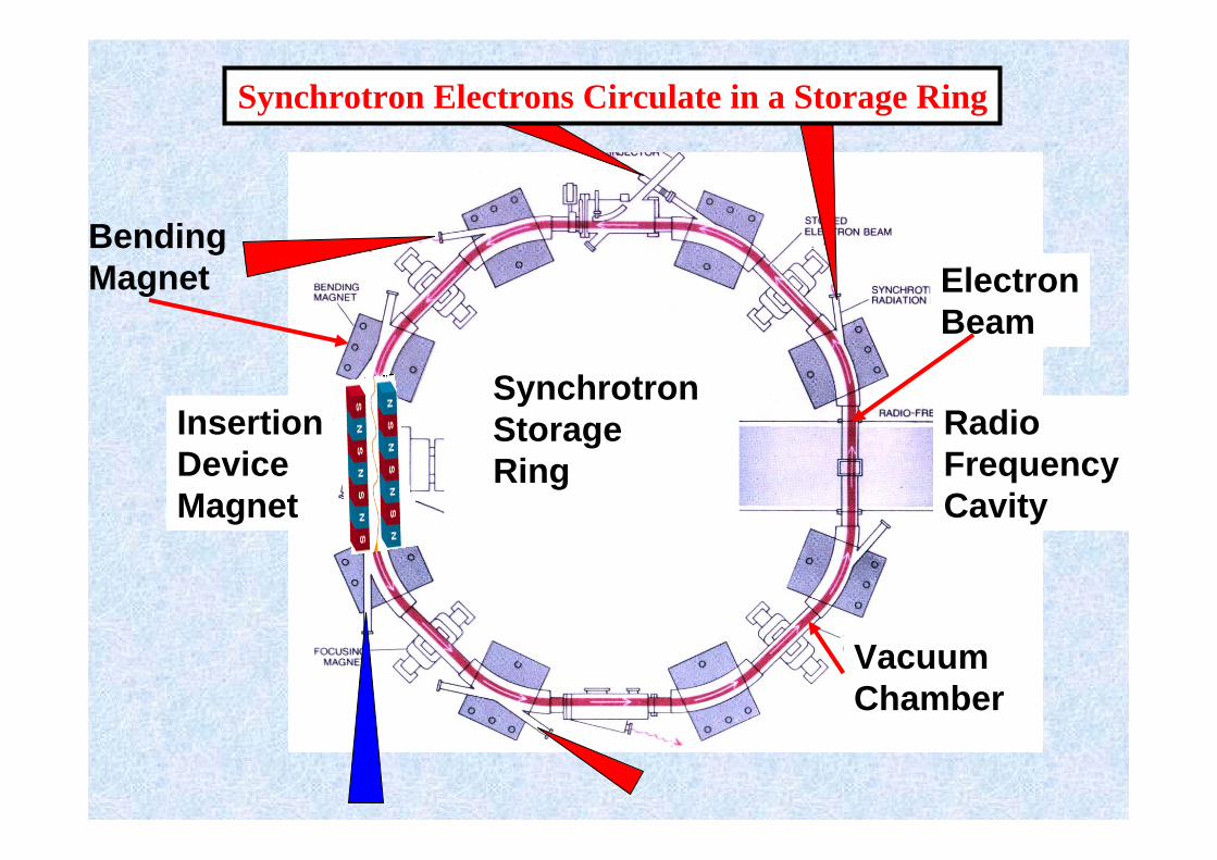
Bending Magnet
InsertionDeviceMagnet
VacuumChamber
ElectronBeam
Synchrotron StorageRing
RadioFrequencyCavity
Synchrotron Electrons Circulate in a Storage Ring

Phot
ons/
s/0.
1%/m
rad
Photon Energy (KeV)
0 10 20 30 40 50 60 70 80 901E+09
1E+10
1E+11
1E+12
1E+13
1E+14
1E+15
XX--Ray tube Ray tube -- 110KV 110KV -- 2.5mm Al @meter/source2.5mm Al @meter/sourceESRF ID 17 @ 200mA ESRF ID 17 @ 200mA -- Wiggler: 1.4T Wiggler: 1.4T -- 1.6m 1.6m -- 150mm150mm
Synchrotron Brightness and Flux
Brightness of the X-ray Beams
ID17 Wiggler
Intense Lab Source
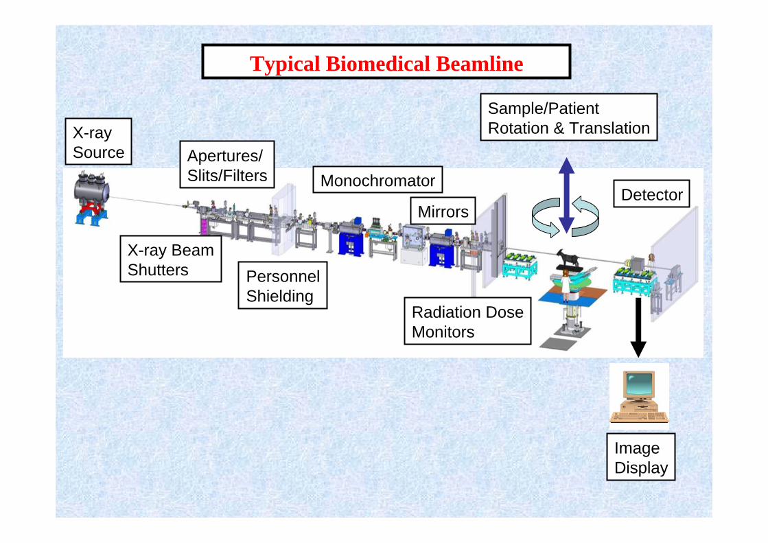
Typical Biomedical Beamline
X-raySource
Radiation DoseMonitors
Mirrors
Apertures/Slits/Filters Monochromator
PersonnelShielding
Sample/PatientRotation & Translation
Detector
X-ray BeamShutters
ImageDisplay

World Wide Synchrotron FacilitiesBiomedical Research Programs – 2010
2nd Generation 3rd Generation Biomedical Beamlines
ESRF
NSLS ELETTRASP-8
SSRF
AS
CLS
PF

The Beginning:Stanford Synchrotron Radiation Lightsource
SLAC
SSRL
Human Coronary Angiography
E. Rubenstein – Stanford MedicalR. Hofstadter – Stanford Physics
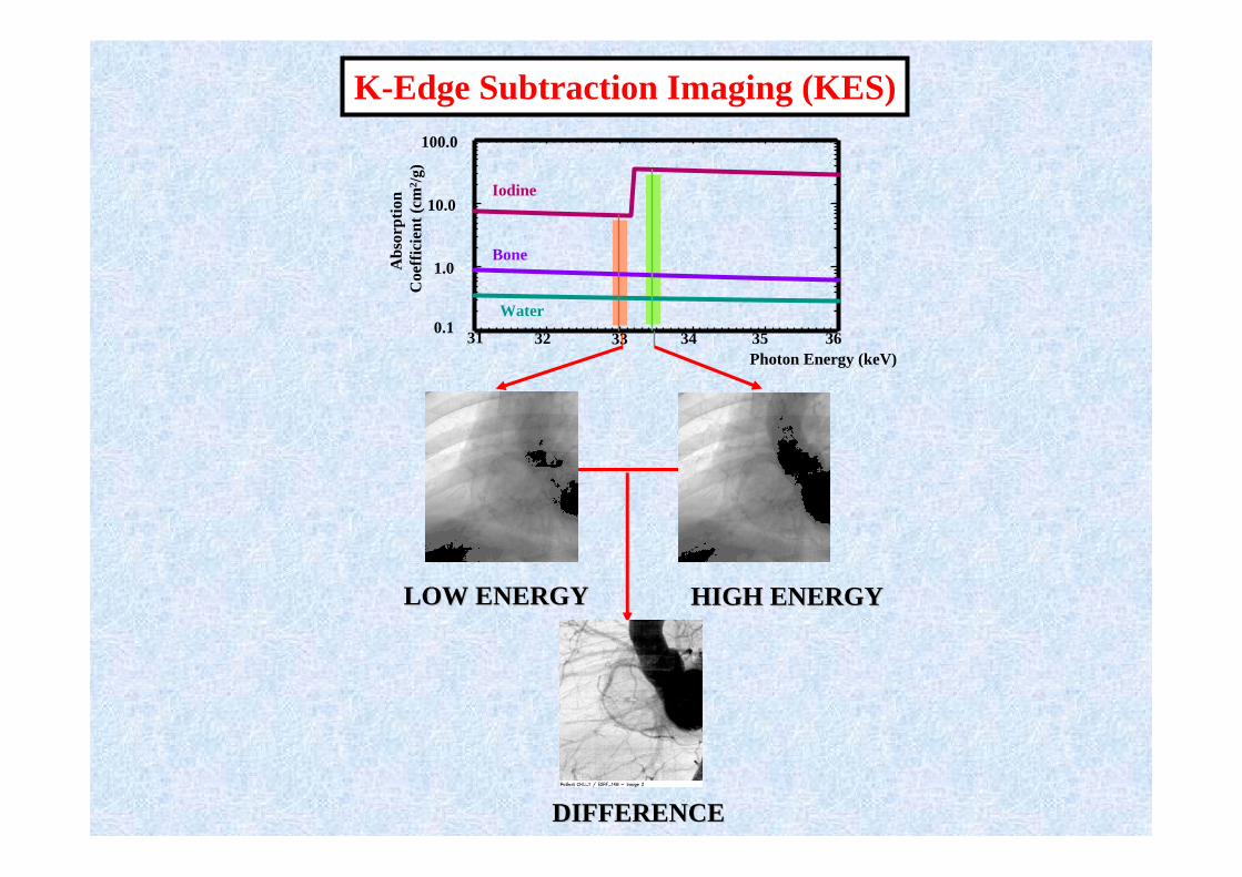
HIGH ENERGYHIGH ENERGYLOW ENERGYLOW ENERGY
DIFFERENCEDIFFERENCE
Photon Energy (keV)
Iodine
Bone
Water
31 32 33 34 35 360.1
1.0
10.0
100.0
Abs
orpt
ion
Coe
ffic
ient
(cm
2 /g)
K-Edge Subtraction Imaging (KES)

Stanford Angiography Beamline
Patient Chair
Angiography Hutch
yAngiography Hutch
PhysicianControl
MonoHutch

Ed Rubenstein,Bob Hofstadter andthe group relaxing at last!
First Images
First Human Angiography Images at SSRL May 22, 1986
Anxious moments…..
Photos courtesyBill Thomlinson
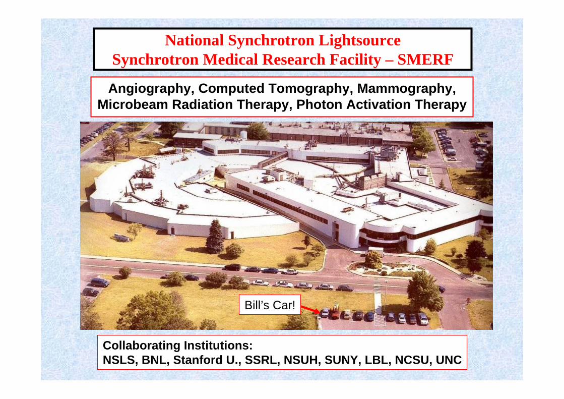
National Synchrotron LightsourceSynchrotron Medical Research Facility – SMERF
Collaborating Institutions:NSLS, BNL, Stanford U., SSRL, NSUH, SUNY, LBL, NCSU, UNC
Angiography, Computed Tomography, Mammography,Microbeam Radiation Therapy, Photon Activation Therapy
Bill’s Car!

NSLS SMERF Angiography Facility
FLUOROSCOPYROOM
RECEPTION ROOM
ANGIOGRAPHY ROOM

First Human Angiography Images at NSLS -- October 5, 1990
E. Rubenstein
J. Giacomini
NSLS/BNL/NSUH/LBLStanford &Palo Alto VA
International Collaboration
USA
Australia
Japan
Germany
FranceFinland
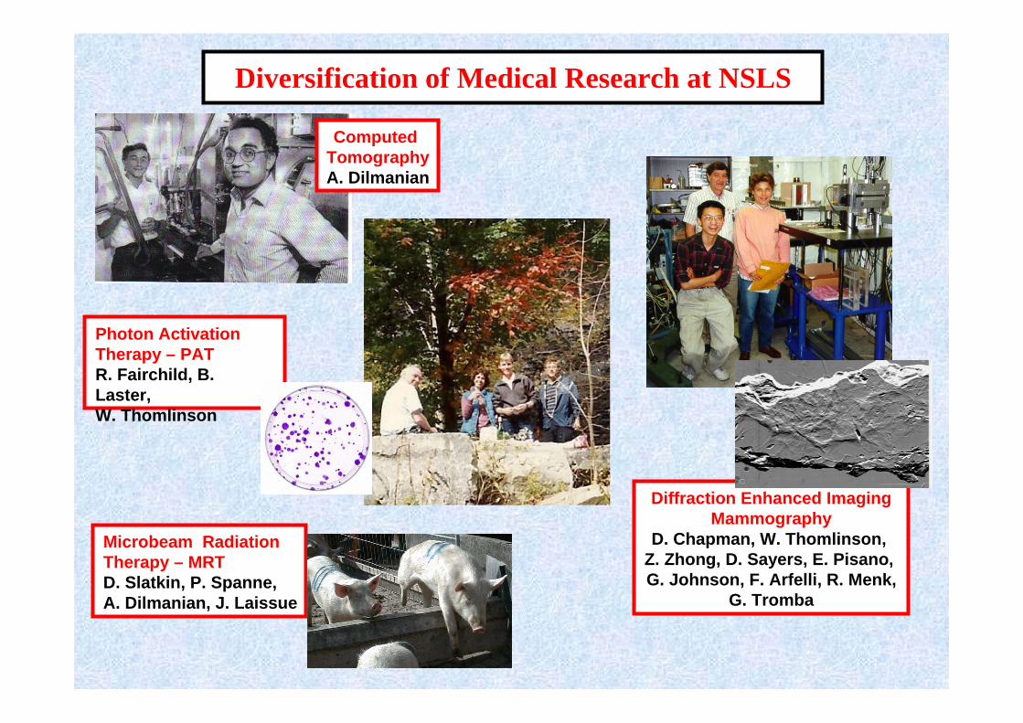
Diversification of Medical Research at NSLS
Diffraction Enhanced ImagingMammography
D. Chapman, W. Thomlinson, Z. Zhong, D. Sayers, E. Pisano, G. Johnson, F. Arfelli, R. Menk,
G. Tromba
Computed TomographyA. Dilmanian
Microbeam Radiation Therapy – MRTD. Slatkin, P. Spanne,A. Dilmanian, J. Laissue
Photon Activation Therapy – PATR. Fairchild, B. Laster,W. Thomlinson
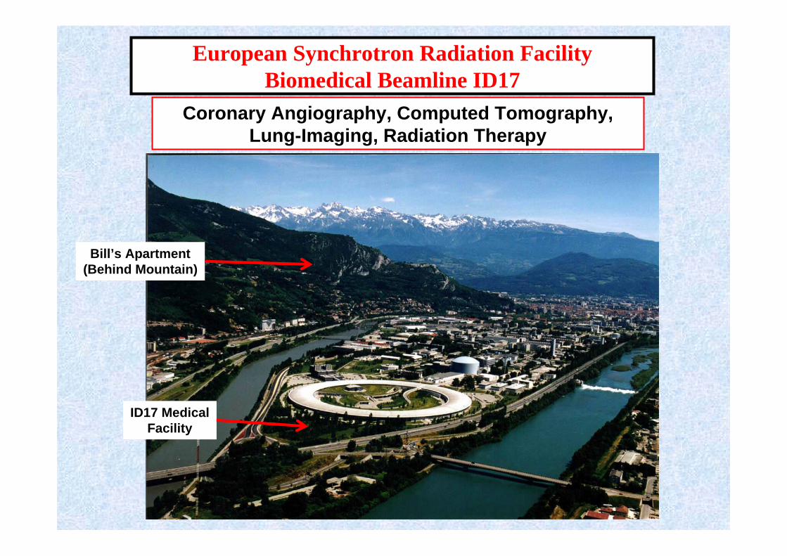
European Synchrotron Radiation FacilityBiomedical Beamline ID17
Coronary Angiography, Computed Tomography, Lung-Imaging, Radiation Therapy
Bill’s Apartment(Behind Mountain)
ID17 MedicalFacility

ESRF Biomedical Beamline ID17
EXPERIMENTAL HUTCH
MONOCHROMATORS
Animalerie Experimental Hall
ESRFStorage Ring
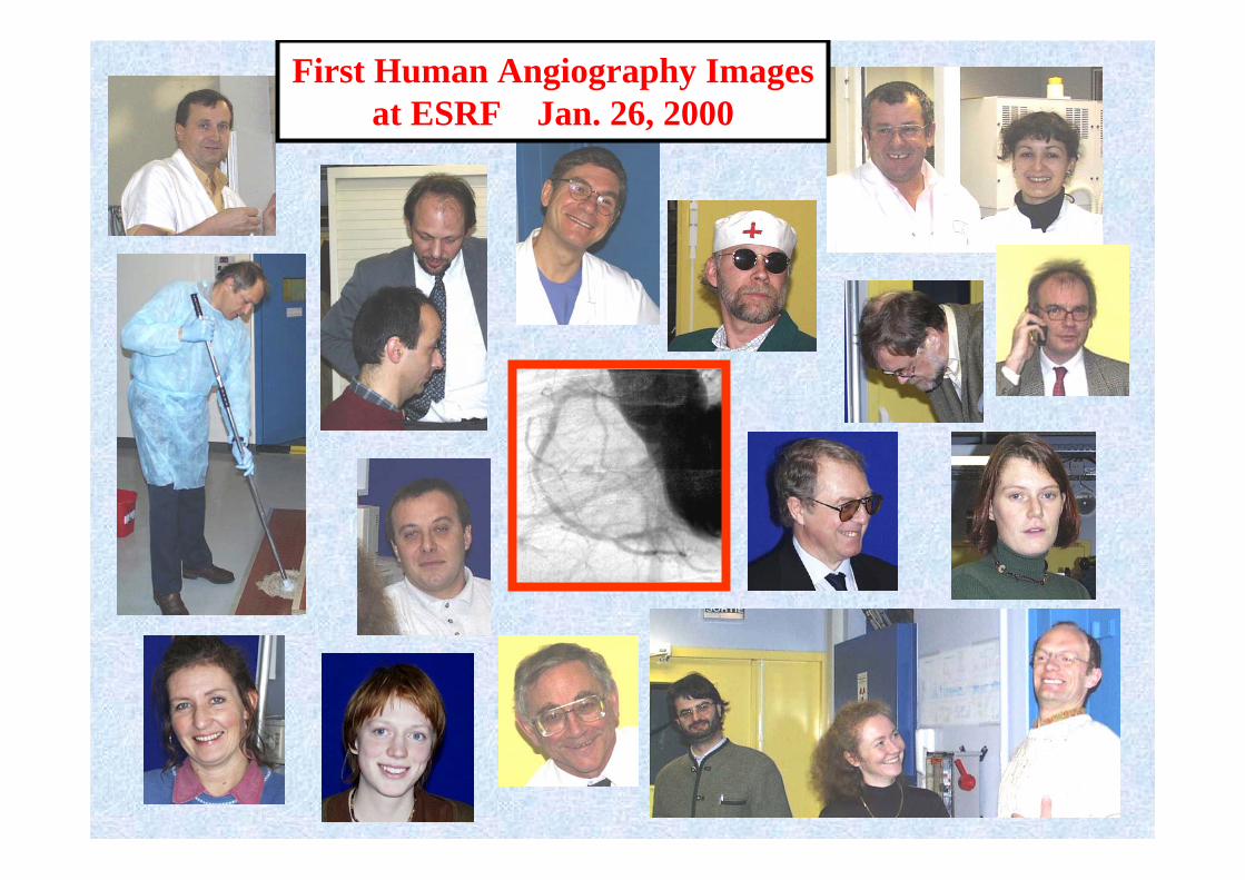
First Human Angiography Imagesat ESRF Jan. 26, 2000
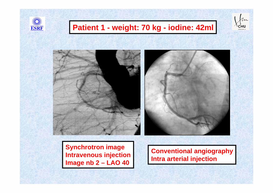
Synchrotron image Intravenous injectionImage nb 2 – LAO 40
Conventional angiographyIntra arterial injection
Patient 1 - weight: 70 kg - iodine: 42ml
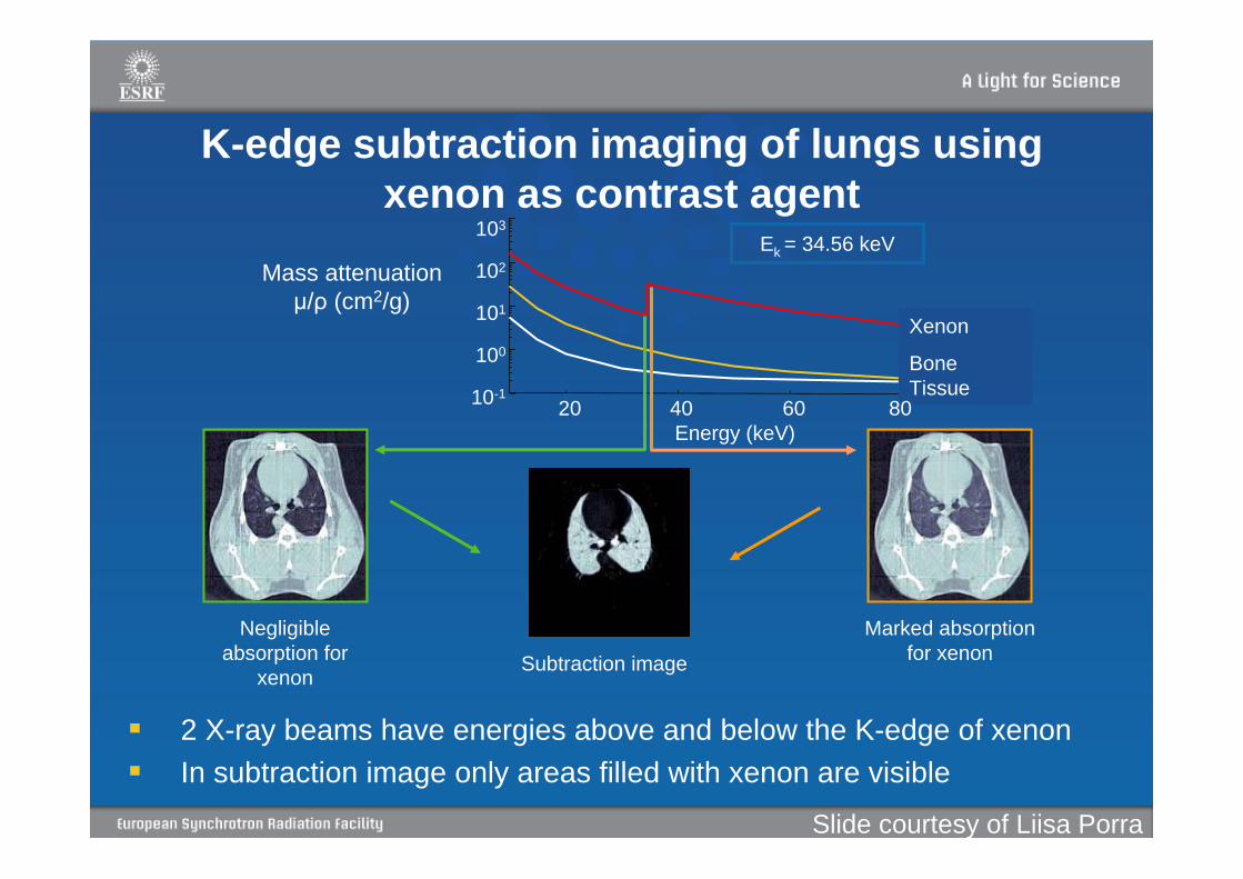
K-edge subtraction imaging of lungs using xenon as contrast agent
2 X-ray beams have energies above and below the K-edge of xenonIn subtraction image only areas filled with xenon are visible
Ek = 34.56 keV
Negligible absorption for
xenon
Marked absorption for xenonSubtraction image
103
102
101
100
10-1
Xenon
Bone Tissue
20 40 60 80 Energy (keV)
Mass attenuationμ/ρ (cm2/g)
Slide courtesy of Liisa Porra

Xe in the bronchial tree
Pixel size 0.35x0.35mm
Maximum image width 15.0 cm
Xenon in lung tissue (air spaces)
Voxel size 0.35x0.35x0.7mm3
Cross sections of the airways
Max 1 image /s
Airways
Lung tissue
Bayat et al. Phys Med Biol 2001
Projection imageCT image
In-vivo imaging of airways and lungs filled with Xe in rabbit for experimental asthma studies
Slide courtesy of Liisa Porra
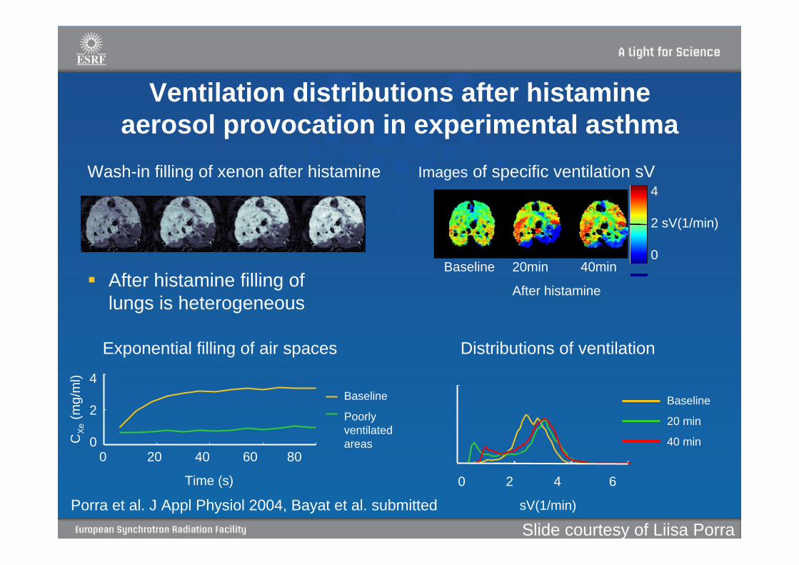
Ventilation distributions after histamine aerosol provocation in experimental asthma
Porra et al. J Appl Physiol 2004, Bayat et al. submitted
Images of specific ventilation sV
Baseline 20min 40min
After histamine
4
2 sV(1/min)
0
Wash-in filling of xenon after histamine
CXe
(mg/
ml)
0 20 40 60 80
Time (s)
4
2
0
After histamine filling of lungs is heterogeneous
Exponential filling of air spaces Distributions of ventilation
Baseline
20 min
40 min
0 2 4 6
sV(1/min)
Baseline
Poorly ventilated areas
Slide courtesy of Liisa Porra

Discovery of X-raysAbsorption Imaging
Discovery of X-raysRoentgen November 1895
X-ray of frogs1896
Medical X-rayDartmouth College
February 1896
X-ray of frog2008
Not much has changed!

Phase (wave) effects can be large in comparison with absorption!
The dream: high contrast & low dose images
Clinical Imaging Utilizes Only Absorption Information!
Object
X-rays “refracted” by object
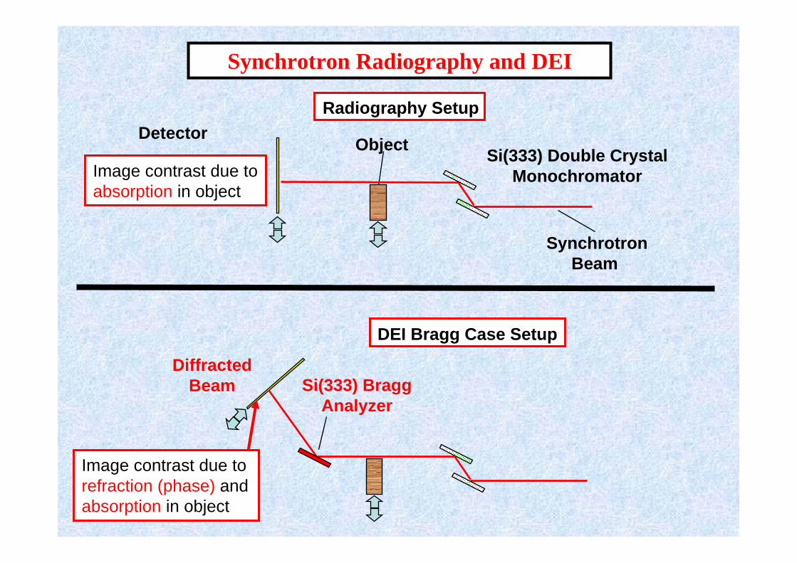
Radiography SetupDetector Object Si(333) Double Crystal
Monochromator
Synchrotron Beam
Synchrotron Radiography and DEI
Si(333) Bragg Analyzer
Diffracted Beam
DEI Bragg Case Setup
Image contrast due to refraction (phase) andabsorption in object
Image contrast due toabsorption in object
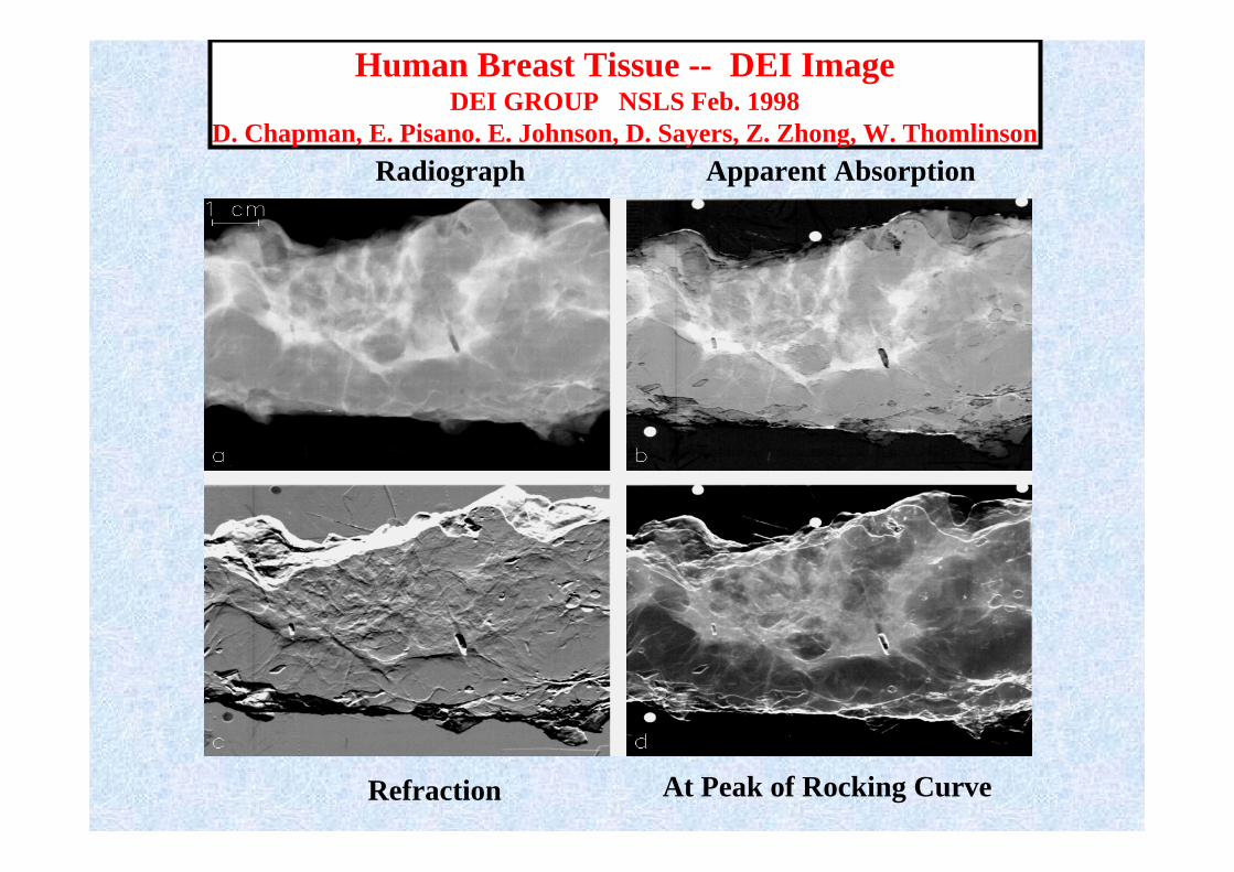
Human Breast Tissue -- DEI ImageDEI GROUP NSLS Feb. 1998
D. Chapman, E. Pisano. E. Johnson, D. Sayers, Z. Zhong, W. ThomlinsonRadiograph Apparent Absorption
Refraction At Peak of Rocking Curve
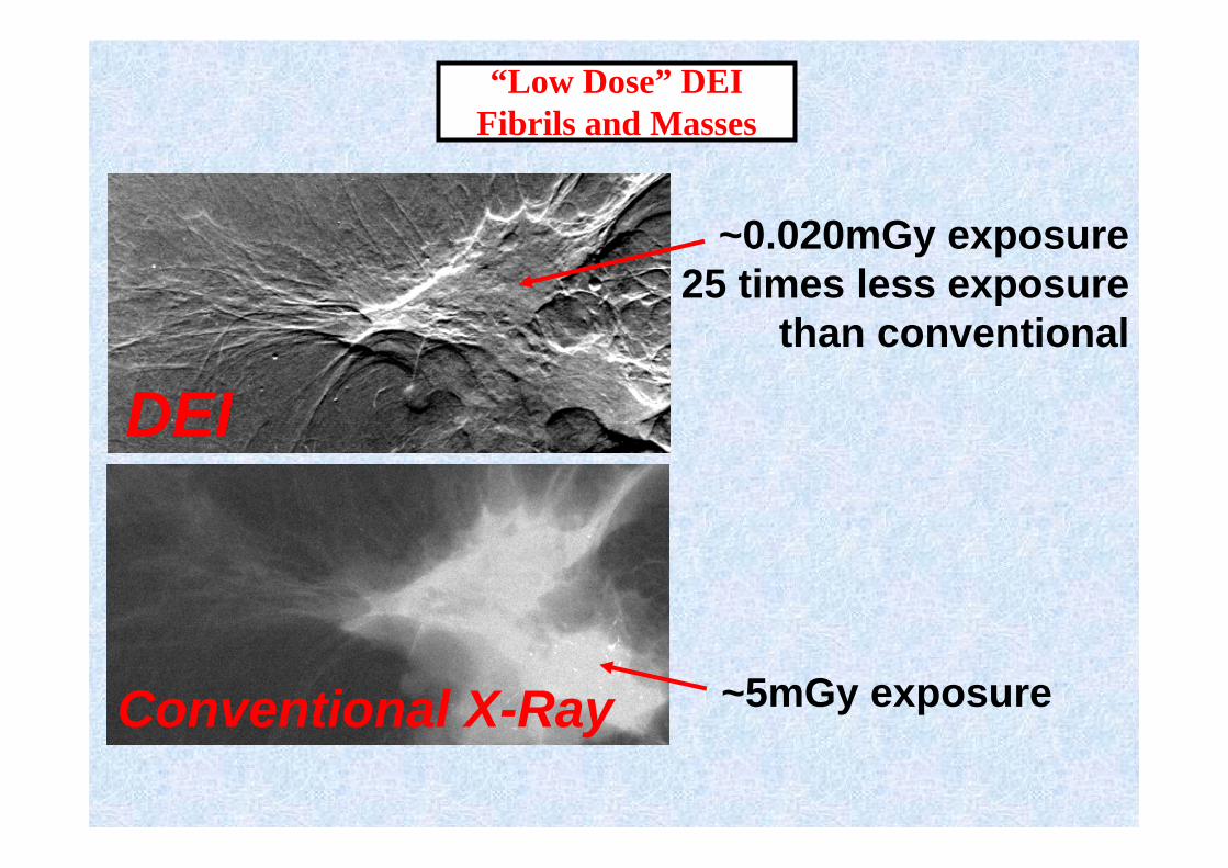
“Low Dose” DEIFibrils and Masses
~0.020mGy exposure25 times less exposure
than conventional
Conventional X-Ray ~5mGy exposure
DEI

collagen strandscollagen strands
fatfat
Ca in collagenCa in collagenskinskin--musclemuscle
Toshiba Asteion TSX - 021A80 kVp clinical CT-scanner
Histo-pathology DEI-CT (33 keV)50μm resolution
S. Fiedler, A. Bravin, J. Keyriläinen, M. Fernández, P. Suortti, W. Thomlinson, M. Tenhunen, P. Virkkunen, M-L. Karjalainen-Lindsberg, Phys. Med. Biol. 49 (2004) 175 - 188.
DEI – CT Applied to Mammography
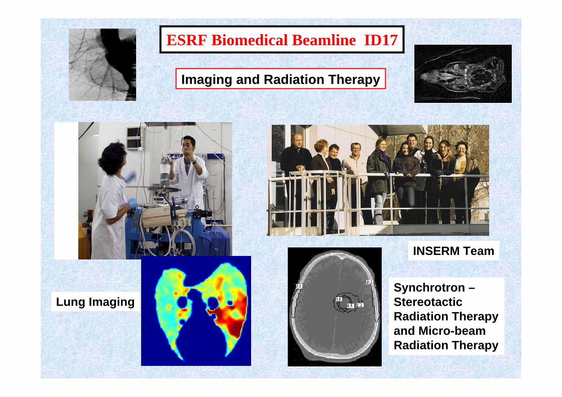
ESRF Biomedical Beamline ID17
Lung ImagingSynchrotron –Stereotactic Radiation Therapyand Micro-beamRadiation Therapy
Imaging and Radiation Therapy
INSERM Team
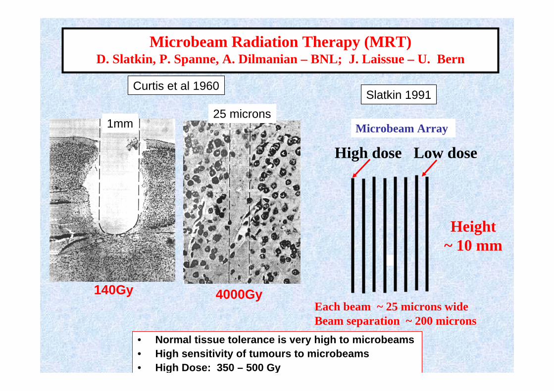
Microbeam Radiation Therapy (MRT)D. Slatkin, P. Spanne, A. Dilmanian – BNL; J. Laissue – U. Bern
• Normal tissue tolerance is very high to microbeams• High sensitivity of tumours to microbeams• High Dose: 350 – 500 Gy
Curtis et al 1960
140Gy
1mm
4000Gy
25 microns
Each beam ~ 25 microns wide Beam separation ~ 200 microns
Microbeam Array
Height~ 10 mm
High dose Low dose
Slatkin 1991
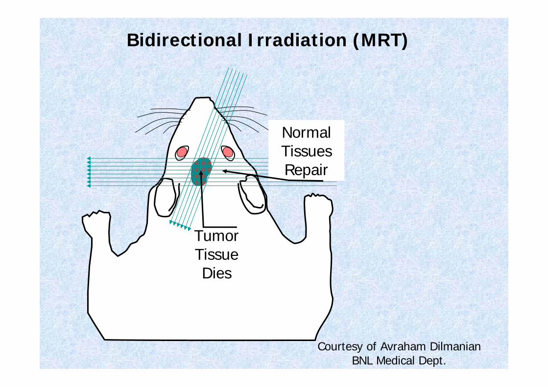
Courtesy of Avraham DilmanianBNL Medical Dept.
Bidirectional Irradiation (MRT)
Normal Tissues Repair
Tumor Tissue Dies
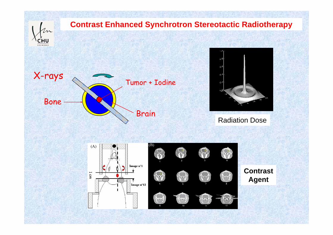
Tumor + Iodine
BoneBrain
X-rays
Contrast Enhanced Synchrotron Stereotactic Radiotherapy
Radiation Dose
ContrastAgent

Mammography , Medical Radiology, X-Ray Dosimetry
SYRMEP - ELETTRAE. Castelli

Giuliana Tromba - Elettra 36
Aim: In vivo mammography studies on cases selected by the Radiologist.
Target: Dense breasts;
conventional radiographs with uncertain diagnosis.
Set-ups: I Phase: PHC radiography with commercial detectors
II Phase: PHC imaging with digital detectors;
III Phase: low-dose tomography with custom Si microstrip detector.
Breast imaging at Elettra: the SYRMA project(SYnchrotron Radiation for MAmmography)
Agreement among the Public Hospital of Trieste, the University of Trieste and Elettra
Clinical trial started on March 13, 2006Clinical trial started on March 13, 2006
Slide courtesy of Giuliana Tromba
Giuliana Tromba - Elettra 37
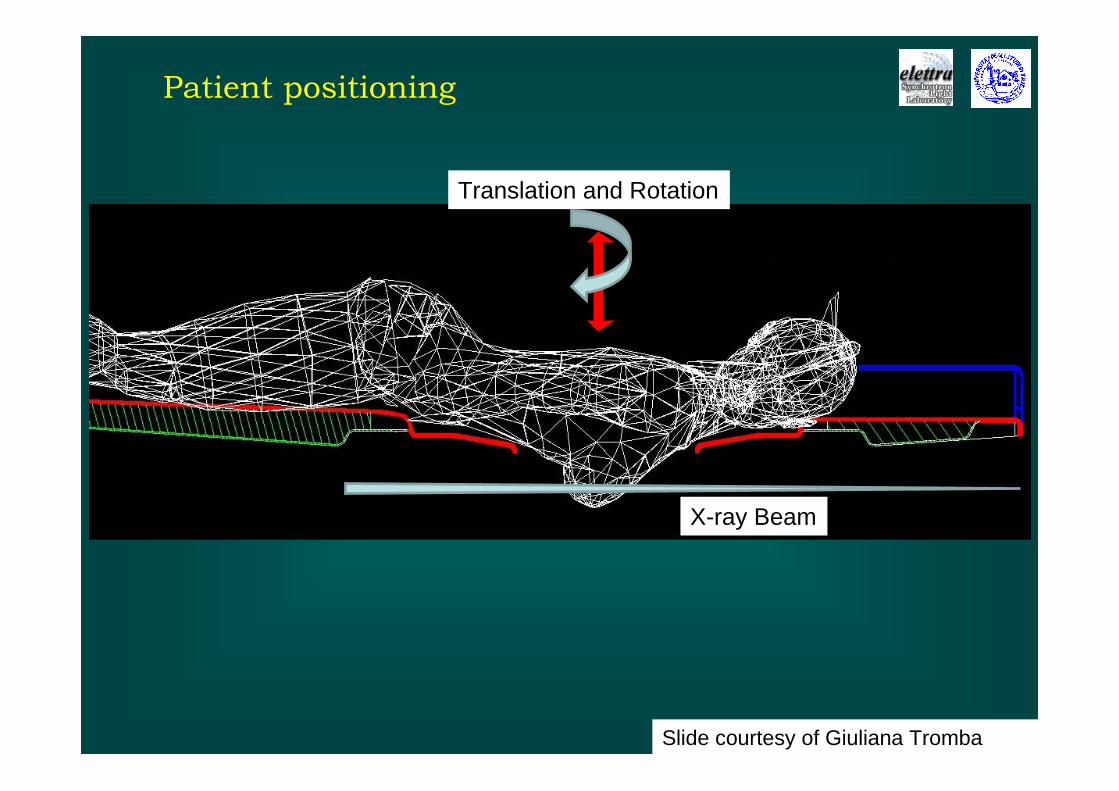
Patient positioning
Slide courtesy of Giuliana Tromba
Translation and Rotation
Translation and Rotation
X-ray Beam
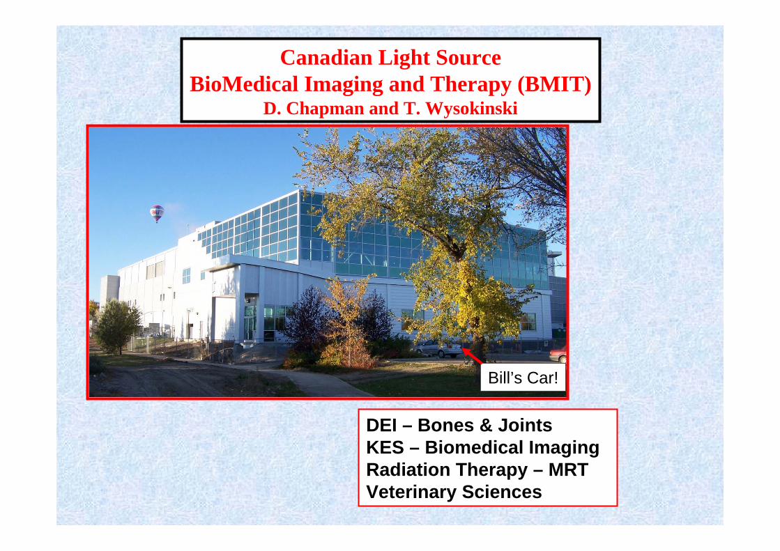
DEI – Bones & JointsKES – Biomedical ImagingRadiation Therapy – MRTVeterinary Sciences
Canadian Light SourceBioMedical Imaging and Therapy (BMIT)
D. Chapman and T. Wysokinski
Bill’s Car!
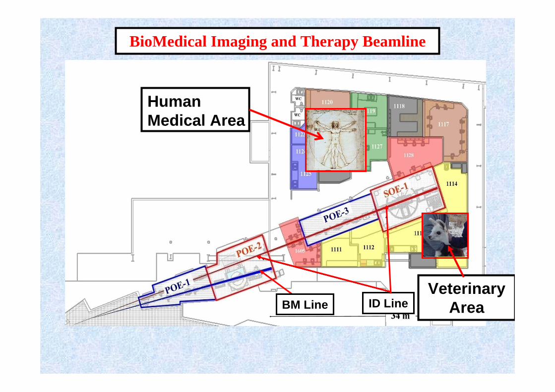
BioMedical Imaging and Therapy Beamline
HumanMedical Area
ID LineVeterinary
AreaBM Line

DEI Radiograph
Proof of principle08-09 during commissioning of BMITCadaveric specimen (soft tissue intact)
Cooper et al. Can Assoc Radiol J. 2010 Jun 29.
DEI of Trabecular Bone at the Human Wrist

Australian SynchrotronImaging and Medical Beamline (IMBL)
Daniel Hausermann and Chris Hall
Lung ImagingPhase ContrastRadiation Therapy
Australian Synchrotron
Satellite building with stations 3A and 3B – 150 m
IMBL in Experimental Hall

Imaging and Medical Beamline
Phase 3.1/3.2: 3A and 3B
Phase 2.1,2.2: 2A and 2B
Phase 1.1,1.21A and 1B
Australian Synchrotron
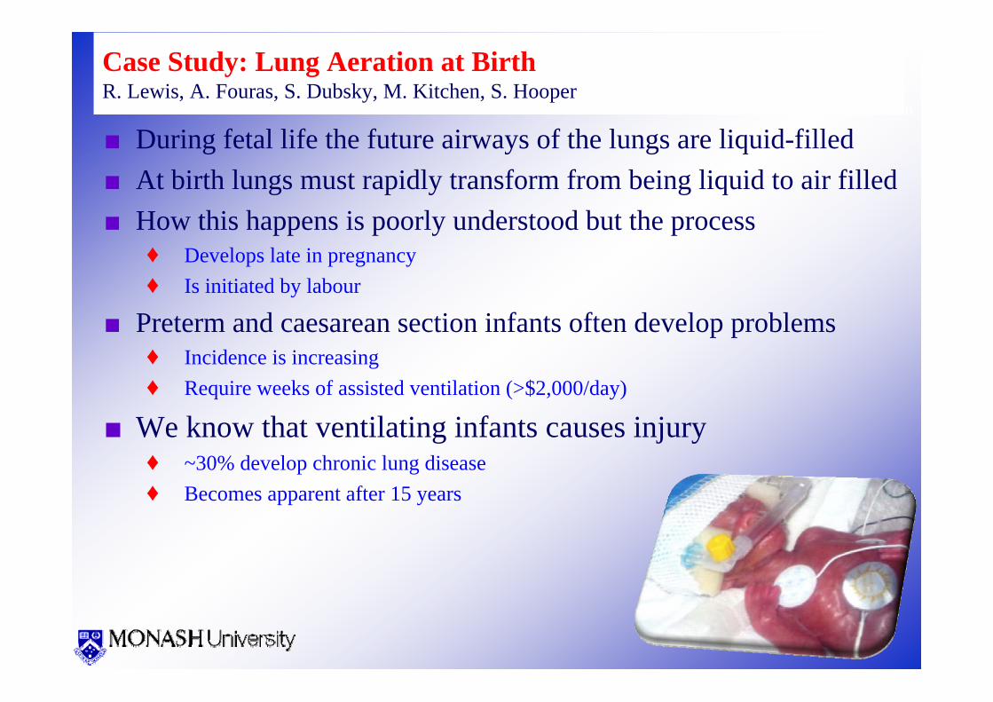
Case Study: Lung Aeration at BirthR. Lewis, A. Fouras, S. Dubsky, M. Kitchen, S. Hooper
■ During fetal life the future airways of the lungs are liquid-filled■ At birth lungs must rapidly transform from being liquid to air filled■ How this happens is poorly understood but the process
♦ Develops late in pregnancy♦ Is initiated by labour
■ Preterm and caesarean section infants often develop problems♦ Incidence is increasing♦ Require weeks of assisted ventilation (>$2,000/day)
■ We know that ventilating infants causes injury♦ ~30% develop chronic lung disease♦ Becomes apparent after 15 years

Australian Synchrotron
Phase Contrast X-ray imaging
Object Detector
Distance
Intensity
Australian Synchrotron
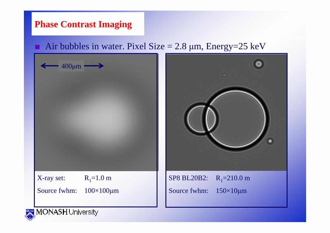
Phase Contrast Imaging
■ Air bubbles in water. Pixel Size = 2.8 μm, Energy=25 keV
X-ray set: R1=1.0 m
Source fwhm: 100×100μm
400μm
SP8 BL20B2: R1=210.0 m
Source fwhm: 150×10μm
Australian Synchrotron
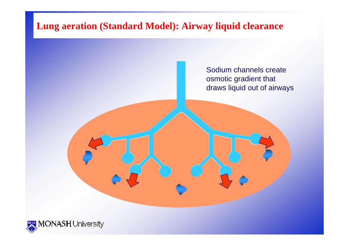
Lung aeration (Standard Model): Airway liquid clearance
Sodium channels create osmotic gradient that draws liquid out of airways

Australian Synchrotron
Lung aeration (New Model): Airway liquid clearance
Inspiration forces liquid out of airways
-P
-P
-P

KES IMAGING –CIRCULATION/VENTILATION
COMPUTEDTOMOGRAPHY –
NEUROSCIENCES
Phase IMAGINGSOFT TISSUES
RADIATION THERAPY –MRT, SSRT
DEI IMAGINGCARTILAGE &
BONES
Medical Applications of Synchrotron Radiation
Gene Expression Mapping
Preparing for Clinical
And Pre-Clinical Trials - ESRFHuman Trials Complete
SSRL, NSLS, HASYLAB,
PF, ESRF
Human Trials Possible
IMBL@AS
Human Trials In-progress
SYRMEP@ ELETTRA
Human Trials Possible
BMIT@CLS

Medical Applications of SR started with an ideaand was made possible by many talented colleagues and friends!
Thank you for your
attention!