mechanisms of giant optical nonlinearity in light-absorbing liquid
TRANSCRIPT

Mechanisms of giant optical nonlinearity in light-absorbing liquid crystals: a brief primer
LORENZO MARRUCCI
Dipartimento di Scienze Fisiche, Università di Napoli “Federico II”
& Istituto Nazionale per la Fisica della Materia Complesso di Monte S. Angelo, via Cintia, 80126 Napoli, ITALY
1. Introduction
Let us start with a very basic question that most students would ask when they first hear the terms “nonlinear optics” or “optical nonlinearity”:
What is the “optical nonlinearity”? A simple answer to this question is that an optical system is nonlinear when its optical output is a nonlinear function of its optical input. This occurs for example when light itself modifies the system “linear” optical properties, such as the refractive index, or the absorption coefficient, or the birefringence axes in the case of anisotropic materials, etc. There are however also examples of optical nonlinearities that are not conveniently interpreted as light-induced modifications of linear susceptibilities, such as second or higher-order harmonic generation, optical rectification, parametric generation, etc. [1,2]. But then, the next question that a practical-minded student would ask is
Why should one need optical nonlinearity? The most attractive reason is probably the prospect of developing all-optical systems capable of replacing electronic or electro-optical ones. This requires being able to switch or modulate light with light. A device that does so would then be called an “optical transistor” or maybe a “light valve”. Some people believe that photonics will almost completely replace electronics in the future, the advantage being that photons are faster then electrons and their transport in a transparent material does not dissipate energy into heat. And indeed in some applications this is already occurring, as for example in long-distance telecommunications. But for replacing the modern signal-processing electronic devices one would need (i) to be able to make a photonic transistor working with very low light powers, and (ii) to be able to put thousands or even millions of these transistors into a single small monolithic chip, that is to build photonic integrated circuits. This is not an easy goal, and possibly it will never be reached, at least to the point of making the replacement of electronics truly convenient. However, there are certain specific applications for which the possibility of introducing nonlinear photonic devices is more realistic. For example, one can do powerful parallel analog computations by exploiting Fourier optics, which is however usually limited to linear
L C T, 2002, V. 11, N. 3
LCT 101002
L iquid Crystals T oday ISSN 1464-5181 online © 2002 Taylor & Francis Ltdhttp://www.tandf.co.uk/journals
DOI: 10.1080/14645180110000000

calculations. Introducing in such systems some light valves one can add nonlinear calculation functionalities. These systems can be used for example in applications such as the processing of images or in simulating extended nonlinear systems. Another example of realistic application is the setting up of an all-optical feedback into an optical system, such as a laser, for example to achieve a specific pulse-shaping action (both temporal and spatial) or other special effects. Optical nonlinearity is not an exotic phenomenon. Indeed, all materials are optically nonlinear if light is sufficiently intense. One of the most common nonlinear effects is the variation of the refractive index n as a function of the light intensity I, or “nonlinear refractive index”. An equation that describes well this dependence for many materials is the following (sometimes called “Kerr-like” nonlinearity) [1,2]:
typical nonlinear refractive index: n ≈ n0 + n2 I (1.1) where the typical order of magnitude of the nonlinear coefficient n2 = dn/dI is
n2 ≈ 10-14 cm2/W. Notice that equation (1.1) is a “local” relationship, that is, the refractive index at a given point in the material depends only on the intensity of light at the same point. These values show that in order to obtain a light-induced change of refractive index of ∆n = 0.1, one needs an intensity of 10,000 GW/cm2, which is achievable only in ultrashort pulsed laser sources at peak-intensity in a focused spot. To phase-shift a light wave by a single wavelength in propagating through a nonlinear-optical material 1 mm thick, one needs a refractive index change of ∆n = 10-3, that can be achieved with an intensity of 100 GW/cm2, still requiring powerful pulsed laser sources. Therefore, for photonic applications one would like to have a much stronger nonlinearity, in order to use much weaker and possibly unfocused laser sources such as laser diodes. Thus one is led to searching materials showing extremely large nonlinearities, so-called “giant” optical nonlinearities. One class of materials that does exhibit such an extremely large nonlinear optical response is that of liquid crystals, on which we focus in this paper.
2 L. Marrucci

2. The optical nonlinearity of transparent nematic liquid crystals
The giant optical nonlinearity of nematic liquid crystals (NLC) was discovered in 1980 almost simultaneously by three groups [3,4,5]. The simplest way to observe the effects of this nonlinearity is to perform the experiment sketched in the following figure.
NLC sample
lens Laser
(Power ≈ 100 mW) nonlinear effects (self-diffraction)
This figure shows what happens when a continuous-wave laser beam of about 100 mW (for example an Argon laser, emitting in the green) is focused onto a NLC sample (having a thickness L of about 100 µm) for a proper geometry (that will be specified later on). The emerging beam expands with a very large angular divergence θ (≈ 0.1 rad) into a pattern of concentric luminous rings, which can be observed on a screen. The pattern arises because the light is diffracted on the self-generated refractive index modification occurring in the focal spot. It is a phenomenon of “self-diffraction” or “spatial self-phase-modulation”, one of the many interesting effects that can be observed with the optical nonlinearity of liquid crystals [6]. From diffraction theory we know that to acquire an angular divergence of θ ≈ 0.1 rad the center of the wavefront coming out of the NLC sample must have been retarded (or advanced) with respect to the lateral regions of the wave by about θ ω0, where ω0 is the beam waist (here ω0 ≈ 30 µm). The retardation ∆n L is therefore equal to θ ω0, from which we deduce that ∆n ≈ θ ω0 / L ≈ θ ≈ 3·10-2. The intensity in the focus is I = P/(π ω0
2) ≈ 0.3·104 W/cm2, so we obtain the
effective nonlinearity of transparent liquid crystals: n2 ≈ 10-5 cm2/W (2.1) which is 9 orders of magnitude larger than for ordinary materials! This is the good news. The bad news is that the response time of NLCs is extremely slow: a typical value for a 100 µm thick sample is τ ≈ 0.1 s. This makes this nonlinearity not well suited for applications requiring fast modulations. We must warn the readers that the nonlinearity of liquid crystals is not strictly a Kerr-like nonlinearity, as equation (2.1) would suggest. Indeed, it does not obey equation (1.1) and it is not even local. So the coefficient n2 that we give here is not a true material property but is actually geometry dependent, varying for example with the sample thickness and the beam incidence angle. The number given for n2 is a typical value for an optimal incidence angle and a sample thickness L
3Mechanisms of giant optical nonlinearity in light-absorbing L C

of about 100 µm. Thicker samples will have a larger nonlinearity (n2 scales as L2), but a much thicker NLC sample will not be very stable against nucleation of defects. Moreover the already rather slow response of the NLC becomes even slower as the thickness is increased (τ also scales as L2).
2.1 The physical mechanism
Now let us briefly illustrate the physical mechanism that governs the response of NLCs to the optical fields, leading to their giant nonlinearity. It is fundamentally similar to the well-known electro-optical response of NLCs. It can be explained as the result of the following four steps. n P
E
(i) The optical electric field E induces a polarization P that is not parallel to the field (due to dielectric anisotropy): (2.2) nP (( ⋅εε+−ε= nEE ))1 00 ε⊥ a
(Notations: n is the molecular director, εa = ε|| – ε⊥ is the dielectric anisotropy at optical frequencies, where ε|| (ε⊥) is the dielectric constant for E parallel (perpendicular) to n)
EP n
(ii) An electric torque τem develops that pulls the polari-zation and hence the director n toward the electric field direction. (2.3) EEEP ⋅εε=×=τ
r ))((0em nn ×a
(More notations: the bar above a symbol denotes an average over the optical cycle)
(iii) The director rotation is opposed by surface anchoring + bulk elasticity, and the ensuing torque balance determines the final reorientation of the molecular director n achieved at steady-state. The transient dynamics is controlled by the director rotational viscosity.
jiaijij nnδ⊥
⊥
⊥ ϑϑε+ϑε
cossin 2
||2
||eff
(iv) The rotation of molecular director n corresponds to a rotation of birefringence axes, and thus to modifying the “effective refractive index” neff seen by pure extraordinary waves and the change of light polarization suffered by a mixed ordinary-extraordinary wave. In particular, the dielectric tensor is given by (2.4) ε+ε=ε and the refractive index of an extraordinary wave propagating (2.5) along a direction k is
∧
=εε
= nk with n
4 L. Marrucci

As an example, let us consider a typical geometry that gives rise to a simple nonlinear phase retardation, similar to a Kerr-like nonlinearity: a pure extraordinary wave impinging obliquely on a homeotropic nematic liquid crystal sample, as shown in this figure.
L r
E Typical geometry for nonlinear refractive index Assuming that the angle between E and n inside the sample is the optimal angle 45°, we have:
eff
202
10em 2
||)(cn
IEEnEn aaa
ε≈εε≈×⋅εε=τ
rrrr (2.6) where I is the light irradiance and c the speed of light. For a small reorientation angle δθn of the director in the middle of the sample (where it is a maximum), the corresponding elastic torque is
nLK
δϑπ
2
2
elasticτ ≈ (2.7) where L is the sample thickness, K the splay elastic constant, and strong anchoring conditions are assumed. From imposing the torque balance τem = τelastic, one finds δθn, that is the equilibrium director rotation. This can then be used to calculate the change of refractive index by means of equation (2.5). However, one must pay attention here to the fact that the wave propagation direction k is also affected by the rotation of birefringence axes according to the usual optics of birefringent materials [7], so that the total rotation is δθ = δθn + δθk. Skipping intermediate details, we find
Wcm 10
242
25
2||
22eff
2
||
effeff2
−≈≈≈=cKLn
In
Inn aa
εεδϑ
εεδ
(2.8) The readers interested in reading more about the optical nonlinearity of liquid crystals and the resulting nonlinear effects may do so in some of the many reviews that have appeared [6,8,9,10,11].
2.2 Even larger nonlinearities
Although the nonlinearity of transparent liquid crystals is much larger than that of ordinary materials, it still requires significant laser intensities that can be achieved only with a focused continuous-wave (cw) laser. For photonic applications, however, we need to go even further, as we
Mechanisms of giant optical nonlinearity in light-absorbing L C 5
would like using unfocused light and weak laser diodes as sources. Mechanisms for achieving an even larger optical nonlinearity in liquid crystals do exist, although they require the introduction of some degree of light absorption. At the moment, the following four main classes of mechanisms have been investigated:
1. Jánossy effect and related phenomena.
2. Photorefractive nonlinearity.
3. Thermal-orientational nonlinearity.
4. Surface-driven effects.
Mechanisms 1 and 2 will be described in greater detail in section 3 and 4, respectively, while only a brief discussion will be devoted to the other two. We emphasize that all four mechanisms require using photosensitive functional dopants. The main function of these dopants is in all cases of harnessing the energy of absorbed photons and exploiting it to induce a modification of material optical properties.
L. Marrucci6

3. Jánossy effect and related phenomena
In 1990, Istvan Jánossy and his colleagues published a paper reporting the unexpected observation of large nonlinear effects in nematic liquid crystals doped with small amounts (below 1%) of certain dichroic organic dyes [12]. The effects were in all respects similar to those that had been observed in transparent materials, but they were so strong that could be easily induced by means of a He-Ne laser of few milliwatts (therefore they were characteristically colored “red” instead of the usual “green” of the Argon laser light, as shown in the following figure).
lens
dye-doped NLC
Laser (power ≈ 1 mW) Some clever experiments performed in the following years by Jánossy and coworkers demonstrated beyond any doubt that the nonlinearity was still orientational and not for example “trivially” thermal (see section 5) [13,14,15]. We recall here some of the main experimental evidence: (i) different dyes with the same absorption coefficient give rise to completely different nonlinear effects, contrary to what would be expected for thermal effects; (ii) the angular dependence of the nonlinearity was that expected for the orientational response; (iii) the relaxation time was of the right order of magnitude for an orientational response; (iv) more exotic dynamical effects occurring when the light is circularly polarized were also found to be identical to those observed in transparent materials, except for a two-orders of magnitude reduced intensity. Everything behaved as if the optical torque τo had been simply enhanced by a factor η ≈ 102 (actually its precise value depends on the dye concentration) with respect to the ordinary electromagnetic torque τem, that is
emo τητrr
= (3.1) This torque enhancement leads to a typical nonlinearity of
n2 ≈ 10-3 cm2/W Besides the enhancement of the optical torque, there are other interesting phenomenological aspects worth being mentioned:
(i) The reorientation dynamics is essentially unaffected by the presence of dye; so from the applications point of view the only “price” we pay for the enhanced nonlinearity is in the absorption losses.
Mechanisms of giant optical nonlinearity in light-absorbing L C 7

(ii) Depending on the specific dye employed, the torque can be also reversed in sign, that is one may have η < 0; in such cases the director n will tend to be reoriented perpendicular to the electric field, instead of parallel [15,16].
(iii) The torque enhancement is present only if the light wavelength lies within the absorption band of the dye. However, the wavelength dependence of the torque does not follow simply the shape of the absorption band [17,18].
(iv) A dye-induced enhancement of similar magnitude has been observed also in the isotropic liquid phase, where the orientational nonlinearity is a standard optical Kerr one [19,20,21].
(v) The enhancement effect is exquisitely sensitive to the dye molecular structure [22]; even the isotopic substitution of hydrogen atoms with deuterium leads to a further doubling of the nonlinearity [23]!
So much for the phenomenology. But what is actually going on in dye-doped liquid crystals to give rise to such a strong nonlinearity enhancement? First, one must realize that, although the dye effect appears as a multiplicative enhancement of the optical torque, as described by equation (3.1), it actually has nothing to do with the dielectric-anisotropy mechanism we have described in the previous section and that determines the optical torque τem of transparent NLCs. Indeed, an equation that better describes the actual physical situation is the following:
(3.2) The additional torque τdye contributing to the total optical torque τo is due to a completely new mechanism related to light absorption by means of the dye dopants. The reason why the overall effect is equivalent to an enhancement is that the functional dependence of τdye on n and E is identical to that of τem, that is
r r rτ τ τo em d= + ye
(3.3)))((0dye EnEn
rrrrr×⋅ζε=τ
This expression is the same as that given by equation (2.3) except for the replacement of the dielectric anisotropy εa with a new constant ζ depending on the presence of the dye. Combining equations (2.3) and (3.3.) in (3.2) and comparing the result with equation (3.1), one finds that the “apparent” enhancement factor is
η = 1 + ζ / εa (3.4) The fact that the expressions of τem and τdye are identical seems at first a quite extraordinary coincidence! However, it is not a coincidence at all, but rather the necessary result of symmetry considerations, once the following assumptions, valid for a wide class of possible mechanisms, are made [24]: the response is local in the material and optical fields (that is, it does not depend on gradients); the response is instantaneous in time (for the time scales of typical experiments) and
independent of the system history;
L. Marrucci8

the response is nonmagnetic; we consider only the lowest useful order in the optical electric field E (that is, the quadratic one,
as the linear one averages to zero owing to the optical oscillations). We note that the first assumption excludes possible coupling effects between the director and several gradients that may arise in the light-absorbing materials (such as thermal gradients, flows, etc.). The second and third assumptions are very general. The last assumption is violated when saturation of dye absorption (so-called “bleaching”) occurs. This however usually requires intensities that cannot be easily achieved using continuous-wave lasers, unless metastable states (triplet, or isomers) are excited. Therefore, equation (3.3) can be determined without need for a detailed microscopic model of the phenomenon. However, such a model is required in order to predict the value of ζ of a given material. A complete model should also explain all the phenomenology we discussed above. We note that, unlike the case of transparent NLCs where the phenomena are approximately reversible and therefore susceptible of a thermodynamic macroscopic description, here the phenomena induced by light absorption are irreversible and therefore require a fully microscopic molecular description. The first microscopic model has been proposed by I. Jánossy himself and is the object of the next section.
3.1 Jánossy’s model: description
This model was published by Istvan Jánossy in 1994 [25] (see also Ref. [24] for a critical revision) and it is based on two main processes. The first is the anisotropic photo-selection of dichroic dyes dissolved in the NLC arising because the probability of light absorption is given by p ∝ cos2α, where α is the angle between the optical electric field E and the molecule transition dipole. The latter is fixed with respect to the molecule reference frame. In many dichroic dyes it is parallel to the dye molecule long axis, and we assume so in the following.
n
ground-state molecules
Anisotropic
photo-selection n
E excited dye molecules
This photo-selection is however not enough to give rise to a torque acting on the molecular director, unless the NLC host molecules are somehow able to “tell the difference” between photo-excited and ground-state dye molecules. Indeed, the orientational distribution of the overall dye population is
Mechanisms of giant optical nonlinearity in light-absorbing L C 9
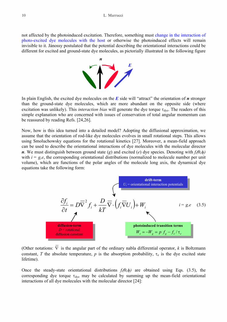
not affected by the photoinduced excitation. Therefore, something must change in the interaction of photo-excited dye molecules with the host or otherwise the photoinduced effects will remain invisible to it. Jánossy postulated that the potential describing the orientational interactions could be different for excited and ground-state dye molecules, as pictorially illustrated in the following figure n
E In plain English, the excited dye molecules on the E side will “attract” the orientation of n stronger than the ground-state dye molecules, which are more abundant on the opposite side (where excitation was unlikely). This interaction bias will generate the dye torque τdye. The readers of this simple explanation who are concerned with issues of conservation of total angular momentum can be reassured by reading Refs. [24,26]. Now, how is this idea turned into a detailed model? Adopting the diffusional approximation, we assume that the orientation of rod-like dye molecules evolves in small rotational steps. This allows using Smoluchowsky equations for the rotational kinetics [27]. Moreover, a mean-field approach can be used to describe the orientational interactions of dye molecules with the molecular director n. We must distinguish between ground state (g) and excited (e) dye species. Denoting with fi(θ,φ) with i = g,e, the corresponding orientational distributions (normalized to molecule number per unit volume), which are functions of the polar angles of the molecule long axis, the dynamical dye equations take the following form:
i = g,e (3.5) ( ) iiiii WUf
kTDfD
tf
+∇⋅∇+∇=∂∂ 2
photoinduced transition terms p eegge ffWW τ−=−= /
drift-term Ui = orientational interaction potentials
diffusion-term D = rotational
diffusion constant
(Other notations: ∇ is the angular part of the ordinary nabla differential operator, k is Boltzmann constant, T the absolute temperature, p is the absorption probability, τe is the dye excited state lifetime). Once the steady-state orientational distributions fi(θ,φ) are obtained using Eqs. (3.5), the corresponding dye torque τdye may be calculated by summing up the mean-field orientational interactions of all dye molecules with the molecular director [24]:
L. Marrucci10

( )ggee UfUfd ∇+∇×Ω= ∫ s dye sτ (3.6) Here s denotes the unit vector of a given dye orientation and the integral must be taken over the whole solid angle. By this approach, one finds that a torque will arise only if Ue ≠ Ug, that is only if excited dye molecules interact with the host differently from ground-state ones. The dye dynamics can be visualized as a random walk on the sphere of possible orientations. In the limit case of very strong (with respect to thermal agitation) excited-state potential (Ue >> kT) and vanishing ground-state potential (Ug << kT), one has the situation depicted in the following figure [26]:
n E
Rotational drift driven by
mean-field
Excitation by photon absorption
Orientational random walk
In this limit case, the torque on the director arises from excited-state dye molecules only (because Ug ≈ 0), as a reaction to the torque causing their rapid drift toward the director (here located at the “north pole”). We conclude this section by mentioning that an interesting analogy of this model with those developed to describe biological molecular motors has been recognized by Peter Palffy-Muhoray and Weinan E [28].
3.2 Jánossy’s model: quantitative comparison with experiment
The main prediction of Jánossy’s model is the value of ζ, giving the magnitude of the dye torque (see equation (3.3)). However, this quantity depends on the dye concentration and on the cross-section for light absorption. To characterize the single-dye-molecule efficiency in contributing to the torque after the absorption of a photon, the following merit figure µ has been introduced [29]:
(3.7) µ
ζα α
=+( )n ne e o o2 λS
Here λ is the light wavelength, S the NLC order parameter, ne = ||ε (no = ⊥ε ) is the refractive
index for a pure extraordinary (ordinary) wave, and αe (αo) is the corresponding absorption
Mechanisms of giant optical nonlinearity in light-absorbing L C 11

coefficient. For sufficiently small dye concentration, µ is independent both of it and of the dye absorption cross-section [29]. To predict the value of µ one must solve numerically the equations of Jánossy’s model. However, in the limit of small dye anisotropy, an analytical solution can also be found, which is at least useful for identifying the important microscopic parameters. This solution is as follows: ground-state orientational
dye mean-field energy
(3.8) In this expression, we assumed the form Ui(θ) = ½ ui cos2θ (where θ is the angle between the dye molecule axis s and the director n) for the mean-field potentials, that is the simplest compatible with the system symmetry. Therefore the lower-case u’s in equation (3.8) (and in the following) denote the mean-field energy coefficients characterizing the strength of the orientational interactions. Now, τe and D can be determined from time-resolved fluorescence. Typical values are τe ≈ 1 ns and D ≈ 0.1 ns-1. The ground-state energy coefficient ug determines the dye equilibrium orientational distribution and can be obtained from the measured dichroism (that is from the absorption anisotropy, given by αe and αo). A typical value is ug ≈ 0.5 eV. However ue cannot be easily determined experimentally and so far nobody has determined it independently of µ itself. Therefore we cannot currently predict the precise value of µ within the framework of this model. What we can do is only verifying if the numbers are reasonable. However, this is best done using more precise numerical calculations to solve the model equations. Plotting the results obtained for different values of ue (relative to ug) versus the dimensionless factor mg = ugS/2kT that characterizes the orientational equilibrium anisotropy in the dye ground state, one obtains the following plot:
( )µτ
τ=
+
−
215 1 6h D
u ue
ee g
Excited-state lifetime
Planck constant
Rotational diffusion constant excited-state orientational
dye mean-field energy
0 2 4 6 8 10-2
0
2
4
0.8
1.21.5
2
ue /ug = 2.5
µ×
100h
DS
kT
u SkTg
2
Experimentalvalues
Experimentalvalues
0 2 4 6 8 10-2
0
2
4
0.8
1.21.5
2
ue /ug = 2.5
µ×
100h
DS
kT
u SkTg
2
0 2 4 6 8 10-2
0
2
4
0.8
1.21.5
2
ue /ug = 2.5
µ×
100h
DS
kTµ
×
10
0hD
SkT
u SkTg
2
Experimentalvalues
Experimentalvalues
Experimentalvalues
Experimentalvalues
0.50.50.5
L. Marrucci12

The yellow dots in the figure are two experimental values of the Jánossy effect for two different NLCs having different order parameter (5CB, see section 3.4 for its molecular structure, and E63, cyanophenyl nematic mixture produced by Merck). This plot shows that Jánossy’s model predicts correctly the order of magnitude of the dye torque. However, the model is not quantitatively right when it comes to a more precise prediction. In particular, for higher values of mg the predicted merit figure (and therefore the dye torque) vanishes exponentially, and therefore it cannot account for experimental values for any reasonable choice of the molecular parameters.
3.3 State-dependent mobility model
A way to solve this problem was proposed by D. Paparo and myself in 1997 by generalizing Jánossy’s model [24]. The idea is rather simple. Instead of assuming that the main difference between excited and ground state dye molecules is in the mean-field potentials Ui’s, we formed the hypothesis that what actually changes during electronic excitation is the rotational diffusion constant D of the dye molecules. In other words we assumed that D De g≠
Excited statediffusion constant
Excited statediffusion constant
Ground statediffusion constant
Ground statediffusion constant
D De g≠Excited state
diffusion constantExcited state
diffusion constantExcited state
diffusion constantExcited state
diffusion constantGround state
diffusion constantGround state
diffusion constantGround state
diffusion constantGround state
diffusion constant
But why should this fact contribute to the dye torque? One can gain a qualitative insight into the mechanism generating the torque in the limit Dg >> De by looking at the following schematic figure.
rE
rn
Dye moleculesoriented as Eare excited
Ground-statemoleculesdiffuse fasterto equilibrium
rE
rn
There are moremolecules on theE side
Torque
rE
rn
Dye moleculesoriented as Eare excited
rE
rn rE
rn
Dye moleculesoriented as Eare excited
Ground-statemoleculesdiffuse fasterto equilibrium
Ground-statemoleculesdiffuse fasterto equilibrium
rE
rn
There are moremolecules on theE side
rE
rn rE
rn
There are moremolecules on theE side
TorqueTorque
As we see, the combined kinetic processes of photo-excitation and state-dependent diffusion give rise to a net accumulation of dye molecules (both ground-state and excited) having the same orientation as the optical field E (for Dg < De, the accumulation is instead in a plane orthogonal to E). This anisotropic orientational distribution of the whole population of dye molecules then gives rise to the torque via the mean-field potentials Ui (and this occurs even if Ue = Ug).
Mechanisms of giant optical nonlinearity in light-absorbing L C 13

The rotational diffusion constant D of a molecule is linked, via Einstein’s relation, to the rotational mobility D/kT and to its inverse, the rotational molecular friction coefficient kT/D. Thus one can also say that the fundamental driving force for the dye torque in this model is a light-induced modulation of molecular mobility or friction. This mechanism can be linked again to the subject of molecular motors, giving rise to a new model of “fluctuating-friction” molecular motors [30,31]. The rotational molecular mobility is determined by the strength and nature of the intermolecular interactions (not only the anisotropic ones) between the dye and liquid crystal solvent, so this model can be considered as a straightforward variant of Jánossy’s one. Formally, its main equations are still Eqs. (3.5) and (3.6), after replacing D with a state-dependent constant Di. One can also combine the two contributions of a state-dependent mean-field potential and diffusion constant. The small dye anisotropy approximation then leads to the following expression for the torque merit figure (generalizing Eq. 3.8):
µτ
τ=
+
−
215 1 6h
DD
uD
uD
e e
e e
e
e
g
g
(3.9) This expression, as Eq. (3.8), is useful for identifying the role of the different molecular parameters. To make a quantitative comparison with experiments is instead necessary to perform numerical calculations. In the case ug = ue and Dg ≠ De, the torque merit figure versus the dye-anisotropy parameter mg is now given by the following graph.
0 2 4 6 8 10-8
-6
-4
-2
0
2
4 Dg /De
2.52
1.51.20.8
Dg /De
2.52
1.51.20.8
u SkT
g2
µ×
100h
DS
kT
0 2 4 6 8 10-8
-6
-4
-2
0
2
4 Dg /De
2.52
1.51.20.8
Dg /De
2.52
1.51.20.8
u SkT
g2
µ×
100h
DS
kTµ
×
10
0hD
SkT
0.50.50.50.5 where the yellow dots are the experimental values (the same as in the previous graph). Interestingly, the exponential decay for large values of mg is now replaced by a much slower power-law decay. This behavior is best understood by the molecular-motor analogy, as discussed in Ref. [30,31]. As a consequence, we find now that data can be quantitatively explained if we assume Dg/De ≈ 2. This mobility state-dependence is large but not unreasonable. Indeed, in the literature one finds a few (but only a few) examples of molecules having a rotational mobility that is strongly dependent on the electronic state, even by a factor two [32,33,34]. Moreover, kinetic coefficients such as the rotational mobility are usually “activated quantities”, that is, they exhibit an Arrhenius temperature dependence. More precisely, a kinetic ab initio theory [35]
L. Marrucci14

shows that the rotational mobility of a rod-like molecule in a liquid crystal solvent can be cast in the following form:
D D eE E
kT=−
+
0
0 1
Isotropic interactionenergy (E0 ∼ 10 kT )Isotropic interactionenergy (E0 ∼ 10 kT )
Anisotropic energy(E1 ∼ 1 kT )
Anisotropic energy(E1 ∼ 1 kT )
D D eE E
kT=−
+
0
0 1
Isotropic interactionenergy (E0 ∼ 10 kT )Isotropic interactionenergy (E0 ∼ 10 kT )Isotropic interactionenergy (E0 ∼ 10 kT )Isotropic interactionenergy (E0 ∼ 10 kT )
Anisotropic energy(E1 ∼ 1 kT )
Anisotropic energy(E1 ∼ 1 kT )
Anisotropic energy(E1 ∼ 1 kT )
Anisotropic energy(E1 ∼ 1 kT )
Here D0 is a prefactor that is non-exponentially dependent on temperature T. The energy E0+E1 is called “activation energy”. At room temperature D may be very sensitive to the activation energy. A change ∆E0 / E0 ≈ 10% yields Dg /De ≈ 2 (neglecting the dependence of D0 on E0) This shows that the rotational mobility may be very sensitive to changes of intermolecular forces and supports the plausibility of a strong internal-state dependence. Finally, as shown by Eq. (3.9), the dye torque can be also explained by a combined photoinduced change of mean-field energy u and rotational diffusion constant D (in which case smaller photo-induced changes would be required for each quantity). It could be possible to distinguish these two contributions by fitting the measured temperature dependence of Jánossy effect (however one has to introduce some additional assumptions about the temperature dependence of ui and Di). This was accomplished in Ref. [29], with the following results:
µ
20 30 40 50 60 70 800
500
1000
1500
2000
2500
3000
T (°C)
µ
20 30 40 50 60 70 800
500
1000
1500
2000
2500
3000
T (°C)
µ
20 30 40 50 60 70 800
500
1000
1500
2000
2500
3000
T (°C)
uu
e
g= 133.
∆EE
0
0
4 520
==
.% kJ / mol
DD T
g
e=
= °14
20. for
C
uu
e
g= 133.
∆EE
0
0
4 520
==
.% kJ / mol
DD T
g
e=
= °14
20. for
C
uu
e
g= 133.
∆EE
0
0
4 520
==
.% kJ / mol
DD T
g
e=
= °14
20. for
C
These results for the ratios ue/ug and Dg/De are quite reasonable. However, we cannot consider them yet as a “final” proof of the correctness of the described model. Such a proof would need an independent measurement of ue/ug and of Dg/De, not deriving from the Jánossy effect itself. This measurement is possible in principle by using techniques of time-resolved optical spectroscopy, although for several reasons it is not a simple task. Only very recently, an independent measurement
Mechanisms of giant optical nonlinearity in light-absorbing L C 15

of the ratio Dg/De was accomplished for some selected materials exhibiting a strong Jánossy effect [36]. The obtained ratio was Dg/De = 1.4±0.1, in good agreement with what needed to explain the observed Jánossy effect for the employed light wavelengths (even assuming ug = ue). We believe that this last result, if confirmed, proves that the correct explanation for the Jánossy effect must be certainly based on the photoinduced change of rotational mobility of dye molecules. An additional contribution from the photoinduced change of mean-field orientational potential is likely, although its magnitude is still uncertain.
3.4 What happens inside a dye molecule
So we have seen that to explain the large dye-induced optical torque in Jánossy effect we need a large photoinduced variation of dye-solvent intermolecular interactions. But what could actually occur inside a dye molecule to make it change so much in the photo-excited state? This question is also a question on the nature of the photo-excited state actually involved in the mechanism described in the previous sections. Is it the electronic excited singlet state (commonly labeled S1, while the ground state is labeled S0) excited immediately by the photon absorption, or rather some more exotic state (such as a long-lived conformation isomer, a tautomer, or a triplet state) that takes over shortly afterwards? Actually, there is a wide class of dye molecules, the “azo dyes”, that are known to undergo trans-cis conformational isomerization as a result of photo-excitation, corresponding to a large photoinduced change of molecular shape, as shown in the figure on the side. This large change of conformation can obviously account for a large change of intermolecular interactions. And indeed many azo dyes are very effective in Jánossy effect, although they almost always give rise to “negative” torques (that is with ζ < 0). Azo dyes attracted a great deal of attention in the last years, because under polarized illumination they proved capable of reorienting the molecules of materials that are much more “rigid” than liquid crystals, such as glassy polymers and thin solid molecular films [37]. In these materials the photoinduced reorientation can be permanent, and therefore suitable for applications in fields such as optical storage, material optical processing, etc.
NN
NN
trans
cis
NN
NN
NN
NN
trans
cis
O
O
N HH
1-amino-anthraquinone
O
O
O
O
N HHN HH
1-amino-anthraquinone
However, among the most effective dyes giving rise to the Jánossy effect in liquid crystals are anthraquinone dyes, which are known not to undergo photoisomerization, nor other large photoinduced conformational transformations (they were also the first dyes used by Jánossy when he made his discovery). Moreover, they are the only known dyes for which ζ > 0 (although azo dyes in their metastable cis form seem to exhibit positive effects too). One of the simplest examples of these dyes is the 1-amino-anthraquinone (1AAQ), shown in the figure on the side (the anthraquinone core is in black, the substituent amino group in red).
L. Marrucci16
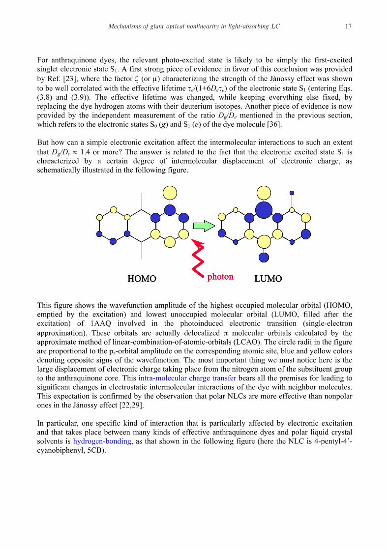
For anthraquinone dyes, the relevant photo-excited state is likely to be simply the first-excited singlet electronic state S1. A first strong piece of evidence in favor of this conclusion was provided by Ref. [23], where the factor ζ (or µ) characterizing the strength of the Jánossy effect was shown to be well correlated with the effective lifetime τe/(1+6Deτe) of the electronic state S1 (entering Eqs. (3.8) and (3.9)). The effective lifetime was changed, while keeping everything else fixed, by replacing the dye hydrogen atoms with their deuterium isotopes. Another piece of evidence is now provided by the independent measurement of the ratio Dg/De mentioned in the previous section, which refers to the electronic states S0 (g) and S1 (e) of the dye molecule [36]. But how can a simple electronic excitation affect the intermolecular interactions to such an extent that Dg/De ≈ 1.4 or more? The answer is related to the fact that the electronic excited state S1 is characterized by a certain degree of intermolecular displacement of electronic charge, as schematically illustrated in the following figure.
HOMO photon LUMOHOMOHOMO photonphoton LUMOLUMOLUMO
This figure shows the wavefunction amplitude of the highest occupied molecular orbital (HOMO, emptied by the excitation) and lowest unoccupied molecular orbital (LUMO, filled after the excitation) of 1AAQ involved in the photoinduced electronic transition (single-electron approximation). These orbitals are actually delocalized π molecular orbitals calculated by the approximate method of linear-combination-of-atomic-orbitals (LCAO). The circle radii in the figure are proportional to the pz-orbital amplitude on the corresponding atomic site, blue and yellow colors denoting opposite signs of the wavefunction. The most important thing we must notice here is the large displacement of electronic charge taking place from the nitrogen atom of the substituent group to the anthraquinone core. This intra-molecular charge transfer bears all the premises for leading to significant changes in electrostatic intermolecular interactions of the dye with neighbor molecules. This expectation is confirmed by the observation that polar NLCs are more effective than nonpolar ones in the Jánossy effect [22,29]. In particular, one specific kind of interaction that is particularly affected by electronic excitation and that takes place between many kinds of effective anthraquinone dyes and polar liquid crystal solvents is hydrogen-bonding, as that shown in the following figure (here the NLC is 4-pentyl-4’-cyanobiphenyl, 5CB).
Mechanisms of giant optical nonlinearity in light-absorbing L C 17

O
O
N HH
CN C5H11
hydrogen bondinghydrogen bonding
O
O
O
O
N HHN HH
CN C5H11CN C5H11
hydrogen bondinghydrogen bondinghydrogen bondinghydrogen bonding By enhancing the strength of hydrogen bonding, the photoinduced excitation is likely to lead to both an increase of mean-field energy u and a decrease of rotational diffusivity D, both effects which would contribute to the Jánossy effect as explained in the previous sections.
3.5 To summarize
Generally speaking, we may say that Jánossy effect belongs to a class of photophysical effects based on the photoinduced reversible change of intermolecular interactions, amplified by the sensitive orientational response of the host (NLC). A typical example of this class of effects is that based on the photoinduced conformational transformations (azo-dyes). Known effects are photoinduced alignment of polymers and Langmuir films, and photoinduced nematic-isotropic transitions. These effects are apparently always “negative”: they favor a molecular alignment orthogonal to the optical electric field. In Jánossy effect, we seem to have an example of a more subtle mechanism: electronic excitation alone modifies hydrogen-bond interactions, and this affects a sensitive kinetic coefficient, namely dye rotational mobility. A molecular-motor-like mechanism transduces this into a torque acting on the director. This is currently the only known mechanism for a “positive” photoinduced torque. We may conclude this section by noting that even in the important case of azo dyes, relevant for many photoinduced orientation effects in organic materials suitable of being used in applications, photoisomerization is probably not the whole story. Molecular effects somehow related with the sole electronic excitation similar to what has been found with anthraquinone dyes could play a role whose significance is still to be established. This is the subject of current research.
L. Marrucci18

4. Photorefractive liquid crystals
The photorefractive nonlinearity effect in liquid crystals has been predicted and experimentally demonstrated for the first time in 1994 by E. V. Rudenko and A. V. Sukhov [38] (followed shortly afterwards by I. C. Khoo and colleagues [39]). It is an indirect effect based on the following three main steps: (i) Photoinduced generation of space charge in form of ions.
(ii) Charge separation by diffusion generating a dc electric field (iii) Electro-optic response to this dc field giving rise to a refractive
index modulation
This phenomenon is well known for certain solid-state materials (such as semiconductors), in which it gives rise to one of the highest known nonlinearities [2]. However, liquid crystals have the potential to develop an extremely large photorefractive nonlinearity, owing to their strong electro-optic response. Let us now see how it works in more detail, in the specific case of nematic liquid crystals (NLC). The next figure shows schematically what occurs when a single laser beam crosses a liquid crystal cell. The photoinduced generation of space charge may arise from photochemical effects or photo-ionizations that can take place in suitable dopants (although smaller effects are possible even in pure NLCs, due to impurities).
laserbeamlaserbeam
Photoinducedcharge generation
(in dyes or impurities)
Photoinducedcharge generation
(in dyes or impurities)
laserbeamlaserbeamlaserbeamlaserbeam
Photoinducedcharge generation
(in dyes or impurities)
Photoinducedcharge generation
(in dyes or impurities)
However, the generated positive and negative ions are uniformly distributed in the illuminated region of the sample (neglecting the small intensity gradients associated with the beam profile). The
Mechanisms of giant optical nonlinearity in light-absorbing L C 19

subsequent ionic diffusion will not affect this uniform distribution, so there is no mechanism acting to separate charge and thus giving rise to electric fields. Therefore, the photorefractive nonlinearity is negligible for a single laser beam (although a small effect may actually take place due to intensity gradients, especially for strongly focused beams). To obtain charge separation, we need to have a strongly nonuniform light. This is conveniently achieved when two coherent laser beams overlap and thus create an interference intensity grating in the sample, as shown pictorially in the following figure.
two laserbeams
two laserbeams
Charges are generatedin the maxima of
interference fringes
Charges are generatedin the maxima of
interference fringes
two laserbeams
two laserbeamstwo laser
beamstwo laser
beams
Charges are generatedin the maxima of
interference fringes
Charges are generatedin the maxima of
interference fringes
In this case, ions are generated preferentially in the maxima of interference fringes. The subsequent diffusion of these ions out of these regions can then give rise to separation of opposite charges, owing to the different values of the diffusion constant of positive and negative ions. For example, in the limit case in which positive ions have very low mobility and negative ions a very high one, one would obtain a situation as that depicted in the following figure.
A different diffusion rategives rise to separation
(here + are slow and – are fast)
A different diffusion rategives rise to separation
(here + are slow and – are fast)
A different diffusion rategives rise to separation
(here + are slow and – are fast)
A different diffusion rategives rise to separation
(here + are slow and – are fast)
L. Marrucci20

It can be seen that positive ions are still preferentially located in the stripes of high light intensity, while negative ions have assumed a more uniform distribution. The separation of opposite charges corresponds to the formation of a net charge density grating which, in turn, originates a dc electric field grating, as illustrated in the next figure.
A dc field gratingis thus generated
A dc field gratingis thus generatedA dc field gratingis thus generated
A dc field gratingis thus generated
This internally generated dc field alone could already give rise to a nonlinear refractive index modulation via the electro-optical response of the material. In most cases, however, to obtain an effective nonlinearity one must add also a large longitudinal dc field (the reasons for this are discussed later), as shown in the next figure.
Mechanisms of giant optical nonlinearity in light-absorbing L C 21

The total dc electric field resulting from the external one and the internally generated space-charge field then drives the molecular director reorientation, as illustrated in the following figure. This director modulation is seen by extraordinary light waves propagating in the sample as a nonlinear refractive index grating. This step completes our pictorial description of the photorefractive nonlinearity mechanism. Let us now discuss the reasons for adding the external dc field. The first motivation is common to all photorefractive materials: the directional drift processes driven by the external field may enhance the space charge separation that would be obtained by random diffusion only [2]. However this effect is greatest when the external field is transverse to the grating (that is parallel to the grating wave-vector), which is far from the geometry we have described. The reasons for adding a longitudinal dc field are instead specific of liquid crystalline materials and are related to the fact that the dominant electro-optic response of liquid crystals, unlike the case of other photorefractive materials, is quadratic (instead of linear) in the electric field (because it is controlled by a torque analogous to that of Eq. (2.3)). Now, it is easy to verify that the space-charge-generated electric field Es is modulated approximately as the interference grating, that is Es = E0 cos(q x′), where x′ is an axis along the modulation direction and q = |k2 – k1|, k1 and k2 being the wave-vectors of the two interfering beams. Then, the index modulation induced in the sample in the absence of external field is δn ∝ Es
2 ∝ cos2(q x′) = ½ + ½ cos(2 q x′) that has a spatial frequency 2q. It can be shown that such an index modulation is ineffective for the nonlinear coupling effects (such as mutual phase modulation, energy transfer, etc. [2]) between the two laser beams. Effective coupling requires instead the validity of the so-called phase-matching condition, corresponding to having a refractive index modulation with spatial frequency q. When the external dc field Eext is added, the index modulation is given by δn ∝ E2 = (Eext + Es)2 = Eext
2 + 2 Eext Es + Es2 = Eext
2 + 2 Eext E0 cos(q x′) + E0
2 cos2(q x′). The second term in the last expression is then modulated with spatial frequency q and thus provides a good phase matching. Moreover, if Eext >> E0, the index modulation given by the
L. Marrucci22

term 2 Eext Es is much larger than that given by the term Es2, and the overall nonlinearity is
therefore enhanced. The next figure summarizes all the gratings involved in the process (assuming, as an example, that negative ions have a greater mobility than positive ones):
x′
I
ρ+, ρ-
ρ = ρ+- ρ-
Es
δneff ∝ δθx′
I
ρ+, ρ-
ρ = ρ+- ρ-
Es
δneff ∝ δθ
Here δθ denotes the angle of director rotation and the refractive index variation δneff is proportional to it, as in Eq. (2.8). An interesting point to be noticed here is that the refractive index grating is shifted by a quarter of period (corresponding to a phase-shift of π/2) with respect to the light intensity I grating. This nonlocal behavior, characteristic of photorefractive nonlinearity, is especially important as it makes possible the phenomenon known as beam coupling (that is the process of energy transfer between the two interfering light beams) [2], which is otherwise forbidden for local nonlinearities (it is actually still possible if the phase shift occurs in time instead of in space, but this may occur only when the two beams have different frequencies [2]). It must be also added that these energy transfer processes may also trigger amplification of a new light beam starting from noise only. Therefore the need to have two interfering beams in the input is removed, if the nonlinearity is sufficiently strong. A single input beam may spontaneously give birth to one or more output beams. In this case, one usually talks of stimulated light scattering [1,2]. Finally, we must warn the readers that what has been described here is only the simplest and most basic scheme for the photorefractive nonlinearity. Other more complex phenomena may contribute to it, or add to its complexity. We mention, for example, that dielectric and conductivity liquid crystal anisotropies in a suitably inhomogeneous configuration may act as additional sources of space charge, independent of photoionization processes. Dc electric fields and space charging may also trigger fluid flow, which in turn is coupled to all other material anisotropies. We refer the interested readers to the works by I. C. Khoo and his colleagues [39,40].
Mechanisms of giant optical nonlinearity in light-absorbing L C 23

Although photorefractive nonlinearity is very different from Kerr-like nonlinearities, one can still characterize its strength by means of an n2 coefficient, defined in this case as the ratio of refractive index to intensity modulation amplitude. In this case one has the following
typical strength of photorefractive nonlinearity n2 ≈ 10-2-10-1 cm2/W This figure is typical for the materials investigated so far, and for concentrations low enough that the absorption coefficient remains reasonably small (≈ 1-10 cm-1). However, it must be emphasized that no systematic material optimization has been attempted so far. There may be a significant potential for optimization, especially based on increasing the difference in the mobilities of opposite ionic species. The already very large value of n2 and the potential for further improving makes of the photorefractive nonlinearity perhaps the most promising current candidate for applications based on liquid crystal giant optical nonlinearity. However, further research is still needed, in particular to solve material problems such as the limited photostability of dyes and the presence of unwanted irreversible effects.
L. Marrucci24

5. Photothermal-orientational effects
Light absorption always gives rise to local heating and this in turn may induce different effects related with molecular order, among which the so-called thermal-indexing, that is the change of refractive index due to heating. Although this simple indirect nonlinear phenomenon is common to all absorbing materials, liquid crystals are special under many respects, owing to their peculiar orientational order [10]. In particular, by making reference to the typical dependence on temperature of extraordinary and ordinary refractive indices of a nematic liquid crystal (NLC), shown in the following figure, we identify two main unusual features.
T
ne
no
ni
TNI
The extraordinary index ne has an extremelylarge derivative |dne/dT | giving rise to a verystrong negative optical nonlinearity
The extraordinary index ne has an extremelylarge derivative |dne/dT | giving rise to a verystrong negative optical nonlinearity
The ordinary index no has a positivederivative dno/dT giving rise to apositive optical nonlinearity,which is unusual for thermal effects
The ordinary index no has a positivederivative dno/dT giving rise to apositive optical nonlinearity,which is unusual for thermal effects
T
ne
no
ni
TNI T
ne
no
ni
TNI
The extraordinary index ne has an extremelylarge derivative |dne/dT | giving rise to a verystrong negative optical nonlinearity
The extraordinary index ne has an extremelylarge derivative |dne/dT | giving rise to a verystrong negative optical nonlinearity
The extraordinary index ne has an extremelylarge derivative |dne/dT | giving rise to a verystrong negative optical nonlinearity
The extraordinary index ne has an extremelylarge derivative |dne/dT | giving rise to a verystrong negative optical nonlinearity
The ordinary index no has a positivederivative dno/dT giving rise to apositive optical nonlinearity,which is unusual for thermal effects
The ordinary index no has a positivederivative dno/dT giving rise to apositive optical nonlinearity,which is unusual for thermal effects
The ordinary index no has a positivederivative dno/dT giving rise to apositive optical nonlinearity,which is unusual for thermal effects
The ordinary index no has a positivederivative dno/dT giving rise to apositive optical nonlinearity,which is unusual for thermal effects
The first is the extremely large derivative |dne/dT| of the extraordinary index with respect to temperature, arising from the proximity of the clearing point TNI for transition to isotropic phase. This strong temperature sensitivity of the refractive index gives rise to a correspondingly large thermal-indexing optical nonlinearity. This nonlinearity, as typical for thermal indexing, is negative because the laser-induced heating leads to a decrease of refractive index (n2 < 0). The second peculiar feature is instead the positive value of the ordinary index derivative dno/dT, which gives rise to a positive optical nonlinearity, which is highly unusual for thermal indexing effects. The typical strength of thermal-indexing optical nonlinearity is the following. thermal-indexing nonlinearity: n2 ≈ 10-3 cm2/W (when ne is involved) As in the previous cases, however, this figure actually depends on parameters such as the absorption coefficient and the sample size and geometry, which control the process of heat diffusion.
Mechanisms of giant optical nonlinearity in light-absorbing L C 25
6. Surface-driven effects
Several kinds of photochemical and photophysical effects may trigger large variations of the anchoring conditions present at the sample surfaces [41,42]. These changes of anchoring conditions, in turn, may drive a bulk reorientation of the molecular director, leading to a variation of the average effective refractive index seen by extraordinary waves. Following an unwritten but often adopted convention, we consider such phenomena as a mechanism of “surface-driven optical nonlinearity” only if they are reversible on a sufficiently short time scale (say few seconds or less). If the imposed surface changes are instead permanent or decay on a long time scale, they are more commonly referred to as photoinduced alignment effects, and fall outside the scope of the present primer (see Ref. [43] for a recent review). Among the many different effects that may affect the surface anchoring, we mention as an example cis-trans photoisomerization and photoinduced absorption-desorption effects. A sort of surface-related photorefractive effect in which free charge located at the surface is optically generated is also possible and has been proposed to explain certain phenomena. However, there probably are many other still unexplored effects, and much work is still needed to understand all the observed phenomena. From the point of view of applications, with current materials the surface-driven nonlinearity can be quite large, but it usually suffers from the unavoidable presence of irreversible effects and from a very slow dynamics.
L. Marrucci26
7. Perspectives
Before concluding this paper, it is worth mentioning that the well known dye methyl-red (an azo-dye) in NLCs was recently found to give rise to a striking nonlinearity as large as 6 cm2/W [44]. It has been proposed by the discoverers that this huge nonlinearity is the result of a very effective photorefractive effect. However, other workers have observed also strong surface-driven effects taking place with the same dye [45], and this issue is currently unsettled. Nonetheless, this discovery shows that even without systematic efforts for material optimization, the giant nonlinearity of photosensitive liquid crystals keeps breaking all previous records. This trend allows us to be reasonably optimistic about the future prospects of these materials. As discussed in the introduction, a large optical nonlinearity can be used for building a device for “optically-addressed spatial light modulation” (OASLM). Commercial OASLM devices already exist. However, they are based on a composite complex design (Hughes LC valves [46]) and require the external application of an ac field, as they exploit the NLC electrooptic response. Replacing this system with a simpler one based on the new nonlinear materials would allow cheaper fabrication, simpler operation, higher spatial resolutions, and an easier inclusion into integrated devices. Among the possible current and near-future applications of OASLM devices, we mention image processing, incoherent-coherent image converters, analog optical information processing, adaptive optics, intracavity laser pulse-shaping, and real-time holography. More long-term goals will be integrated all-optical computing, integrated logical optical gates, and perhaps, one day, even optics-based quantum computing.
References
1. Y. R. Shen, The Principles of Nonlinear Optics (John Wiley & Sons, New York, 1984). 2. R. W. Boyd, Nonlinear Optics (Academic Press, San Diego, 1992). 3. A. S. Zolot'ko, V. F. Kitaeva, N. Kroo, N. I. Sobolev, and L.Csillag, Sov. Phys. - JETP Lett. 32,
158 (1980). 4. B. Ya. Zel’dovich, N. F. Pilipetskii, A. V. Sukhov, N. V. Tabiryan, Sov. Phys. - JETP Lett. 31,
263 (1980). 5. S. D. Durbin, S. M. Arakelian, and Y. R. Shen, Phys. Rev. Lett. 47, 1411 (1981). 6. L. Marrucci and Y. R. Shen, in The Optics of Thermotropic Liquid Crystals, edited by R.
Sambles and S. Elston (Taylor & Francis, London, 1998). 7. M. Born and E. Wolf, Principles of Optics 7th ed. (Cambridge University Press, Cambridge,
1999) 8. N. V. Tabiryan, A. V. Sukhov, and B. Ya Zel'dovich, Mol. Cryst. Liq. Cryst. 136, 1 (1986). 9. E. Santamato, in Nonlinear Optical Materials and Devices for Applications in Information
Technology, edited by A. Miller et al. (Kluwer Academics, Netherlands, 1995). 10. F. Simoni, Nonlinear Optical Properties of Liquid Crystals and Polymer-Dispersed Liquid
Crystals (World Scientific Publishing, Singapore, 1997).
Mechanisms of giant optical nonlinearity in light-absorbing L C 27
11. I. C. Khoo, Liquid Crystals: Physical Properties and Non-linear Optical Phenomena (John Wiley & Sons, New York, 1995).
12. I. Jánossy, A. D. Lloyd, and B. S. Wherrett, Mol. Cryst. Liq. Cryst. 179, 1 (1990). 13. I. Jánossy and A. D. Lloyd, Mol. Cryst. Liq. Cryst. 203, 77 (1991). 14. I. Jánossy, L. Csillag, and A. D. Lloyd, Phys. Rev. A 44, 8410 (1991). 15. I. Jánossy and T. Kósa, Opt. Lett. 17, 1183 (1992). 16. I. C. Khoo, H. Li, and Y. Liang, IEEE J. Quantum Electron. 29, 1444 (1993). 17. D. Paparo, P. Maddalena, G. Abbate, E. Santamato and I. Jánossy, Mol. Cryst. Liq. Cryst. 251,
73 (1994). 18. T. Kósa and I. Jánossy, Opt. Lett. 20, 1230 (1995). 19. D. Paparo, L. Marrucci, G. Abbate, E. Santamato, M. Kreuzer, P. Lehnert, and T. Vogeler,
Phys. Rev. Lett. 78, 38 (1997). 20. R. Muenster, M. Jarasch, X. Zhuang, and Y. R. Shen, Phys. Rev. Lett. 78, 42 (1997). 21. L. Marrucci, D. Paparo, G. Abbate, E. Santamato, M. Kreuzer, P. Lehnert, and T. Vogeler,
Phys. Rev. A 58, 4926 (1998). 22. L. Marrucci, D. Paparo, M. R. Vetrano, M. Colicchio, E. Santamato, and G. Viscardi, J. Chem.
Phys. 113, 10361 (2000). 23. M. Kreuzer, F. Hanisch, R. Eidenschink, D. Paparo, and L. Marrucci, Phys. Rev. Lett. 88,
013902 (2002). 24. L. Marrucci and D. Paparo, Phys. Rev. E 56, 1765 (1997). 25. I. Jánossy, Phys. Rev. E 49, 2957 (1994). 26. L. Marrucci, Mol. Cryst. Liq. Cryst. 321, 57 (1998). 27. M. Doi and S. F. Edwards, The Theory of Polymer Dynamics (Oxford University Press, Oxford,
1986). 28. Peter Palffy-Muhoray and Weinan E, Mol. Cryst. Liq. Cryst. 320, 193 (1998). 29. L. Marrucci, D. Paparo, P. Maddalena, E. Massera, E. Prudnikova, and E. Santamato, J. Chem.
Phys. 107, 9783 (1997). 30. M. Kreuzer, L. Marrucci, and D. Paparo, J. Nonlinear Opt. Phys. Mater. 9, 157 (2000). 31. L. Marrucci, D. Paparo, and M. Kreuzer, J. Phys.: Condens. Matter 13, 10371 (2001). 32. G. J. Blanchard and C. A. Cihal, J. Phys. Chem. 92, 5950 (1988). 33. D. S. Alavi, R. S. Hartman, and D. H. Waldeck, J. Phys. Chem. 95, 6770 (1991). 34. A. N. Rubinov and B. A. Bushuk, Laser Physics 6, 514 (1996). 35. M. A. Osipov and E. M. Terentjev, Z. Naturforsch. 44a, 785 (1989). 36. M. Kreuzer, E. Benkler, D. Paparo, G. Casillo, and L. Marrucci, manuscript in preparation. 37. J. A. Delaire and K. Nakatani, Chem. Rev. 100, 1817 (2000) and references therein. 38. E. V. Rudenko and A. V. Sukhov, Sov. Phys. – JETP 78, 875 (1994). 39. I. C. Khoo, H. Li, and Y. Liang, Opt. Lett. 19, 1723 (1994). 40. I. C. Khoo, IEEE J. Quantum Electr. 32, 525 (1996). 41. O. Francescangeli, S. Slussarenko, F. Simoni, D.Andrienko, V. Reshetnyak, and Y. Reznikov,
Phys. Rev. Lett. 82, 1855 (1999). 42. E. Ouskova, Y. Reznikov, S. V. Shiyanovskii, L. Su, J. L. West , O. V. Kuksenok, O.
Francescangeli, and F. Simoni, Phys.Rev. E 64, 051709 (2001). 43. K. Ichimura, Chem. Rev. 100, 1847 (2000). 44. I. C. Khoo, S. Slussarenko, B. D. Guenther, Min-Yi Shih, P. Chen, and W. V. Wood, Opt. Lett.
23, 253 (1998). 45. F. Simoni, L. Lucchetti, D. E. Lucchetta, O. Francescangeli, Optics Express 9, 85 (2001). 46. J. W. Goodman, Introduction to Fourier Optics (McGraw-Hill, 1996).
L. Marrucci28