mechanisms - middlesex county vocational and … without disassembly (equality condition for grashof...
TRANSCRIPT

Mechanisms
Updated: 18Apr16 v7
Mechanism
• Converts input motion or force into a desired output with four combinations of input and output motion
– Rotational to Oscillating
– Rotational to Rotational
– Rotational to Reciprocating
– Oscillating to Oscillating
• Mechanism function – takes input motion and creates designed output function
– Function generation – relative motion of the links connected to the frame
– Path generation – certain points on the mechanism follows the designed path – straight-line or curvilinear
– Motion Generation – motion of the coupler link
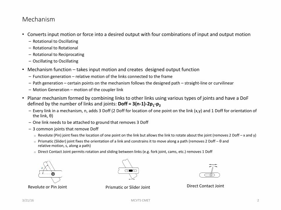
• Planar mechanism formed by combining links to other links using various types of joints and have a DoF defined by the number of links and joints: Doff = 3(n-1)-2p1-p2
– Every link in a mechanism, n, adds 3 Doff (2 Doff for location of one point on the link (x,y) and 1 Doff for orientation of the link, θ)
– One link needs to be attached to ground that removes 3 Doff
– 3 common joints that remove Doff
o Revolute (Pin) joint fixes the location of one point on the link but allows the link to rotate about the joint (removes 2 Doff – x and y)
o Prismatic (Slider) joint fixes the orientation of a link and constrains it to move along a path (removes 2 Doff – θ and relative motion, s, along a path)
o Direct Contact Joint permits rotation and sliding between links (e.g. fork joint, cams, etc.) removes 1 Doff
3/21/16 MCVTS CMET 2
Revolute or Pin Joint Prismatic or Slider Joint Direct Contact Joint

Key Terms
Term Definition
Drive Link Link that provides the input force into the mechanism
Drag or follower Link
Link that provides the output from the mechanism
Coupler Link that connects the drive link to the drag or follower link
Grashof Inequality
Inequality that guarantees that at least three inversions have rotating input link (s+l<p+q)
Inversion Different forms of the same mechanism where different links are grounded. Does not change the relative motion of links to each other but does affect their absolute motion
Toggle or Dead point
Mechanism where the coupler and side link (driver or drag link) are aligned and a torque applied to the side link cannot induce rotation. Represents the extreme position of the drag link
Change Point Position where all links are in-line and the mechanism can flip between the two possible mechanisms without disassembly (equality condition for Grashof equation)
Transmission Angle
Angle between the coupler link and the drag link and determines the force transmitted from the coupler to the drag link. It is maximum when the angle is 90°.

Degrees of Freedom – 2D
• Rigid body defined by location of one point (x,y) and orientation, θ – 3 Doff
• Each rigid adds 3 Doff to the mechanism
• Constraints remove Doff based on how they limit movement
– Grounding a link (fix position and orientation) removes 3 Doff
– Pin joints – Removes 2 Doff (allows movement in θ direction only)
– Slider joint – Removes 2 Doff (allows movement in one direction only)
– Roller joint – Removes 1 Doff (allows movement in one direction and θ)

Mechanism – cont.
• For a four bar linkage relationship of the link lengths determine the allowable input and output motion combinations as defined by Grashof’s law: s+l≤p+q s and l are the shortest and longest links; p and q are the other two links– If the inequality is satisfied then there are three different inversions (Grashof
mechanism)o Crank rocker (drive link rotates 360° and drag link oscillates)
o Double crank (both drive link and drag link rotate 360° )
o Double rocker (neither drive link or drag link can rotate 360° )
– If the inequality is not satisfied then no link can rotate 360° (double rocker for all inversions)
– If the equality holds then it is Grashof mechanism but mechanism could flip to alternate orientation without disassembly when all links are aligned
2/25/2016 MCVTS CMET 5
Grashof Non-Grashof

Grashof Mechanism
• Three basic crank-drag link rotation– Rotation – Oscillating (Crank – Rocker)
– Rotation – Rotation (Crank – Crank)
– Oscillating – Oscillating (Rocker – Rocker)
• Rotation type depends on inversion and Grashof type– Inversion – same linkage with different link attached to ground
• Grashof mechanism identified by relationship between link lengths– At least one inversion will have rotational input and oscillating output
• Links identified by relative lengths– s≤p≤q≤l (s – Shortest; l – Longest; p and q – intermediate lengths)
• Grashof mechanism has s+l≤p+q– s+l<p+q (crank-rocker, or crank-crank depending on inversion)
– s+l=p+q (change point where mechanism switches shape)
ls
pq
DriveLink
Fixed Link
http://ocw.metu.edu.tr/pluginfile.php/3957/mod_resource/content/0/ch7/7-1.htm
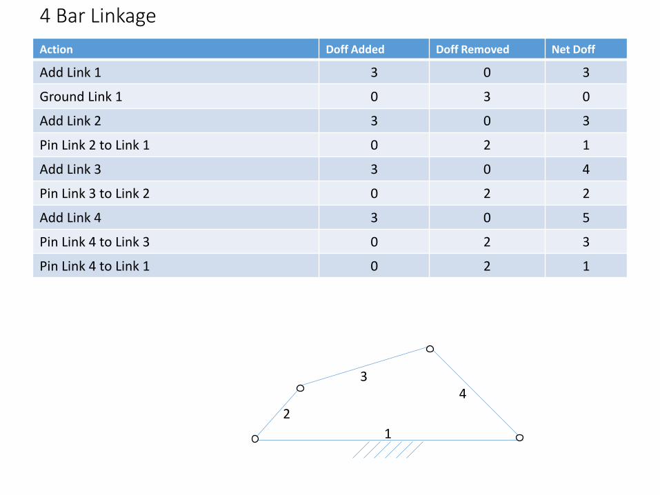
4 Bar Linkage
Action Doff Added Doff Removed Net Doff
Add Link 1 3 0 3
Ground Link 1 0 3 0
Add Link 2 3 0 3
Pin Link 2 to Link 1 0 2 1
Add Link 3 3 0 4
Pin Link 3 to Link 2 0 2 2
Add Link 4 3 0 5
Pin Link 4 to Link 3 0 2 3
Pin Link 4 to Link 1 0 2 1
1
2
34
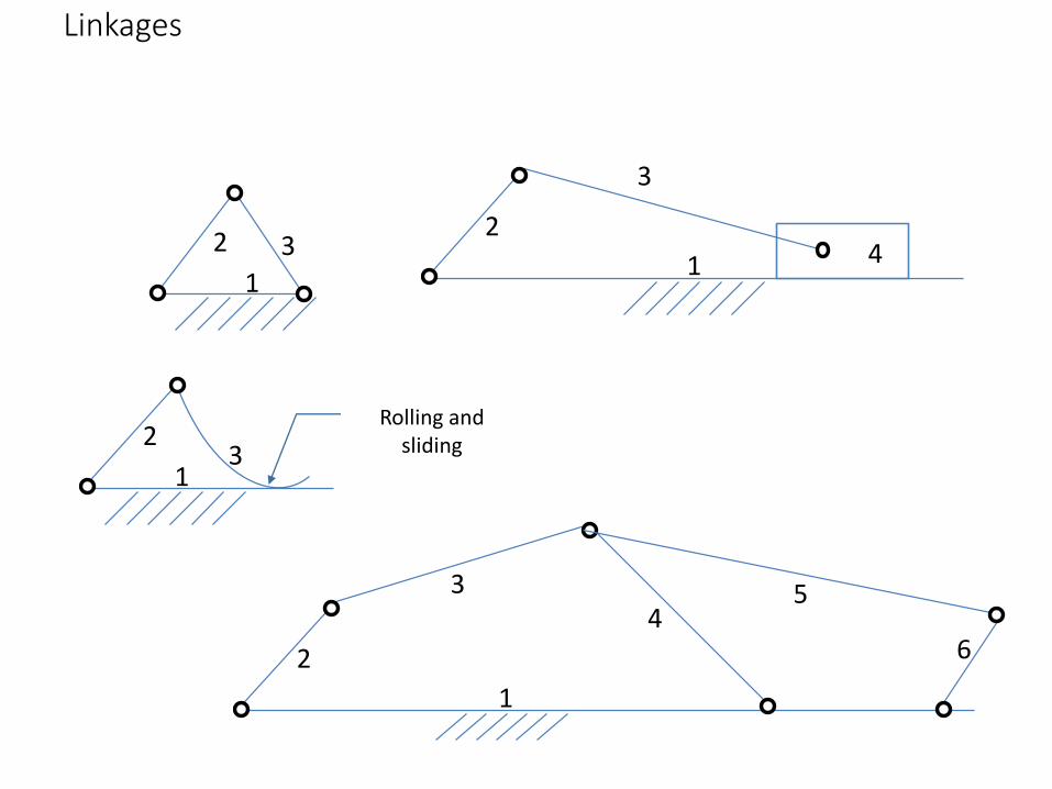
Linkages
1
2 31
2
3
4
1
23
1
2
34
6
5
Rolling and sliding

Work Sheet
Action Doff Added Doff Removed Net Doff
Add Link 1 3 0 3
Ground Link 1 0 3 0
Complete one worksheet for each of 4 mechanisms
1
2 31
2
3
4 1
23
1
2
34
6
5
A B C D
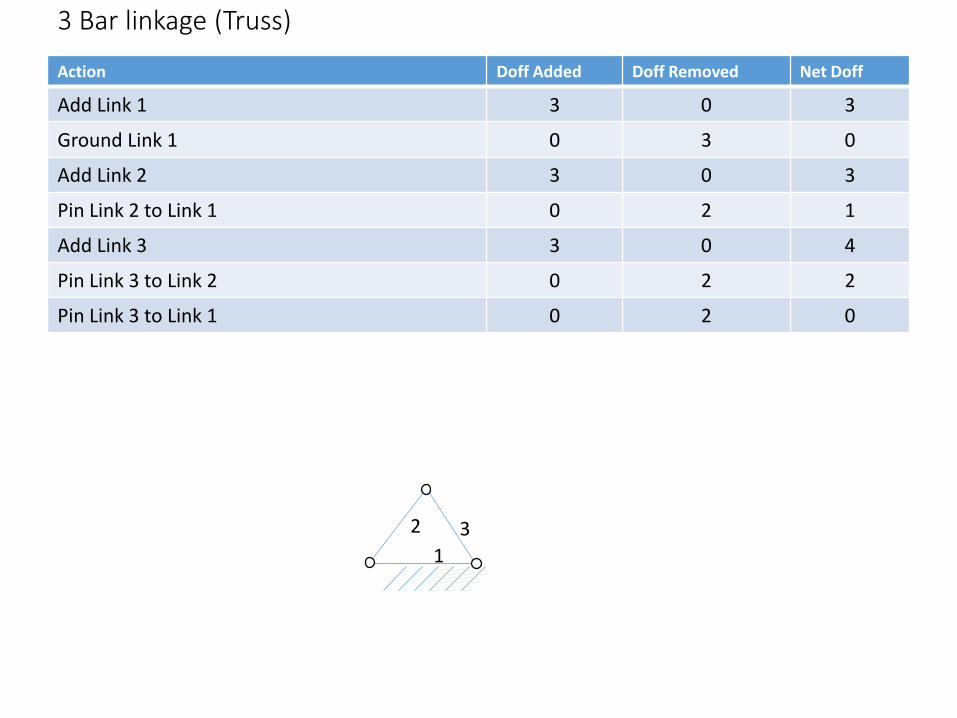
3 Bar linkage (Truss)
Action Doff Added Doff Removed Net Doff
Add Link 1 3 0 3
Ground Link 1 0 3 0
Add Link 2 3 0 3
Pin Link 2 to Link 1 0 2 1
Add Link 3 3 0 4
Pin Link 3 to Link 2 0 2 2
Pin Link 3 to Link 1 0 2 0
1
2 3

Slider Crank
Action Doff Added Doff Removed Net Doff
Add Link 1 3 0 3
Ground Link 1 0 3 0
Add Link 2 3 0 3
Pin Link 2 to Link 1 0 2 1
Add Link 3 3 0 4
Pin Link 3 to Link 2 0 2 2
Add Link 4 3 0 5
Pin Link 4 to Link 3 0 2 3
Constrain Link 4 to Link 1 to slide only 0 2 1
1
2
3
4

3 Bar with Rolling Joint
Action Doff Added Doff Removed Net Doff
Add Link 1 3 0 3
Ground Link 1 0 3 0
Add Link 2 3 0 3
Pin Link 2 to Link 1 0 2 1
Add Link 3 3 0 4
Pin Link 3 to Link 2 0 2 2
Constrain link 3 to link 4 - prevent motion away from link 1 (allow sliding and rolling)
0 1 1
1
23

6 Bar LinkageAction Doff Added Doff Removed Net Doff
Add Link 1 3 0 3
Ground Link 1 0 3 0
Add Link 2 3 0 3
Pin Link 2 to Link 1 0 2 1
Add Link 3 3 0 4
Pin Link 3 to Link 2 0 2 2
Add Link 4 3 0 5
Pin Link 4 to Link 3 0 2 3
Pin Link 4 to Link 1 0 2 1
Add Link 5 and 6 6 0 7
Pin Link 5 to Link 3 and 4 0 2 5
Pin Link 6 to Links 5 and 1 0 4 1
1
2
34
6
5
Note: Adding Pin joint to connect three Links removes 4 Doff – two for each pair

Graphical Position Analysis
• 4 Bar Linkage– Drive link constrained to travel in a circle about the pin joint between the driver link and ground link
– Drag link constrained to travel in a circle about the pin joint between the drag link and the ground link
– One point on the coupler link is tied to the driver link, the opposite point can be tied to the drag link in one of two positions (change point mechanism)
• Crank-Slider– Drive link constrained to travel in a circle about the pin joint between the driver link and ground link
– Slider is constrained to travel along a straight line passing through the pin joint that connects the slider to the coupler link
– One point on the coupler link is tied to the driver link, the opposite point can be tied to the slider along the line passingthe connecting point parallel to the direction of travel in one of two positions (change point mechanism)
• Methodology
– Draw the circled centered on the ground pivot end of the drive link whose diameter is equal to the drive link length to the attachment joint of the coupler link
– For 4-BL draw the circle centered on the ground pivot end of the drive link whose diameter is equal to the drag link length to the attachment joint of the coupler link
– For slider crank draw a line through the joint between the slider and the coupler link an parallel to the line of motion
– Select an orientation of the drive link and draw a circle with radios equal to the coupler length and center on the drive link
– The arc of this coupler link intersection the output circle, or line for slider case in points = one point requires the mechanism to pass through an change point and should not be used
– Draw as many orientations as necessary to get a view of how the mechanism changes over time
• Repeat for any point on the coupler by using the radius to that point from the P23
2/25/2016 MCVTS CMET 14

Velocity Analysis – Instant Centers of velocity
• Do Now – For figure 1 find the velocity of points A, B and C on the link that is attaches to the pivot point, 012
2/25/2016 MCVTS CMET 15
012
A B
C
A
B
C
PointFigure 1 Figure 2
Position rel to xy coord (ft)
Velocity (fps) Position rel to xy coord (ft)
Velocity (fps)
A (0.3,1) ? (0.9, 1.0) 9.220 139.4°
B (1.5, 0.6) ? (0.4, 1.7) 14.04 175.9°
C (1.9,1.9) ? (2.4, 1.3) 23.26 105.5°
ω 15 rad/s N/A Position of 012? ω? Rad/s
Fig. 2Fig. 1

Class Activity – Graphical Velocity Analysis of 4BL
• Pair off into teams
• Each member designs a Grashof mechanism on paper using the method learned last week
– Mechanisms don’t need to be the same just be sure it fits on a single page
– Bigger paper is available for analysis
• The coupler link should be a triangular link with the hypotenuse between the attachment points connected to the drive and follower link
– Triangle is a 3-4-5 triangle
– Scale the other sides from the hypotenuse
– The point at the 90° is point P
• Select a rotation speed and angle for the drive link.
• Swap papers and calculate following information using the graphical method
– ω3
– ω4
– V23, V34, VP
2/25/2016 MCVTS CMET 16

Instant Centers
• Every link moves relative to every other link
• Every pair of joints has a common point P about which both links rotate - called Instant Centers of Velocity
– Point may be fixed or “moving” but is considered stationary at that instant
– Pj,k=Pk,j
– NP=n(n-1)/2 where NP – the number of centers of velocity, n – the number of links
– 4 BL: NP=4(4-1)/2=6
• Continuity requires that the common ends of the links have the same velocity
• Identification of Instant Centers
– One set of instant centers are at the joints between adjoining links
– Arnhold-Kennnedy Theorem identifies the remaining instant centers
o The three instant centers (Pij, Pjk, Pik) that are shared by three links (I, j, k) are collinear
o Identify two pair of instant centers and an additional Instant Centers can be located at the intersection
2/25/2016 MCVTS CMET 17
2
3
4P23
P34
P14P12
P24
P13
P23
P34
P14P12
2
3
4

Finding Velocities with Instant Centers
• Angular velocity (rad/s) of each link and linear velocity (fps or mps) of any point on the mechanism can be found using Instant Centers
– Instant centers that include the ground link, P1j, have zero linear velocity
– Every point on link j rotates about this point
– Instant centers shared by adjoining movable links has the same linear velocity in the same direction
– Direction of rotation take by inspection of how the links need to rotate to maintain velocity continuity
2/25/2016 MCVTS CMET 18
P23
P34
P14P12
P24
P13
2
3
4
Given:L2=0.55L3=1.84L4=1.64L1=0.75ω2=+2rad/s
Measured from figureL23/13=1.78L34/13=2.71
Find ω4
Find velocity of P23
P23 is on links 2 and 3V23= ω2(0.55)=1.10fps
Find ω3
V23= ω3(1.78)=1.10ω3=0.618rad/sec (Direction by inspection)
Find V34
P34 is on links 3 and 4V34 = ω3(2.71)=1.67fps
Find ω4
V34 = ω4(1.64)=1.67fpsω4=1.06fps
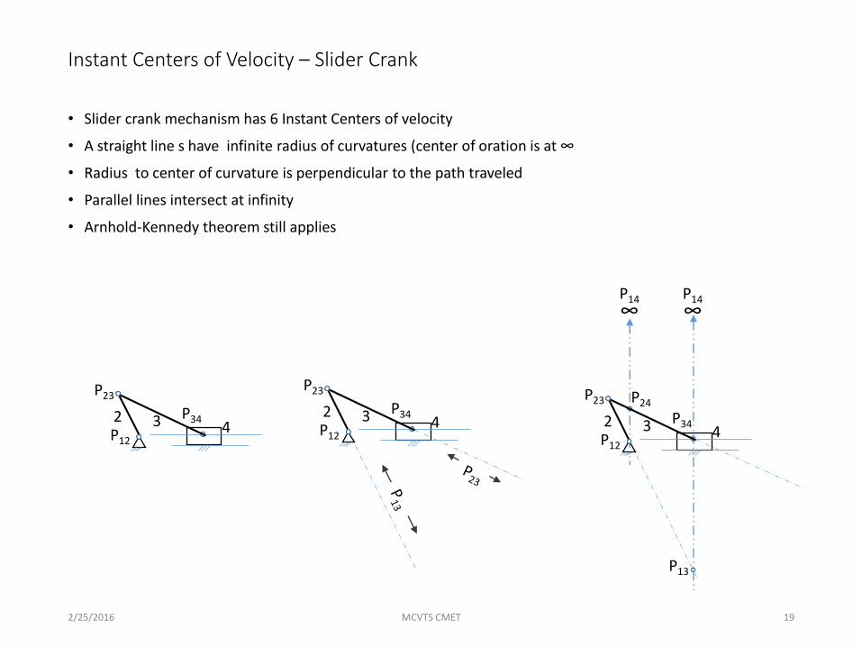
Instant Centers of Velocity – Slider Crank
• Slider crank mechanism has 6 Instant Centers of velocity
• A straight line s have infinite radius of curvatures (center of oration is at ∞
• Radius to center of curvature is perpendicular to the path traveled
• Parallel lines intersect at infinity
• Arnhold-Kennedy theorem still applies
2/25/2016 MCVTS CMET 19
P23
P34
P12
P24
P13
2 3 4
P14
∞P14
∞
P23
P34
P12
2 3 4
P23
P34
P12
2 3 4

Instant Centers of Velocity – Special Cases
• Parallel links in 4BL
– V13 is at infinity from the parallel links
– Link 3 has no rotational velocity only translational velocity
– V23= V34=ω2r2=ω4r4
2/25/2016 MCVTS CMET
2
4
3
P13
∞
P13
∞
P12
P23
P34
P14
2
4
3

Graphical Analysis – Velocity
Graphical method works on the assumption that a the absolute velocity of point that is in common between two links is the same (continuity requires this to prevent the mechanism from tearing itself apart)
• Label instant centers of velocity of physically joined links – Links that share a common pin joint
– Links that are constrained to move along a curved path have an instant center of rotation that is perpendicular to the tangential path at the current instant and located at the center point of the curvature
– Links that are constrained to move in a straight line have an instant center of rotation at infinity on a line that is perpendicular to the motion of travel – all points on the link have the same velocity vector
– Parallel lines intersect at infinity so that a parallel line can be constructed through a different point
3/21/16 MCVTS CMET 21
P23
P34
P14P12
2
3
4
1
P23
P34
P12
2 3 4
P14
∞
P14
∞
P14
∞
P14
∞
2
4
3
P13
∞
P13
∞
P12
P23
P34
P14

Identifying remaining Instant Centers of Velocity
• Use Arnhold-Kennedy Theorem to identify the remaining instant centers– Two points that share a common link in their pair (V12 and V23) will have the third combination (V13)
on the line that defined by the first pair of points)
– Actual location will be the intersection of two lines that pass through two pair of points that have the same common combination
3/21/16 MCVTS CMET 22
P23
P34
P14P12
2
3
4
1
P23
P34
P12
2 3 4
P14
∞
P14
∞
P14
∞
P14
∞
2
4
3
P13
∞
P13
∞
P12
P23
P34
P14
P24
P13
P24
P13
P24

Calculating Velocity
• Velocity is calculate for each posting of the mechanism
– For continuous equation use the loop equation for velocity
• Velocity of a point Vij is the same whether it is on link i or link j and have the units of distance/sec
• If one of the links is the ground link, then the point has 0 translational velocity and the moving link rotates about this point and does not translate - Units of the rotating link angular velocity are rad/sec
3/21/16 MCVTS CMET 23
P23
P34
P14P12
2
3
4
1
P24
P13
Methodology for given position and input velocity (ω2)
• Translational Velocity of P24
VP24=ω2r2= ω3r13|23 Units: Dist./sec• Angular Velocity of link 3
ω3=𝑉𝑃24
𝑟12|23Units: rad/sec
• Translational velocity of VP24
VP24 = ω2r12|24 =ω4r14|24 Units: Dist./sec• Translational velocity of VP34
VP34 = ω3r13|34 =ω4r14|34 Units: Dist./sec• Angular Velocity of link 4
ω4=𝑉𝑃34
𝑟14|34=
𝑉𝑃24
𝑟14|24Units: rad/sec
New

Mechanism Synthesis
• Mechanism Analysis
– Given: Link Lengths, Link Quantity, Driver Link position, Driver Link Velocity and Acceleration
– Find: Link velocity, Position and Orientation
• Mechanism Synthesis – Design a mechanism to generate a desired output
– Type: What kind of mechanism is needed (Linkage, cam, gear or combination)
– Number: How many links and joints needed to obtain the specified path
– Dimension: How big the mechanism
• Types of design requirements
– Function Generation – Output member rotates, oscillates or reciprocates according to a specified function of time or function of the input motion
– Path Generation – Coupler point generates a path having a prescribed shape
– Body Guidance – Moving an object from one position to another through any combination of Rotation and Translation
2/25/2016 MCVTS CMET 24

Synthesis
• Path generation: 2 – 3 precision points– Select up to 3 Precision points on the path that through which a point on the coupler
must pass. Higher number of precision points requires alternate method
– Specify the shape of the coupler linko Length of the portion that connects drive link to the drag link, r3
o Location, rP and orientation ,φ, of the fixed location of point, P
– Record the position of the pin joint V23 and V24 for each location and position of link 3 for the three positions of Point P
– For three precision points the ground pins for the drive and drag links are the intersection of the appropriate perpendicular bisectors of the plotted pin joints, V23 and V24
– For two precision points you may also select the link lengths of the drive and drag links
– Check the mechanism to see that if satisfies the requirementso Grashof inequality
o Acceptable path generated outside of the precision points
o Acceptable motion of the mechanism – no change points required
– If unacceptable then choose different shape for link 3 and repeat the procedure
2/25/2016 MCVTS CMET 25
φ
P
V34
V23

Synthesis – Rapid Return
• 4 Bar linkage can have different extension and retraction rates for the output link, drag link or slider, with a constant velocity input;
• Extreme position of the output link occurs when the drive link and coupler link are aligned
–α – Input angle to extend
–β – Input angle to retract
–δ – Construction angle subtended by the alignment of the coupler and drive link in the extreme positions (toggle point)
𝛿 = 180° − 𝛼 = 180° − 𝛽
–Θ4 – Angle subtended by output link in the extreme position
3/21/16 MCVTS CMET 26
α+β=360° and Timing Ratio: 𝑇𝑅 =𝛼
𝛽
New
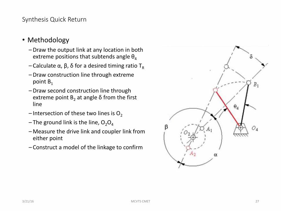
Synthesis Quick Return
• Methodology– Draw the output link at any location in both
extreme positions that subtends angle θ4
– Calculate α, β, δ for a desired timing ratio TR
– Draw construction line through extreme point B1
– Draw second construction line through extreme point B2 at angle δ from the first line
– Intersection of these two lines is O2
– The ground link is the line, O2O4
– Measure the drive link and coupler link from either point
– Construct a model of the linkage to confirm
3/21/16 MCVTS CMET 27

Quick Return
Synthesze a mechanism with a time ratio of 1:1.25 with 45° output rocker motion
1) Draw rocker in the extreme position at any location
2) Calculate α, β, δ
a) TR =α
β, δ=180°-α=β-180°
b) α=160°, β=200°, δ=20°
3) Draw construction line through B1 and copy second construction line through B2 at angle δ to construction line through B1
4) Intersection of the two lines is the pivot point for the drive link
5) Crank link length calculated by measuring P12B1 and P12B2
a) r2+r3= P12B1
b) r3-r2= P12B2
6) Calculate Grashof condition and suitability of the mechanism, Select alternate items if mechanism is unsatisfactory
a) Follower link length and orientation so that P12 is further from P14
3/21/16 MCVTS CMET 28
P14
B1
B2
45°
δ
Method is valid for time ratios down to about 1:1.5 to maintain acceptable transmission angle
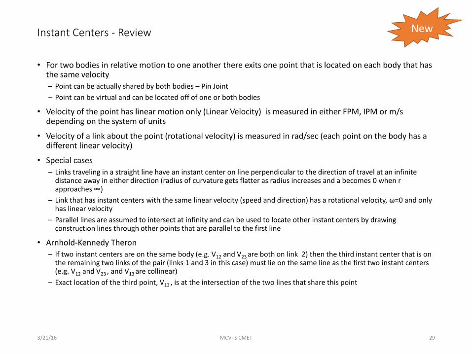
Instant Centers - Review
• For two bodies in relative motion to one another there exits one point that is located on each body that has the same velocity
– Point can be actually shared by both bodies – Pin Joint
– Point can be virtual and can be located off of one or both bodies
• Velocity of the point has linear motion only (Linear Velocity) is measured in either FPM, IPM or m/s depending on the system of units
• Velocity of a link about the point (rotational velocity) is measured in rad/sec (each point on the body has a different linear velocity)
• Special cases
– Links traveling in a straight line have an instant center on line perpendicular to the direction of travel at an infinite distance away in either direction (radius of curvature gets flatter as radius increases and a becomes 0 when r approaches ∞)
– Link that has instant centers with the same linear velocity (speed and direction) has a rotational velocity, ω=0 and only has linear velocity
– Parallel lines are assumed to intersect at infinity and can be used to locate other instant centers by drawing construction lines through other points that are parallel to the first line
• Arnhold-Kennedy Theron
– If two instant centers are on the same body (e.g. V12 and V23 are both on link 2) then the third instant center that is on the remaining two links of the pair (links 1 and 3 in this case) must lie on the same line as the first two instant centers (e.g. V12 and V23 , and V13 are collinear)
– Exact location of the third point, V13 , is at the intersection of the two lines that share this point
3/21/16 MCVTS CMET 29
New