mechanics and mechanical engineering - tulkdm.p.lodz.pl/articles/2013/17_3_1_j_n.pdf · mechanics...
TRANSCRIPT
Mechanics and Mechanical EngineeringVol. 17, No. 3 (2013) 225–234c⃝ Lodz University of Technology
Modeling Lamellar Cracks
Mieczys law Jaroniek
Department of Strength of Materials Lodz University of Technology
Stefanowskiego 1/15, 90–924 Lodz, Poland
Tadeusz Niezgodzinski
Department of Dynamics Lodz University of Technology
Stefanowskiego 1/15, 90–924 Lodz, Poland
Received (10 March 2013)Revised (16 May 2013)
Accepted (20 July 2013)
In this work, studies of models simulating lamellar cracks were conducted. These cracksare formed in rolled sheets with non-metallic inclusions. Studies of lamellar cracks beganin the 1960s, but there is still no satisfactory theory explaining their formation.
In this work, the application of modeling of samples with non-metallic inclusions forthe study of lamellar cracking has been presented. Studies were conducted using tworesearch methods: the photoelastic method and the finite element method.
The possibility of crack formation was analyzed in models generated from imagesobtained from metallographic specimens.
Keywords: Non–metallic inclusions, photoelastic tests, finite element method, lamellarcracking
1. Method of modeling lamellar cracks
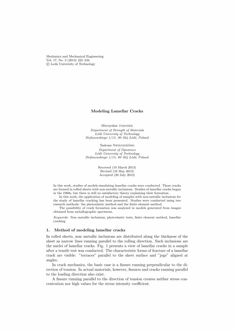
In rolled sheets, non–metallic inclusions are distributed along the thickness of thesheet as narrow lines running parallel to the rolling direction. Such inclusions arethe nuclei of lamellar cracks. Fig. 1 presents a view of lamellar cracks in a sampleafter a tensile test was conducted. The characteristic forms of fracture of a lamellarcrack are visible: ”terraces” parallel to the sheet surface and ”jogs” aligned atangles.
In crack mechanics, the basic case is a fissure running perpendicular to the di-rection of tension. In actual materials, however, fissures and cracks running parallelto the loading direction also exist.
A fissure running parallel to the direction of tension creates neither stress con-centration nor high values for the stress intensity coefficient.
226 Jaroniek, M, Niezgodzinski, T.
In a sample subjected to uniform tension with a fissure aligned at an angle of βto
the direction of tension, the values of stress intensity coefficients are equal to[3]:
• for loading method I (tearing of the fissure vertex)
KI = σext
√πa sin2 β (1)
• for loading method II (coplanar shearing)
KII = σext
√πa sinβ cosβ (2)
where:σext – external tension stress valuea – half of the fissure length.For a fissure parallel to the direction of tension, β = 0, and so KI = KII = 0.These relationships are obvious for fissures and cracks with thicknesses approach-
ing zero, but in cases where crack nuclei are caused by non-metallic inclusions, whichhave the nature of fissures of a specific thickness and shape after sheet rolling, thena mixed mode of cracking can occur at the ends of such fissures (caused by non–metallic inclusions).
Figure 1 View of lamellar cracks after tearing of the sample

Modeling Lamellar Cracks 227
Non–metallic inclusions have significantly lower strength and elasticity (Young’smodulus) than ferritic–pearlitic steel, in this case. Such inclusions may have thenature of voids and can become crack nuclei.
Samples were made with a fissure in the center of the sample and with fissuresin a system similar to the actual arrangement of inclusions obtained on the basisof a metallographic specimen. Studies were conducted using two research methods:the photoelastic method and the finite element method.
The studied samples were placed in a polariscope and subjected to uniformtension or bending. The images of obtained isochromatic lines are shown on thefigures. The results of these studies were compared with numerical calculations.
2. Models simulating lamellar cracks
Figure 2 shows an exemplary metallographic specimen of pearlitic–ferritic steel sheetwith non–metallic inclusions in the form of manganese sulfides MnS and aluminatesAl2O3. This is a typical image of a sheet in which lamellar cracks may form. Narrowsulfide bands can be seen in the middle of the photograph.
Figure 2 View of metallographic specimen of a sheet with inclusions
Based on typical metallographic specimens of steel sheets, two types of distributionsof artificial fissures were accepted for study. These distributions are shown in Fig. 3.A central fissure and a symmetrical system of four inclusions (voids) were selectedfor study.
3. Photoelastic studies
Models were made from typical epoxide resin (EP 52). Their properties and themethod of their determination were given in work [4].
The placement of artificial fissures in the model was similar to the arrangementof actual inclusions observed in views of metallographic specimens of sheets obtainedfrom scrapped overhead crane girders.

228 Jaroniek, M, Niezgodzinski, T.
a)
b)
Figure 3 a) Model with one central fissure, b) Model with four fissures
The studied samples were placed in a polariscope and subjected to uniform tensionor pure bending; isochromatic images were obtained. Studies were conducted usingwhite light or monochromatic sodium light, with linear and circular polarization.Thus, total or partial isochromatic lines were obtained.
Photoelastic studies were conducted by increasing the load and analyzing thestress state after each such increase (based on isochromatic line distribution) soas to determine the influence of voids on changes in stress fields and their mutualinteraction upon the areas surrounding voids or fissures.
Fig. 4 presents an image of a model with a central fissure during an axial tensiletest. Monochromatic light was applied: yellow sodium light. Total isochromaticlines are visible (polarizer perpendicular to analyzer) in circularly polarized light.Fig. 5 presents an analogous image of partial isochromatic lines in circularly polar-ized white light (polarizer paralell to analyzer).
Small concentrations of stress are visible on both ends of the fissure subjectedto tension.
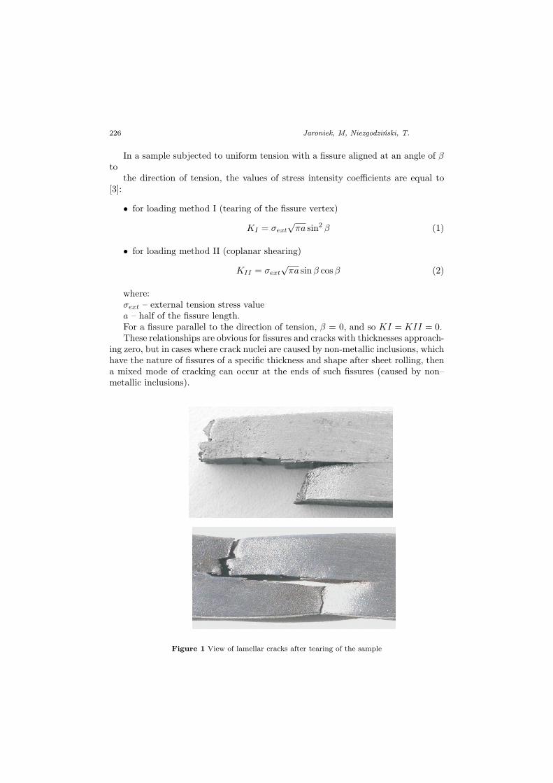
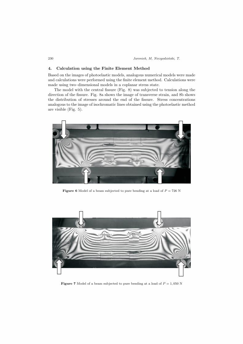
The model with four fissures was subjected to a bending load as a beam bent atfour points. Images of isochromatic lines in white light for a load of P = 726 N arepresented in figure 6, and the same sample in sodium light for a load of P = 1, 050N can be seen in the next figure. Stress concentrations can be observed only at theends of compressed fissures.

Modeling Lamellar Cracks 229
Figure 4 Photograph of isochromatic lines in sodium light
Figure 5 Photograph of isochromatic lines in white light
230 Jaroniek, M, Niezgodzinski, T.
4. Calculation using the Finite Element Method
Based on the images of photoelastic models, analogous numerical models were madeand calculations were performed using the finite element method. Calculations weremade using two–dimensional models in a coplanar stress state.
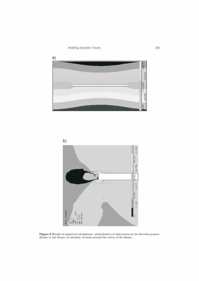
The model with the central fissure (Fig. 8) was subjected to tension along thedirection of the fissure. Fig. 8a shows the image of transverse strain, and 8b showsthe distribution of stresses around the end of the fissure. Stress concentrationsanalogous to the image of isochromatic lines obtained using the photoelastic methodare visible (Fig. 5).
Figure 6 Model of a beam subjected to pure bending at a load of P = 726 N
Figure 7 Model of a beam subjected to pure bending at a load of P = 1, 050 N
Modeling Lamellar Cracks 231
a)
b)
Figure 8 Results of numerical calculations: a)distribution of dislocations in the direction perpen-dicular to the fissure, b) intensity of stress around the vertex of the fissure

232 Jaroniek, M, Niezgodzinski, T.
Figure 9 Model of a beam subjected to pure bending at a load of P = 1, 050 N. Reduced stressdistribution according to Huber’s hypothesis
Figure 10 Model of a beam subjected to pure bending at a load of P = 1, 050 N. Distribution ofnormal stresses σx
The models with four fissures were subjected to pure bending. Images of stressdistributions are presented in Figs 9 and 10. Small stress concentrations are visiblearound the fissures only in the compressed area.
Fissures were modeled in the shape of narrow rectangles. Due to the variousshapes of inclusions present in specimens, modeling of fissures in the shape of par-allelograms was also performed. Results are presented in Fig. 11, and in this case,stress concentrations were significantly reduced.

Modeling Lamellar Cracks 233
A
A
Figure 11 Model of bent beam – magnification of the fissure area: a) Normal stress σx distributionalong cross–section A – A, b) Normal stress σx distribution along cross–section A – A
Figure 12 Results of experimental studies with the application of the photoelastic method
234 Jaroniek, M, Niezgodzinski, T.
5. Conclusions
Two research methods were used for these studies: the photoelastic method andthe finite element method. These two methods supplement each other very well.Results obtained using each of these methods can be easily compared. This isespecially clear in the case of the image of isochromatic lines of the entire studiedfield, which is obtained from experimental studies using the photoelastic method.An analogous isochromatic line image is obtained using the numerical method, asa field of principal stress differences.
The photoelastic method can also be used to validate the numerical model madeon the basis of the finite element method.
The potential for the joining of non–metallic inclusions, voids, and initial crackswas studied in the direction parallel to the exterior surface of the sheet (so–called”terraces” are formed) and at an angle (so–called ”jogs” are formed); this leads tothe formation of lamellar cracks.
In further works, other arrangements of inclusions and cracks, as well as theirdevelopment under fatigue loading conditions, will be examined.
This work has been financed by funds from the National Science Centre, projectno. 7151/B/T02/2011/40
References
[1] Blum, A. and Niezgodzinski, T.: Pekniecia lamelarne, Wydawnictwo InstytutuTechnologii Eksploatacji – Monografie, Radom, 2007.
[2] Niezgodzinski, T. and Kubiak, T.: Uber den Bruch von geschweißten Stahlblechen– Lamellenbruche, VDI Berichte, 1757, 11–18, 2003.
[3] Neimitz, A.: Mechanika Pekania, PWN, Warsaw, 1998.
[4] Jaroniek, M. and Niezgodzinski, T.: Application of photoelasticity for study oflamellar cracks,Materials of the XXIV Symposium on Fatigue and Cracking Mechanics,Bydgoszcz, 2012.