mechanical pressure gauges 101 - lesman · mechanical pressure gauges 101 . 2 today’s agenda . 3...
TRANSCRIPT

1
Mechanical Pressure Gauges 101

2
Today’s
Agenda

3
Importance of Mechanical Gauges
Why Maintain Them?

Importance of Mechanical Gauges
Why Maintain Them?
• Provide a local pressure indication
• Predict how long a piece of
equipment can be safely
and economically run
• Identify potential loss of process or loss of containment
• Diagnose causes of system
and production disruptions
• Detect signs of degradation in process performance not otherwise tracked
through DCS equipment

5
Pressure Gauges:
Sole Source of Data
Discharge pressure
Suction pressure
Differential pressure
Mechanical seal flush
pressure
Steam quench
pressure

6
Pressure Gauges:
Calculating Risks
Pumps rank
in failure incidents and
maintenance costs. And,
repairs account for
of life cycle costs.
27%
1st
Source: Pump User’s Handbook

7
The Pressure Gauge:
Current State
At least
of pressure gauges require
immediate replacement. And,
and additional
need corrective action.
40%
25%

8
Gauge Design & Basic Principles
Gauge Design Review
9
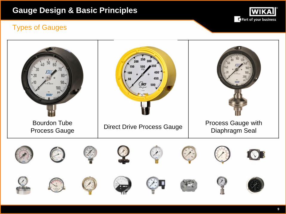
Gauge Design & Basic Principles
Types of Gauges
Bourdon Tube
Process Gauge Direct Drive Process Gauge
Process Gauge with
Diaphragm Seal

10
Gauge Design & Basic Principles
Gauge Components
Measuring element
(Bourdon tube) End piece
of the tube
Pull Rod
(linkage)
Movement
Pointer
Dial
Pressure
Pressure connection

11
Gauge Design & Basic Principles
Process Gauge
Excellent load-cycle stability and shock resistance
Standard 0.6 mm restrictor
NEMA 4X/IP65 weather tight case
Standard overload stop
Liquid fillable
Safety case design
Specifically designed for the chemical and petrochemical processing industries
Suitable for corrosive environments and gaseous or liquid media that will not
obstruct the pressure system
Process Gauge

12
Gauge Design & Basic Principles
A Direct Drive is ideal for heavy mechanical vibration
Designed for high dynamic pulsation, vibration and
shock
Tube made of Inconel X-750 alloy, highly resistant to
temperature extremes with excellent oxidation and
corrosion properties
No delicate internal movement
No gears, linkages or springs to wear or break
Safety case design
Direct Drive Gauge

13
Gauge Design & Basic Principles
A diaphragm seal is ideal for severe
duty applications
Pressure spikes
Pulsation
High temperatures
Corrosive media
Suspended solids
Highly viscous, crystallizing or clogging
media
Acts as a chemical barrier and/or
thermal barrier
Diaphragm Seal

14
Problematic Operating Conditions
Gauge Failures & Solutions

15
Overpressure Mechanical Vibration Pulsation Spikes
Temperature
Gauge Failure
The most common gauge failures (in order of criticality)
Most Common Gauge Failures
Corrosion Clogging Mishandling and
Improper Use

16
Pressure Spikes
Indicators
• Bent, broken, fish-hooked pointer
• Knicked pointer (hitting stop pin)
Root Cause/Effects
• Abrupt increase/decrease in pressure
• Often caused by pump on/off or valve
open/close
• Bourdon tube rupture & media release
Problematic Operating Conditions & Solutions
Risk: Bourdon Tube Rupture

17
Overpressure/High Pressure
Indicators
• Operating near or past
maximum pressure
• Pointer pegged against stop pin
Root Cause/Effects
• Using incorrect pressure range
• Bourdon tube rupture & media
release
Problematic Operating Conditions & Solutions
Risk: Bourdon Tube Rupture
Pictures from actual gauge failures

18
Problematic Operating Conditions & Solutions
Solutions/Recommendations
Investigate
• Appropriate pressure range?
• External factors?
Model – Process Gauge
• Overload stop standard
• Liquid case fill to reduce internal wear
• Extreme cases – Diaphragm seal with internal super restrictor (0.3 mm)
Accessories
• Snubber
• Overpressure protector
Risk: Bourdon Tube Rupture
Best Practice: 2X normal operating pressure

19
Pulsation
Indicators
• Pointer flutter
Root Cause/Effects
• Media rapidly cycling through pressure system
• Dynamic (cyclic) loading wears movement
components down
Problematic Operating Conditions & Solutions
Risk: Bourdon Tube Fatigue
Video recorded in the field

20
Pulsation
Root Cause/Effects
• Movement no longer anchors Bourdon tube
• Thin wall of Bourdon tube fatigues and cracks
• Media release
Problematic Operating Conditions & Solutions
Risk: Bourdon Tube Fatigue
Worn Segment Gear Worn Pinion Gear
Elliptical Form
Bourdon Tube Crack
Picture from actual gauge failures

21
Vibration
Indicators
• Missing pointer
• Black dust on dial
• Scrapes on dial from loose pointer
• Missing window, window ring or back plate
Root Cause/Effects
• Misaligned pumps
• Reciprocating compressors
• Poor fixture mount
Problematic Operating Conditions & Solutions
Risk: Bourdon Tube Fatigue

22
Vibration
Root Cause/Effects
• Vibration breaks movement
• Movement no longer anchors Bourdon tube
• Thin wall of Bourdon tube fatigues and cracks
• Media release
Problematic Operating Conditions & Solutions
Risk: Bourdon Tube Fatigue
Pictures from actual gauge failures

23
Problematic Operating Conditions & Solutions
Solutions/Recommendations
Investigate
• Determine root cause of vibration
• Other equipment in disrepair?
Model – Process Gauge
• Liquid case fill
– Reduce internal wear
– Lubricates and cools moving parts
– Dampens the effects of vibration
• Extreme cases of pulsation: Snubber or diaphragm seal with internal restrictor
Model – Direct Drive Gauge
• Made to withstand significant shock
• No internal movement
– Direct connection between pressure system and pointer
Risk: Bourdon Tube Fatigue

24
Corrosion (Ambient)
Indicators
• Corroded dial or pointer
• Build-up in case
• Fogged window
• Discolored liquid case fill
Root Cause/Effects
• Contaminants getting inside the case
• Missing fill plug
• Cracked case or window
• Corrosion of the Bourdon tube - media release
Problematic Operating Conditions & Solutions
Risk: Material Deterioration

25
Temperature (Media & Ambient)
Indicators
• Breakdown of gauge components (window, dial
and associated elastomers)
• Discolored dial or liquid case fill
Root Cause/Effects
• Incorrect mounting
• Incorrect accessories
• Elevated temperature stresses the pressure
system
• Media release
Problematic Operating Conditions & Solutions
Risk: Material Deterioration

26
Problematic Operating Conditions & Solutions
Solutions/Recommendations
Investigate
• Determine cause of ambient corrosion or source of high temperature
Model – Process Gauge
• Hermetically sealed pressure gauge (weather protection IP65/NEMA 4X)
• Liquid case fill
– Insulates and protects internal components
– Extreme cases – Diaphragm seal for media temperatures over 212F
Accessories
• Mini-siphon
Risk: Material Deterioration

27
Clogging
Indicators
• Gauge shows no pressure when system is
operating
Root Cause/Effects
• Media that is highly viscous, crystallizing,
hardens, or contains particles or solids that can
clog the socket orifice
• Inoperable gauge
• Shows no pressure
Problematic Operating Conditions & Solutions
Risk: Loss of Functionality

28
General Maintenance/Mishandling & Abuse
Indicators
• Cracked, broken or missing windows
• Leaking case fill
• Missing back plates or fill plugs
Root Cause/Effects
• Old or neglected gauges
• Accelerated degradation and corrosion of the
internal components
Problematic Operating Conditions & Solutions
Risk: Loss of Functionality

29
Problematic Operating Conditions & Solutions
Solutions/Recommendations
Investigate
• Implement maintenance plan
– Inspect gauges on a routine
basis
• Determine if gauge should be on
diaphragm seal to address clogging
Model – Process Gauge
• Designed to be easily serviced in the
field
• Various spare parts available to
address minor issues
Risk: Loss of Functionality

30
Problematic Operating Conditions & Solutions
SS Gauge Tags
Mark each gauge with a stock number
Ensures correct gauge replacement
Mini-Siphon
Water hammer (pressure spike) & high temperature (media)
Small form factor reduces gauge whip
Over-Pressure Protector
Snubber
Individual Gauge Components
Accessories

31
Industry Trends
Current state & Path Forward

32
Industry Trends
Plants have unnecessary complexity from
proliferation of configurations
Simplify configurations to reduce guesswork for
operators and installers
• Manufacturer, gauge type and model, pressure
range, wetted materials, etc.
Develop an effective storeroom inventory that
will:
• Maximize field coverage
• Minimize complexity of configurations
• Eliminate redundant, obsolete or wasted inventory
Complexity of Configurations
Average Reduction in Unique
Gauge Configurations*
Eliminate Duplicate
Configurations
Reduce Make/Model Complexity
Standardize on Common
Pressure Ranges
* Averages from WIKA FAST Instrument Audits

33
How did we get here?

34
Aging Infrastructure

35
Source: Cambridge Energy Research Associates
More than 40% of all
oil and gas professionals
will retire in the next
10 years.

36
AGING
INFRASTRUCTURE
Missing documentation
Processes change, specs outdated
RETIRING EXPERTS
“BRAIN DRAIN”
Doing more with
less experience
UNDER
INVESTMENT
Don’t know what is failing
or what to do about it
Compounding the Issue of Instrument Failure

Improving Reliability &
Total Operating Costs
RESULT Eliminate
misapplications and repeat failures
OBJECTIVE Reduce complexity and
standardize
RESULT Improve reliability with configurations that can
handle operating conditions
OBJECTIVE Specify correct configurations
for process conditions
RESULT Provide functional gauges for trouble-
shooting, PdM capabilities
OBJECTIVE Prevent expensive, essential
equipment failure

38
FAST Services
Offerings & Benefits

39
