mechanical design and analysis of …mgijournal.com/pdf/current_issue_april/3.pdf · mechanical...
TRANSCRIPT

MECHANICALDESIGNANDANALYSISOFPROTOTYPALWAVEENERGYHARNESSERSYSTEM
Increasing concern over the threat of global climate change has led to tremendous research and development of renewable energy. Ocean waves are a huge storage of energy and have considerable potential for mining energy. Research in the area of ocean energy conversion, wave energy, tidal and wind energy has resulted into encouraging technology and in some cases, commercial development too. There is a lack of merging on the best method of extracting energy from the waves and, although earlier invention has usually focused on the concept and design of the primary device, questions arise concerning optimization of power extraction and stabilization. This calls for an efficient technique for harnessing wave energy by employing an electromechanical setup for extracting wave energy and stabilizing the output power. This paper presents a design and construction of an innovative wave energy conversion device to have a solution for an increasing energy demand. It also includes an investigation and study to find various existing wave energy harnessing technologies.
Keywords: Renewable energy, Electromechanical, Energy conversion, Extraction.
1. Introduction
Abstract
1 2P. K. Upadhyay and Md. Towhidul Islam1Assistant Professor, Department of Electrical & Electronics Engineering, BIT Offshore Campus, UAE
2Student, Department of Electrical & Electronics Engineering, BIT Offshore Campus, UAE
1{E-mail: [email protected]}
Ocean which is massive and dominant in its nature, stores tremendous energy in the form of waves, heat, currents and tides to meet entire international demand for power many times over [1]. There are challenges that are faced during the development of ocean Energy technology. Ocean energy companies comprise only an infinitesimal fraction of worldwide energy supply. Due to widespread concern over the world climatic change and environmental impacts on fossil fuels led to increased development in the field of renewable energy. If global obligation to renewables escalates in the nearby future, serious procedures will be implemented to increase the focus on the massive stores of energy in waves. Amplified research and development of renewable sources energy from the waves may be essential for a wide-ranging, complete, and liable energy plan. Research works in this fields suggest that renewable energy from the ocean would most likely improve the environment by substituting fossil fuel plants and dropping carbon emissions. It will be disparagingly significant to guarantee that the progression of new wave energy machineries does not harm the marine atmosphere, which is now topic to
multiple intimidations such as pollution, overfishing, habitat loss, and climate change. This paper discusses and equates major potential sources of renewable energy from the ocean with an understanding toward developing responsible development guidelines for defensing the marine atmosphere as well. Substantial prospects and profits have been identified in the area of ocean wave energy extraction, i.e. harnessing the movement of the sea waves, and changing that motion into electrical energy. In actuality, wave energy is focused form of solar energy in that it is the uneven heating of the Earth's surface that generates the winds, and it is the wind that creates the waves. With the west to east traveling global winds, it is the west shores of land multitudes that realizes the highest wave energy potential, and those potentials escalates towards the Earth's poles. Ocean waves have several rewards over other forms of inexhaustible energy such as wind and solar, in that the waves are more accessible (seasonal, but more constant) and more predictable with better demands. [2].
Vol. 01, Issue 02, April 201684
Journal of Research in Engineering and Applied Sciences
Waves offer significant advantages over other methods when it is used as a renewable source of energy. Sea waves give the maximum energy concentration among inexhaustible energy sources [3]. Waves are produced by winds, which in turn are engendered by solar energy. Solar energy has a strength of 0.1– 0.3
2kW/m on the horizontal surface, which is then converted to an normal power flow intensity of
22–3 kW/m on vertical plane perpendicular to the direction of wave flow just beneath the water surface [4]. Inadequate negative environmental influence in use. Thrope [5] specifies the possible effect and shows an approximation of the life cycle productions of a typical on shore device. In general, offshore devices have the lowest potential impact. Seasonal variation in wave energy is followed by the electricity demand in temperate climates [3].Waves can travel great distances with slight energy loss. As in Atlantic Ocean, storm travel to the western coast of Europe and they are supported by westerly winds. It has been found that wave power devices can produce power up to 90 per cent when compared to wind and solar power devices which can produce ~20- 30 percent.
In order to realize the advantages mentioned above, many technical difficulties need to be addressed to escalate the performance and hence the marketable competitiveness of wave power devices in the worldwide energy market. An important challenge includes the conversion
of the slow (∼ 0.1 Hz), casual, and high-force oscillatory motion into valuable gesticulation to initiate a generator with output quality appreciable to the utility grid. As waves differ in height and period, their own power levels differ accordingly. While uncultivated average power levels can be forecasted in advance, this adjustable input has to be rehabilitated into flat electrical output and hence typically requires some type of energy saving system, or other means of storage such as a collection of devices. Additionally, in offshore places, wave course is highly flexible, and so wave devices have to bring themselves accordingly on acquiescent jetties, or be balanced, in order to catch hold of the energy of the wave. Wave direction near the shore can be largely found in advance due to the
natural miracles of reflection and refraction. The experiment of efficiently arresting this irregular wave also has an influence on the plan of the device. To function efficiently, the machine and supporting systems have to be esteemed for the most commonly used wave power levels. In the western coasts of Europe and British Isles, the most common offshore waves produces around
230–70 kW/m [6]. However, the device also has to endure dangerous wave situations that occur rarely, but could have power levels surplus of 2000 kW/m.This not only causes difficult mechanical engineering encounters, but it also shows one of the economic tasks as the normal production of the device are produced by the most commonly happening waves, yet the capital cost of the device manufacture is determined by a need to endure the great power level of the risky, yet infrequent, waves [7]. There are also design experiments in order to alleviate the highly destructive atmosphere of devices functioning at the water surface [3].
1.1 Wave Resource and Power Extraction There are large variation in designs and concepts of Wave Energy Converter's (WECs). However, they can be classified into three main types –(A) Attenuator: Attenuators lie similar to the major wave course and 'ride' the waves. Pelamis is an example of an attenuator WEC and it is developed by Ocean Power Delivery Ltd (now known as Pelamis Wave Power [Pelamis wave]) [8].
(B) Point Absorber: A point absorber is a device that owns minor dimensions relative to the incident wavelength. They are floating structure that roll up and down on the surface of the water or submerged below the surface trusting on pressure differential. Because of their small size, wave course is not significant for these devices. There are several examples of point absorbers. The most significant among them is Ocean Power Technology's Power buoy [9].
(C) Terminator: Terminator devices usually have their principal axis parallel to the wave front (upright to the main wave direction) and
Vol. 01, Issue 02, April 201685

substantially interrupt waves.
1.2 Modes of Operation Apart from the categories mentioned above, there is a further level of organization of devices based on their style of operation. Some important instances are presented below.
1.2.1 Submerged Pressure Differential
Submerged pressure differential is an underwater point absorber device that takes into account the pressure difference above the device between wave crests and troughs. It encompasses two main parts: a sea bed fixed air-filled cylindrical chamber with a moveable upper cylinder. As a crest moves over the device, the water pressure above the device shrinks the air inside the cylinder, moving the upper cylinder down. As a trough moves over, the water pressure on the device decreases and the upper cylinder rises. A benefit of this device is that since it is fully flooded, it is not visible to the dangerous slamming forces experienced by floating devices, and decreases the graphical influence of the device. Due to the fact that the part of the device is being devoted to the sea bed, these devices are typically situated near shore. Archimedes Wave Swing, an artist's impression, which is an example of this device.
1.2.2 Oscillating Wave Surge Converter Oscillating wave surge converter is generally made of a hinged deflector, placed vertical to the wave direction (a terminator), that swivels back and forth manipulating the horizontal particle velocity of the wave. Aquamarine Power Oyster, an on shore device, where the top of the deflector is above the water surface and is hinged from the ocean bed [10].
1.2.2 Oscillating Water Column Oscillating Water Column (OWC) consists of a cavity with an opening to the sea beneath the waterline. As waves reach the device, water is forced into the chamber, applying pressure on the air inside the chamber. This air leaks to atmosphere through a turbine. As the water departs, air is then taken in through the turbine. A low-pressure wells turbine is frequently used
in this application as it alternates in the same direction regardless of the flow direction, removing the need to correct the airflow. It has been suggested that one of the compensations of the OWC concept is its effortlessness and sturdiness [11]. There are examples of OWCs as point absorbers, as well as being built into the seashore, where it acts as a terminator. An example of a shoreline straddling device is the Wavegen Limpet. The device is fitted on the island of Islay, Western Scotland, and harvests power for the national grid. The OWC concept has also been proposed by Oceanlinx, an Australian wave energy maker, in a near shore fastened device [12].
1.2.3 Arc Generator The prototype involves the use of a float and a combination of an interconnected pulley to provide stability to the system. The Generator is in the form of an arc basically attached to the pulley and the float. The upward and downward movement of the float will enable the arc to move in either direction resulting in the generation of electrical energy. [13]
1.2.4 Multipoint Absorber Systemm
The actual system is developed by Windstor Multiple hemispherical floats are arranged in a linear manner integrated in a shaft which is intern connected to a high powered alternator. This is one of the main ideas behind the development of sample [14].
1.2.5 Pulley and Counter Weight Arrangement Hadane in 2003 proposed a movable body type, which transmits wave energy into rotational motion of the pulley using a pair of float and counterweight connected at either ends of a wire hung from a pulley set above the sea surface. This system extracts wave energy through the weight of the float and the tensile force of the wire [15].
2 Materials and Methods Keeping in mind the design and environmental considerations, and referring to the inspirational wave energy converter systems explained, an innovative concept of wave
Vol. 01, Issue 02, April 201686
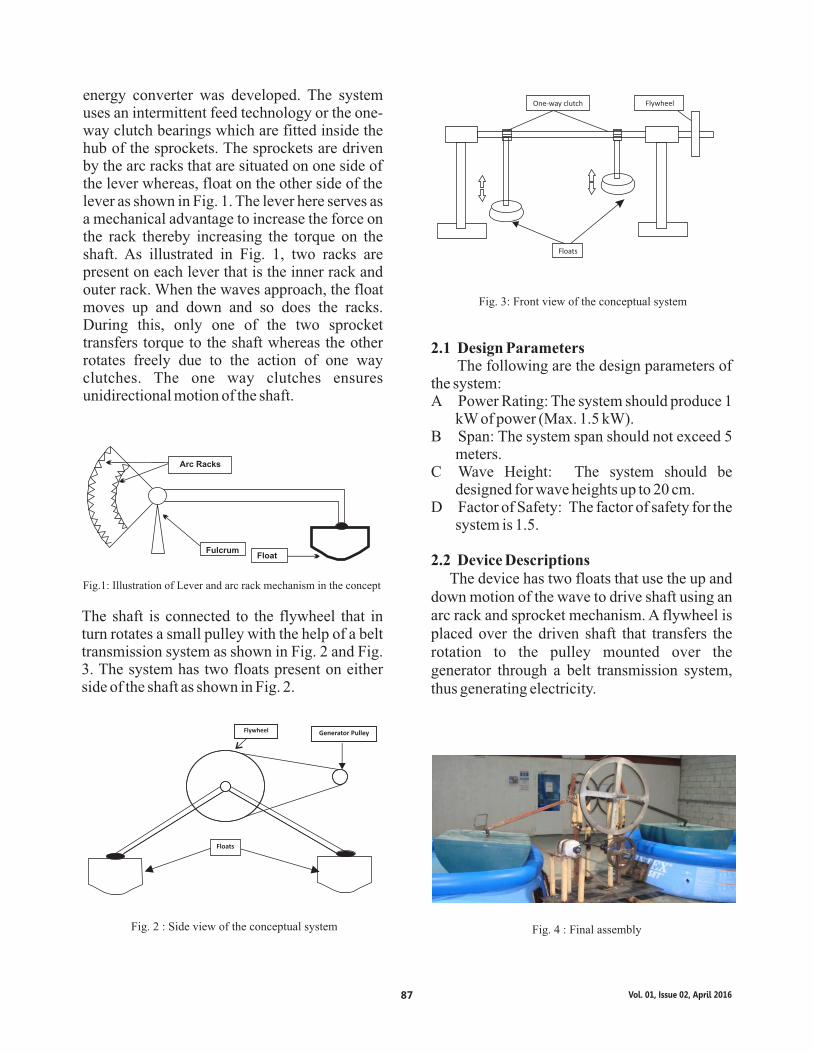
Fig.1: Illustration of Lever and arc rack mechanism in the concept
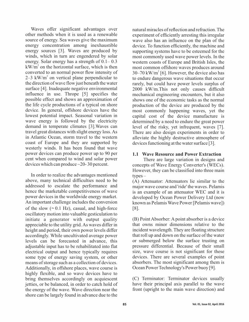
The shaft is connected to the flywheel that in turn rotates a small pulley with the help of a belt transmission system as shown in Fig. 2 and Fig. 3. The system has two floats present on either side of the shaft as shown in Fig. 2.
Fig. 3: Front view of the conceptual system
2.1 Design Parameters The following are the design parameters of the system:A Power Rating: The system should produce 1
kW of power (Max. 1.5 kW).B Span: The system span should not exceed 5
meters.C Wave Height: The system should be
designed for wave heights up to 20 cm.D Factor of Safety: The factor of safety for the
system is 1.5.
2.2 Device Descriptions The device has two floats that use the up and down motion of the wave to drive shaft using an arc rack and sprocket mechanism. A flywheel is placed over the driven shaft that transfers the rotation to the pulley mounted over the generator through a belt transmission system, thus generating electricity.
Arc Racks
FulcrumFloat
Fig. 2 : Side view of the conceptual system
Flywheel Generator Pulley
Floats
Floats
One-way clutch Flywheelenergy converter was developed. The system uses an intermittent feed technology or the one-way clutch bearings which are fitted inside the hub of the sprockets. The sprockets are driven by the arc racks that are situated on one side of the lever whereas, float on the other side of the lever as shown in Fig. 1. The lever here serves as a mechanical advantage to increase the force on the rack thereby increasing the torque on the shaft. As illustrated in Fig. 1, two racks are present on each lever that is the inner rack and outer rack. When the waves approach, the float moves up and down and so does the racks. During this, only one of the two sprocket transfers torque to the shaft whereas the other rotates freely due to the action of one way clutches. The one way clutches ensures unidirectional motion of the shaft.
Fig. 4 : Final assembly
Vol. 01, Issue 02, April 201687
2.3 Features As depicted in Fig. 5, intermittent feed systems ensures unidirectional rotation of shaft with help of one-way clutch bearings and captures both up and down motion of floats caused by the waves.
Fig. 5 : Intermittent feed system
It uses Arc-Rack concepts. The racks are perfectly aligned such that the sprockets move over the rack smoothly. A safe distance is maintained between the two sprockets to avoid collision. The sprocket is mounted over the shaft and is coupled with it using set screws. Provides a longer length of rack over which the sprocket runs.
Fig. 6 : Arc-Rack concept
The lever was fabricated by welding square beams of the designed length with one another to form a Y shape at one end and float connection at other end. The lever provides a mechanical advantage by exerting a greater force of the rack than that received on float by the waves.
Fig. 7 : Lever mechanism
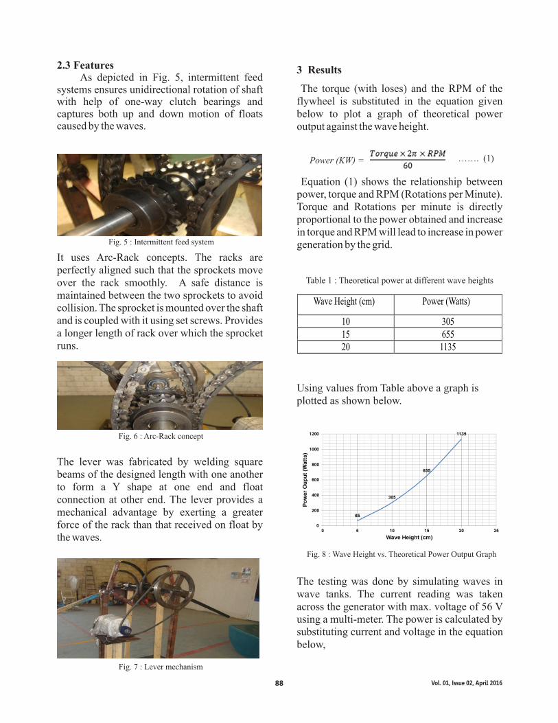
3 Results
The torque (with loses) and the RPM of the flywheel is substituted in the equation given below to plot a graph of theoretical power output against the wave height.
Power (KW) = ……. (1)
Equation (1) shows the relationship between power, torque and RPM (Rotations per Minute). Torque and Rotations per minute is directly proportional to the power obtained and increase in torque and RPM will lead to increase in power generation by the grid.
Wave Height (cm) Power (Watts)
10 30515 65520 1135
Table 1 : Theoretical power at different wave heights
Using values from Table above a graph is plotted as shown below.
Fig. 8 : Wave Height vs. Theoretical Power Output Graph
The testing was done by simulating waves in wave tanks. The current reading was taken across the generator with max. voltage of 56 V using a multi-meter. The power is calculated by substituting current and voltage in the equation below,
Vol. 01, Issue 02, April 201688
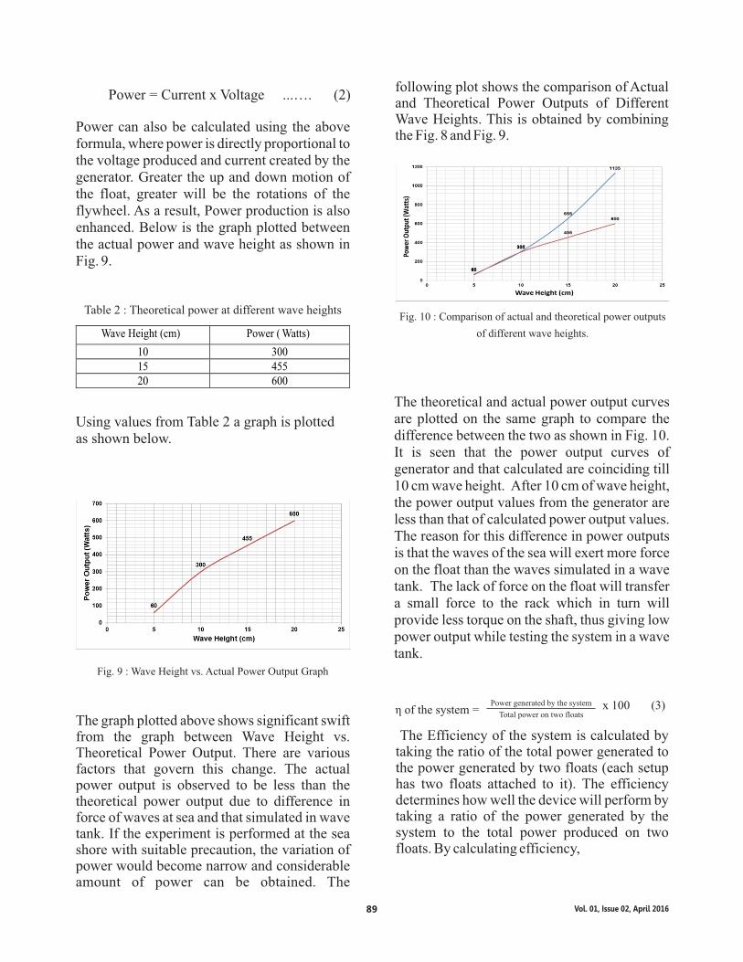
Power = Current x Voltage ...…. (2)
Power can also be calculated using the above formula, where power is directly proportional to the voltage produced and current created by the generator. Greater the up and down motion of the float, greater will be the rotations of the flywheel. As a result, Power production is also enhanced. Below is the graph plotted between the actual power and wave height as shown in Fig. 9.
Wave Height (cm) Power ( Watts)
10 30015 45520 600
Table 2 : Theoretical power at different wave heights
Using values from Table 2 a graph is plotted as shown below.
Fig. 9 : Wave Height vs. Actual Power Output Graph
The graph plotted above shows significant swift from the graph between Wave Height vs. Theoretical Power Output. There are various factors that govern this change. The actual power output is observed to be less than the theoretical power output due to difference in force of waves at sea and that simulated in wave tank. If the experiment is performed at the sea shore with suitable precaution, the variation of power would become narrow and considerable amount of power can be obtained. The
Fig. 10 : Comparison of actual and theoretical power outputs
of different wave heights.
The theoretical and actual power output curves are plotted on the same graph to compare the difference between the two as shown in Fig. 10. It is seen that the power output curves of generator and that calculated are coinciding till 10 cm wave height. After 10 cm of wave height, the power output values from the generator are less than that of calculated power output values. The reason for this difference in power outputs is that the waves of the sea will exert more force on the float than the waves simulated in a wave tank. The lack of force on the float will transfer a small force to the rack which in turn will provide less torque on the shaft, thus giving low power output while testing the system in a wave tank.
η of the system =Power generated by the system
Total power on two floatsx 100 (3)
The Efficiency of the system is calculated by taking the ratio of the total power generated to the power generated by two floats (each setup has two floats attached to it). The efficiency determines how well the device will perform by taking a ratio of the power generated by the system to the total power produced on two floats. By calculating efficiency,
following plot shows the comparison of Actual and Theoretical Power Outputs of Different Wave Heights. This is obtained by combining the Fig. 8 and Fig. 9.
Vol. 01, Issue 02, April 201689

Wave Height (cm) Efficiency (%)10 2915 4220 55
Table 3 : Efficiency of the system at different wave heights
0
20
40
0 10 20 30 40
Fig. 11: Wave Height vs. Efficiency Graph (1m dia. Float)
Fig. 11 shows the variation of efficiency of the system with the wave height achieved by the float of 1m diameter. The graph is directly proportional graph as it is a straight line increasing from lower value to higher value of wave height
4 Conclusion
Different types of existing wave harnesser technologies were analyzed namely tidal dam, tidal lagoon, over topping devices, oscillating water column technology underwater bi and unidirectional turbine technology tube type, float type etc. Research works suggest that systems with float type technology have reduced the efficiency due to the improper utilization of the float movements. Referring to different types of existing float type wave power harnesser technology, an innovative idea has been developed that involves effective usage of float movements. Waves are major sources for the generation of electrical energy. Ocean is a huge resource, and there are possibilities to harness energy from it so as to meet the global energy demands. This paper presents a few status of Wave Energy Converter (WEC) technology. The devices are studied and established. The companies and institutions that worked towards the development of such
devices are also realized. In order to have a solution for an increasing energy demand an effort has been made to design and construct an innovative wave energy conversion device After an extensive design and testing of the system, it was observed that the system can serve as a potential future alternative renewable energy converter. As the wave energy is an unlimited source of energy, this device is future-proof and will still be viable in the near-future era. The system can be conveniently designed further to operate on high wave heights, thereby increasing the power rating of the system. The installation of the system may also lead to the development of self - sufficient island cities, beach houses or resorts that do not rely on the conventional power plants for their electric supply needs. A series of such systems properly placed can serve as wave energy farms, which can be used for supplying continuous electric power. Any technological development in the field of energy do has some environmental effects. However, pollution and global warming is initiated by the fossil fuels plants irrespective of the size and location. Impacts caused by the technological development in the field of renewable energy are likely to be scale dependent and site specific. Therefore, site for the development must be chosen carefully in order to withstand alterations to the environment by the power devices. It is crucial to effectively develop this technology without harming the ocean. So before proceeding with a new technology, it is mandatory to prioritize the health of the marine atmosphere while harnessing clean energy.
References[1] Takashu P, Trenka A. Ocean Thermal
Energy Conversion. New York: Wiley,
1996.[2] Ted K.A. Brekken, Annette von
Jouanne, Hai Yue Han (2006) Ocean
Wave Energy Overview and Research at
Vol. 01, Issue 02, April 201690
Oregon State University, Oregon State
University Corvallis, Oregon, 97331.
[3] Clémen, A., McCullen, P., Falcăo, A.,
F io ren t ino , A . , Ga rbene r, F. ,
Hammarlund, K., Lemonis, G., Lewis,
T., Nielsen, K., Petrncini, S., Pontes, M.-
T., Schild, B.-O., Sjöström, P.,
Søresen,H.C., and Thrope, T. Wave
energy in Europe: current status and
prospectives. Renew. Sust. Energy Rev.,
2002,6(5), 405-431.
[4] Falnes, J. A review of wave-energy
extraction. Mar.Struct., 2007, 20,
185–201.
[5] Thorpe, T. W. A brief review of wave
energy, Technical Report no. R120,
Energy Technology Support Unit
(ETSU), A report produced for the UK
Department of Trade and Industry,
1999.
[6] Pelc, R. and Fujita, R. M. Renewable
energy from the ocean. Mar. Policy,
2002, 26(6), 471–479.
[7] Leijon, M., Danielsson, O., Eriksson,
M., Thorburn, K.,Bernhoff, H., Isberg,
J., Sundberg, J., Ivanova, I., Sjöstedt, E.
Å g r e n , O . K a r l s s o n , K . E . ,
andWolfbrandt, A. An electrical
approach to wave energy conversion.
Renew. Energy, 2006, 31, 1309–1319.
[8] Pelamis. Available from http://www.
pelamiswave.com and http://tinyurl.
com/pelamis.
[9] OPT- Ocean Power Technology.
A v a i l a b l e f r o m h t t p : / /
www.oceanpowertechnologies. com.
[10] Aquamarine Power. Available from
http:// aquamarinepower.com.
[11] Duckers, L. Wave energy. In Renewable
energy (Ed. G.Boyle), 2nd edition,
2004, ch. 8 (Oxford University
Press,Oxford, UK).
[12] Oceanlinx. Available from http:// www.
Oceanlinx.com.
[13] Anon (2002) “Bølgekraftforeningens
Konceptkatalog” Foreningen til Fremme
af Bølgekraft.
TM [14] Wavestar – Muliti point absorber
A v a i l a b l e f r o m
http://wavestarenergy.com.
[15] Kesayoshi Hadano, Katsuya Matsuoka,
Pallav Koirala, Keisuke Taneura &
Kimihiko Nakano (2010) “Study on the
Float-Type Wave Energy Converter
with Power Stabilization Technique” ,
Busan, Korea, The International Society
of Offshore and Polar Engineers.
[16] Anon (2006) “Technology White Paper
on Wave Energy Potential on the U.S.
Outer Continental Shelf” Minerals
Management Service, Renewable
Energy and Alternate Use Program, U.S.
Department of the Interior.
Vol. 01, Issue 02, April 201691