mechanical behavior and failure of composite pyramidal truss core sandwich columns
TRANSCRIPT
Composites: Part B 42 (2011) 938–945
Contents lists available at ScienceDirect
Composites: Part B
journal homepage: www.elsevier .com/locate /composi tesb
Mechanical behavior and failure of composite pyramidal truss coresandwich columns
Jian Xiong a,b, Li Ma a, Linzhi Wu a,⇑, Jiayi Liu a, Ashkan Vaziri b
a Center for Composite Materials and Structures, Harbin Institute of Technology, Harbin 150001, PR Chinab Department of Mechanical and Industrial Engineering, Northeastern University, Boston, MA 02115, USA
a r t i c l e i n f o
Article history:Received 30 July 2010Received in revised form 5 October 2010Accepted 31 December 2010Available online 20 January 2011
Keywords:A. Carbon fiberB. BucklingC. Analytical modelingD. Mechanical testing
1359-8368/$ - see front matter Crown Copyright � 2doi:10.1016/j.compositesb.2010.12.021
⇑ Corresponding author. Tel.: +86 451 86412549; faE-mail addresses: [email protected] (J. Xion
a b s t r a c t
A series of analytical and experimental investigations is presented to study the response and failure ofpyramidal truss core sandwich panels made of carbon fiber composite under axial compression. In theanalytical part of the study, three failure modes: (i) Euler or core shear macro-buckling, (ii) face wrin-kling, and (iii) face sheet crushing, were considered and theoretical relationships for predicting the failureload associated with each mode were presented. In the experimental part of the study, three different setsof specimens were manufactured to probe the three failure modes mentioned above. Pyramidal trusscores were fabricated using a hot-press molding technique and were bonded to composite face sheetsmade of fiber reinforced composite. The response of the sandwich panels under axial compression wasmeasured up to failure. The measured peak loads obtained in the experiments showed good agreementwith the analytical predictions. The experiments also provide insight into the post-failure response of thesandwich panels.
Crown Copyright � 2011 Published by Elsevier Ltd. All rights reserved.
1. Introduction
Sandwich panels with low density cores are traditionally man-ufactured using stochastic foams and lattice materials such as hex-agonal honeycombs [1–3]. The emergence of new manufacturingtechniques for building three-dimensional periodic cores (e.g.pyramidal and Kagome cores, X-cor trusses) has opened newopportunities for designing lightweight multifunctional structures[4–11]. An inherent part of this progress is the need to understandthe mechanical behavior of these novel structures. In this context,the available literature is mainly focused on the behavior of metalsandwich panels, due to their potential applications in buildinglarge scale structures and ships, as well as energy absorbent andprotective components. Use of fiber reinforced composites in sand-wich structures generally allows an additional weight reductionwithout jeopardizing the strength and performance of the struc-ture. Thus, sandwich panels made of fiber reinforced compositesare attractive for building ultra-light, high strength components,specifically for the aerospace industry and for flight structures[12–20].
Compared to metal sandwich panels, studying the behavior ofcomposite sandwich panels is more challenging due to the com-plex, and generally highly anisotropic, behavior of the composite.Most of the studies on the mechanical response of composite
011 Published by Elsevier Ltd. All
x: +86 451 86402386.g), [email protected] (L. Wu).
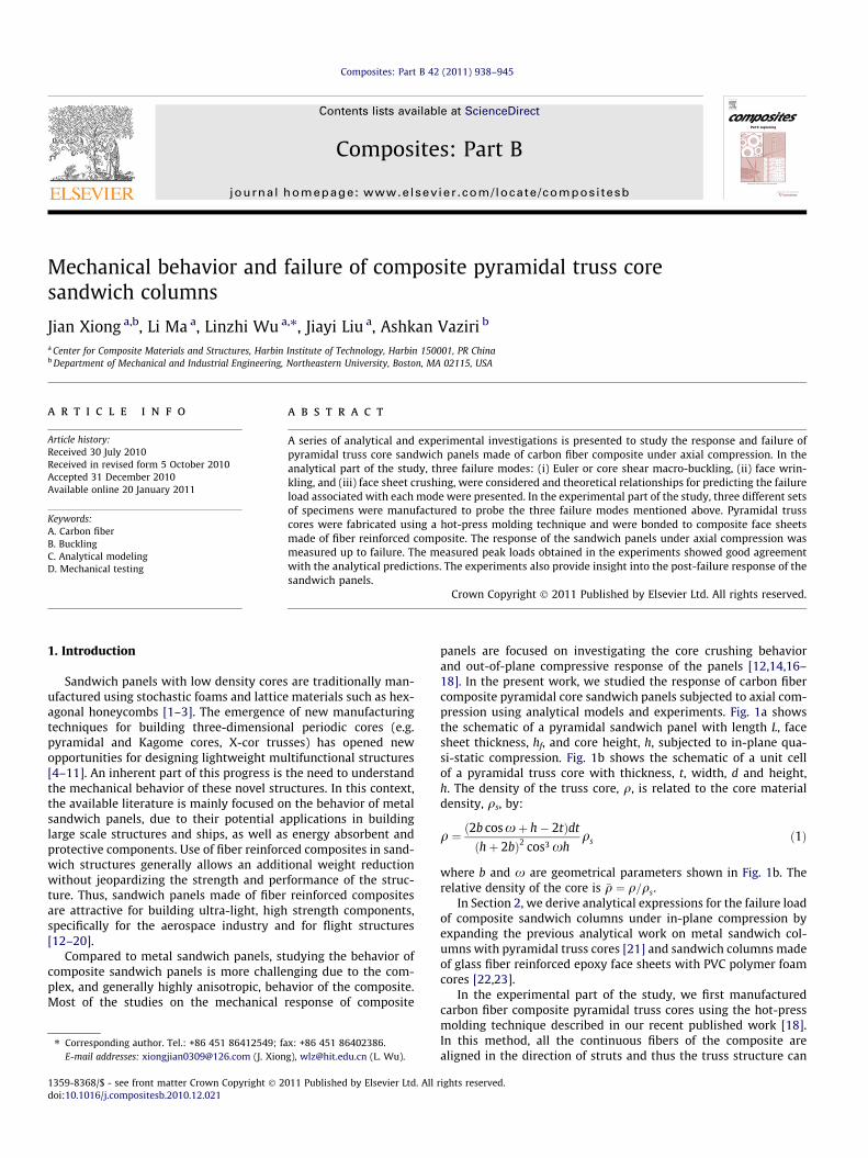
panels are focused on investigating the core crushing behaviorand out-of-plane compressive response of the panels [12,14,16–18]. In the present work, we studied the response of carbon fibercomposite pyramidal core sandwich panels subjected to axial com-pression using analytical models and experiments. Fig. 1a showsthe schematic of a pyramidal sandwich panel with length L, facesheet thickness, hf, and core height, h, subjected to in-plane qua-si-static compression. Fig. 1b shows the schematic of a unit cellof a pyramidal truss core with thickness, t, width, d and height,h. The density of the truss core, q, is related to the core materialdensity, qs, by:
q ¼ ð2b cos xþ h� 2tÞdt
ðhþ 2bÞ2 cos3 xhqs ð1Þ
where b and x are geometrical parameters shown in Fig. 1b. Therelative density of the core is �q ¼ q=qs.
In Section 2, we derive analytical expressions for the failure loadof composite sandwich columns under in-plane compression byexpanding the previous analytical work on metal sandwich col-umns with pyramidal truss cores [21] and sandwich columns madeof glass fiber reinforced epoxy face sheets with PVC polymer foamcores [22,23].
In the experimental part of the study, we first manufacturedcarbon fiber composite pyramidal truss cores using the hot-pressmolding technique described in our recent published work [18].In this method, all the continuous fibers of the composite arealigned in the direction of struts and thus the truss structure can
rights reserved.
fh
Ll
(a)
(b)
Fig. 1. (a) Schematic diagram of the compression test assembly. (b) Sketch of theunit cell of the pyramidal core.
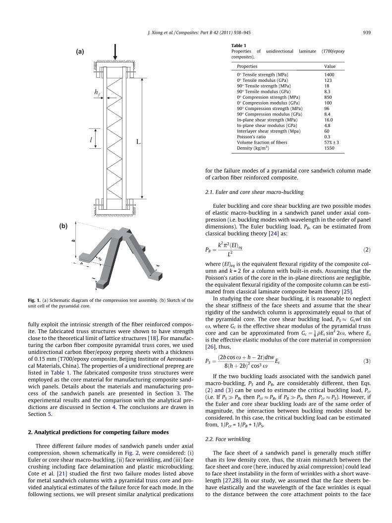
Table 1Properties of unidirectional laminate (T700/epoxycomposites).
Properties Value
0� Tensile strength (MPa) 14000� Tensile modulus (GPa) 12390� Tensile strength (MPa) 1890� Tensile modulus (GPa) 8.30� Compression strength (MPa) 8500� Compression modulus (GPa) 10090� Compression strength (MPa) 9690� Compression modulus (GPa) 8.4In-plane shear strength (MPa) 16.0In-plane shear modulus (GPa) 4.8Interlayer shear strength (Mpa) 60Poisson’s ratio 0.3Volume fraction of fibers 57% ± 3Density (kg/m3) 1550
J. Xiong et al. / Composites: Part B 42 (2011) 938–945 939
fully exploit the intrinsic strength of the fiber reinforced compos-ite. The fabricated truss structures were shown to have strengthclose to the theoretical limit of lattice structures [18]. For manufac-turing the carbon fiber composite pyramidal truss cores, we usedunidirectional carbon fiber/epoxy prepreg sheets with a thicknessof 0.15 mm (T700/epoxy composite, Beijing Institute of Aeronauti-cal Materials, China). The properties of a unidirectional prepreg arelisted in Table 1. The fabricated composite truss structures wereemployed as the core material for manufacturing composite sand-wich panels. Details about the materials and manufacturing pro-cess of the sandwich panels are presented in Section 3. Theexperimental results and the comparison with the analytical pre-dictions are discussed in Section 4. The conclusions are drawn inSection 5.
2. Analytical predictions for competing failure modes
Three different failure modes of sandwich panels under axialcompression, shown schematically in Fig. 2, were considered: (i)Euler or core shear macro-buckling, (ii) face wrinkling, and (iii) facecrushing including face delamination and plastic microbuckling.Cote et al. [21] studied the first two failure modes listed abovefor metal sandwich columns with a pyramidal truss core and pro-vided analytical estimates of the failure force for each mode. In thefollowing sections, we will present similar analytical predications
for the failure modes of a pyramidal core sandwich column madeof carbon fiber reinforced composite.
2.1. Euler and core shear macro-buckling
Euler buckling and core shear buckling are two possible modesof elastic macro-buckling in a sandwich panel under axial com-pression (i.e. buckling modes with wavelength in the order of paneldimensions). The Euler buckling load, PB, can be estimated fromclassical buckling theory [24] as:
PB ¼k2p2ðEIÞeq
L2 ð2Þ
where (EI)eq is the equivalent flexural rigidity of the composite col-umn and k = 2 for a column with built-in ends. Assuming that thePoisson’s ratios of the core in the in-plane directions are negligible,the equivalent flexural rigidity of the composite column can be esti-mated from classical laminate composite beam theory [25].
In studying the core shear buckling, it is reasonable to neglectthe shear stiffness of the face sheets and assume that the shearrigidity of the sandwich column is approximately equal to that ofthe pyramidal core. The core shear buckling load, PS � Gcwl sinx, where Gc is the effective shear modulus of the pyramidal trusscore and can be approximated from Gc ¼ 1
8�qEs sin2 2x, where Es
is the effective elastic modulus of the core material in compression[26], thus,
PS ¼ð2b cos xþ h� 2tÞdtw
8ðhþ 2bÞ2 cos3 xEs ð3Þ
If the two buckling loads associated with the sandwich panelmacro-buckling, PS and PB, are considerably different, then Eqs.(2) and (3) can be used to estimate the critical buckling load, Pcr
(i.e. If PS� PB, then Pcr � PB, if PB� PS, then Pcr � PS). However, ifthe Euler and core shear buckling loads are of the same order ofmagnitude, the interaction between buckling modes should beconsidered. In this case, the critical buckling load can be estimatedfrom, 1/Pcr = 1/PB + 1/PS.
2.2. Face wrinkling
The face sheet of a sandwich panel is generally much stifferthan its low density core, thus, the strain mismatch between theface sheet and core (here, induced by axial compression) could leadto face sheet instability in the form of wrinkles with a short wave-length [27,28]. In our study, we assumed that the face sheets be-have elastically and the wavelength of the face wrinkles is equalto the distance between the core attachment points to the face

(c) (e) (d) (a) (b)
Fig. 2. Failure modes in sandwich columns subjected to edge compression. (a) Euler macro-buckling; (b) core shear macro-buckling; (c) face sheet wrinkling; (d) face sheetmicrobuckling; (e) face sheet delamination.
Table 2Stress-based three-dimensional Hashin criteria. XT and XC are the tensile andcompressive strength of fibers, YT and YC are the tensile and compressive strengthof matrix, ZT and ZC are the tensile and compressive strength of the unidirectionallaminate in the normal direction. rij and Sij is the component of the stress tensor andshear tensor defined in the classical form, where x and y are the in-plane axes.
Failure mode Failure criteria
Fiber tensile failure (rxx > 0) (rxx/XT)2 + (rxy/S12)2 + (rxz/S13)2 P 1Fiber compressive failure (rxx < 0) (rxx/XC)2 P 1Matrix tensile cracking (ryy > 0) (ryy/YT)2 + (rxy/S12)2 + (ryz/S23)2 P 1Matrix compressive cracking (ryy < 0) (ryy/YC)2 + (rxy/S12)2 + (ryz/S23)2 P 1Fiber–matrix shear cracking (rxx < 0) (rxx/XC)2 + (rxy/S12)2 + (rxz/S13)2 P 1Delamination in tension (rzz > 0) (rzz/ZT)2 + (rxz/S13)2 + (ryz/S23)2 P 1Delamination in compression (rzz < 0) (rzz/ZC)2 + (rxz/S13)2 + (ryz/S23)2 P 1
Fig. 3. Schematic of the manufacturing molds used for fabrication of the carbonfiber pyramidal truss cores.
940 J. Xiong et al. / Composites: Part B 42 (2011) 938–945
sheet, denoted by l in Fig. 1a, where l = (2h � 4t + 4b) cos x. Theforce associated with the elastic wrinkling of the face sheet, PW,can be estimated from
PW ¼2p2ðEIÞf
l2ð4Þ
where (EI)f is the flexural rigidity of the face sheet in respect to thepanel mid-plane, which can be obtained using classical laminatecomposite beam theory [25].
2.3. Face sheet crushing
Since the pyramidal truss core is much more compliant com-pared to the face sheets, the face sheet crushing load can be esti-mated from,
PFY ¼ 2rfyhf w ð5Þ
where rfy is the microbuckling strength of the composite face sheet,which depends on the degree of fiber misalignment and the matrixshear strength (see for example the review by Fleck [22,29]). In thepresent study, we calculated rfy using the composite laminate the-ory [25] and Hashin criteria with a sudden degradation model [30–32] using the ANSYS Parametric Design Language (APDL). The Ha-shin criteria in the three-dimensional form are given in Table 2.
3. Manufacturing of sandwich panels
Fig. 3 shows the schematic of the mold used for fabrication ofthe cores. The mold consists of four different parts: (1) up webframes, (2) down web frames, (3) blocks and (4) the base tooling,which was made of chrome steel. The expansion blocks used inthe process are cast silicon rubber and were laid into the space be-tween the base tooling and the down web frames. Fig. 4a shows anexample of the manufactured composite pyramidal lattice struc-tures, where each strut of the pyramidal truss is made of six slen-der laps and has a thickness, t = 0.9 mm. The pyramidal trussstructure shown in Fig. 4a has b = 4 mm, h = 15 mm, d = 3 mm,x = 450, and relative density �q ¼ 1:81%. The sandwich panels were
fabricated by bonding the pyramidal truss core to flat carbon fiberreinforced face sheets with an adhesive (08–57, Heilongjiang Insti-tute of Petrochemical Industry). Fig. 4b shows an example of thesandwich panel with a pyramidal truss core with b = 4 mm,h = 15 mm, d = 3 mm, x = 450, �q ¼ 1:25%.
Three sets of sandwich panels with different face sheet thick-ness, hf, length, L and strut thickness, t, were fabricated to explorethe failure modes identified in Section 2. Table 3 shows the dimen-

Fig. 4. (a) Fabricated carbon fiber composite pyramidal truss structures with �q ¼ 1:81%. (b) Sandwich panel with carbon fiber composite pyramidal truss core with�q ¼ 1:25%.
Table 3Dimensions of the specimens and the predicted and measured failure loads and collapse modes. The failure modes in this table are abbreviated: FW (face wrinkling); FC (facesheet crushing); CS (core shear macro-buckling).
Specimen r (kg/m3) w (mm) L (mm) hf (mm) Analytical Experiment
Failure mode Failure force (kN) Failure mode Peak force (kN)
1 26.20 100 200 2.00 CS 43.08 CS 35.41FW 44.59FC 126.89
2 32.03 99 99 0.58 CS 63.66 FW 2.44FW 2.65FC 27.44
3 741.92 71 142 2.38 CS 109.19 FC 96.36FW 366.13FC 107.21
Fig. 5. (a) The measured collapse response of sandwich column specimen 1. The specimen collapses in a core shear macro-buckling mode. The analytical prediction of thecollapse load is included. (b) Photographs of the deformation history of the panel in (a). (c) Debonding image of a typical node-face sheet cross-section A–A after macro elasticbuckling mode. (d) Strut fracturing image of a typical node-face sheet cross-section B–B after core shear macro-buckling mode.
J. Xiong et al. / Composites: Part B 42 (2011) 938–945 941

942 J. Xiong et al. / Composites: Part B 42 (2011) 938–945
sions of each set of sandwich panels, as well as the analytical pre-dictions for each failure mode and the measured peak load and theobserved failure mode. The details of the compression test and theresults are discussed in the following section.
Fig. 6. (a) The measured collapse response of sandwich column specimen 2. The specimeincluded. (b) Photographs of the deformation history of the panel in (a). (c) Debonding
4. Compressive response of sandwich panels
The response of pyramidal core sandwich columns was mea-sured using INSTRON 5500 following ASTM C365/C 364M-05
n collapses in a face wrinkling mode. The analytical prediction of the collapse load isimage of a typical node-face sheet cross-section A–A after face wrinkling.

J. Xiong et al. / Composites: Part B 42 (2011) 938–945 943
[33]. The axial compression tests were carried out in the quasi-sta-tic regime with a nominal displacement rate of 0.5 mm/min. Atleast two tests were carried out for each column geometry to en-sure the repeatability of the results.
4.1. Euler or core shear macro-buckling
According to the analytical study presented in Section 2.1, coreshear buckling is the dominant elastic macro-buckling mode forsandwich panels with thick face sheets and thin struts. No practicallaboratory scale column could be designed to probe the Euler buck-ling mode. The measured compressive response of specimen 1(with face sheets [0/+45/�45/90]4 and L = 200 mm, hf = 2.0 mm,h = 11.2 mm, t = 0.52 mm, q = 26.20 kg/m3) is depicted in Fig. 5,along with a montage of photographs showing the specimen defor-mation and fracture at different stages of loading (I: initial, II: priorto buckling, III: after buckling).
After the initial linear response, specimen 1 buckles and bendsoutward and the resisting force of the column decreases sharply.
Fig. 7. (a) The measured collapse response of specimen 3. (b) Photographs of the deformecrushing and face sheet delamination, IV: final deformed configuration), showing the comof the face sheet delamination taken from section A–A in (b), stage III. (d) Debonding im
According to Eq. (3), the buckling load of the sandwich panel isPS � 43.08 kN (note that for this sandwich panel PB� PS). The mea-sured peak value is �35.41 kN (standard deviation �3.17 kN),about 18% lower than the theoretical prediction. The load–dis-placement curve drops sharply after core shear macro-buckling.The response of the panel at this stage of loading is governed bya combination of core shear buckling and debonding of the strutsfrom the face sheets as can be seen in Fig. 5c. The debonding occurssince the bonding between the core and face sheet is not strong en-ough to transmit the constraints of the cores. In addition to deb-onding, fracture of the trusses was also observed prior to theoverall failure of the panel, as shown in Fig. 5d.
4.2. Face wrinkling
Fig. 6a shows the response of specimen 2 with face sheets [+45/�45/0/�45/+45] and L = 99 mm, h = 12.8 mm, hf = 0.58 mm,t = 0.8 mm, and q = 32.03 kg/m3. Fig. 6b shows the deformed con-figurations of the sandwich panel at different stages of loading.
d panel at different stages of loading (I: Initial, II: before failure, III and III: after faceplete debonding of the face sheets from the core and outward buckling. (c) An imageage of a strut-face sheet after face delamination mode (section B–B in (b), stage IV).

944 J. Xiong et al. / Composites: Part B 42 (2011) 938–945
The load–displacement is linear prior to wrinkling of the face sheetsup to a compressive load �2.44 kN (standard deviation �0.02 kN).The predicted failure load for specimen 2 is approximately2.65 kN and is somewhat higher than the measured peak value.The response was followed by a softening behavior and the ampli-tude of the face sheet wrinkles became larger as the applied com-pressive deformation was increased. This was followed by coredebonding from the face sheet, as the bonding layers were notstrong enough to transmit the constraints of the pyramidal trusscores. The debonding occurred relatively gradually between thepyramidal truss core and face sheets, leading to multiple drops inthe load carrying capacity of the panel (stages III to V) – see Fig. 6c.
4.3. Face sheet crushing
Fig. 7a shows the measured compressive response of specimen 3with face sheets [0/+45/�45/90]5 and L = 142 mm, hf = 2.38 mm,t = 2.4 mm, h = 13.6 mm and q = 71.92 kg/m3. Fig. 7b shows the de-formed configuration of the sandwich panel at different stages ofdeformation. In this experiment, a progressive end-crushing of car-bon fiber composite sandwich panels was observed. As the com-pressive load reaches the critical load associated with the facecrushing, both face sheets get crushed at the bottom of the test fix-ture, Fig. 7c. Using the numerical method presented in Section 2.3,we estimated rfy = 317.22 MPa, for this panel configuration. Theanalytical estimate of the critical load based on Eq. (5) is�107.21 kN. The measured peak value in Fig. 7a is 96.4 kN (standarddeviation�8.70 kN) and is about 10% lower than the analytical pre-diction. This discrepancy is attributed to the imperfections in themanufactured specimens, as well as the assumptions made indeveloping the simple analytical model presented in Section 2.3and in estimating the microbuckling strength of the composite facesheet. The local delamination of the face sheet near the clampedends of the panel reduces the overall strength of the sandwich panel.However, the sandwich panel regained its strength partially as thedeformation was increased. After a second peak load of �78 kN,the sandwich panel lost its integrity, as the core completely debond-ed from one of the face sheets, and each part of the panel bent out-ward (Stage IV). Fig. 7d shows an image of the face sheet after coredebonding, taken after the complete failure of the panel.
5. Concluding remarks
We studied the compressive response and failure of compositesandwich panels with pyramidal truss cores under axial compres-sion. Our investigation complements the previous studies on theresponse and performance of lightweight sandwich panels withcomplex core construction and provides insight into the failuremechanisms of composite sandwich panels. In the analytical partof the study, three different failure modes were considered andtheoretical models were presented to estimate the failure loadassociated with each mode. In the experimental part of the work,we used the analytical estimates to fabricate sandwich columnsthat allowed us to probe the three different failure regimes. Themeasured peak loads were in reasonable agreement with the ana-lytical predictions. In general, after the initial peak load, the bondstrength was one of the key limiting factors in the performanceof the panels. Debonding between the core and face sheets wereobserved in all experiments, leading to a reduction in the load car-rying capacity of the panels in the post-failure regime.
Acknowledgements
This work was supported by the National Science Foundation ofChina under Grant Nos. 90816024 and 10872059, the Major State
Basic Research Development Program of China (973 Program) un-der Grant No. 2011CB610303, the Program of Excellent Team inHarbin Institute of Technology (W.L.) and the NSF CMMI Programunder award # 1065759 (A.V.). L.M. acknowledges the Programfor New Century Excellent Talents in University under Grant No.NCET-08-0152. The program for excellent Doctoral Newcomer inMinistry of Education of the People’s Republic of China (X.J.). Thesupport provided by China Scholarship Council (CSC) during a visitof Jian Xiong’ to Northeastern University is acknowledges.
References
[1] Gibson LJ, Ashby MF. Cellular solids: structure and properties. Cambridge:Cambridge University Press; 1997.
[2] Ashby MF, Evans AG, Fleck NA, Gibson LJ, Hutchinson JW, Wadley HNG. Metalfoams: a design guide. London: Butterworth/Heinemann; 2000.
[3] Smith BH, Hutchinson JW, Evans AG. Measurement and analysis of thestructural performance of cellular metal sandwich construction. Int J Mech Sci2001;43(8):1945–63.
[4] Queheillalt DT, Murty Y, Wadley HNG. Mechanical properties of an extrudedpyramidal lattice truss sandwich structure. Scripta Mater 2008;58:76–9.
[5] Kooistra GW, Wadley HNG. Lattice truss structures from expanded metalsheet. Mater Des 2007;28(2):507–14.
[6] Queheillalt DT, Wadley HNG. Pyramidal lattice truss structures with hollowtrusses. Mater Sci Eng A 2005;397:132–7.
[7] Yungwirth CJ, Radford DD, Aronson M, Wadley HNG. Experimental assessmentof the ballistic response of composite pyramidal lattice truss structures.Composite Part B 2008;39:556–69.
[8] Lee BK, Kang KJ. Compression strength of tube-woven Kagome truss cores.Scripta Mater 2008;58:76–9.
[9] Lee BK, Kang KJ. A parametric study on compressive characteristics of wire-woven bulk Kagome truss cores. Compos Struct 2010;92(2):445–53.
[10] Deshpande VS, Fleck NA, Ashby MF. Effective properties of the octet-trusslattice material. J Mech Phys Solids 2001;49(8):1747–69.
[11] Brien TK, Paris IL. Exploratory investigation of failure mechanisms in transitionregions between solid laminates and X-cor truss sandwich. Compos Struct2002;57:189–204.
[12] Finnegan K, Kooistra G, Wadley HNG, Deshpande VS. The compressiveresponse of carbon fiber composite pyramidal truss sandwich cores. Int JMater Res 2007;98(12):1264–72.
[13] Ashby MF, Bréchet YJM. Designing hybrid materials. Acta Mater2003;51(19):5801–21.
[14] Russell BP, Deshpande VS, Wadley HNG. Quasistatic deformation and failuremodes of composite square honeycombs. J Mech Mater Struct2008;3(7):1315–40.
[15] Fan HL, Meng FH, Yang W. Sandwich panels with Kagome lattice coresreinforced by carbon fibers. Compos Struct 2007;81(4):533–9.
[16] Wang B, Wu LZ, Ma L, Wang Q, Du SY. Fabrication and testing of carbon fiberreinforced truss core sandwich panels. J Mater Sci Technol 2009;25(4):547–50.
[17] Wang B, Wu LZ, Ma L, Sun YG, Du SY. Manufacturing and mechanical behaviorof the sandwich structure with carbon fiber-reinforced pyramidal lattice trusscores. Mater Des 2010;31(5):2659–63.
[18] Xiong J, Ma L, Wu LZ, Wang B, Vaziri A. Fabrication and crushing behavior oflow density carbon fiber composite pyramidal truss structures. Compos Struct2010;92:2695–702.
[19] Heimbs S, Cichosz J, Klaus M, Kilchert S, Johnson AF. Sandwich structures withtextile-reinforced composite foldcores under impact loads. Compos Struct2010;92:1485–97.
[20] Fan HL, Fang DN, Chen LM, Dai Z, Yang W. Manufacturing and testing of a CFRCsandwich cylinder with Kagome cores. Compos Sci Technol 2009;69(15–16):2695–700.
[21] Cote F, Biagi R, Smith HB, Deshpande VS. Structural response of pyramidal coresandwich columns. Int J Solids Struct 2007;44(10):3533–56.
[22] Fleck NA, Sridhar I. End compression of sandwich columns. Composites: Part A2002;33(3):353–9.
[23] Vadakke V, Carlsson LA. Experimental investigation of compression failure ofsandwich specimens with face/core debond. Composite Part B2004;35:583–90.
[24] Allen HG. Analysis and design of structural sandwich panels. NewYork: Pergamon Press; 1969.
[25] Jones RM. Mechanics of composite materials. International studentedition. Tokyo: McGraw-Hill Kogakusha, Ltd.; 1975.
[26] Deshpande VS, Fleck NA. Collapse of truss core sandwich beams in 3-pointbending. Int J Solids Struct 2001;38(36–37):6275–305.
[27] Chen X, Hutchinson JW. Herringbone buckling patterns of compressed thinfilms on compliant substrates. J Appl Mech 2004;71:597–603.
[28] Genzer J, Groenewold J. Soft matter with hard skin: from skin wrinkles totemplating and material characterization. Soft Matter 2006;2:310–23.
[29] Fleck NA. Compressive failure of fiber composites. Adv Appl Mech1997;33:43–117.
[30] Hashin Z. Failure criteria for unidirectional fiber composites. J Appl Mech1980;47:329–34.

J. Xiong et al. / Composites: Part B 42 (2011) 938–945 945
[31] Shokrieh MM, Lessard LB. Progressive fatigue damage modeling of compositematerials, part I: modeling. J Compos Mater 2000;34(13):1056–80.
[32] Garnich M, Akula V. Review of degradation models for progressive failureanalysis of fiber reinforced polymer composites. Appl Mech Rev 2009;62:010801-1–010801-33.
[33] ASTM: C365/C 364M-06 standard test method for end compressive propertiesof sandwich cores. West Conshohocken (PA): ASTM Int; 2006.