mechanical and metallurgical concerns in ammonia plants …€¦ · mechanical and metallurgical...
TRANSCRIPT

Mechanical and Metallurgical Concerns in Ammonia Plants
by Davide Bassi
Ammonia Casale S.A. Lugano, Switzerland
PDF created with pdfFactory trial version www.pdffactory.com

Mechanical and Metallurgical Concerns in Ammonia Plants
AMMONIA CASALE is a company well known for its activity in the field of ammonia plants. In the last decade the company has designed and built grass-roots ammonia units, which are now on-stream, as well as revamped any type of existing plants through the use of innovative technologies.
The company’s long experience on different types of plant has given it a deep knowledge of the available technologies which, combined with CASALE innovative know-how, allows it to select the most appropriate solution for any specific case. That is particularly true for mechanical and metallurgical aspects, which are a key aspect of ammonia plants, especially when they have a bearing on reliability and safety.
This paper describes the design choices made by CASALE regarding mechanical and metallurgical aspects.
PDF created with pdfFactory trial version www.pdffactory.com

Mechanical and Metallurgical Concerns in Ammonia Plants
FOREWORD
Reliability, safety and maintainability in the design and construction of petrochemical process plants and equipment primarily rely on the application of various codes of practice or design, which are based on the wide experience and knowledge of professional experts and specialists in the industry. Such application is backed up by the experience of local plant managers, engineers and operators who have direct experience in the operation of the relevant type of plant.
Plant safety and reliability have to be taken into special consideration right from the start of the project and should be developed in each step of the project life, covering all parts of the plant. Metallurgical and mechanical features are among the most important aspects of plant safety and reliability.
This paper describes the choices concerning mechanical and metallurgical features made by CASALE during the design, engineering and construction stages to reach the highest standards of safety and reliability.
The aspects to be considered in the selection of the mechanical and metallurgical features are:
● Definition of the most appropriate flow scheme and operational parameters of each equipment item or unit according to the “state of the art” of the available proven technology.
● Definition of the most appropriate design condition and material selection for all equipment items or units of the whole plant.
● Definition of the best design solutions for the defined conditions and material selection. ● Full development of the design solution according to the best available technologies. ● Selection of the most appropriate supplier of any equipment, with particular care for the critical
items, which can assure not only the best performance but also the most proven design from a reliability and safety point of view.
● Compliance with the monitoring and maintenance procedures to preserve the equipment characteristics and prevent failures and early deterioration.
MATERIAL SELECTION AND DESIGN CONDITIONS
The selection of the correct metallurgy and design features of any plant component is one of the most important tasks during the basic engineering phase. It starts with the definition of the most appropriate design conditions and material selection for all equipment items or units of the whole plant.
Depending on the process plant, different conditions, related to the particular combination of gas composition, temperature and pressure govern the most appropriate material and design conditions selection.
CASALE analyses all plant sections in detail and issues a final “Material Selection Diagram and Design Condition”, summarizing in a congruent and easy way the choice of equipment materials and design conditions, as well as piping materials, corrosion allowances, rating and design conditions (see Fig. 1).
This document, along with the equipment process data sheets, is the baseline for the detailed metallurgical and mechanical definition of all plant components.
PDF created with pdfFactory trial version www.pdffactory.com

Mechanical and Metallurgical Concerns in Ammonia Plants
Fig. 1 – Material selection diagram and design conditions
AMMONIA PLANT MATERIAL SELECTION
The material selection for the front end of an ammonia plant is basically governed by the fact that the process gas is hydrogen-rich, at high temperature and moderate pressure. So the front section of the ammonia plant operates in what is known as hydrogen service and the material selection must respect the minimum requirement stated by API standard 941. In addition, the material selection takes account of any possible chemical corrosion and the use of stainless steel is adopted wherever required in order to increase plant safety and reliability and assure trouble-free running.
The material selection for the synthesis loop of an ammonia plant is mainly governed by the fact that process gas is rich in hydrogen with a considerable quantity of gaseous ammonia at high pressure and temperature. These two components and their combination at the typical operating condition of an ammonia loop require a specific material selection and equipment design to avoid problems resulting from two specific phenomena: hydrogen attack and nitriding. Again, the material selection must be in conformity with the requirements of API standard 941, while the design of the relevant equipment requires deep knowledge of the problems and specific experience.
AMMONIA PLANT CRITICAL EQUIPMENT DESIGN
Ammonia plants incorporate a certain number of critical items which are of the greatest importance from the point of the performance, safety and reliability of the plant.
AMMONIA CASALE developed its own technology, and can directly supply a certain number of proprietary items and critical equipment that characterize and define its ammonia plants in the world.
PDF created with pdfFactory trial version www.pdffactory.com

Mechanical and Metallurgical Concerns in Ammonia Plants
AMMONIA CASALE proprietary items are:
● Pre-reformer ● Secondary reformer burner ● Ammonia synthesis converter. ● Synloop steam superheater / waste heat boiler / BFW pre-heater. ● Axial radial shift converters. ● Make up gas wash ejector
Some of the specially developed solutions for key items of the ammonia plant are set out below.
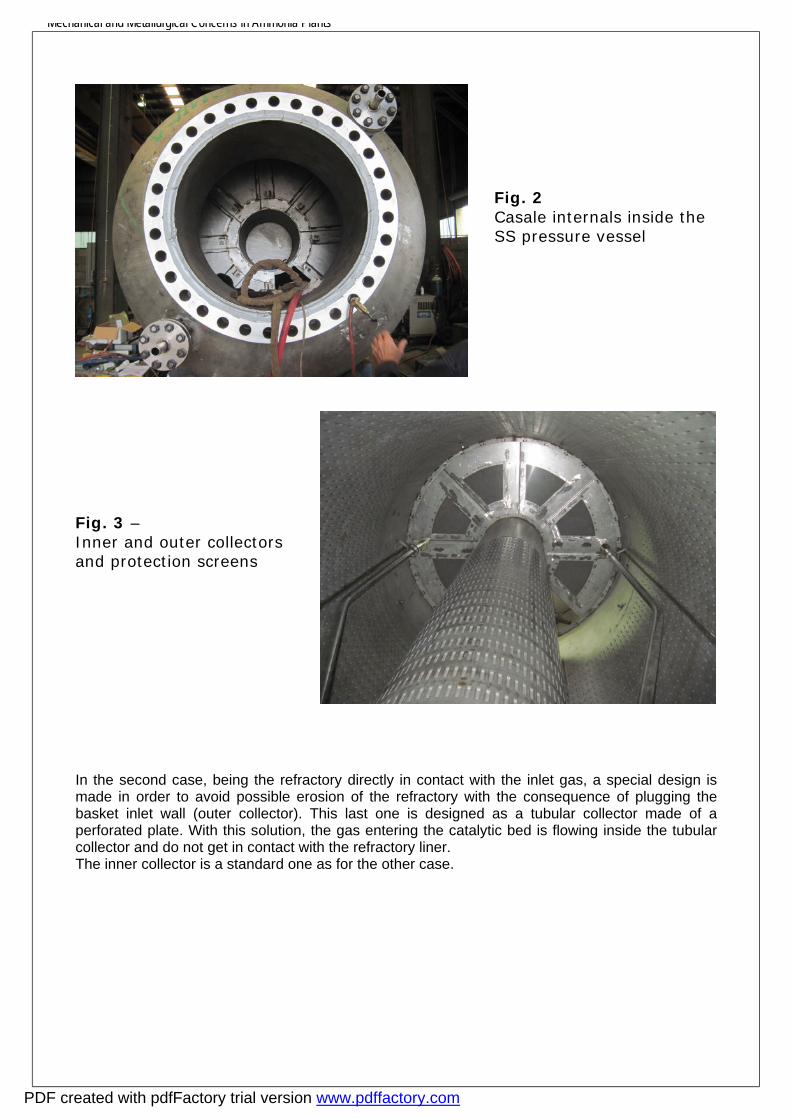
Pre-reformer The pre-reforming reactors convert the hydrocarbon impurities in the gas to hydrogen, methane, CO and CO2 only, enabling to maintain the operation of the primary reforming stable, and therefore making it possible to reduce the S/C ratio. The pre-reforming reactor by AMMONIA CASALE is designed according to the well-known axial-radial technology for catalyst beds. The advantages of using this technology for pre-reforming reactors are: • the low pressure drop achievable • the use of small-size catalyst The small-size catalyst has two advantages in comparison with the large-size one: • higher sulphur pick-up, resulting in a longer life, since sulphur is the main poison; • greater activity. This means that, with respect to the larger size catalyst, it is possible to reduce the catalyst volume to achieve the same life or to attain a longer life with the same volume. Thanks to the pre-reformer installation, it is, therefore, possible to operate the primary reformer smoothly, with stable operating conditions and to reduce the steam carbon ratio to the primary reformer, as the only feed gas is methane plus steam, CO, CO2 and hydrogen. It is also possible to use the natural gas type catalyst that is more active, and to increase the reforming capacity. The pre-reformer operates at high temperature and moderate pressure and hydrogen content. Those conditions normally involve the use of stainless steel AISI 321H or 347H, that are Ti/Nd stabilized and have higher allowable stresses compare to other stainless or low alloy steel. The relatively thin plates required for the construction of the internals do not cause any problems in terms of delivery and cost. For the pressure vessel, however, two solutions may be considered: a complete stainless steel construction or carbon steel with internal refractory. The choice is normally a question of price and/or delivery time. CASALE can suit the clients requirements on this regards and adapt the internals accordingly. In the first case, design of the internals is the classical CASALE with outer and inner collector (the first one being the gas inlet while the second the outlet). The inner and outer collectors may be manufactured in single pieces and inserted into the SS pressure vessel before welding its top head to the shell. In this way, significant time may be saved at side during construction phase.
PDF created with pdfFactory trial version www.pdffactory.com
Mechanical and Metallurgical Concerns in Ammonia Plants
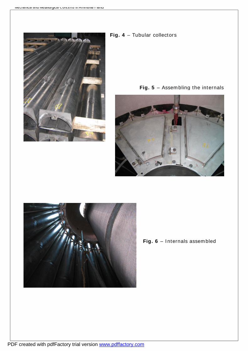
In the second case, being the refractory directly in contact with the inlet gas, a special design is made in order to avoid possible erosion of the refractory with the consequence of plugging the basket inlet wall (outer collector). This last one is designed as a tubular collector made of a perforated plate. With this solution, the gas entering the catalytic bed is flowing inside the tubular collector and do not get in contact with the refractory liner. The inner collector is a standard one as for the other case.
Fig. 3 – Inner and outer collectors and protection screens
Fig. 2 Casale internals inside the SS pressure vessel
PDF created with pdfFactory trial version www.pdffactory.com
Mechanical and Metallurgical Concerns in Ammonia Plants
Fig. 6 – Internals assembled
Fig. 4 – Tubular collectors
Fig. 5 – Assembling the internals
PDF created with pdfFactory trial version www.pdffactory.com

Mechanical and Metallurgical Concerns in Ammonia Plants
Secondary reformer burner CASALE CHEMICALS has extensive experience in the design of secondary reformer burners for ammonia production; the worldwide acceptance of its burners is testament to that. CASALE CHEMICALS burners are installed in Indonesia, China, Russia, Iran and Saudi Arabia with capacities ranging from 350 up to 2,000 MTD in ammonia. The first unit, a 700 MTD burner, was started-up in Indonesia in June 2002.
All CASALE burners are designed for low pressure drop on the air stream side, which increases the capability of the air compressor, and for low methane slip. It is therefore possible to revamp a secondary reformer by simply replacing the existing burner with a completely new one, without any modification to the existing secondary reformer vessel or to the external piping.
The main mechanical features of the CASALE design for the secondary reformer burner are the low temperature of the burner wall and the absence of refractory lining on the burner tip. The burner tip is kept cool by the air flow over its surfaces.
The selection of adequate materials is extremely important, in terms of both product form and steel grade. The operation of the burner may involve very high operating temperatures, metal dusting, white phase fracture corrosion – all of which could especially affect the area of the burner tip.
CASALE performs the following main mechanical analyses in order to check that the burner can withstand the critical operating conditions.
Thermal analysis The design of the burner is based on a thermomechanical analysis, which considers the actual temperature and pressure field as computed by fluid dynamic simulation. Figures 7 and 8 show the temperature field and stress results.
Variances in temperature could happen during operation, but the relevant stress fluctuation would be just a fraction of the thermal stresses.
Fig. 7 - Thermal field
PDF created with pdfFactory trial version www.pdffactory.com
Mechanical and Metallurgical Concerns in Ammonia Plants
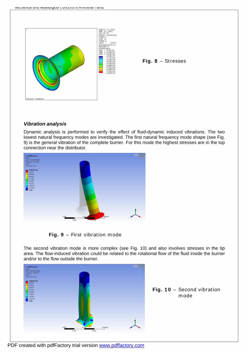
Vibration analysis Dynamic analysis is performed to verify the effect of fluid-dynamic induced vibrations. The two lowest natural frequency modes are investigated. The first natural frequency mode shape (see Fig. 9) is the general vibration of the complete burner. For this mode the highest stresses are in the top connection near the distributor.
The second vibration mode is more complex (see Fig. 10) and also involves stresses in the tip area. The flow-induced vibration could be related to the rotational flow of the fluid inside the burner and/or to the flow outside the burner.
Fig. 9 – First vibration mode
Fig. 8 – Stresses
Fig. 10 – Second vibration mode
PDF created with pdfFactory trial version www.pdffactory.com
Mechanical and Metallurgical Concerns in Ammonia Plants
The results of the analysis show that the outer fluid speed is not enough to give forces of sufficient magnitude and frequency to match the burner frequencies.
On the other side, the inner fluid rotation would induce frequencies which are significantly lower than the second vibration mode. Moreover, at this frequency, the induced forces would be of very low magnitude.
The CASALE burner is, therefore, verified in terms of thermal and vibration mechanical stresses.
Autothermal reformer (ATR) burners
Recently interest has been growing in oxygen-blown technologies for large-scale production of synthesis gas. An oxygen-blown autothermal reformer offers a simple and straightforward process layout: plot area and construction costs are reduced because of the compact design, and ultra-high capacity can easily be achieved with a single-train design.
ATR is a game-changer technology as it breaks the traditional upper capacity limit of many plants, which were economically constrained by the size of the Steam Methane Reformers. Therefore, ATR unleashes the full potential of some synthesis reactor designs (such as the CASALE Isothermal Methanol Converter) which can be scaled up to capacities thought unreachable in single-train designs a few years ago.
Oxygen-blown ATR reactors can also be employed in combination with a steam reformer (two-step reforming). The ATR is installed downstream of a steam reformer. Either the SMR is run with a high methane slip or natural gas is added to the synthesis gas stream between the steam reformer and the ATR. This arrangement can be used either for new plants or as a retrofit for old plants, in which the installation of an ATR downstream of the SMR offers a very cost-effective way to significantly increase the plant capacity with low investment, low risks and a short pay-back time.
CASALE burners are provided with a water cooling system to increase safety and to achieve a long operating life. The cooling system is designed to achieve the maximum cooling efficiency on every surface exposed to the flame, allowing long and safe operating life. The water cooling system of the CASALE burner is effective over the whole burner body, not only the tip, providing an additional level of safety and fault tolerance for every possible unexpected operating condition.
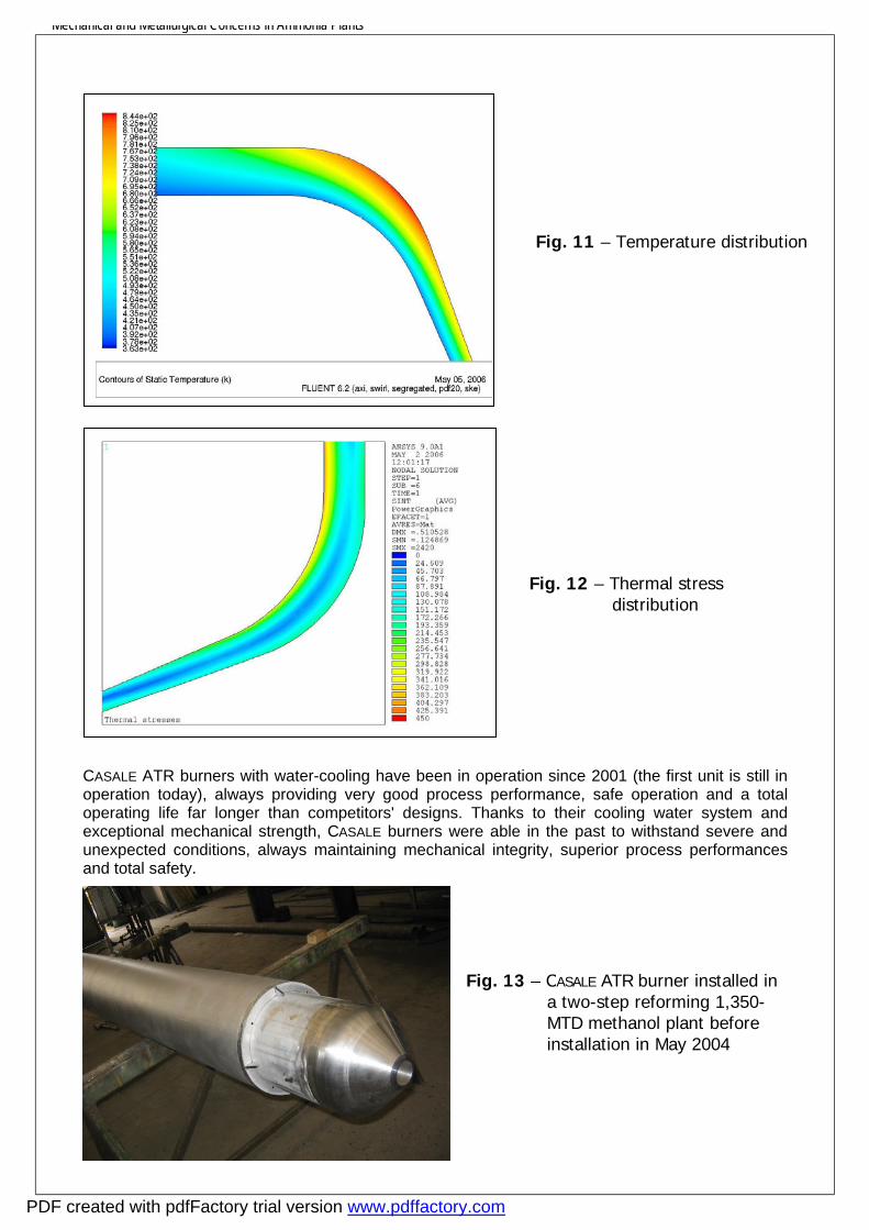
CASALE CHEMICALS relies on CFD tools in designing its burners, to simulate the flow and temperature fields inside the combustion chamber and within the burner body. Casale has then the possibility to link fluid-dynamic simulators to the finite element software to directly transfer the data from the fluid-dynamic simulation to the FEM software, specifically the temperature field. This link permits a detailed evaluation of the thermal stress and an optimal selection of the thickness required, since in high temperature application lower thickness means better heat exchange, which sometimes involve less stress and therefore longer life. Figure 11 and 12 show the steps from FLUENT fluid-dynamic simulator thermal analysis to ANSYS mechanical stresses analysis.
PDF created with pdfFactory trial version www.pdffactory.com
Mechanical and Metallurgical Concerns in Ammonia Plants
CASALE ATR burners with water-cooling have been in operation since 2001 (the first unit is still in operation today), always providing very good process performance, safe operation and a total operating life far longer than competitors' designs. Thanks to their cooling water system and exceptional mechanical strength, CASALE burners were able in the past to withstand severe and unexpected conditions, always maintaining mechanical integrity, superior process performances and total safety.
Fig. 13 – CASALE ATR burner installed in a two-step reforming 1,350-MTD methanol plant before installation in May 2004
Fig. 11 – Temperature distribution
Fig. 12 – Thermal stress distribution
PDF created with pdfFactory trial version www.pdffactory.com

Mechanical and Metallurgical Concerns in Ammonia Plants
Ammonia synthesis converter The ammonia synthesis converter and downstream heat exchanger are key items in an ammonia plant. Their reliability is essential, as a plant cannot run without them. In particular, the ammonia synthesis converter is the reactor with the longest run between catalyst changes, since it must run for 10-15 years. Ammonia catalyst, once reduced, should not come into contact with oxygen, since it is highly pyrophoric. Therefore converters should operate between catalyst changes without repair or inspection.
To achieve such a result without any impact on the safety and reliability of the plant as a whole, several aspects have to be considered; in fact, converters are subject to different metallurgical deterioration phenomena and have a complicated mechanical design with multiple catalyst beds.
Owing to the aggressive environment in which the converter operates, created by the combination of high pressure, high temperature and the particular gas composition, if high reliability is to be ensured the first aspect to be considered in the design of an ammonia synthesis converter is materials selection.
The concurrence of hydrogen-related damage (high-temperature hydrogen attack / hydrogen debonding) and nitriding is typical of the ammonia synthesis loop, particularly of the ammonia converter, where the highest temperatures and pressures coincide with a high content of hydrogen and ammonia.
Since the detrimental effect of the process environment on the materials increases in direct proportion to the temperature, the latter needs to be kept as low as possible on high-pressure parts of the process. So CASALE philosophy is based not just on the choice of appropriate materials but also on keeping these materials at a lower temperature by means of suitable thermal insulation and/or gas flushing. This concept inherently increases the safety of high-pressure parts.
The ammonia converter pressure vessel operates at a much lower temperature than the internals, since is flushed with low-temperature inlet gas, while it is protected from the high-temperature sections by the internal cartridge. Therefore, in accordance with API standard 941, ferritic materials such as carbon steel or chrome-moly steels are generally used. But CASALE has set 1 ¼ Cr ½ Mo steel as its minimum requirement in every case, even if not mandatory according to the API standard, because of its superior reliability in hydrogen service in comparison with carbon and moly steels.
Since the ferritic components of hot-working pressurized components (typically the outlet nozzle and the start-up nozzle) suffer from nitriding, a designer can consider overlay welding those parts with austenitic materials or high-nickel alloys. However this solution does not protect against hydrogen debonding. For this reason, CASALE provides for thermally insulating the hot vessel regions rather than cladding them. The insulation consists of an Inconel liner filled with insulating materials (e.g. ceramic fibre). The insulation is easily accessible, easy to inspect and simple to replace.
Fig. 14 – Same burner as in Fig 13 during a periodic turnaround. The liquid penetrant test shows no evidence of cracks or damage due to thermal fatigue
PDF created with pdfFactory trial version www.pdffactory.com

Mechanical and Metallurgical Concerns in Ammonia Plants
In three recent cases, a single-bed additional reactor placed in series with the main reactor, which was designed as a hot wall shell, suffered from weld cracking on the girth weld between shell and head.
To preserve the existing vessel from further damage caused by the high gas temperature (370°C according to the original design), CASALE developed a layout with cold flushing of the vessel internal wall. This solution allows the additional reactor to be kept on line. The flushing is performed by a gas stream taken from the shell-side outlet of the gas-gas exchanger.
The new cartridge, of axial-radial design, has been developed by CASALE in such a way that it can be installed directly in the field through the central top opening, without touching the existing pressure vessel.
The ammonia converter internals are exposed to the highest temperature and, therefore, are the elements where the combined effect of hydrogen and ammonia is strongest.
Experience has been acquired in the design of more than 200 ammonia reactors all around the world.
The use of AISI 321 stainless steel for the internals of ammonia converters is preferable compared to other stainless steels since is stabilized with titanium. In this way there is no risk of carbide precipitation (causing embrittlement of the materials in hydrogen service) which, in contrast, is possible for grades 304 or 316.
For thin elements, where stainless steel cannot be used because the thickness of the component is comparable to that of the nitrided layer, it is necessary to adopt Inconel Alloy 600, which is not susceptible to the problem. Inconel 600 is also advised for interchanger tubes working above a critical temperature (450 °C).
All the expansion joints bellows (including the ‘cold’ ones, so as to avoid possible mistakes) are in Inconel alloy 600.
Synloop heat exchanger downstream the ammonia converter As already said in the previous chapter, the synthesis loop heat exchangers located downstream the ammonia reactor are key items in ammonia plants. They are subject to the same concerns as the ammonia reactor, especially the first exchanger after the reactor outlet.
To make best use of the high converter gas outlet temperature, this item is usually either a boiler or a boiler feed water pre-heater.
In the CASALE standard design this equipment is directly connected to the converter, thus avoiding the need for high-pressure, high-temperature piping, which is a habitual source of trouble and leakage, and saving material and pressure drop.
The disposition of the exchanger itself (for example, whether the gas is on the shell side or the tube side) depends on the plant configuration. Gas tube side is used for kettle-type or natural-circulation boilers. One boiler/heat exchanger manufacturer has developed its own specific design for this type of exchanger, which has been used by CASALE in the past and still is when considered beneficial.
CASALE has also developed its own design, using fountain-type U-tubes, in which the tubes are arranged with their elbows aligned radially in the pressure shell instead of parallel to each other, as in a conventional U-tube exchanger. Gas from the converter enters the inner chamber of a concentric inlet/outlet box (the “hot box”) and passes along the tube legs that are closest to the axis of the boiler, returning along the legs that are closest to the pressure shell to the annular outer chamber outside the hot box. In this way no part of the pressure-retaining wall of the gas channel is exposed to the hottest gases.
Insulated ferrules protect the inlet tubes, keeping the temperature difference between the hot and cold areas of the tube sheet lower.
PDF created with pdfFactory trial version www.pdffactory.com

Mechanical and Metallurgical Concerns in Ammonia Plants
With this flow pattern, thermal stresses on the tube sheet are minimized. In particular, thanks to the full axial symmetry (the cold zone is the external annulus and the hot zone is the central core), the thermal gradient makes the tube sheet subject to compression but not to shear. Thus, in comparison with the traditional design, it is possible to increase the maximum ΔT between inlet and outlet with consequent improvement in efficiency or in reliability.
The fountain U-tube design overcomes the disadvantage of the fixed-tube sheet type of boiler, which is subject to failure in the event of upsets on the water side and is anyway more vulnerable to shut-down and start-up cycles, as well as the disadvantage of standard U-tube designs, where half of tube sheet / inlet channel is at the gas inlet temperature and the other part is at the outlet gas temperature. To an extent that depends on the dimensions and thickness of the tube sheet, this abrupt change in temperature will induce high thermal stresses that can result in failure of the tube sheet in the long term.
In addition to the advantages of this type of exchanger described above, the hot box, dummy tube sheet, specially-designed ferrules and the use of internal bore welding (IBW) contribute to keeping the tubes themselves, the tube sheet and the tube-to-tube sheet welds well below the nitriding temperature. An Inconel layer is in any case provided on the tube sheet to permit easy plugging of leaking tubes. It should be noted that tube plugging in a U-tube exchanger does not affect other tubes, as in fixed head type.
The gas shell side is used for forced-circulation boilers or boiler feed water pre-heaters.
In this case CASALE’s design adopts an internal shroud, which protects the pressure shell from the hot process gas. The colder outlet gas flows outside the shroud, cooling the exchanger shell. The only ferritic parts in contact with the hot gas are the tubes, which are kept cold by the boiler feed water.
Fig. 18 – Boiler with high-temperature gas in shell side
When a steam superheater is installed downstream the ammonia converter, a different design is selected. In this case the steam is not able to keep the tube temperature below the nitriding range,
Fig. 17 – Boiler with high-temperature gas in tube side
PDF created with pdfFactory trial version www.pdffactory.com

Mechanical and Metallurgical Concerns in Ammonia Plants
therefore austenitic tubes must be used. These materials are susceptible to stress corrosion cracking in a high-temperature steam atmosphere. For that reason, special nickel alloys such as Inconel 690 are used. It is also essential to design the shell side to avoid dead zones, to prevent impingement of water drops on the tubes, and to promote homogeneous flow in the shell.
EQUIPMENT CONSTRUCTION
Equipment construction is one of the most sensitive phases, because all the advantages of a good design can be lost if the construction is not up to standard.
Defects, mistakes or incorrect procedures during construction are the first cause of equipment failure.
CASALE philosophy is to utilize only a few selected manufacturers with long experience in high-pressure equipment. These manufacturers, which continuously work with CASALE, are familiar with CASALE’s specifications and designs. In any event, well-defined procedures are supplied to the manufacturers and all the critical construction phases are monitored by experienced inspectors accustomed to this specific type of construction. Accurate tests, well beyond code requirements, are prescribed for certifying the accuracy of each specific construction.
Fig. 19 – Ammonia loop superheater
PDF created with pdfFactory trial version www.pdffactory.com

Mechanical and Metallurgical Concerns in Ammonia Plants
EQUIPMENT MAINTENANCE AND INSPECTION
The critical equipment items have to undergo continuous monitoring and testing all through their life to guarantee trouble-free operation.
CASALE equipment is typically designed keeping in mind plant overhauling every three years, considering that all the required maintenance and inspection activities are adequately performed as scheduled.
CONCLUSIONS
This paper has described some of the mechanical and metallurgical solutions that CASALE has developed for its proprietary equipment. These solutions are mainly related to safety and reliability which are always given prime consideration by CASALE during the design stages, in addition to process performance.
The design of the key equipment of ammonia plants requires deep knowledge in all engineering disciplines and, in particular, of mechanical and metallurgical aspects. CASALE, as an engineering company, has in-house specialists capable of managing in an efficient and professional way all the issues relating to mechanical aspects for plant safety and reliability.
CASALE, as a supplier of a wide range of proprietary equipment, has developed a number of solutions that best suit all requirements, be it for plant retrofitting or the design of a new plant, the reliability and safety of which have been proved in industrial use in numerous plants.
PDF created with pdfFactory trial version www.pdffactory.com