mech 4240 preliminary design review composite fiber damage ...dbeale/mech4240-50/highland pd... ·...
TRANSCRIPT

MECH 4240 Preliminary Design Review
Composite Fiber Damage Analysis Device
Corp 15 – Highland Industries
Members:
Tony Tran
Luke Riney
Gabriel Aponte (Manager)
Ryan Landry (Scribe)
Bum Suk Kim
Industrial Sponsor: Dr. David Branscomb
Technical Advisor: Dr. Roy Broughton/Dr. David Beale
Overlord: Dr. David Beale
Spring Semester – March 20, 2015

Abstract Composite fibers are currently being utilized by many industries to develop strong, yet
lightweight products that are built to last. Some fibers, such as those made from carbon, have had issues
with breakages during the unspooling and weaving processes. These breakages weaken the composite
fiber bundles, subsequently resulting in less dependable final products. The purpose of this project is to
develop a device that has the ability to pull a carbon fiber tow off of a bobbin, measure and quantify the
occurring damage of the carbon fiber tow, and then wind the tow on to another bobbin. Once this
device has been developed, the device would be used to quantify the damage done when isolating
various damage-causing issues. This testing will allow for the mitigation of tow damage, therefore
allowing for the development of a stronger, more reliable carbon fiber product in the long run. At this
point in time, a preliminary design has been developed and rendered using solid modeling techniques.
Traditional systems and design engineering techniques have been utilized to narrow down potential
design concepts and to design a device that best accomplishes the desired requirements and
functionality of the device.

Table of Contents
Abstract ......................................................................................................................................................... 2
Introduction .................................................................................................................................................. 4
Systems Engineering ..................................................................................................................................... 4
Mission Objective ...................................................................................................................................... 4
Requirements ............................................................................................................................................ 4
Architectural Design Development ........................................................................................................... 5
Early Design Concepts ........................................................................................................................... 5
Developed Designs ................................................................................................................................ 7
Preliminary Design ................................................................................................................................ 7
Concept of Operation ............................................................................................................................... 9
Validate and Verify .................................................................................................................................. 10
Interfaces ................................................................................................................................................ 10
Mission Environment .............................................................................................................................. 10
Technical Resource Budget ..................................................................................................................... 10
Risk Management ................................................................................................................................... 11
Configuration Management and Documentation .................................................................................. 12
Subsystems Design Engineering .................................................................................................................. 12
Project Management .................................................................................................................................. 13
Conclusions ................................................................................................................................................. 13

Introduction
Highland Industries uses composite fiber to develop an array of strong, flexible products in
various forms. One of the composite fibers commonly used is made from carbon, but other materials
are also utilized. A single tow of carbon fiber is made up of thousands of individual, continuous carbon
fibers. These carbon fibers are bundled together to create a high strength-to-volume product, which is a
very attractive property in many industries. When the carbon fiber tow is handled in various ways,
breakages occur along the tow, therefore weakening the end product. Breakages can occur due to a
variety of issues including tension, spooling and unspooling techniques, friction, bending fatigue, contact
with sharp edges, weaving patterns, and so on.
Therefore, the company is looking for a way to monitor the effects of these issues through the
use of a simple, yet versatile, device. This report is mainly going to identify the mission statement, the
established requirements, the preliminary design developed for accommodating the stated
requirements, and how the device is imagined to function. Other topics that will be covered in some
detail include an early estimate of the materials needed along with their costs, risks involved with
operation, and the mission environment.
Systems Engineering
Mission Objective The mission objective of this project is to develop a device that has the ability to pull a carbon
fiber tow off of a bobbin, measure and quantify the occurring damage of the carbon fiber tow, display
the results of the findings, and then wind the tow on to separate bobbin. The device needs to be
versatile enough to allow for experimentation and determination of the effects of various tow-handling
properties such as tension, tow speed, and tow routing.
Requirements The requirements of the device were broken down into system and subsystem categories. The
device was trisected into the systems of structure, data acquisition and handling, and tow management.
These requirements, as well as the systems and subsystems, were developed over the course of several
interactions between the project team and the company sponsor. These requirements reflect the
current understanding of the mission objective as they pertain to the most recent breakdown of system
functions.
System: Structure
Make the structure compact enough to transport easily
o Subsystem: Cage
Support all mountings and the enclosure
o Subsystem: Mountings
Allow components to be attached to the cage
o Subsystem: Enclosure
Contain all enclosed objects

Adhere to NEMA 12
System: Data Acquisition and Handling
o Subsystem: Damage Detection
Detect damaged fibers
Overlook undamaged fibers
o Subsystem: Quantification of Damage
Count number of damaged fibers
Quantify damage of the tow as a whole
o Subsystem: Output
Run calculations on the number and quality of damaged fibers
Output the results
Allows output of data for addition analysis
System: Tow Management
Unspool the fiber from the feed spool
Spool the fiber on the take-up spool
o Subsystem: Tow Routing
Move the tow from the feed spool to the take-up spool
Do not cause any additional damage to the fibers
o Subsystem: Tension
Measure the tension
Control the tension
o Subsystem: Feed Speed
Measure the Feed Speed
Control the Feed Speed
o Subsystem: Pitch Speed
Measure the pitch speed
Control the pitch speed
Architectural Design Development
Early Design Concepts
The very early stages of architectural development began with attempting to grasp and address
the main requirements, objectives, constraints, and overall functionality of the device. The early stages
of the conceptual design building process focused mainly on the issues of keeping tension in the tow
and tow routing. Another topic of conversation included the type of sensor to be used to detect
damage, but these discussions were not reflected in the rough sketches of the early design stage.
Early concept studies established a set of desired qualities that the device was wished to
possess. An on-campus hairiness tester manufactured by Zweigle was studied to gain an understanding
of available products. This device was not designed to test carbon fiber tows, or other composite fibers
for that matter. Once tested with a bobbin of carbon fiber, a better understanding of desired qualities
was established due to the relative failure of the machine when attempting to handle carbon fiber.
Desired qualities included:
Minimal contact points between the tow and the device
Eliminate choke points and sharp edges

Detecting damage early on in the tow-routing process
Removing broken and floating filaments from the testing area
Minimal friction
The following set of pictures illustrates some early concepts.
Figure 1 - Early concept sketches
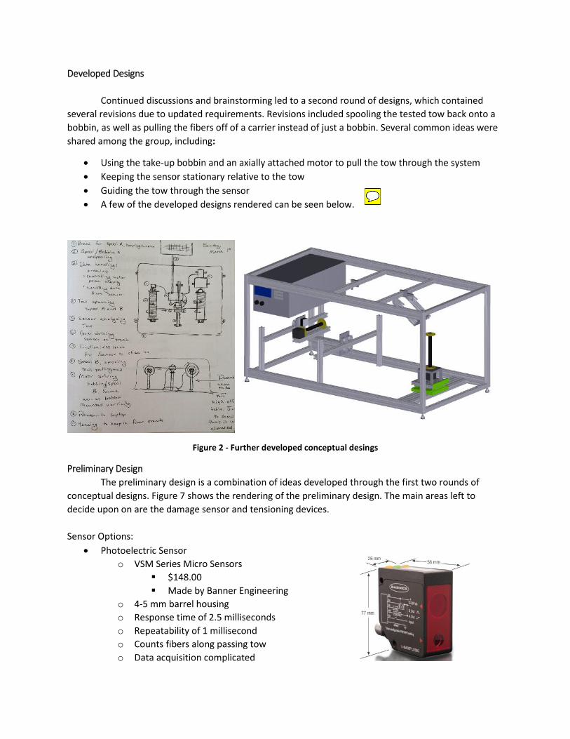
Developed Designs
Continued discussions and brainstorming led to a second round of designs, which contained
several revisions due to updated requirements. Revisions included spooling the tested tow back onto a
bobbin, as well as pulling the fibers off of a carrier instead of just a bobbin. Several common ideas were
shared among the group, including:
Using the take-up bobbin and an axially attached motor to pull the tow through the system
Keeping the sensor stationary relative to the tow
Guiding the tow through the sensor
A few of the developed designs rendered can be seen below.
Figure 2 - Further developed conceptual desings
Preliminary Design
The preliminary design is a combination of ideas developed through the first two rounds of
conceptual designs. Figure 7 shows the rendering of the preliminary design. The main areas left to
decide upon on are the damage sensor and tensioning devices.
Sensor Options:
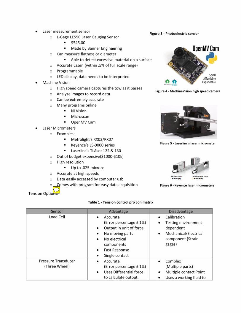
Photoelectric Sensor
o VSM Series Micro Sensors
$148.00
Made by Banner Engineering
o 4-5 mm barrel housing
o Response time of 2.5 milliseconds
o Repeatability of 1 millisecond
o Counts fibers along passing tow
o Data acquisition complicated
Laser measurement sensor
o L-Gage LE550 Laser Gauging Sensor
$545.00
Made by Banner Engineering
o Can measure flatness or diameter
Able to detect excessive material on a surface
o Accurate Laser (within .5% of full scale range)
o Programmable
o LED display, data needs to be interpreted
Machine Vision
o High speed camera captures the tow as it passes
o Analyze images to record data
o Can be extremely accurate
o Many programs online
NI Vision
Microscan
OpenMV Cam
Laser Micrometers
o Examples:
Metralight’s RX03/RX07
Keyence’s LS-9000 series
Laserlinc’s TLAser 122 & 130
o Out of budget expensive($1000-$10k)
o High resolution
Up to .025 microns
o Accurate at high speeds
o Data easily accessed by computer usb
o Comes with program for easy data acquisition
Tension Options:
Table 1 - Tension control pro con matrix
Sensor Advantage Disadvantage
Load Cell Accurate (Error percentage ± 1%)
Output in unit of force
No moving parts
No electrical components
Fast Response
Single contact
Calibration
Testing environment dependent
Mechanical/Electrical component (Strain gages)
Pressure Transducer (Three Wheel)
Accurate (Error percentage ± 1%)
Uses Differential force to calculate output.
Complex (Multiple parts)
Multiple contact Point
Uses a working fluid to
Figure 3 - Photoelectric sensor
Figure 4 - MachineVision high speed camera
Figure 5 - Laserlinc's laser micrometer
Figure 6 - Keyence laser micrometers

Fast Response
Not affected by testing environment
measure pressure and then convert to a unit of force
Ultrasonic No Contact point
Diameter Compensation
Linear reading
Not dependent on material physical appearance.
Requires a uniform flat surface
Area noise can affect readings
Sound waves could be absorbed by the material
Figure 7 - Latest preliminary design rendering
Concept of Operation The preliminary design show in Figure 7 would operate as follows:
Sensor housing
(with adjustable
boom)
Carrier
platform
with feed
bobbin
Take-up
bobbin
mount with
tracks,
stepper
actuator,
and motor.
Tow
route

1. The tow would be pulled through the entire system, from bobbin to bobbin, demonstrated by
the series of arrows labeled “Tow route.”
2. Once attached, the motor that is aligned axially with the take-up motor would be activated,
creating tension in the tow and pulling the tow through the system.
3. As the tow is being pulled, it would pass through the sensor housing and the sensor.
4. This sensor would identify breakages that are present on the tow, count the breakages, and
quantify the data.
5. The data would be presented to the user.
6. As the devices runs, the take-up bobbin would move laterally back and forth to ensure that the
bobbin is being spooled with the correct pitch. This lateral movement would be controlled by a
stepper actuator.
7. The feed bobbin and carrier would be attached to a platform that possesses the ability to
change the angle in which the tow leaves the carrier.
8. The sensor housing is attached to a boom, and the angle of that boom could be adjusted in
accordance with the tow orientation.
9. Somewhere along the tow path a tension control device would be added to measure and adjust
the tension if necessary.
Validate and Verify Validation and verification will be postponed until a final design has been established.
Developing a plan to validate and verify at this point in the preliminary design phase could be
superfluous, as many aspects of the design could change before finalization occurs.
Interfaces Many mechanical and electrical components will be coupled together through interfaces for the
designed machine. The first mechanical interface is all of the components being attached to the cage by
use of fasteners and mounting devices. This interface allows the whole machine to be transported as a
single piece. The tow routing subsystem will mechanically interface with the fibers through contact
forces to route the fibers from the feed roll to the take-up roll. Each motor and sensor will be
electronically interfaced to the electrical network be means of electrical wire. The motor will be
electronically controlled by the information from the sensors via this electrical network.
Mission Environment The environment is an indoor manufacturing plant. The work space will be air conditioned and
isolated from extreme conditions. The only disturbance would be from the vibrations of other machines
in use, which has a negligible effect on the design. The design will be compact to allow for portability
and to save space. One factor to be aware of is that the fibers from the material are conductive and can
cause issues with nearby electronics. This can be solved by containing the main functions of the machine
inside itself or a put a glass cover around the functions.
Technical Resource Budget Table 2 shows the estimated costs of two options, A and B. These two options differ only in the
sensor that would be chosen for each device. Because an initial budget was established to be $1,000.00,
research was done to find inexpensive, yet suitable sensors.

Table 2 - Estimated cost
*Total doesn’t include stepper, take up motor, or tension system
Risk Management During operation, there is little to no risk to operator and/or onlookers. Risks that need to be
monitored are mechanical and software failure. These failures are presented in the following table to
show severity and possible solutions. All failures can be visually seen during operation and data
collection.
Table 2 - Risk management matrix
Risk Title Risk Type Severity Occurrence Effect Solution
Sensor Malfunction
Mechanical, Program
1 Low Cannot acquire data
Repair or replace sensor. Debug program
Motor Malfunction
Mechanical
1 Low Operations cease Repair or replace motor
Fiber build up Environment 3 Medium Damage to tow and routing
Use of a vacuum/air blower to remove loose fibers from tow
Loose fibers affect machinery
Environment, Mechanical, Safety
2 Medium Possible machine failure
Contain fibers inside a see through cover. Use of a small vacuum or air blower
Feed angle locked up/stuck
Mechanical 4 Low Unable to test fiber tow at different angles
Find cause and remove/fix. Worst case is to buy another part
Tow leaves spool during respooling
Mechanical, Environment
2 Low Operations cease, Fibers build up inside machine
Stop operation and secure tow to bobbin before

resuming
Configuration Management and Documentation Documents and designs are saved on Dropbox for ease of use and availability for all group
members and the company sponsor. A group email is also used, identified as corp15, to communicate
between group mates, technical advisor, and company sponsor. A design notebook is also used to keep
meeting notes and ideas as the design progresses.
Subsystems Design Engineering As concept studies and development become more specific, developing subsystems require lots
of studies. First of all, it is important to find requirements for each subsystem because each subsystem
can change the whole concept of a preliminary design. After develop concept, three systems are
developed which are structure, data acquisition and handling, and tow management.
From the result of the concept development preliminary design lead subsystems development.
Starting with structure, it is important to design a device compact and light enough for portability. In
order to attach components of the system easily, the structure system used a cage-type box design.
Aluminum members were chosen for its rigid and lightweight properties. One of the requirements for
the structure system is to meet NEMA 12 enclosure requirements because of the risks associated with
floating carbon fiber filaments.
For data acquisition and handling, damage detection, quantification of damage, and output
subsystems needs to be developed. In order to detect damaged fibers and overlook undamaged fibers, a
sensor system has to be established. Photoelectric sensors, laser measurement sensors, high speed
cameras and laser micrometers are all options that can be used for fiber detection subsystem. One of
the sensors has to be chosen for easy, yet accurate counting of the number of damaged fibers.
Depending on the sensor, output methods can be number of different methods (e.g. image analysis,
machine vision programming, etc). Sensors for this type of damage detection vary in cost significantly.
The tow management system manages the tow routing, tension, feed speed and pitch speed
subsystems. The basic concept is to unwind the fiber from the feed spool and wind the fiber back on to
the take-up spool. Designing the tow routing is a very delicate process because bad tow routing can
cause unnecessary damage to the fiber while feeding it through the various components. While feeding
the fiber, tension needs to be measured in order to control feed speed and to maintain a constant
tension. Load cells, pressure transducers (three wheels), and ultrasonic sensors are all options for
tension control. There are advantages and disadvantages for each method which were shown in Table 1.
A pitch speed control system needs to be developed due to its influence on other subsystems, including
the feed speed and tension control subsystems.

Project Management
Project management for the preliminary design review was divided among the design group as it
consists of five people. A majority of the early objective understanding, research, and concept design
was done as group. Constant communication with the company sponsor and technical advisor was
needed to understand the mission objectives and further concept development.
As the design concepts became finalized, the focus of the group turned towards researching
components, specifically the hairiness and tension sensors, and other building materials. The group split
to work independently on acquiring pricing and part information and creating CAD models in
SolidWorks.
Once the preliminary design review is over, the goal of the group is to finalize the chosen design
and acquire parts and the correct sensors. Machine vision cameras will be looked into with greater
detail. Then the group will focus on researching, collecting, and testing the data given by the sensors.
Ideally, the entire design will be completed before the final review and construction can begin.
Conclusions
From the research conducted for the project, it was determined that a simple design of a cube
roughly two feet on each side is ideal for transportation as well as functionality. The cage will need to be
constructed of lightweight yet durable material so aluminum is planned to be used. Plexiglas will be
used for the enclosure to adhere to NEMA 12 and allow the user could see inside during operations. The
sensor chosen for use in the design was a photoelectric sensor due to price constraints, while still
accommodating the need for the high resolution and accuracy. Tension will be measured through means
of a load cell mounted to a pulley. A motor shall be used to spin the take-up spool to move the fibers
from the feed bobbin to the take-up bobbin, while a stepper evenly distributes the fibers across the
take-up spool. Overall the design completes all required functions and is contained within the budget.
The next steps are to finalize and dimension the design, order the parts, and begin building the machine.