measurements on the optical system of the marconi mark vii...
TRANSCRIPT

CONFIDENTIAL
RESEARCH DEPARTMENT
Measurements on the optical system of the Marconi Mark VII
Four - Plumbicon colour television camera
TECHNOLOGICAL REPORT No. T - 178
U DC 621. 397. 132 : 535. 65 1966/62
THE BRITISH BROADCASTING CORPORATION
ENGINEERING DIVISION

CONFIDENTIAL
RESEARCH DEPARTMENT
MEASUREMENTS ON THE OPTICAL SYSTEM OF THE MARCONI MARK VII FOUR* PLUMBICON COLOUR TELEVISION CAMERA
W.N. Sproson, M.A. M.K.E. Smith, K.J. Wright,
Technological Report NI). T-\ n UDe 621.397.132: 1966/62
535.65
for Head of Research Department
This Report is the property of the British Broadcasting Corporation and may not be reproduced or disclosed to a third party in any form without the written permission of the Corporation.
ThlA Report URea SI unite in ftctorrtRn~~ .tth R~8. doeument PD ~688.

Technological Report No. T-178
MEASUREMENTS ON THE OPTICAL SYSTEM OF THE MARCONI MARK VII FOUR-PLUMBICON COLOUR TELEVISION CAMERA
Section
1.
2.
3.
4.
5.
Title Page
SUMMARY . . . . . . . . . . . . . . . . . . . . . . . . . . . . . . . . . . . 1
INTRODUCTION . . . . . . . . . . . . . . . . . . . . . . . . . . . . . . . .
COLORIMETRY
2.1. The Colouring Channels ~easured at Normal Incidence 2.2. The Luminance Channel \1easured at Normal Incidence 2.3. Optical Transmission of the System at Normal Incidence 2.4. Dichroic Tilt (in the colouring channels) . 2.5. Dichroic Tilt (in the luminance channel) .
2.6. Uniformity of the Dielectric Coatings
OPTICAL PERFORMANCE
3.1. Veiling Glare Index 3.2. Optical Transfer Function
CONCLUSIONS .
REFERENCES
1
1
1 2 3 4 5 5
6
6 6
8
8
APPENDIX. . . . . . . . . . . . . . . . . . . . . . . . . . . . . . . . . .. 8
aqualizing glass block
r-----------.. : zoom or fixad: : focus : I lans I L __________ ..l
luminonca splittar
prism
colour
splitting
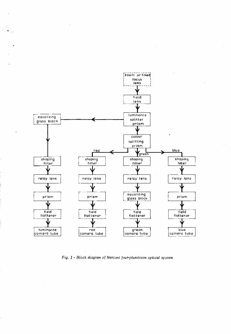
Fig. 1 - Block diagram of Marconi four-plumbicon optical system

CONFIDENTIAL
November 1966 Technological Report No. T-l78 UDe 621.397.132: 1966/62
535.65
MEASUREMENTS ON TilE OPTICAL SYSTEM OF THE MARCONI MARK VII FOUR· PLUMBICON COLOUR TELEVISION CAMERA
SUMMARY
Measurements are reported on the optical system of the Marconi four. plumbicon camera in respect of colour analysis, dichroic tilt, spectral characteristics of the luminance channel, overall optical efficiency, veiling glare index and optical transfer function.
1. INTRODUCTION
This report describes measurements on the complete optical system of a four·tube camera made for Marconi's by their sub-contractor Barr and I;)troud. The relay lenses and field lens in the system were made by Dallmeyers. The optical system uses a relay lens in each channel (luminance, red, green and blue) and gives a reduction ratio of 1'9, viz. the ratio of the image orthicon format to the plumbicon format. The prime image formed by either a zoom lens or a fixed focus lens is formed at a field lens and is re-imaged by the relay system. The luminance/chrominance and R.G.B. colour splitting is achieved in the frotH conjugate of the relay· lens. The colour-spli tting pri sm block is similar to that used by Philips.1 A block schematic diagram of the complete optical system is shown in Fig. 1.
The measurements will be described under the main headings of colorimetry and optical performance.
2. COLORIMETRY
2.1. The Colouring Channels Measured at Normal Incidence
Using a modified Unicam SPSOO spectrophotometer, measurements were made of the transmission characteristics of the red, green and blue channels at normal incidence (corresponding to centre of field) in horizontal and vertical polarizations for a range of wavelengths 400 to 700 nm. J\s directly measured, transmission is given relative to a single ophthalmic lens but thi s has been corrected for in
50
40
~30 c o
·Vi III
·E20 III c o !:;
10
,..cl 00
bIU<l~
I .~
f V
_. gr~n
l ~~ P \~
.If' ~d
I ~ ,x:'" -x- ....x- -x-.,
\ x I
r\ 1 ~\ /,i , J \ (f
~I ~ 5 0
WQv<ll<lngth. nm 600 700
Fig. 2 - Colouring channels Spectral transmission characteristics at normal incidence --x ... - horizontal polarization -0- vertical polarization
Fig. 2. The transmission factor includes the effect of all optical components in the path, i.e. prism blocks, dielectric spli tting and shaping filters, the relay lens and field lens. The system is relatively free from troublesome effects due to polarization. If any trouble were found, it could be removed by the use of a quarter-wave plate,2 but it is thought unlikely that thi s will be needed.
To evaluate the effective sensitivities of the colouring channels, the optical transmissions were multiplied (wavelength by wavelength) by the sensi- .. tivity of the appropriate plumbicon tube and the relative energy curve of the studio illuminant

2
024~-+--~--+-~-I~--+---r--+--~--+-~--~~i---t--i---r--+-~
022~-+--~--+-~~~--+---r--+--~~+-~--~~+---t--+---r--+-~
~0201~~~-+--~--~~~~---+--~~+-+-~~--+T--~--+---t-~---+--~ ,~ c: ~O'18~-4---+--~--~--~-+---+--~~+-~r--i~~--~--+---r--i---r~ >. L. a ~016~~---+--~~P---~-+---+--~~+-__ t--+~~--~r-+---r--+--~~ ii L. 2 0 '14~~--+--+---tH--+--H--+--HL--+----1I--t-lf-+--+i-+--t--t--~------I
Of ell
g 0,12 f-~---+-+-l-+--+--+t---+---tf-+--ft--t~-+--+++---r--i---+~ a. If)
~ O'10~~f---+--~-I-+--~--+t---+--f---+---~~-t--+--+--t+---t--t---+~
~O'08I----l---+--+l---t-t--+--t--It----+-r\'t-~ -t+-t-----t--tt-r--+--r----j
~ 0061---+----+--tJJ--+--+----'t--+-"/f+---+-t------o~HI'-----1r--t------t1r--r---t--r--j !J \
O,041---+--+----j/Bl--+--+--a~~,~ --+-', 'It-l-+-+--+----\\fJt--t--t--t-'\-',-+---+-t----1
0021---+--.L--l~--rl'--t--+-+I;-\'.~;-.I-J-V+-+---+-t-.;-,:~-j' ".~:---t--t----1ft\~-,-, .. -t---t---i ~60 400 440 480 520 560 600 640 680
WOV<lI<lngth, nm
Fig. 3 - Response of colouring channels in 3000° K illuminant Normalised areas
---- Marconi camera ---- BBC specification
50
40
~30
720
(30000 K). The result is plotted in Fig. 3 together with the "optimum positive only" specification issued by the BBC (TV /1'26 and TV 1148). The only respect in which the system is not close to the specification is the relative height of the bluegreen cro ssover. Other important parameters are within the specification limits (see Table 1).
c: o '0;
_v- I!-)( ......
2.2. The Luminance Channel Measured at Normal Incidence
The spectral transmission characteristic of the luminance channel is shown in Fig. 4 for the two mutually perpendicular polarizations. As with two colouring channel s, the effect of the plane of polarization is relatively slight and can probably be ignored in practice. The effective response of the luminance channel is obtained by mUltiplying
peak wavelengths red green blue nm nm nm
TV/126 and TV/148* 607'15 542±5 456±5
Marconi 4-P Optical 604 542 453 System
III
'E20 ~ o !::
';-~
,x' k- ...0-J,...o- "'" )-D'
10 ~
1\. .AJt" ~ o 400 500 600 700
waV<lI<lngth. nm
Fig. 4 - Spectral transmission of luminance channel at normal incidence
-..,x-- horizontal polarization -<>- vertical polarization
TABLE 1
crossover wavelengths cros sover ordinates red-green blue-green red-green blue-green
nm nm nm nm
577±5 494±5 8% to 15% 3% to 8%
582 496 11'3% 1'3%
'" Allowance has been made for 30000 K illuminant in the figures quoted in Table 1.

0-14
0-12
., -E 0-10 ::I
» 'c '-:B 0-08 'c ~
ell OIl C o 0.0-06 OIl ell '-ell -~ 00-04 C; '-
0-02
o 360
... ~~ 400 440
/
tJ r/·
j 11/
llv /'/,'
! 'f/ llJ 7
} ,/1 V- '"
480 520
3
IJ'~
V~ [/ f\\ , \\ r\\ , ,~ , .
1\\' 1\ ~,
'\ ~\ \ \~ \
\ \'I \ .~ \ \:'\\~ \' , --.- ----I- 1\ '"
'\ ~~ .:.."'::: 1-.-560 600 640 680 720
WOV<2I<2ngth, nm
Fig. 5 - H.esponse of luminance channel in 3000° K illuminant and in Illuminant C using plumbicon tube type 55875
Normalised areas (p- Luminance channel response weighted by E:Jooo -- )(-- Luminance channel weighted by Ec
---_--Photopic response weighted by Illuminant C --- Photopic response weighted by 30000 K illuminant
the optical characteristic (mean value) by the response characteristic of the plumbicon tube and the spectral energy di strib.ution of a 30000 K illuminant. The result is plotted in Fig. 5.* The photopic curve weighted by a 30000 K illuminant is also shown: it will be seen that there is an excess of output in the blue-green and green regions (470 to 560 nm) and a deficiency in the red region (570 to 700 nm). In view of the fact that the colour picture is observed with a white point corresponding to Illuminant C, it might well be argued that (for a studio camera) it is better for the luminance respons e of the camera to resemble that of the photopic curve weighted by Illuminant C. Thi s curve is also shown in Fig. 5 and happens to give a closer fit to the experimental curve. This argument does not apply to the four-tube camera when used in natural daylight.
If the processing of the luminance, red, green and blue signals is in accordance with "Livingstone Case 2", deficiences in the luminance response in the red and blue spectral regions can be used to offset the increased luminance which otherwise results for highly saturated and blue colours. 3 A
... This characteristic includes a luminance shaping filter (see Appendix).
deficiency plumbicon understood design.
in the red is inevitable with existing tubes: the deficiency in the blue is to be an intentio nal feature of the
2.3. Optical Transmission of the System at Normal Incidence
The transmi s sions quoted in Sections 2.1 and 2.2 may be added to produce the curve (a) given in Fig. 6: this shows the overall optical transmission factor at each wavelength. The transmissions at the peak wavelengths of the colouring channel s are somewhat low,** particularly in the blue channel where less than 25% of the incident light reaches the photocathode of the blue tube. -At 545 nm (peak of the green channel) the transmission is just over 50%. The transmission in the red channel must be judged in the region of 600 to 610 nm where a figure of about 42% is achieved: at 650 nm a transmission of nearly 50% is achieved but this is of no direct value because the standard plumbicon tube has little or no response at 650 nm. It should be noted that, due to the fundamental requirements of colour analysi s, only the peaks of curve (a) could approach .. 100 percent .
...... See Appendix for detailed measurements on individual optical elements.

4
100
90
80
70
60 . .. c o 'Vi ,~50 E III C o '+'
40
30
20
10
/-
I I
I I
,"" J \I
/ I I
./
", \
1\ I I
\ I , I \ \
I I I I
\ I J - 1/ I
J I
A II1 , I L
1\ // '" ,-blulZ " r1 \' I\..
~T I ,,"" '- ,
,,-"" thrlZlZ -tublZ
Plumbicon -
/
/ " ....
I ..- ~
:,..,. (a)
\ .",,-~ total j
~ A \ J
~ Marconi four-tublZ
"' \ J /, Plumbicon - r---
\ I \grlZlZn / I I
rlZd
,/---~ -luminanclZ , .' /
'" "t, ,
/ ,
\ I \ I ' ,
1\ I
,\ o 360 400 440 480 520 560 600 640 680 720
wavlZllZngth,nm
Fig. 6 - Overall optical transmission of four plumbicon optical system Luminance, red, green and blue individual channels also shown
On the ba si s of the measured optical transmission and a knowledge of the transmission of Varotal V zoom lens it is possible to estimate the sensi ti vi ty of the camera. Using the manufacturer's minimum guaranteed figure for the sensitivity of the plumbicon tube,* it is deduced that an incident light level of 206 lumens per square ft** on to the standard E.I.A. chart will give a signal-to-noi se ratio of 38 dB in the luminance channel on white and signal currents in the R.G.B. colouring channels of 0'02, 0'11 and 0'03 fLA respectively. The head amplifier in the luminance channel is assumed to gi ve 45 dB signal-to-noi se ratio for a signal current of 0'3 fL A. The zoom lens is assumed to be set to an aperture of fl8 giving an effective aperture of fl4'2 in the plumbicon channels and this gives the standard depth of field assumed in calculations of this type.
* 325 fJ-A per lumen (2850°K) for a supply of 25 tubes.
** Direct measurement has given a figure of 215 lumens per sq. ft: see Reference 3.
A corresponding figure for a three-tube plumbicon camera has been evaluated at about 118 lumens per sq. ft. The difference in the sensitivities is largely caused by different utilizations of the incident light flux in the colour splitting blocks and is not necessarily a direct consequence of the four-tube versus the three-tube approach to the colour camera problem.
2.4. Di chroic Tilt (in the colouring channel s)
The reflection/transmi ssion characteri stics of a multilayer dielectric filter are a function of the angle of incidence and it is therefore difficult to design a colour splitting system which is entirely free from dichroic tilt. 4 In the present case a variation of ±5'6° on to the prism splitting block is required to cover the picture height. The effect of such a change in angle has been measured in the spectrophotometer and the consequent changes in output in the R, G and B channels calculated. The

1 1
~ '\
V
09 -6
~
" "t ~ "-
'" r... t'--~
blue
V I-""' ""- green ~
V I'... red_
~ t--
,,~
'" -3 0 3 6
angle of incidence,degrees
Fig. 7 - Variation in output of red, green and blue channels with vertical angle of incidence using plumbicon type 55875 in the red and green channels
and type 558758 in the blue channel Illuminant 30000 K
result is shown in Fig. 7. The calculated changes in the chromati ci ty of the white point are equi valent to about 3 jnds from top to bottom of the picture. This is definitely in excess of the threshold of percepti bili ty 4 and wi 11 need to be corrected.
2.5. Dichroic Tilt (in the luminance channel)
The transmission characteristic of the luminance channel is al so a function of the angle of incidence and the result plotted in Fig. 3 applies to normal incidence only. Because of the different orientation of the luminance/ chrominance splitting block, it is necessary to consider an angle of ±7'5° (corresponding to picture width) in order to evaluate
... :> n ... :> o
1·2
1·1
1·0
<>I 0·9 >
·
... o .. I... ()....-
0·8
0·7
06 -8
"---
L /
./ V
./ ~ ~
-6 -4 -2
5
this effect. The calculated results for a neutral grey (based on measurements taken on the spectrophotometer) are plotted in Fig. 8. The subjective effect of this luminance tilt is unknown: the eye is fairly tolerant to symmetrical smooth changes of brightness such as occur in lens vignetting and it is possible that the asymmetrical variation shown in Fig. 8 will not be perceptible .. Only a practical test can determine the position with certainty.
2.6. Uniformity of the Dielectric Coatings
Dichroic tilt due to change in angle of incidence is a fundamental effect but in practice there may be an additional source of colour error due to non-uniformity of the dielectric coatings. This may add to or subtract from the fundamental effect. An attempt was made to measure uniformity of the whole system by laterally displacing the system (less its field lens) with respect to a small beam of light emerging from the spectrophotometer and measuring the change in output, This is not an ideal way of performing thi s measurement since the vignetting of the relay lens is also included but it did not appear to be an easy matter to remove the two prism blocks and take measurements on these alone. The results will not be quoted in detail since their reliability is very questionable: the R, G and B output curves versus position follow one another fairly closely but there is an asymmetry in the shape of the mean curve which cannot be due to the vignetting of the lens. In view of the need for high precision in this type of measurement, it is felt that no useful comment can be made about uniformity on the basis of the present measurements.
--
~ ~ ............ --~-~-
./'" /" .~
\
\ 1 \
o 2 4 6 8 angle of incidence,degrees
Fig. 8 - Variation of output of luminance channel with horizontal angle of incidence

6
3. OPTICAL PERFORMANCE
3.1. Veiling Glare Index
Two measurements were made of veiling glare index: in the first case, the veiling glare index of the complete sy stem including a Varotal V lens was determined; in the second case the Varotal V was used to correctly illuminate the Marconi optical system but a small black square was afixed to the centre of the front surface of the triplet field lens and the veiling glare of the Marconi optical system alone was measured.
The standard method of determining veiling glareS was used in the first case. Care was taken to ensure that the first image of the test object was formed at the front surface of the field lens and that the zoom lens was correctly adjusted for back working di stance and focus control. This measurement was taken at two apertures of the Varotal V lens (viz. fl4 and fl8) and for the luminance and green colouring channels. These measurements
• were repeated wi th the black spot on the fi eld lens for the same apertures and channels. Additionally, the vei ling gl are index of the Varotal V lens alone was determined. This in fact was appreciably higher than the values previously measured for thi s type of lens. 6 Veiling glare indices are not additive so that the veiling glare of the complete system (Marconi four plumbicon and Varotal V) is less than the sum of the indices for the two separate parts. In the case of the luminance channel, it was not possible to measure the index to red, green and blue lights because there was insufficient light flux. The results are shown in Table 2.
Aperture fI 4
TAHLE 2 Veiling (jlare Indices
Lighting Varotal V Marconi Complete only 4-P System
only
Tungsten white 3'0'70 3'6% 4'7%
Red 2'45% Green 3'4% 3'6% 5'5% Blue 3'8%
Aperture fl8
Tungsten white 3'0% 5'1% 6'0%
Red 2'45% Green 3'4% 5'1% 6'1% Blue 3'8%
4-P Channel
luminance
green
luminance
green
The magnitude of the veiling glare indices are fairly high although they are not unexpected in view of the large number of surfaces in the system (24 in the luminance channel and 26 to 29 in the colouring channels). One advantage which thi s system possesses is not revealed by our method of testing, If a light source is just outside the field of view, any light flux from this source will be stopped by the rectangular mask at the field lens, although thi s does not reduce the flare produced by the zoom lens under these circumstances.
The system examined was new and the surfaces were reasonably clean. It is to be hoped that the sealing of the optical system is good, otherwise the veiling glare index will certainly increase as dust settles on the exposed surfaces.
3.2. Optical Transfer Function
The physical construction of the Marconi fourplumbicon optical sy stem does not make the measurement of optical transfer function (o,t,f.) easy. In particular, the metal base plate extends for many inches behind the plane of the final optical image and thi s make sour normar method of measurement impos sible. An addi tional relay sy stem was therefore used to transfer the image by about 4Y2 inches (115mms): two microscope objectives were mounted at the ends of a tube of appropriate length and thi s in turn was mounted on to the usual microscope objective. This additional relay system was tested to see whether it produced any additional impairment in a known ima'ge resulting from an fl2 lens. Over the spati al frequency range 0 to 20 cycles per mm no additional impairment was measurable, Because of the large forward extension caused by the microscope relay system, too much mechanical instability resulted to use the normal method of measurement (sine wave analyser).7 As an alternative, the spread function was recorded and the Fourier transform determined with the aid of a desk calculating machine. The results are shown in Fig. 9: a reasonably high value of modulation transfer factor is obtained at the video cut-off frequency. Varotal V does not give a perfect image: Fig, 9 shows the combined effect of the aberrations of both optical systems. Fig. 10 shows the performance of the Varotal V alone.
The sharpness impairment of the image resulting from a Varotal V and the Marconi four-plumbicon system is evaluated at about -1'58 limens. 8 Varotal V alone (at the same focal length as used in the full system) gives a sharpness of about -1'0 limens, The lenses designed for use with a three-plumbicon camera give sharpness impairments of about -1'6 limens at the corresponding focal length. It is thus seen that the four-plumbicon system gives about the same performance as the three-plumbicon system in respect of sharpness. From a more detailed inspection of the results it may be shown that greater uniformity of o.t.f. over the field oc'Curs in the case of the four-plumbicon system.

1·0 ~ ~ b
~ ~~~ ~ ~ :" ......
'\ ~ ~ .......
\ l'-~ ...... C, "-
0·8
"'- ~ ~, " ['.., ~
aXis,s (sagittal) t--
" I I 1 0·7
........... ~ 0'8 fi .. ld ••
r-.... , 0·8 fiQld. t
'""-l QXis.t (tang .. ntial)-0·4 fi .. ld ••
06
0·4 fi .. ld.t
0'5
0·4
0'3
0·2
01
o o 2 3 4 5 6 7 8
froquClncy, MHz
Fig. 9 - Modulation transfer functions of complete optical system including a Varotal V lens at full aperture Test object at infinity
1'0
0·8
0·7
06
0'5
0'4
0·3
0'2
0·1
o o
-.....~ ~
1'..'
2
,,~ ~ ~ I'\. .... "\~ ~
t\. '" ....... ~ ~ QXIS,S (sagittal)
I\.. ..... , r-.....
Qxis, t (tangantial .... 0·4 filZld,s
~'I..... °j""lt -" ~
"\ 0,8 fi .. ld ••
'-"I\.. ~
"' 08 fi<zld,t
_. r-
3 4 5 6 7 8 frllQuczncy, MHz
7
fig. 10 - Modulation transfer functions of Varotal V No. 698353 at 120 mm focal length and an aperture of fl4 Test object at infinity

8
4. CONCLUSIONS
The colorimetri c performance of the colouring channels of the Marconi four-plumbicon optical system is very close to that demanded by the BBC Specifications TV/126 and TV/148. The separate luminance channel has a spectral response fairly close to the photopic curve and use has been made of the deficiencies in the red and blue parts of the spectrum to improve the colour accuracy using "Livingstone Case 2" signal processing. Dichroic tilt is estimated to be appreciably above the threshold value and will need to be corrected. Overall optical efficiency is slightly disappointing even allowing for the complexity of the optical system and this will necessitate higher lighting levels in the studio. The sharpness of the optical image is comparable wi th that produced by other (three-tube) cameras. Veiling glare indices are rather high (5 to 6%) but not unduly so in vi ew of the large number of surfaces in a complete system (including a zoom lens).
5. REFERENCES
1. DE LANG, H.and BOUWHUlS, G. 1963. Colour separation in colour television cameras, Philips tech.Rev., 1962163, 24, 9, pp. 263 - 271.
2. Colour television cameras: the reduction of errors due to polarization. Research Department Technical Memorandum No. T-1057.
3. A comparison between Marconi Mark VII and Philips' PC60 colour television cameras. Research Department Technical Memorandum No. T-1091.
4. Dichroic tilt in colour television cameras. Research Department Technical Memorandum No. T-1089.
5. Secondary flare in optical lenses. Research Department Report No. T-076 and BBC Engng Mongr., 1961, No. 36.
6. Varotal V : A 10 to 1 zoom lens for the image orthicon format (No. 617566). Research Department Report No. T-112, 1963/36.
7. New methods of lens testing and measurement. BBC Engng Mongr., 1963, No. 50.
8. New equipment and methods for the evaluation of the performance of lenses for television. BBC Engng Mongr., 1957, No. 15.
9. Use of a linear matrix to modify the colour analysis characteristics of a colour camera. Research Department Report No. T-157, 1965/50.
APPENDIX
Section 2.3 comments on the overall opti cal efficiency of the Marconi four-plumbicon optical system. Because of the importance of optical efficiency in relation to sensitivity, it was felt desirable to examine the individual elements of the system to ascertain precisely how light flux is lost (or absorbed). These additional measurements were made possible by the co-operation of Marconi's who sent one of their staff to take the optical system to pieces.
The following measurements were made on the Unicam spectrophotometer: (In all cases the light flux was incident normal to the optical elemt'!nt and a quarter wave plate was inserted at the exit slit of the spectrophotometer to overcome polarization effects).
1. Output of luminance channel of luminance splitter at 640 nm.
2. Output of colouring channel s of luminance splitter over the range 400 to 660 nm.
3. Output of red channel of colour spli tter over the range 560 to 650 nm.
4. Output of green channel of colour splitter over the range 460 to 620 nm.
5. Output of blue channel of colour splitter over the range 400 to 520 nm.
6. Luminance shaping filter over the range 400 to 660 nm.
7. Red shaping filter ove r the range 400 to 650 nm.
8. Gre'en shaping filter over the range 400 to 650 nm.
9. Blue shaping filter over the range 400 to 650 nm.
10. Relay lens plus glass block (green channel) at 450, 550 and 650 nm.
11. Relay lens of each channel at 450, 550, 600 and 650 nm.
12. Equalising glass block In luminance channel at 450, 550 and 650 nm.
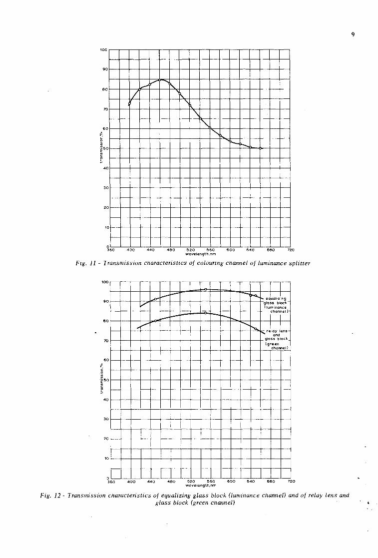
The detai led results of items 2 to 10 are plotted in Figures 11 to 15.
100
90
80
70
60
... ~ o iii
~50 ., ~
~ 40
30
20
10
o 360
./ v /
400 440
....... , "1",,-
\
\
i" ~
'-r......
480 520 560 600 640 680 720 wovczlangth. nm
Fig. 11 - Transmission characteristics of colouring channel of luminance splitter
100
QO
80
70
60
40
30
20
10
o 360
..-0--,/'
... "..,..
400 440
,,-r--
~ -
~-.
480
~
--....., r--..
520 560 WQVtZl(lngth,nm
600
-...., ~ I' aJuolizi n9
glass block ( luminance
channQI)
I I .......... ~ r-- rJlay Lns
and glass block (gra<ln chom~
-
I
640 680 tJ
720
Fig. 12 - Transmission characteristics of equalizing glass block (luminance channel) and of relay lens and glass block (green channel)
9

10
lOO
gO
80
70
60
50
40
30
20
10
o 360
j f\;~ I1 1
'J"
f I1
\J j ,
"""11\.. IJ '1~
400 440 480
A J
grczczn
j tfod I V
L / /
\ f
i , ~ \
r"o'[i J ~ \ IJ \ \ I" --
520 !l60 600 640 680 no wQvelczngth,nm
Fig. 13 - 1 ransmission characteristics of colour splitting block over relevant spectral regions
100
gO
80
70
--60 --"
50
40
30
r----
20
10
o 360
I
, I -t
"-
I
, i
-t~
i I
c-. i 1 ~
J ~~l-d-
- ---'----400 440
/'" I,.--""
V jlumtnancQ J~gr •• n
11 \ --
I1
-_._. --- ~ 1\ 1 1 \
~IUQ
\ ~ \ \
1\ I \11 rI ~
480 520 560 wavczlllngth, nm
V , "--
1.d --- _0_- --- "-- -- ""-
---
-"
------ r--"-r--- --"
-" "-- - --- .. -~ "-
1 --r-\ , r--- r--- --- --_. -----
f\, --
-----~ 600 640 680 720
Fig. 14 - TransmissIOn characteristics uf slzaping filters used in the Marcuni fuur-plumbicon optical system

11
100
...... 00 ...
~..: ~ t- ... ::-." r--... ---::: r':"" - .... 1'0-. r~d
~ ",. /1./ i"- t ..... .> 'X 9r~ln_+---l/ ~~ lu~inancc: blu~-~
80
70
60
40
3 0
2 0
0
0 360 400
V /
440 480 520 560 wavczlangth,nm
600 640
It is helpful to cons truct a "balance sheet" showing the transmi ssion factor of individual elements at the peak wavelengths of the luminance, red, green and blue channels. This is shown in Table 3. The product of the five elements is quoted
TABLE 3
1 ransmission Factors of the
680 720
Fig. 15 - Transmission characteristics of a typical set of relay lenses
These lenses constitute a typical set, but they are not the actual lenses used
in Optical System No. 56
and also the measurement on the complete optical system as given in the main text. The agreement is reasonable for the luminance, red and green channels, especially in view of the fact that the individual elements were cleaned prior to measurement.
Marconi. Four-Plumbicon Optical System No. 56
Luminance Red channel channel
at at 640 nm 640 nm
Luminance spli tter 0-41 0-503
Relay lens + block 0'76 0-805
Colour splitter 0-76
Shapi ng filter 0-954 0-951
Field lens 0-942 0-942
Glass block 0-930 -- --
Product 0-260 0-276 -- ---
Direct measurement on complete system 0-239 0-253
Green channel
at 550 nm
0-654
0-84
0-83
0-845
0-942
--0-363 ---
0-345
Blue channel
at 450 nm
0-835
0-80
0-77
0-592
0-933
--0-284 ---
0-225
Note: The red channel (and luminance channel) are quoted at 640 nm because both channels reach an approximately constant value of transmission at this wavelength and this determines the luminance/chrominance. splitting ratio. In terms of the red channel, the transmission at 600 to 605 nm is more relevant, as stated in Section 2.3.
12
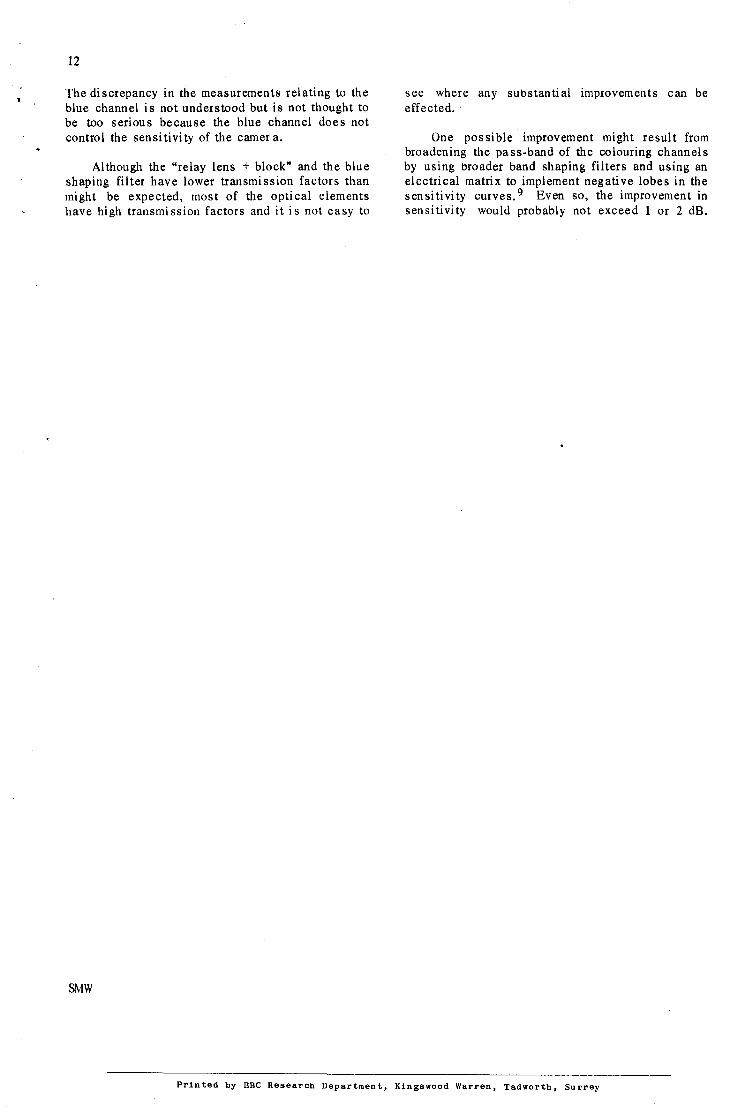
The di screpancy in the measurements relating to the blue channel is not understood but is not thought to be too serious because the blue channel doe s not control the sensi tivi ty of the camer a.
Although the "relay lens + block" and the blue shaping filter have lower transmission factors than might be expected, most of the optical elements have high transmission factors and it is not easy to
SMW
see where any substantial improvements can be effected.
One pos si ble improvement might result from broadening the pass-band of the colouring channels by using broader band shaping filters and using an electrical matrix to implement negati ve lobes in the sensitivity curves. 9 Even so, the improvement in sensitivity would probably not exceed 1 or 2 dB.
Printed by BBC Research Department, Kingswood Warren, Tadworth, Surrey