measurements of the 60 ghz ue to enb channel for small
TRANSCRIPT

Measurements of the 60 GHz UE to eNB Channel for Small Cell Deployments
Yoo, S. K., Cotton, S., Heath, R. W. & Chun, Y. J.
Published PDF deposited in Coventry University’s Repository
Original citation: Yoo, SK, Cotton, S, Heath, RW & Chun, YJ 2017, 'Measurements of the 60 GHz UE to eNB Channel for Small Cell Deployments' IEEE Wireless Communications Letters, vol. 6, no. 2, pp. 178 - 181. https://dx.doi.org/10.1109/lwc.2017.2650225
DOI 10.1109/lwc.2017.2650225 ISSN 2162-2337
Publisher: Institute of Electrical and Electronics Engineers (IEEE)
This work is licensed under a Creative Commons Attribution 3.0 License. For more information, see http://creativecommons.org/licenses/by/3.0/
Copyright © and Moral Rights are retained by the author(s) and/ or other copyright owners. A copy can be downloaded for personal non-commercial research or study, without prior permission or charge. This item cannot be reproduced or quoted extensively from without first obtaining permission in writing from the copyright holder(s). The content must not be changed in any way or sold commercially in any format or medium without the formal permission of the copyright holders.

178 IEEE WIRELESS COMMUNICATIONS LETTERS, VOL. 6, NO. 2, APRIL 2017
Measurements of the 60 GHz UE to eNB Channel for Small Cell Deployments
Seong Ki Yoo, Student Member, IEEE, Simon L. Cotton, Senior Member, IEEE, Robert W. Heath, Jr., Fellow, IEEE, and Young Jin Chun, Member, IEEE
Abstract—In this letter, we report the results of a series of experiments which were performed to examine the impact of terminal handling and movement upon the user equipment (UE) to evolved NodeB (eNB) communications channel at 60 GHz. Three key utilization scenarios, in which a user imitated making a voice call, sending a text message or simply carrying the device in a pocket, are investigated. Each of these three user cases were studied under line of sight (LOS) and non-LOS (NLOS) channel conditions when the user was mobile in a range of different indoor and outdoor small cell scenarios. It is shown that the mode of UE operation (i.e., how the device is handled) will be important for future 60 GHz cellular applications. In particular, for short-range UE to eNB links which are in true NLOS, body shadowing is the dominating factor. To allow our results to be readily incorporated into network simulations, we have characterized the channel by decomposing the received signal into its constituent path loss, shadowed and small-scale fading components. In particular, we have had good success modeling the shadowed fading using the gamma distribution, whereas the small-scale fading observed in the LOS and NLOS channels has been appropriately modeled using the Rice and Nakagami-m distributions, respectively.
Index Terms—Evolved NodeB, mm-wave band, path loss, shadowed fading, small-scale fading, user equipment.
TI. INTRODUCTION
HE FIFTH generation (5G) of cellular networks is currently being developed to satisfy the increasing data
requirements of end users. Among the candidate frequency bands for use in 5G applications is the millimeter-wave (mm-wave) spectrum space available in the unlicensed bands situated between 57-66 GHz worldwide [1]. Although relatively unstudied, operating user equipment (UE) within the 60 GHz band has many advantages such as the smaller size of antenna that can be achieved meaning that in the future it will be feasible to aesthetically enclose ultra-dense array structures in smart phones. When coupled with the potential for lower interference, higher security and greater frequency reuse due to the increased propagation losses, it is not difficult to see
Manuscript received September 3, 2016; revised November 17, 2016; accepted December 19, 2016. Date of publication January 9, 2017; date of current version April 7, 2017. This work was supported in part by the U.K. Engineering and Physical Sciences Research Council under Grant EP/L026074/1, in part by the Department for Employment and Learning Northern Ireland under Grant USI080, and in part by the National Science Foundation under Grant NSF-CCF-1527079. The associate editor coordinating the review of this paper and approving it for publication was R. C. de Lamare.
S. K. Yoo, S. L. Cotton, and Y. J. Chun are with the Institute of Electronics, Communications and Information Technology, Queen’s University Belfast, Belfast BT3 9DT, U.K. (e-mail: [email protected]).
R. W. Heath, Jr. is with the Department of Electrical and Computer Engineering, The University of Texas at Austin, Austin, TX 78712-0240 USA (e-mail: [email protected]).
Digital Object Identifier 10.1109/LWC.2017.2650225
the attraction of mm-wave cellular communications especially for short-range indoor and outdoor small cell scenarios.
Nonetheless, many barriers exist to the successful implementation of mm-wave small cell deployments. These include the impact of shadowing on the communications link caused by people and objects in the local environment [2]–[5] but also more critical factors such as how the UE is carried or operated by the user. Previous work in this area [3] has investigated the diffracted and scattered waves from a vehicle, lamppost, building and human body in the 60 GHz band. It was found that the scattered signal contributions arriving from the vehicle and lamppost dominated over the diffracted signal components emanating from the building corner. The influence of human activity on 60 GHz radio channels has also been studied within an indoor environment in [4] and [5]. In [5] for example, signal attenuations as great as 30 dB were found to occur when a human body obstructs the line of sight (LOS) path between the transmitter (TX) and receiver (RX).
While these studies have provided important insights into different aspects of signal propagation at 60 GHz, it is difficult to see how the results can be extrapolated for the use cases considered here. Due to the unique propagation geometry associated with the small cell mm-wave UE to eNB channel, the close proximity operation of the terminal to the user’s body and the dynamic state of the operator, it is important that all of these effects are captured in any channel characterization. Therefore this work provides the following contributions. Firstly, we have performed a systematic measurement campaign aimed at characterizing the small cell UE to eNB channel at 60 GHz. Secondly, we have investigated the effect of user handling on the UE to eNB link which to the best of our knowledge is still unknown in the literature. Thirdly, we have characterized our measurements using popular path loss and fading models to allow our results to be readily reproduced in network simulations. Lastly, we have conducted our measurements in a range of indoor and outdoor environments likely to be covered by these networks to ensure the generality and applicability of our results for future small cell deployments.
II. CHANNEL MEASUREMENTS
The measurement system used in this study consisted of a Hittite HMC6000LP711E TX module and Hittite HMC6001LP711E RX module, both containing on-chip, low profile antennas with a gain of +7.5 dBi. The hypothetical eNB consisted of the RX module which was positioned on a non-conductive polyvinyl chloride (PVC) stand at an elevation of 2.38 m above the floor level such that the antenna was vertically polarized. The complex baseband output of the RX module was connected to port 1 of a Rohde & Schwarz ZVB-8 VNA using an I/Q differential splitter network and
This work is licensed under a Creative Commons Attribution 3.0 License. For more information, see http://creativecommons.org/licenses/by/3.0/

_ _
179 YOO et al.: MEASUREMENTS OF 60 GHZ UE TO ENB CHANNEL FOR SMALL CELL DEPLOYMENTS
Fig. 1. Hypothetical UE used for the UE to eNB channel measurements along with illustrative examples of the three use cases.
SMA connectors. The b1 wave quantity was sampled using a receive bandwidth of 100 kHz and sample rate of 118 Hz.
To emulate a UE, the TX module was fixed to the inside of a compact acrylonitrile butadiene styrene (ABS) enclosure as shown in Fig. 1. It was configured to generate a continuous wave signal operating at 60.1 GHz using the maximum Equivalent Isotropically Radiated Power (EIRP) of +21.1 dBm.1 During the measurements, an adult male of height of 1.83 m and mass 78 kg imitated three different use cases which are likely to be representative of everyday UE usage. As shown in Fig. 1, these were: (1) making a voice call, where the user held the UE at his right ear; (2) sending a text message (or operating an app), where the user held the UE with his two hands in front of his body; (3) carrying a device, where the UE was located in the right-front pocket of the user’s clothing. Herein, and for brevity, we denote the three different UE usage cases as head, hand and pocket, respectively. All of the use cases considered both mobile LOS and non-LOS (NLOS) channel conditions where the user walked towards and away from the eNB in a straight line, respectively, with a mean walking speed of 0.9 m/s. It is worth remarking that NLOS channel conditions only occurred when the direct optical path between the UE and eNB was obstructed by the test subject’s body.2
The measurements were conducted within a hallway (17.38 m × 1.40 m), an open office area (10.62 m × 12.23 m) and an outdoor car park. The indoor hallway and open office environments are located on the 1st floor of the ECIT Institute at Queen’s University Belfast in the United Kingdom. They featured metal studded dry walls with a metal tiled floor covered with polypropylene-fiber, rubber backed carpet tiles, and metal ceiling with mineral fiber tiles and recessed louvered luminaries suspended 2.70 m above floor level. The open office area contained a number of soft partitions, cabinets, PCs, chairs and desks. The outdoor measurements were performed in an open car park adjacent to the ECIT building. All of the environments were unoccupied during the measurements. Due to the dissimilar sizes of each environment, the considered walking distances were different. In particular, these were: hallway (14 m), open office (9 m) and car park (49 m).
1The EIRP was measured in a non-reverberant setting at a separation distance of 0.24 m using a Keysight E8361C Network Analyzer and a 20 dB gain horn antenna manufactured by Flann (model no. 25240-25).
2Although we categorize the hand position as NLOS for the case when the user was facing away from the eNB, we make the point that due to the positioning of the measurement set-up, the hand position typically had a partial optical (or quasi) LOS with the eNB.
It should be noted that only the first 10 m of the NLOS measurement data in the car park was used in our analysis due to the received signal power regularly extending below the noise threshold of the receiver beyond this point. The minimum data set sizes utilized for our analysis consisted of 1940, 1312 and 1509 samples for the hallway, open office and car park environments, respectively.
III. RADIATION PATTERN DISTORTION
AND PATH LOSS
How the UE is operated (or equivalently positioned with respect to the human body) will have a significant impact on the performance of mm-wave capable terminals. To understand the radiation properties of the device and any morphing of the pattern compared to free space (i.e., directionality induced by the user) we measured the radiation patterns for the use cases described in Section II. This information will be essential for understanding the potential for technologies such as beamsteering and beamforming to help improve 60 GHz UE to eNB communications. The radiation pattern measurements were performed in the anechoic chamber described in [6]. A separation distance of 4 m was maintained between the TX and RX, while the RX was positioned on a height adjustable wooden tripod so that the height of the RX corresponded to the height of the UE for each use case. The test subject initially faced the RX and was then instructed to rotate through 360◦ in a clockwise direction.
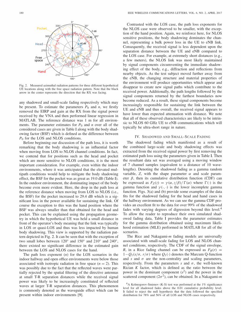
Fig. 2 shows the measured azimuthal radiation patterns for the three usage scenarios plotted relative to the maximum gain observed in free space. It is clear that the antenna radiation patterns were distorted for all three use cases compared to the free space pattern due to the presence of the human body. Interestingly, the forward gain in the pocket was not as significantly affected compared to those for the head and hand. This was most likely due to the antenna orientation and the additional shadowing caused by user’s hand(s). Unlike the pocket location, when the user held the hypothetical UE with his hand(s) (i.e., at head or in front of the body), the device was no longer vertically aligned and thus mismatched with the orientation of the hypothetical eNB. The impact of this can be observed in Fig. 2, where the maximum gain of the radiation pattern for the pocket use case is greater than for the head and hand.3 Another interesting observation is the shadowing which occurs due to the presence of the user’s head. Here, the radiation pattern between 30◦ and 150◦ was more significantly distorted compared to the angles between 210◦ and 330◦ .
The path loss, P, is a measure of the signal attenuation between the TX and RX as a function of the separation distance. It is commonly modeled using the classical power law in logarithmic form as follows
P[dB] = P0 + 10n log10(d/d0) + γ [dB] + χ [dB] (1) _
Path Loss Shadowing Fading
where P0 represents the path loss at the reference distance (d0), n is the path loss exponent which indicates the rate at which the path loss increases with distance and d is the transmitter-receiver (T-R) separation distance. In (1), γ and χ represent
3Although the effects of alignment mismatch on the link performance are addressed in this letter, the polarization effects presented in [7] and [8] may also act on it.
180 IEEE WIRELESS COMMUNICATIONS LETTERS, VOL. 6, NO. 2, APRIL 2017
Fig. 2. Measured azimuthal radiation patterns for three different hypothetical UE locations along with the free space radiation pattern. Note that the black arrow in the center represents the direction that the RX was facing.
any shadowed and small-scale fading respectively which may be present. To estimate the parameters P0 and n, we firstly removed the EIRP and gain at the RX from the signal power received by the VNA and then performed linear regression in MATLAB. The reference distance was 1 m for all environments. The parameter estimates for P0 and n over all of the considered cases are given in Table I along with the body shadowing factor (BSF) which is defined as the difference between P0 for the LOS and NLOS conditions.
Before beginning our discussion of the path loss, it is worth remarking that the body shadowing is an influential factor when moving from LOS to NLOS channel conditions. In fact, we contend that for positions such as the head and pocket which are more sensitive to NLOS conditions, it is the most important consideration. For example, even within the indoor environments, where it was anticipated that the elevated multipath conditions would help to mitigate the body shadowing effect, the BSF for the pocket was as great as 19.0 dB (Table I). In the outdoor environment, the dominating impact of the body become even more evident. Here, the drop in the path loss at the reference distance when moving from LOS to NLOS (i.e., the BSF) for the pocket increased to 29.4 dB which is a significant loss in the power available for sustaining the link. Of course the exception to this was the hand position where the BSF was always smaller than that obtained for the head and pocket. This can be explained using the propagation geometry in which the hypothetical UE was held a small distance in front of the operator’s body meaning that the link was typically in LOS or quasi-LOS and thus was less impacted by human body shadowing. This view is supported by the radiation pattern depicted in Fig. 2. It can be seen that with the exception of two small lobes between 120◦ and 150◦ and 210◦ and 240◦ , there existed no significant difference in the estimated gain between the LOS and NLOS cases for the hand.
The path loss exponent (n) for the LOS scenarios in the indoor hallway and open office environments were below those associated with isotropic radiation in free space (n = 2). This was possibly due to the fact that the reflected waves were partially rejected by the spatial filtering of the directive antennas at small T-R separation distances while the received signal power was likely to be increasingly constituted of reflected waves at larger T-R separation distances. This phenomenon is commonly denoted as the waveguide effect which can be present within indoor environments [9].
Contrasted with the LOS case, the path loss exponents for the NLOS case were observed to be smaller, with the exception of the hand position. Again, we reinforce here, for NLOS sensitive positions, the body shadowing dominates the channel, representing a bulk power loss in the UE to eNB link. Consequently, the received signal is less dependent upon the separation distance between the UE and eNB compared to the LOS case. For example, at extremely short distances (e.g., a few meters), the NLOS link was most likely maintained by signal components circumventing the immediate shadowing effect of the body, e.g., diffraction and reflections from nearby objects. As the test subject moved further away from the eNB, the changing structure and material properties of the environment will produce opportunities which appear and disappear to create new signal paths which contribute to the received power. Additionally, the path lengths followed by the signal components returned by the farthest boundaries now become reduced. As a result, these signal components become increasingly responsible for sustaining the link between the UE and eNB and thus overall, the received signal appears to have lower than expected attenuation with distance. We note that all of these observed characteristics are likely to be intrinsic to NLOS 60 GHz UE to eNB communications which will typically be ultra-short range in nature.
IV. SHADOWED AND SMALL-SCALE FADING
The shadowed fading which manifested as a result of the combined large-scale and body shadowing effects was extracted from the received signal power by first removing the estimated path loss using the parameters given in Table I. Then the resultant data set was averaged using a moving window of 7 channel samples (equivalent to a distance of 10 wavelengths). Denoting the shadowed fading as a gamma random variable, Z, with the shape parameter α and scale parameter β, then its cumulative distribution function (CDF) can be expressed as FZ(z) = γ (α, z/β)/ f(α) where f(·) is the gamma function and γ (·, ·) is the lower incomplete gamma function. Figs. 3(a) and (b) provide some examples of the data fits for the shadowed fading for the head and hand cases in the hallway environment. As we can see the gamma CDF provides an excellent fit to the data for over 99% of the shadowed fades with varying degrees of digression beyond this level.4
To allow the reader to reproduce their own simulated shadowed fading data, Table I provides the parameter estimates for the gamma distribution obtained using maximum likelihood estimation (MLE) performed in MATLAB for all of the scenarios.
The Rice and Nakagami-m fading models are universally associated with small-scale fading for LOS and NLOS channel conditions, respectively. The CDF of the signal envelope, R, in a Rice fading channel can be expressed as FR(r) = 1−Q1(s/σ, r/σ) where Q1(·) denotes the Marcum Q-function and s and σ are the non-centrality and scaling parameters, respectively. From the parameters s and σ , the well-known Rician K factor, which is defined as the ratio between the power in the dominant component (s2) and the power in the scattered component (2σ 2), can be obtained. In a Nakagami-m
4A Kolmogorov-Smirnov (K-S) test was performed at the 1% significance level for all shadowed fades above the 0.01 cumulative probability level. It failed to reject the null hypothesis that the data followed the specified distribution for 78% and 56% of all LOS and NLOS cases respectively.

181 YOO et al.: MEASUREMENTS OF 60 GHZ UE TO ENB CHANNEL FOR SMALL CELL DEPLOYMENTS
TABLE I DIFFERENCE BETWEEN LOWEST RECORDED SIGNAL POWER AND NOISE THRESHOLD (DSN ), PATH LOSS PARAMETERS
AND BODY SHADOWING FACTORS (BSF) ALONG WITH THE PARAMETERS ESTIMATES FOR THE GAMMA, RICE AND NAKAGAMI-m DISTRIBUTIONS FOR THE LOS AND NLOS SCENARIOS
Fig. 3. Empirical CDFs of the shadowed fading observed in the hallway environment for the (a) head and (b) hand positions; empirical CDFs of the small-scale fading observed in the (c) hallway and (d) car park environments for the pocket position.
fading channel, the CDF of the signal envelope, R, can be expressed as FR(r) = γ (m, mr2/Q)/f(m) where m is the fading severity parameter and Q is the mean signal power. Prior to studying the small-scale fading, the path loss and shadowed fading were removed from the measurement data as detailed above. In a similar fashion to the shadowed fading analysis, parameter estimates for the Rice and Nakagami-m fading models were obtained using MLE performed in MATLAB and are provided in Table I.5
As anticipated, there existed a strong dominant signal component (K > 1) for all of the LOS scenarios. The hand position consistently provided the lowest K values across all of the environments. Interestingly, while this use case reported a comparable dominant signal amplitude (s) to the other use cases, its orientation appeared to make it more susceptible to scattered multipath contributions (2σ 2). For the NLOS scenarios, the m parameter was always found to be greater than 2. This result suggests that clustered multipath contributions may have been responsible for shaping the small-scale fading contribution. As an example of the model fits for the small-scale
5It is worth highlighting that the Rice distribution can be used to approx2(K+1)imate the Nakagami-m distribution using the relationship m = 2K+1 [6].
Therefore the LOS results presented here can be appropriately re-parametrized to their Nakagami-m approximations.
fading, Figs. 3(c) and (d) present the empirical CDFs alongside the Rice and Nakagami-m CDFs while the operator carried the hypothetical UE in his pocket in the hallway and car park environments respectively. Both the Rice and Nakagami-m models provided a good fit to the measurement data showing that they can be used to generate small-scale fading data in mm-wave small cell simulations.6
V. CONCLUSION
The characteristics of mm-wave small cell UE to eNB communications channels have been studied under realistic operating conditions. It has been found that how the device is held or positioned relative to the operator’s body will have a discernible effect on the link performance. This is especially prevalent in terms of pattern distortion and the shadowing induced by the human body. To allow our results to be readily reproduced, we have characterized our measured data using traditional path loss, shadowed and small-scale fading models.
REFERENCES
[1] R. C. Daniels and R. W. Heath, Jr., “60 GHz wireless communications: Emerging requirements and design recommendations,” IEEE Veh. Technol. Mag., vol. 2, no. 3, pp. 41–50, Sep. 2007.
[2] S. Rangan, T. S. Rappaport, and E. Erkip, “Millimeter-wave cellular wireless networks: Potentials and challenges,” Proc. IEEE, vol. 102, no. 3, pp. 366–385, Mar. 2014.
[3] J. S. Lu, P. Cabrol, D. Steinbach, and R. V. Pragada, “Measurement and characterization of various outdoor 60 GHz diffracted and scattered paths,” in Proc. MILCOM, San Diego, CA, USA, Nov. 2013, pp. 1238–1243.
[4] N. Moraitis and P. Constantinou, “Indoor channel measurements and characterization at 60 GHz for wireless local area network applications,” IEEE Trans. Antennas Propag., vol. 52, no. 12, pp. 3180–3189, Dec. 2004.
[5] S. Collonge, G. Zaharia, and G. E. Zein, “Influence of the human activity on wide-band characteristics of the 60 GHz indoor radio channel,” IEEE Trans. Wireless Commun., vol. 3, no. 6, pp. 2396–2406, Nov. 2004.
[6] S. L. Cotton and W. G. Scanlon, “A statistical analysis of indoor multipath fading for a narrowband wireless body area network,” in Proc. PIMRC, Helsinki, Finland, Sep. 2006, pp. 1–5.
[7] T. Manabe, Y. Miura, and T. Ihara, “Effects of antenna directivity and polarization on indoor multipath propagation characteristics at 60 GHz,” IEEE J. Sel. Areas Commun., vol. 14, no. 3, pp. 441–448, Apr. 1996.
[8] D. Dupleich et al., “Directional characterization of the 60 GHz indoor-office channel,” in Proc. URSI GASS, Beijing, China, Aug. 2014, pp. 1–4.
[9] A. A. M. Saleh and R. A. Valenzuela, “A statistical model for indoor multipath propagation,” IEEE J. Sel. Areas Commun., vol. 5, no. 2, pp. 128–137, Feb. 1987.
6The K-S test performed at the 1% significance level for all small-scale fades above the 0.01 cumulative probability level failed to reject the null hypothesis for 78% and 78% of all LOS and NLOS cases respectively.