measurements of air concentration and velocities in …
TRANSCRIPT

Freddy Florez Reinhard Prenner Norbert Krouzecky
ISSN 1333-1124 eISSN 1849-1391
MEASUREMENTS OF AIR CONCENTRATION AND VELOCITIES IN A FREE FALLING WATER JET
Summary
The prediction of air entrainment in a free falling water jet (two-phase flow) is affected by large uncertainties. A current research project at the Vienna University of Technology is dealing with this phenomenon by means of experimental tests and CFD-calculations. The experimental investigation was conducted in order to measure the air concentration in such a free falling jet using a fibre-optic probe. The velocity was measured with a high speed camera. The tests were performed on a jet which exits a circular pipe with a diameter of 40 mm. The air concentration was measured transversally at several distances away from the nozzle exit. The test results should provide a data basis for CFD-calculations of the air entrainment in a further research step.
Key words: air entrainment, free falling water jet, air concentration, fibre-optic probe
1. Hydraulic basics and aim of investigation
Air entrainment in a turbulent water jets occurs very often during the operation of hydraulic structures, e.g. at free overfall spillway structures of an arch dam etc.
Fig. 1 Overfall spillways: Tsankov Kamak (BG) and Karun 5 (Iran)
TRANSACTIONS OF FAMENA XL-1 (2016) 57

F. Florez, R. Prenner, Measurements of Air Concentration and Velocities N. Krouzecky in a Free Falling Water Jet
In hydraulic engineering a faster flow of a water body induces an interaction with the surrounding air by means of air bubbles that are entrained in the boundary layer. For lower velocities, the bubbles are usually transported in the vicinity of the surface boundary layer without further mixing. The major entrainment mechanisms of a high speed water flow are the overturning surface waves and the water droplets being projected above the water surface and the water falling down [6].
According to Falvey in [6], under certain circumstances the air inception may be beneficial, e.g., suppression or damping of cavitation phenomena, etc. Vischer and Hager noted in [13] that in the case of aerated turbulent jets the thickness, the initial turbulence and the falling height play an outstanding role during the dispersion (atomization) of a free falling jet. Kobus [8] mentioned that the air entrainment can strongly influence the performance of a hydraulic structure due to changes in the bulk properties of the fluid, changes in the structure of the turbulence, etc.
A free falling water jet disintegrates when it exits a nozzle or an orifice into a surrounding medium (i.e. air) which is substantially less dense than the jet itself. The momentum of the jet is directed mainly downwards. When the jet leaves a nozzle its constitution is as an unbroken column with the presence of ruffled (rippled) forms on the surface. Later on, due to turbulence effects over the surface tension it turns into an unstable flow formed by a degradation into discrete fluids masses - these could be connected or not – finally these will disintegrate into small drops [7].
Fig. 2 Definition sketch of free falling water jets discharging into air [5]
According to Ervine et al. [5], a vertical plunging jet is characterized mainly by three zones as shown schematically in Fig. 2: 1) zone A: the water has a glassy smooth surface, where small waves start to appear due to the influence of the internal turbulence in the liquid; 2) zone B: this is a turbulent and chaotic zone which starts with the breakdown of the circumferential vortices and ends in the breakup of the jet. The air entrains in a boundary layer surrounding the jet passing over the protuberance of the jet. 3) zone C: there is a massive formation of discrete water droplets or satellite droplets which will tend to break up. At this stage, the turbulence fluctuations have penetrated the core of the jet and the flow is no longer a continuous mass of fluid.
58 TRANSACTIONS OF FAMENA XL-1 (2016)

Measurements of Air Concentration and Velocities F. Florez, R. Prenner, in a Free Falling Water Jet N. Krouzecky
Hydraulic engineers are frequently faced with the estimation of the air entrainment in a turbulent water jet and its consequence during operation on the design of a hydraulic structure, e.g. at spillways of a dam etc. The determination of the air entrainment in a free falling water jet is a particular challenge, because large uncertainties can occur therein. Therefore, a specific research project was set up at the Research Centre of Hydraulic Engineering which deals with the air entrainment in a falling jet. Eventually, the test results should provide data as a basis for CFD-calculations. This paper gives an excerpt from an experimental test series which was carried out in the course of this investigation.
2. Experimental investigations
The experimental tests were carried out in the Hydraulics Laboratory of the Institute of Hydraulic Engineering and Water Resources Management of the Vienna University of Technology. The tests were performed on a circular jet form with different discharges. The measurements of the air entrainment (void fraction) and the fall-velocity of the jet were carried out by a fibre-optic double probe and a high speed camera.
2.1 Model setup The rig facility consisted of a 5m high steel trestle which was built to measure the air
entrainment and air transport of free falling jets. The pump system of the laboratory fed the water tank by means of a steel pipe (DN150). The flow discharged into the reservoir was regulated manually by a valve and recorded by a magneto-inductive flow meter (IDM).
Two configurations were set up at the top of the steel trestle in order to generate vertical discharges into the quiescent air: a) the nozzles attached to the bottom of a water tank, in which the water velocity was determined by using high speed photography (see Fig. 3) and b) the nozzles directly attached to the pump line of the laboratory in which measurements of the air concentration were done. The advantage of using both configurations allowed distinguishing the influence of the inlet conditions on the flow. Table 1 Experimental programme to determine the water jet velocity for nozzle diameter d = 40 mm.
Qw (l/s) Uo (m/s) Code MP Re (105) We (103) Oh (104) Fr 2.56 2.04 V-M1-1 298 0.813 2.30 5.9 3.3 2.82 2.24 V-M1-2 428 0.896 2.78 5.9 3.6 3.09 2.46 V-M1-3 409 0.982 3.35 5.9 3.9 3.35 2.67 V-M1-4 496 1.06 3.95 5.9 4.3 3.62 2.88 V-M1-5 429 1.15 4.59 5.9 4.6 4.00 3.18 V-M1-6 415 1.27 5.60 5.9 5.1
In Tables 1 and 2, the experimental programme is presented, where d is the diameter of the nozzle, Qw is the water discharge, U0 is the outlet velocity, Code is an identifier of the experiment, MP is the number of measurement points for the velocity, Re is the Reynolds number, We is the Weber number, Oh is the Ohnesorge number and Fr is the Froude number. Table 2 Experimental programme to measure the air concentration C (%) of the water jet (nozzle d = 40 mm).
Qw (l/s) Uo (m/s) Code Re (105) We (103) Oh (104) Fr 2.56 2.04 A-M1-1 0.813 2.30 5.9 3.3 2.82 2.24 A-M1-2 0.896 2.78 5.9 3.6 3.09 2.46 A-M1-3 0.982 3.35 5.9 3.9 3.35 2.67 A-M1-4 1.06 3.95 5.9 4.3 3.62 2.88 A-M1-5 1.15 4.59 5.9 4.6 5.00 3.98 A-M1-6 1.59 8.70 5.9 6.4
TRANSACTIONS OF FAMENA XL-1 (2016) 59

F. Florez, R. Prenner, Measurements of Air Concentration and Velocities N. Krouzecky in a Free Falling Water Jet
Fig. 3 Sketch of the physical model configuration a): model in operation, model rig with high speed camera
guide wall flow straightener nozzle
water tank
water supply pipe
high speed camera
jet casing box
d = 40 mm
shelf structure
Qw = 5 l/s
Qw = 2.8 l/s light
light
light
60 TRANSACTIONS OF FAMENA XL-1 (2016)

Measurements of Air Concentration and Velocities F. Florez, R. Prenner, in a Free Falling Water Jet N. Krouzecky
2.2 Techniques for the measurement of air concentration Fibre-optic double probes have been widely used in the chemical and nuclear industries
to measure air concentration and bubble properties (Cartellier [4]). Serdula and Loewen [12] demonstrated that fibre-optic probes can be used to make reasonably accurate measurements of the void fraction even in the dispersed regime where the void fraction is extremely small. Likewise, the use of optic probes has been broadened in the field of hydraulic engineering for measuring air concentration and velocity of the mixture on stepped spillways and chutes at high velocities as it has been reported by Boes and Hager [1], Boes [2], Boes [3], Kramer [9] and Pfister [10]. After having carried out some pretests, Boes [3] stated that the system measures void fraction and flow velocity with an error smaller than ±5%.
A sapphire fibre-optic double probe manufactured by RBI-Instrumentation® in 2013 was used to measure the local air concentration C (%) at several lengths from the nozzle exit. Unlike the studies and the wide validations developed by Boes and Hager [1], Boes [2], Boes [3], Kramer [9] and Pfister [10] in chutes and step spillways, the current generation of sapphire-based optic fibre has improved performance by mitigating the light transmission losses when they are used in harsh environments (extremes of temperature and pressure) or high dynamics of the flow.
The two-phase flow device comprises the following elements [11]: a probe with a double sapphire tip, an optoelectronic amplification module, a data acquisition board, a PC and the software ISO-Lite provided by the manufacturer. The use of the dual-tips probes allows not only measurement of the air concentration and the bubble-count rate but with the second tip it is possible to estimate additionally the size distribution (chord length), the velocity of the air-water mixture and the specific interface area.
The measuring principle is based on the different refraction indices of air (dry air 0%) and water (clear water 100%). Initially, the optoelectronic module transmits light via fibre optics to an optic prism-shaped sapphire probe tip through which the ray of emitted light is either partially reflected or diffracted. This is explained in Fig. 4, where a sapphire fibre-optic double probe is immersed in an air-water mixture which moves in the flow direction. The first tip of the probe is surrounded by a single bubble of air (the ray of light is reflected) and the second one is in the water (the ray of light is diffracted). Subsequently, the optical signal in terms of the quantity of the reflected light is converted into an electrical signal by a photo-sensitive element located in the optoelectronic unit [11].
Fig. 4 Fibre-optic double probe operating principle [11]
When a bubble travels through the optic probe, a variable level analogue signal is produced by the optic probe and consequently the raw signal captured is shaped (as shown in Fig. 5) by the optoelectronic unit into a transistor-transistor logic (TTL) signal by an automatic threshold method operation. The principle consists of the recognition of the
TRANSACTIONS OF FAMENA XL-1 (2016) 61

F. Florez, R. Prenner, Measurements of Air Concentration and Velocities N. Krouzecky in a Free Falling Water Jet
coincidence of the probe signals. With an actual tip distance, the local velocity of air bubbles can be calculated with the time shift between the occurrences of a pair of events corresponding to the same bubble passing across both probe tips.
Fig. 5 Signal shaping [11]
As can be seen in Fig. 6, the sapphire optic double probe must be positioned perpendicularly to the vertical flow direction to guarantee that the two tips are co-aligned.
Fig. 6 Scheme of fibre-optic probe measurement (adapted from [11])
The optoelectronic amplifier (unit) emits the light signal E through the optical fibre; once it arrives at the sensitive cone-shaped tip it is reflected as signal R and then this signal can be processed by a photo-sensitive element which converts the optical signal into an electrical signal. Consequently, the signal is shaped (squared signal), then it is acquired by an interface board and finally transferred to a personal computer (PC) where the data can be analysed and processed by means of the software ISO Lite provided by RBI [11].
Among the parameters that can be obtained from the data processing are the following: Over a single tip the acquisition time, number of bubbles, average phase time and
phase-time histograms can be visualized. The void fraction or air concentration C (%) is calculated according to equation (1).
tt
C ggi (%) , (1)
where the time averaged local void fraction or air concentration C (%) is defined as the duration in the time of the air fraction tg over the total time of measure t at a certain point (x,y,z).
62 TRANSACTIONS OF FAMENA XL-1 (2016)

Measurements of Air Concentration and Velocities F. Florez, R. Prenner, in a Free Falling Water Jet N. Krouzecky
Only the first tip is able to determine the void fraction of the fluid because it might cause disruption of the flow at the second tip and this might affect the results. The measuring time in the tests was 200 s, the minimum acquisition time to obtain reliable results for the void fraction was about 150 s. The methodology consisted of building a converge curve based on the grouping of successive data n of air concentration into intervals in order to evaluate the variation of the air concentration on the width of the time interval. In Fig. 7, the temporal convergence of the air concentration for a single test built with different number of points (n = 16 and 55) and a tolerance of 0.3% is presented.
Fig. 7 Temporal convergence of air concentration. Averaged air concentration C (%) = 81.16
The advantages of using a sapphire fibre-optic probe are: The response time is faster in contrast to electrical probes. The response time of a
sapphire fibre-optic probe is in the order of 1μs to 6μs instead of 10μs when electrical probes are used [1].
As an intrusive device for void fraction detection in air-water mixtures, the tiny head size ( 0.5mm) of the optic probe plays an appropriate role during the measurements.
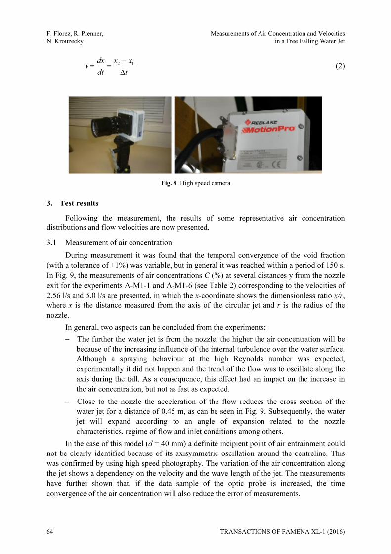
2.3 Measurement of flow velocities To validate the jet flow velocities, a high speed camera MotionPro (set to a frame rate
of 250 fps, resolution of 1024x768 pxs and a shutter speed of 1/4000 s) was used at different elevations (Fig. 8). The records allowed also an analysis of the jet flow, e.g. break-up point, air-entrainment process etc.
The use of an image processing technique allows the determination of the velocity of the water jet along its falling path related to a series of images. Each image captured by a high speed camera is distorted and not uniformly scaled because of the effect of the lens, positioning of the camera and camera angle, among others. Moreover, in order to get an undistorted image it was necessary to perform corrections each time by using the model 2D-projective geometric transformation using Matlab 8.3. Once the series of frames were recorded, the analysis followed which included identifying a visible wave or protuberance in the water surface, its position x1 in the frame n was referenced and then the next position x2 of the same particle in the immediate consecutive frame n+1 was captured. As the frame rate of the high speed camera is established at the beginning of a shoot sequence, the time between frames t can be determined and finally the instantaneous flow velocity v can be estimated as:
TRANSACTIONS OF FAMENA XL-1 (2016) 63
F. Florez, R. Prenner, Measurements of Air Concentration and Velocities N. Krouzecky in a Free Falling Water Jet
txx
dtdxv
12 (2)
Fig. 8 High speed camera
3. Test results
Following the measurement, the results of some representative air concentration distributions and flow velocities are now presented.
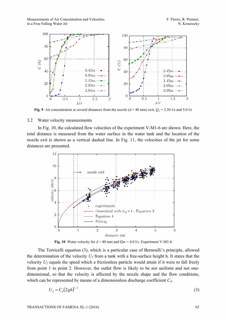
3.1 Measurement of air concentration During measurement it was found that the temporal convergence of the void fraction
(with a tolerance of ±1%) was variable, but in general it was reached within a period of 150 s. In Fig. 9, the measurements of air concentrations C (%) at several distances y from the nozzle exit for the experiments A-M1-1 and A-M1-6 (see Table 2) corresponding to the velocities of 2.56 l/s and 5.0 l/s are presented, in which the x-coordinate shows the dimensionless ratio x/r, where x is the distance measured from the axis of the circular jet and r is the radius of the nozzle.
In general, two aspects can be concluded from the experiments: The further the water jet is from the nozzle, the higher the air concentration will be
because of the increasing influence of the internal turbulence over the water surface. Although a spraying behaviour at the high Reynolds number was expected, experimentally it did not happen and the trend of the flow was to oscillate along the axis during the fall. As a consequence, this effect had an impact on the increase in the air concentration, but not as fast as expected.
Close to the nozzle the acceleration of the flow reduces the cross section of the water jet for a distance of 0.45 m, as can be seen in Fig. 9. Subsequently, the water jet will expand according to an angle of expansion related to the nozzle characteristics, regime of flow and inlet conditions among others.
In the case of this model (d = 40 mm) a definite incipient point of air entrainment could not be clearly identified because of its axisymmetric oscillation around the centreline. This was confirmed by using high speed photography. The variation of the air concentration along the jet shows a dependency on the velocity and the wave length of the jet. The measurements have further shown that, if the data sample of the optic probe is increased, the time convergence of the air concentration will also reduce the error of measurements.
64 TRANSACTIONS OF FAMENA XL-1 (2016)
Measurements of Air Concentration and Velocities F. Florez, R. Prenner, in a Free Falling Water Jet N. Krouzecky
Fig. 9 Air concentration at several distances from the nozzle (d = 40 mm) exit, Qw = 2.56 l/s and 5.0 l/s
3.2 Water velocity measurements In Fig. 10, the calculated flow velocities of the experiment V-M1-6 are shown. Here, the
total distance is measured from the water surface in the water tank and the location of the nozzle exit is shown as a vertical dashed line. In Fig. 11, the velocities of the jet for some distances are presented.
Fig. 10 Water velocity for d = 40 mm and Qw = 4.0 l/s. Experiment V-M1-6
The Torricelli equation (3), which is a particular case of Bernoulli’s principle, allowed the determination of the velocity U2 from a tank with a free-surface height h. It states that the velocity U2 equals the speed which a frictionless particle would attain if it were to fall freely from point 1 to point 2. However, the outlet flow is likely to be not uniform and not one-dimensional, so that the velocity is affected by the nozzle shape and the flow conditions, which can be represented by means of a dimensionless discharge coefficient Cd.
2/12 2ghCU d (3)
TRANSACTIONS OF FAMENA XL-1 (2016) 65

F. Florez, R. Prenner, Measurements of Air Concentration and Velocities N. Krouzecky in a Free Falling Water Jet
Fig. 11 Water jet configuration at several distances for d = 40 mm
The equation of uniform acceleration in the case of bodies moving under the influence of gravity g is presented in equation (4).
ghUU 220
2 (4)
where U is the final velocity, U0 is the initial velocity, g the standard gravity and h is the displacement.
In Fig. 12, the fitted third-order polynomial equations of the experimental results of the experiments (Table 1) are shown. In order to represent the physics of the experiments, the fit was constrained at the inlet boundary condition in (h,v)→(0,U0) by using a linear equality constraints method which solves the linear least-squares problem with a linear constraint in order to agree with the exit velocity obtained experimentally.
For all the experiments the behaviour of the jet had a sinuous regime with the presence of a potential core as in regions A and B in Fig. 2. In general, the disintegration of the cylindrical jet will take place by means of axisymmetric surface oscillations and spiral formations as was found experimentally. The analysis of the surface jet velocities showed no breakup along the whole jet due to the restricted height of the model. Hence, the velocity distribution across the circular jet could not be determined, but in general the flow velocity could be calculated according to equation (4).
It is worth mentioning that the implementation of the computer-aided vision, specifically the video tracking techniques (unsupervised technique) could not be successfully applied in the current research due to the difficulties of tracking a particle of fluid during falling. The challenge was to handle the sudden changes in the light, the reflection of waves on the water surface and even several emitted sources of lights with a certain frequency were affecting the quality of the image.
66 TRANSACTIONS OF FAMENA XL-1 (2016)

Measurements of Air Concentration and Velocities F. Florez, R. Prenner, in a Free Falling Water Jet N. Krouzecky
Fig. 12 Water velocity of jets discharging into quiescent air.
4. Conclusions
The determination of the air concentration in a high speed water jet is a particular challenge in hydraulic engineering. The optic probe is often successfully used for measurements in two-phase flows tasks in the research work of hydraulic modelling where a high accuracy is required. The advantages of the used equipment are: 1) a very fast acquisition rate (sampling frequency of 106 Hz) in contrast to other probes, e.g. conductivity probes etc., which have lower resolutions; 2) due to the tiny probe sapphire tip diameter of 80 µm, a reduced intrusiveness of the devices into the flow is given, which results also in the capability of capturing and detecting tiny bubbles; 3) its applicability in harsh environments, at high pressures (<0.5 MPa) and temperatures (<80oC) and, 4) when a double probe is used, parallel to the main flow direction, the bubble velocity (water velocity) and bubble diameter can be determined.
The main disadvantage is the lack of supplementary flow information like velocity fluctuations and turbulence information; other disadvantages are the small residual probe intrusiveness, the one dimensionality of flow information and the highly fragile probe tips. High speed photography could be used complementary to study the flow phenomena.
Beside the use of the described technique in the hydraulic modelling of hydraulic structures it can be also used in environmental engineering in cases when the air entrainment in waste water treatment is important. There is also a wide range of special applications of this two-phase flow measurement technique in mechanical and chemical engineering where mixing processes are of interest.
REFERENCES [1] R. Boes and W. Hager: Fiber optical experimentation in two-phase cascade flow. Proc. Intl. RCC Dams
Seminar, 1998. [2] R. Boes: Fiberoptische Messung von lokalen Luftkonzentrationen und Fliegeschwindigkeiten in
Zweiphasenströmungen. Wasserbauliche Mitteilungen Heft 13, pp. 205–214, Institut für Wasserbau und Technische Hydromechanik der TU Dresden, 1998
[3] R. Boes: Zweiphasenströmung und Energieumsetzung an Grosskaskaden. PhD thesis, Eidgenössischen Technischen Hochschule Zürich, 2000.
TRANSACTIONS OF FAMENA XL-1 (2016) 67

F. Florez, R. Prenner, Measurements of Air Concentration and Velocities N. Krouzecky in a Free Falling Water Jet
[4] A. Cartelier: Optical probes for local void fraction measurements: characterization of performance. Rev. Sci. Instrum., vol. 61, no. 2, pp. 874-886, Feb. 1990.
[5] D. Ervine, H. Falvey, and W. Withers: Pressure fluctuations on plunge pool floors. Journal of hydraulic research, vol. 35, pp. 257–279, 1996.
[6] H. Falvey: Air-water flow in hydraulic structures - Engineering monograph No. 41. United State Department of the Interior - Water and Power Resources Services 1980.
[7] F. Florez: Air entrainment in free falling water jets. PhD thesis (in preparation), Institute of Hydraulic Engineering and Water Resources Management -Vienna University of Technology, 2015.
[8] H. Kobus: An introduction to air-water flows in hydraulics. Institut für Wasserbau der Universität Stuttgart, Okt., 1985
[9] K. Kramer: Development of aerated chute flow. VAW Mitteilung 183, ETH Zürich, 2004. [10] M. Pfister: Schussrinnenbelüfter - Lufttransport ausgelöst durch interne Abflussstruktur. VAW
Mitteilung 203, ETH Zürich, 2008. [11] RBI Instrumentation et Mesure: User’s Guide, Two-Phase Flow equipment with ATL unit. Chemin du
Vieux Chene -F-38240 Meylan, France, 2013. [12] C. D. Serdula and M. R. Loewen: Experiments investigating the use of fiber-optic probes for measuring
bubble-size distributions. IEEE Journal of Oceanic Engineering, vol. 23, no. 4, pp. 385-399, Oct. 1998. [13] D. L. Vischer and W.H. Hager: Energy dissipators. Hydraulic Structures Design Manual. International
Association for Hydraulic Research, A.A. Balkelma, Rotterdam 1995.
Submitted: 08.4.2015 Accepted: 28.01.2016
Freddy Florez Reinhard Prenner Norbert Krouzecky Institute of Hydraulic Engineering and Water Resources Management Vienna University of Technology Karlsplatz 13 E222/A-1040 Wien Austria
68 TRANSACTIONS OF FAMENA XL-1 (2016)