measurement of water flow in fully charged closed conduits...
TRANSCRIPT

Reference numberISO 4064-3:2005(E)
© ISO 2005
INTERNATIONAL STANDARD
ISO4064-3
Third edition2005-10-15
Measurement of water flow in fully charged closed conduits — Meters for cold potable water and hot water — Part 3: Test methods and equipment
Mesurage de débit d'eau dans les conduites fermées en pleine charge — Compteurs d'eau potable froide et d'eau chaude —
Partie 3: Méthodes et matériels d'essai
Copyright International Organization for Standardization Reproduced by IHS under license with ISO
Not for ResaleNo reproduction or networking permitted without license from IHS
--`,,```,,,,````-`-`,,`,,`,`,,`---

ISO 4064-3:2005(E)
PDF disclaimer This PDF file may contain embedded typefaces. In accordance with Adobe's licensing policy, this file may be printed or viewed but shall not be edited unless the typefaces which are embedded are licensed to and installed on the computer performing the editing. In downloading this file, parties accept therein the responsibility of not infringing Adobe's licensing policy. The ISO Central Secretariat accepts no liability in this area.
Adobe is a trademark of Adobe Systems Incorporated.
Details of the software products used to create this PDF file can be found in the General Info relative to the file; the PDF-creation parameters were optimized for printing. Every care has been taken to ensure that the file is suitable for use by ISO member bodies. In the unlikely event that a problem relating to it is found, please inform the Central Secretariat at the address given below.
© ISO 2005 All rights reserved. Unless otherwise specified, no part of this publication may be reproduced or utilized in any form or by any means, electronic or mechanical, including photocopying and microfilm, without permission in writing from either ISO at the address below or ISO's member body in the country of the requester.
ISO copyright office Case postale 56 • CH-1211 Geneva 20 Tel. + 41 22 749 01 11 Fax + 41 22 749 09 47 E-mail [email protected] Web www.iso.org
Published in Switzerland
ii © ISO 2005 – All rights reserved
Copyright International Organization for Standardization Reproduced by IHS under license with ISO
Not for ResaleNo reproduction or networking permitted without license from IHS
--`,,```,,,,````-`-`,,`,,`,`,,`---

ISO 4064-3:2005(E)
© ISO 2005 – All rights reserved iii
Contents Page
Foreword............................................................................................................................................................. v 1 Scope ..................................................................................................................................................... 1 2 Normative references ........................................................................................................................... 1 3 Terms and definitions........................................................................................................................... 3 4 Requirements common to all tests ..................................................................................................... 3 4.1 Preliminary requirements .................................................................................................................... 3 4.2 Water quality ......................................................................................................................................... 3 4.3 Other reference conditions.................................................................................................................. 4 4.4 Location ................................................................................................................................................. 4 5 Tests to determine errors of indication .............................................................................................. 4 5.1 General................................................................................................................................................... 4 5.2 Principle................................................................................................................................................. 4 5.3 Description of the test bench .............................................................................................................. 4 5.4 Pipework ................................................................................................................................................ 5 5.5 Calibrated reference device................................................................................................................. 8 5.6 Meter reading ........................................................................................................................................ 8 5.7 Major factors affecting the determination of errors of indication ................................................... 9 5.8 Intrinsic errors (of indication) .............................................................................................................. 10 5.9 Water temperature tests..................................................................................................................... 11 5.10 Internal pressure tests ....................................................................................................................... 11 5.11 Flow reversal tests.............................................................................................................................. 11 5.12 Irregularity in velocity fields tests..................................................................................................... 12 5.13 Interpretation of results...................................................................................................................... 14 6 Static pressure tests........................................................................................................................... 14 6.1 Object of tests ..................................................................................................................................... 14 6.2 Preparation .......................................................................................................................................... 14 6.3 Test procedure – In-line meters ........................................................................................................ 14 6.4 Test procedure – Concentric meters ................................................................................................ 14 6.5 Acceptance criteria............................................................................................................................. 15 7 Pressure-loss test............................................................................................................................... 15 7.1 Object of test ....................................................................................................................................... 15 7.2 Preparation .......................................................................................................................................... 15 7.3 Test procedure .................................................................................................................................... 16 7.4 Acceptance criteria............................................................................................................................. 17 8 Durability tests .................................................................................................................................... 19 8.1 Continuous flow test .......................................................................................................................... 19 8.2 Discontinuous flow test ..................................................................................................................... 21 9 Performance tests for electronic water meters and mechanical meters fitted with
electronic devices............................................................................................................................... 24 9.1 Introduction ......................................................................................................................................... 24 9.2 General requirements......................................................................................................................... 25 9.3 Climatic and mechanical environment ............................................................................................. 27 9.4 Electromagnetic environment ........................................................................................................... 33 9.5 Power supply....................................................................................................................................... 37 10 Test programme for pattern approval............................................................................................... 43 10.1 General................................................................................................................................................. 43 10.2 Performance tests applicable to all water meters ........................................................................... 44
Copyright International Organization for Standardization Reproduced by IHS under license with ISO
Not for ResaleNo reproduction or networking permitted without license from IHS
--`,,```,,,,````-`-`,,`,,`,`,,`---

ISO 4064-3:2005(E)
iv © ISO 2005 – All rights reserved
10.3 Electronic water meters, mechanical water meters fitted with electronic devices, and their separable parts.................................................................................................................................... 44
10.4 Pattern approval of separable parts of a water meter..................................................................... 44 11 Tests for initial verification ................................................................................................................ 45 11.1 General ................................................................................................................................................. 45 11.2 Static pressure test............................................................................................................................. 45 11.3 Error of indication measurements .................................................................................................... 45 11.4 Water temperature of tests................................................................................................................. 46 12 Test report............................................................................................................................................ 46 12.1 General ................................................................................................................................................. 46 12.2 Pattern approval test report — Required contents.......................................................................... 47 Annex A (normative) Calculating the relative error of indication of a water meter ................................... 50 Annex B (normative) Flow disturbance test equipment............................................................................... 55 Annex C (informative) Manifold — Examples of methods and components used for testing
concentric water meters..................................................................................................................... 69
Copyright International Organization for Standardization Reproduced by IHS under license with ISO
Not for ResaleNo reproduction or networking permitted without license from IHS
--`,,```,,,,````-`-`,,`,,`,`,,`---

ISO 4064-3:2005(E)
© ISO 2005 – All rights reserved v
Foreword
ISO (the International Organization for Standardization) is a worldwide federation of national standards bodies (ISO member bodies). The work of preparing International Standards is normally carried out through ISO technical committees. Each member body interested in a subject for which a technical committee has been established has the right to be represented on that committee. International organizations, governmental and non-governmental, in liaison with ISO, also take part in the work. ISO collaborates closely with the International Electrotechnical Commission (IEC) on all matters of electrotechnical standardization.
International Standards are drafted in accordance with the rules given in the ISO/IEC Directives, Part 2.
The main task of technical committees is to prepare International Standards. Draft International Standards adopted by the technical committees are circulated to the member bodies for voting. Publication as an International Standard requires approval by at least 75 % of the member bodies casting a vote.
Attention is drawn to the possibility that some of the elements of this document may be the subject of patent rights. ISO shall not be held responsible for identifying any or all such patent rights.
ISO 4064-3 was prepared by Technical Committee ISO/TC 30, Measurement of fluid flow in closed conduits, Subcommittee SC 7, Volume methods including water meters.
This third edition cancels and replaces the second edition (ISO 4064-3:1999), which has been technically revised, as well as cancelling and replacing ISO 7858-3:1992.
ISO 4064 consists of the following parts, under the general title Measurement of water flow in fully charged closed conduits — Meters for cold potable water and hot water:
⎯ Part 1: Specifications
⎯ Part 2: Installation requirements
⎯ Part 3: Test methods and equipment
Copyright International Organization for Standardization Reproduced by IHS under license with ISO
Not for ResaleNo reproduction or networking permitted without license from IHS
--`,,```,,,,````-`-`,,`,,`,`,,`---

Copyright International Organization for Standardization Reproduced by IHS under license with ISO
Not for ResaleNo reproduction or networking permitted without license from IHS
--`,,```,,,,````-`-`,,`,,`,`,,`---

INTERNATIONAL STANDARD ISO 4064-3:2005(E)
© ISO 2005 – All rights reserved 1
Measurement of water flow in fully charged closed conduits — Meters for cold potable water and hot water —
Part 3: Test methods and equipment
1 Scope
This part of ISO 4064 specifies the test methods and means to be employed in determining the principal characteristics of water meters.
This part of ISO 4064 is applicable to cold potable water and hot water concentric and combination meters, which can withstand maximum admissible working pressures (MAP) equal to at least 1 MPa (10 bar) 0,6 MPa (6 bar) for meters W DN 500 mm and a maximum admissible temperature for cold potable water meters of 30 °C and for hot water meters of up to 180 °C, depending on the class.
This part of ISO 4064 also applies to water meters based on electrical or electronic principles and to water meters based on mechanical principles incorporating electrical devices, used to meter the actual volume flow of cold potable water and hot potable water.
In the case where water meters have a permanent flowrate of less than 160 m3/h, in order to meet individual test laboratory limitations the test schedule may make provisions for modification of the reference conditions, when testing specifically for endurance or for performance under influence quantities.
NOTE Attention is drawn to the fact that national legislation may apply in the country of use, which will take precedence over the provisions of this part of ISO 4064.
2 Normative references
The following referenced documents are indispensable for the application of this document. For dated references, only the edition cited applies. For undated references, the latest edition of the referenced document (including any amendments) applies.
ISO 228-1, Pipe threads where pressure-tight joints are not made on the threads — Part 1: Dimensions, tolerances and designation
ISO 286-2, ISO system of limits and fits — Part 2: Tables of standard tolerance grades and limit deviations for holes and shafts
ISO 4064-1:2005, Measurement of water flow in fully charged closed conduits — Meters for cold potable water and hot water — Part 1: Specifications
ISO 4064-2, Measurement of water flow in fully charged closed conduits — Meters for cold potable water and hot water — Part 2: Installation requirements
ISO 5168, Measurement of fluid flow — Procedures for the evaluation of uncertainties
ISO 7005-2, Metallic flanges — Part 2: Cast iron flanges
Copyright International Organization for Standardization Reproduced by IHS under license with ISO
Not for ResaleNo reproduction or networking permitted without license from IHS
--`,,```,,,,````-`-`,,`,,`,`,,`---

ISO 4064-3:2005(E)
2 © ISO 2005 – All rights reserved
ISO 7005-3, Metallic flanges — Part 3: Copper alloy and composite flanges
ISO Guide to the expression of uncertainty in measurement (GUM), 1995
IEC 60068-1:1988, Environmental testing — Part 1: General and guidance
IEC 60068-2-1:1974, Environmental testing — Part 2 Tests. Tests A: Cold
IEC 60068-2-2:1993, Environmental testing — Part 2: Tests. Tests B: Dry heat
IEC 60068-2-30:1980, Environmental testing — Part 2 Tests. Test Db and guidance: Damp heat, cyclic (12h + 12h cycle)
IEC 60068-2-31:1993, Environmental testing — Part 2 Tests. Test Ec: Drop and topple, primarily for equipment-type specimens
IEC 60068-2-47:1999, Environmental testing — Part 2-47:Test: — Mounting of components, equipment and other articles for vibration, impact and similar dynamic tests
IEC 60068-2-64:1993, Environmental testing — Part 2: Test methods — Test Fh: Vibration, broad-band random (digital control) and guidance
IEC 60068-3-1:1974, Environmental testing — Part 3: Background information — Section One: Cold and dry heat tests
IEC 60068-3-4:2001, Environmental testing — Part 3-4: Supporting documentation and guidance — Damp heat tests
IEC 61000-4-2:1995, Electromagnetic compatibility (EMC) — Part 4: Testing and measurement techniques — Section 2: Electrostatic discharge immunity test. Basic EMC Publication
IEC 61000-4-3 Electromagnetic compatibility (EMC) — Part 4-3: Testing and measurement techniques — Radiated, radio-frequency, electromagnetic field immunity test
IEC 61000-4-4:1995, Electromagnetic Compatibility (EMC) — Part 4-5: Testing and Measurement Techniques — Surge Immunity Tests
IEC 61000-4-5:1995, Electromagnetic Compatibility (EMC) — Testing and measurement techniques — Part 4-5: Surge immunity test
IEC 61000-4-11:1994, Electromagnetic compatibility (EMC) — Part 4-11: Testing and measurement techniques — Voltage dips, short interruptions and voltage variations immunity tests
ENV 50204:1995, Radiated electromagnetic field from digital radio telephones. Immunity test
OIML D 4:1981, Installation and storage conditions for cold water meters
OIML D 11:1994, General requirements for electronic measuring instruments
OIML G 13:1989, Planning of metrology and testing laboratories (P 7)
Copyright International Organization for Standardization Reproduced by IHS under license with ISO
Not for ResaleNo reproduction or networking permitted without license from IHS
--`,,```,,,,````-`-`,,`,,`,`,,`---

ISO 4064-3:2005(E)
© ISO 2005 – All rights reserved 3
3 Terms and definitions
For the purposes of this document, the terms and definitions given in ISO 4064-1 and the following apply.
3.1 combination meter changeover flowrate with decreasing flow Qx1 flowrate occurring when the pressure drop in the combination meter increases suddenly in parallel with a cessation of flow in the larger meter and a visible increase in flow in the smaller meter
3.2 combination meter changeover flowrate with increasing flow Qx2 flowrate occurring when the pressure drop in the combination meter decreases suddenly in parallel with a start-up of flow in the larger meter and a visible reduction in the flow in the smaller meter.
3.3 relative error ε error, expressed as a percentage, defined by the equation:
i a
a100
V VV
ε−
= ×
where
Vi is the indicated volume;
Va is the actual volume.
NOTE More detail is provided in Annex A. ISO 4064-1 gives the maximum permissible errors.
3.4 test flowrate mean flowrate calculated from the indication of the calibrated reference device and the test duration
4 Requirements common to all tests
4.1 Preliminary requirements
Before starting testing, a written test programme shall be compiled, and shall include, e.g. a description of the tests for the determination of measurement error, pressure loss and wear resistance. The programme may also define the necessary levels of acceptability and stipulate how the test results should be interpreted.
4.2 Water quality
Water meter tests shall use water. The water shall be that of the public potable water supply or shall meet the same requirements. If water is being recycled, measures shall be taken to prevent residual water in the meter from becoming harmful to human beings.
The water shall not contain anything capable of damaging the meter or adversely affecting its operation. It shall not contain air bubbles.
Copyright International Organization for Standardization Reproduced by IHS under license with ISO
Not for ResaleNo reproduction or networking permitted without license from IHS
--`,,```,,,,````-`-`,,`,,`,`,,`---

ISO 4064-3:2005(E)
4 © ISO 2005 – All rights reserved
4.3 Other reference conditions
All other applicable influence quantities, except for the influence quantity being tested, shall be held at the following values during pattern approval tests on a water meter:
Flowrate: 0,7 × (Q2 + Q3) ± 0,03 × (Q2 + Q3)
Ambient temperature range: 15 °C to 25 °C 1)
Ambient relative humidity range: 45 % to 75 % 1)
Ambient atmospheric pressure range: 86 kPa to 106 kPa (0,86 bar to 1,06 bar)
Power supply voltage (mains a.c.): Nominal voltage (Unom) ± 5 %
Power supply frequency: Nominal frequency (fnom) ± 2 %
Power supply voltage (battery): A voltage V in the range; Ubmin u V u Ubmax
Working water temperature: See ISO 4064-1:2005, 5.4.1, Table 5
Working water pressure: 200 kPa (2 bar)
During each test, the temperature and relative humidity shall not vary by more than 5 °C or 10 % respectively within the reference range.
4.4 Location
The environment chosen for the meter tests shall be in accordance with the principles of OIML G 13, and shall be free from unintended disturbing influences, e.g. ambient temperature variation and vibration.
5 Tests to determine errors of indication
5.1 General
The method described in this part of ISO 4064 to determine measurement errors is the so-called “collection” method in which the quantity of water passed through the water meter is collected in one or more collecting vessels and the quantity determined volumetrically or by weighing. Other methods may be used, provided the accuracy levels of testing stated in this part of ISO 4064 be attained.
Checking facilities of electronic devices is included in this section.
5.2 Principle
The checking of the measurement error consists of comparing the indications given by the meter under test against a calibrated reference device.
5.3 Description of the test bench
The test bench typically consists of:
a) a water supply (mains, non-pressurized tank, pressurized tank, pump, etc.);
b) pipework;
1) When the ambient temperature and/or ambient relative humidity exceed the above-mentioned ranges, the effect on the error of indication shall be taken into account.
Copyright International Organization for Standardization Reproduced by IHS under license with ISO
Not for ResaleNo reproduction or networking permitted without license from IHS
--`,,```,,,,````-`-`,,`,,`,`,,`---

ISO 4064-3:2005(E)
© ISO 2005 – All rights reserved 5
c) a calibrated reference device (calibrated tank, reference meter, etc.);
d) means for measuring the time of the test;
e) devices for automating the test;
f) means for measuring water temperature;
g) means for measuring water pressure;
h) means for determining density, if necessary;
i) means for determining conductivity, if necessary.
5.4 Pipework
5.4.1 Description
Pipework shall include:
a) a test section in which the meter(s) is (are) placed;
b) means for establishing the desired flowrate;
c) one or two isolating devices;
d) means for determining the flowrate;
and, if necessary:
e) one or more air bleeds;
f) a non-return device;
g) an air separator;
h) a filter;
i) means for checking that the pipework is filled to a datum level before and after test.
During the test, flow leakage, flow input and flow drainage shall not occur between the meter(s) and the reference device or from the reference device.
The pipework shall be such that at the outlet of all meters a positive pressure exists of at least 0,3 bar at any flowrate.
5.4.2 Test section
The test section includes, in addition to the meter(s):
a) one or more pressure tappings for the measurement of pressure, of which one pressure tapping is situated upstream of, and close to, the (first) meter;
b) if necessary, means for measuring the temperature of the water at the entry to the (first) meter.
None of the pipe components or devices placed in the measuring section shall cause cavitation or flow disturbances capable of altering the performance of the meters or causing measurement errors.
Copyright International Organization for Standardization Reproduced by IHS under license with ISO
Not for ResaleNo reproduction or networking permitted without license from IHS
--`,,```,,,,````-`-`,,`,,`,`,,`---

ISO 4064-3:2005(E)
6 © ISO 2005 – All rights reserved
5.4.3 Precautions to be taken during tests
The operation of the test bench shall be such that the quantity of water which has flowed through the meter(s) equals that measured by the reference device.
Checks shall be made to ensure that pipes (e.g., the swan neck in the outlet pipe) are filled to the same datum level at the beginning and at the end of the test.
Air shall be bled from the interconnecting pipework and the meter(s).
All precautions shall be taken to avoid the effects of vibration and shock.
5.4.4 Special arrangements for the installation of certain types of meter
5.4.4.1 Principles
The provisions of the following subclauses address the most frequent causes of error and the necessary precautions for the installation of water meters on the test bench and are prompted by the recommendations of OIML D 4, which aims to help achieve a test installation where:
a) the hydrodynamic flow characteristics cause no discernible difference to the meter functioning when compared with hydrodynamic flow characteristics which are undisturbed;
b) the overall error of the method employed does not exceed the stipulated value (see 5.5.1).
5.4.4.2 Need for straight lengths of pipe or a flow straightener
The accuracy of non-volumetric water meters can be affected by upstream and downstream disturbances caused by the presence and location of elbows, tees, valves or pumps, etc.
In order to counteract these effects, the meter under test (MUT) shall be installed between straight lengths of pipe. The internal diameters of the upstream and downstream connecting pipework shall be the same as the internal diameter of the water meter’s connecting ends. Moreover, it may be necessary to put a flow straightener upstream of the straight length.
5.4.4.3 Common causes of flow disturbance
Flow can be subject to two types of disturbance, namely velocity profile distortion and swirl, both of which can affect the accuracy of the water meter.
See ISO 4064-2 for details of installation requirements.
5.4.4.4 Volumetric water meters
Volumetric water meters (i.e., involving measuring chambers with mobile walls), such as oscillating piston and nutating disc meters, are considered insensitive to upstream installation conditions; hence no special recommendations are required.
5.4.4.5 Velocity type water meters
Velocity type water meters are sensitive to flow disturbance, which can cause significant errors, but the way installation conditions affect their accuracy has not yet been clearly determined.
Copyright International Organization for Standardization Reproduced by IHS under license with ISO
Not for ResaleNo reproduction or networking permitted without license from IHS
--`,,```,,,,````-`-`,,`,,`,`,,`---

ISO 4064-3:2005(E)
© ISO 2005 – All rights reserved 7
5.4.4.6 Other measuring principles
Other types of meter may or may not require flow conditioning for accuracy tests. If required, manufacturers’ recommendations shall be used during testing. Those recommendations shall be included in the pattern approval documents.
These installation requirements should be reported in the pattern approval certificate for the water meter.
Concentric meters that are proven to be unaffected by manifold configuration (typically of the volumetric type – see 5.4.4.4) may be tested and used with any suitable manifold arrangement.
5.4.4.7 Electromagnetic induction meters
Meters employing the principle of electromagnetic induction may be affected by the conductivity of the test water. The test water should have a conductivity within the range of values specified by the manufacturer.
5.4.5 Test commencement and determination of errors
5.4.5.1 Principles
Adequate precautions shall be taken to reduce the uncertainties resulting from the operation of the test bench components during the test. Details of the precautions to be taken are given in 5.4.5.2 and 5.4.5.3 for two cases encountered in the “collection” method.
5.4.5.2 Tests with readings taken with the meter at rest
The flow is established by opening a valve situated downstream of the meter, and is stopped by the closure of this valve. The meter should be read after registration stops.
Time is measured between the start of the opening movement of the valve and the close of the closing movement.
While flow begins, and during the period of running at the specified constant flowrate, the error of indication of the meter varies as a function of the changes in flowrate (measurement error curve).
When the flow is stopped, the combination of the inertia of the moving parts of the meter and the rotational movement of the water inside the meter may cause an appreciable error to be introduced in certain types of meter and for certain test flowrates.
NOTE In this case, it has not been possible to determine a simple empirical rule, which lays down conditions so that this error may always be discounted as negligible. Certain types of meter are particularly sensitive to such error.
In case of doubt, it is advisable:
a) to increase the volume and duration of the test;
b) to compare the results with those obtained by one or more other methods, and in particular the method described in 5.4.5.3, which eliminates the causes of uncertainty given above.
For some types of electronic water meters with pulse outputs, which are used for testing, the response of the meter to changes in flowrate may be such that valid pulses are emitted after closure of the valve. In this case means shall be provided to count these additional pulses.
Where pulse outputs are used for testing meters, a check shall be made that the volume indicated by the pulse count corresponds to the volume displayed on the indicating device within the accuracy of registration.
Copyright International Organization for Standardization Reproduced by IHS under license with ISO
Not for ResaleNo reproduction or networking permitted without license from IHS
--`,,```,,,,````-`-`,,`,,`,`,,`---

ISO 4064-3:2005(E)
8 © ISO 2005 – All rights reserved
5.4.5.3 Tests with the readings taken under stable flowrate conditions and diversion of flow
The measurement is carried out when the flow conditions have stabilized.
A switch diverts the flow into a calibrated vessel at the beginning of the measurement and diverts it away at the end. The meter is read while in motion.
The reading of the meter is synchronized with the movement of the flow switch.
The volume collected in the vessel is the volume passed.
The uncertainty introduced into the volume may be considered negligible if the time to switch the flow in each direction is identical within 5 % and if it is less than 1/50 of the total time of the test.
NOTE For combination meters the test method described in 5.4.5.3 in which readings of the combination meter are taken at an established flowrate, ensures that the change-over device is functioning correctly for both increasing and decreasing flowrates. The test method described in 5.4.5.2, in which readings of the meter are taken at rest, does not allow the determination of the error of registration after regulating the test flowrate for decreasing flowrates for combination meters.
5.4.5.4 Test method for the determination of change-over flowrates
See definitions of combination meter change-over flowrates Qx1 and Qx2 given in Clause 3.
Starting from a flowrate that is less than the change-over flowrate, Qx 2, the flowrate is increased in successive steps of 5 % until the flowrate Qx2 is reached. The value of Qx 2 is taken as the average of the values of indicated flowrate just before and just after change-over occurs.
Starting from a flowrate that is greater than the change-over flowrate, Qx1, the flowrate is decreased in successive steps of 5 % until the flowrate Qx1 is reached. The value of Qx1 is taken as the average of the values of indicated flowrate just before and just after change-over occurs.
5.5 Calibrated reference device
5.5.1 Overall uncertainty of the actual volume
When a test is conducted, the expanded uncertainty of the actual volume shall not exceed 1/5 of the applicable maximum permissible error (MPE) for pattern approval, and 1/3 of the applicable MPE for initial verification and subsequent verifications.
The evaluation and expression of uncertainty shall be made in accordance with ISO 5168 and the ISO Guide to the expression of uncertainty in measurement (GUM), with a coverage factor k of 2.
5.5.2 Minimum volume (volume of the calibrated vessel if this method is used)
The minimum volume permitted depends on requirements determined by the test start and end effects and the design of the indicating device (verification scale division) (see ISO 4064-1).
5.6 Meter reading
It is accepted that the maximum interpolation error for the scale does not exceed half a scale division per observation. Thus in the measurement of a volume of flow delivered by the water meter (consisting of two observations of the water meter), the total interpolation error can reach one scale division.
For digital indicating devices with discontinuous changes of the verification scale, the total reading error is one digit.
Copyright International Organization for Standardization Reproduced by IHS under license with ISO
Not for ResaleNo reproduction or networking permitted without license from IHS
--`,,```,,,,````-`-`,,`,,`,`,,`---

ISO 4064-3:2005(E)
© ISO 2005 – All rights reserved 9
5.7 Major factors affecting the determination of errors of indication
NOTE Variations in the pressure, flowrate and temperature in the test bench, as well as uncertainties in the precision of measurement of these physical quantities, are the principal factors affecting the measurement of the errors of indication of a water meter.
5.7.1 Pressure
The pressure shall be maintained at a nominally constant value throughout the test at the chosen flowrate.
For testing water meters, which are designated Q3 u 16, at test flowrates u 0,10 Q3, the constancy of pressure at the inlet of the meter (or at the inlet of the first meter of a series being tested) is achieved if the test bench is supplied through a pipe from a constant head tank. This ensures an undisturbed flow.
Any other methods of supply shown not to cause pressure pulsations exceeding those of a constant head tank may be used.
For all other tests, the pressure upstream of the meter shall not vary by more than 10 %.
The maximum uncertainty in the measurement of pressure shall be 5 % of the measured value.
Pressure at the inlet to the meter shall not exceed the maximum admissible working pressure (MAP) of the meter.
5.7.2 Flowrate
The flowrate shall be maintained nominally constant at the chosen value throughout the test.
The relative variation in the flowrate during each test (not including starting and stopping) shall not exceed:
± 2,5 % from Q1 to Q2 (not inclusive);
± 5,0 % from Q2 (inclusive) to Q4.
The flowrate value is the volume passed during the test divided by the time.
This flowrate variation condition is acceptable if the relative pressure variation (in flow to free air) or the relative variation of pressure loss (in closed circuits) does not exceed:
± 5 % from Q1 to Q2 (not inclusive);
± 10 % from Q2 (inclusive) to Q4.
5.7.3 Temperature
During a test, the temperature of the water shall not change by more than 5 °C.
The uncertainty in the measurement of temperature shall not exceed ± 2 °C.
5.7.4 Orientation of meter during error measurements
The position of the meters (spatial orientation) shall be as indicated by the manufacturer and they shall be mounted in the test rig as appropriate.
If the meters are marked “H”, the connecting pipework shall be mounted with the flow axis in the horizontal plane during the test (indicating device positioned on top).
If the meters are marked “V”, the connecting pipework shall be mounted with the flow axis in the vertical plane during the test (inlet on lower end).
Copyright International Organization for Standardization Reproduced by IHS under license with ISO
Not for ResaleNo reproduction or networking permitted without license from IHS
--`,,```,,,,````-`-`,,`,,`,`,,`---

ISO 4064-3:2005(E)
10 © ISO 2005 – All rights reserved
If the meters are not marked either “H” or “V”:
a) at least one meter from the sample shall be mounted with the flow axis vertical, with flow direction from bottom to top;
b) at least one meter from the sample shall be mounted with the flow axis vertical and flow direction from top to bottom;
c) at least one meter from the sample shall be mounted with the flow axis at an intermediate angle to the vertical and horizontal (chosen at the discretion of the approving authority);
d) the remaining meters from the sample shall be mounted with the flow axis horizontal.
Where the meters have an indicating device which is integral with the body of the meter, at least one of the horizontally mounted meters shall be oriented with the indicating device positioned at the side and the remaining meters shall be oriented with the indicating device positioned at the top.
The tolerance on the position of the flow axis for all meters, whether horizontal, vertical or at an intermediate angle, shall be ± 5°.
NOTE In the case of meters, where the number of meters presented for test is less than four, supplementary needed meters will be taken from the basis population or the same meter will be submitted to different positions of test.
5.8 Intrinsic errors (of indication)
5.8.1 Test procedure
Determine the intrinsic errors (of indication) of the water meter (in the measurement of the actual volume) for at least the following flowrates, the error at each flowrate being measured twice:
a) between Q1 and 1,1 Q1
b) between 0,5 (Q1 + Q2) and 0,55 (Q1 + Q2) (for Q2/Q1 > 1,6)
c) between Q2 and 1,1 Q2
d) between 0,33 (Q2 + Q3) and 0,37 (Q2 + Q3)
e) between 0,67 (Q2 + Q3) and 0,74 (Q2 + Q3)
f) between 0,9 Q3 and Q3
g) between 0,95 Q4 and Q4
NOTE Where the initial error curve is close to the MPE at a point other than at Q1, Q2 or Q3, if this error can be shown to be typical of the meter type, the approving authority may choose to define an alternative flowrate for initial verification in the pattern approval certificate.
For each of the above:
1) test the water meter without its supplementary devices (if any) attached;
2) during a test, hold all other influence factors at reference conditions;
3) measure the errors (of indication) at other flowrates if required, depending on the shape of the error curve;
4) calculate the relative error of indication for each flowrate in accordance with Annex A.
Copyright International Organization for Standardization Reproduced by IHS under license with ISO
Not for ResaleNo reproduction or networking permitted without license from IHS
--`,,```,,,,````-`-`,,`,,`,`,,`---

ISO 4064-3:2005(E)
© ISO 2005 – All rights reserved 11
5.8.2 Acceptance criteria
5.8.2.1 The errors observed for each of the seven flowrates shall not exceed the MPEs. If the error observed on one or more meters is greater than the MPE at one flowrate only, the test at that flowrate shall be repeated. The test shall be declared satisfactory if two out of the three results lie within the MPE and the arithmetic mean of the results for the three tests at that flowrate is less than or equal to the MPE.
5.8.2.2 If all the errors of the water meter have the same sign, at least one of the errors shall not exceed one half of the MPE.
5.9 Water temperature tests
At reference conditions, the error of indication of at least one meter shall be checked at flowrate Q2 with the inlet temperature held at (10 ± 5) °C and at maximum admissible working temperature, MAT, 0
5− °C. The error of indication (of the meter) shall not exceed the applicable MPE.
5.10 Internal pressure tests
At reference conditions, the error of indication of at least one meter shall be checked at a flowrate of Q2 with the inlet pressure held at 100 kPa (1 bar) ± 5 % and then at the MAP 0
10− %. The error of indication (of the
meter) shall not exceed the applicable MPE.
5.11 Flow reversal tests
5.11.1 Meters designed for reverse flow
At reference conditions, at least one meter shall be tested at the following reverse flowrates:
a) between Q1 and 1,1 Q1;
b) between Q2 and 1,1 Q2;
c) between 0,9 Q3 and Q3.
The error of indication (of the meter) shall not exceed the applicable MPE.
One meter shall also be tested (in reverse flow) for irregularity in velocity fields, according to the provisions of 5.12.
5.11.2 Meters not designed for reverse flow
The meter shall be subjected to a reverse flow of 0,9 Q3 to Q3 for 1 min.
The meter errors shall then be measured at the following forward flowrates:
a) between Q1 and 1,1 Q1;
b) between Q2 and 1,1 Q2;
c) between 0,9 Q3 and Q3.
The errors of indication shall not exceed the applicable MPE.
5.11.3 Meters which prevent reverse flow
The meter should be subjected to the MAP in the reverse flow direction for at least 1 min.
Copyright International Organization for Standardization Reproduced by IHS under license with ISO
Not for ResaleNo reproduction or networking permitted without license from IHS
--`,,```,,,,````-`-`,,`,,`,`,,`---

ISO 4064-3:2005(E)
12 © ISO 2005 – All rights reserved
The meter errors shall then be measured at the following forward flowrates:
a) between Q1 and 1,1 Q1;
b) between Q2 and 1,1 Q2;
c) between 0,9 Q3 and Q3.
The errors of indication shall not exceed the applicable MPE.
5.12 Irregularity in velocity fields tests
NOTE Some types of water meter, e.g. volumetric water meters (i.e., involving measuring chambers with mobile walls), such as oscillating piston or nutating disc meters, have been shown to be insensitive to upstream installation conditions. Thus in these cases, this test is not applicable.
5.12.1 Object of tests
The purpose of these tests is to verify that the meter complies with the requirements for flow profile sensitivity (see ISO 4064-1).
NOTE 1 The effects on the error of indication of a water meter, of the presence of specified, common types of disturbed flow upstream and downstream of the meter are measured.
NOTE 2 Types 1 and 2 disturbance devices are used in the tests to create left-handed (sinistrorsal) and right-handed (dextrorsal), rotational velocity fields (swirl) respectively. The flow disturbance is of a type usually found downstream of two 90° bends directly connected at right angles. A type 3 disturbance device creates an asymmetric velocity profile usually found downstream of a protruding pipe joint or a gate valve not fully opened.
5.12.2 Preparation and test procedure
5.12.2.1 Using the types 1, 2 and 3 flow disturbers specified in Annex B, determine the error of indication of the meter at a flowrate between 0,9 Q3 and Q3, for each of the installation conditions specified in Figure 1.
5.12.2.2 During each test, all other influence factors shall be held at the reference conditions.
5.12.2.3 For meters where the manufacturer has specified installation lengths of straight pipe of at least 15 × DN upstream and 5 × DN downstream of the meter, no external flow straighteners are allowed.
5.12.2.4 When a minimum straight pipe length of 5 × DN downstream of the meter is specified by the manufacturer, only tests 1, 3 and 5 shown in Figure 1 shall be performed.
5.12.2.5 Where meter installations with external flow straighteners are to be used, the manufacturer shall specify the straightener model, its technical characteristics and its position in the installation relative to the water meter.
5.12.2.6 Devices within the water meter having flow straightening functions shall not be considered to be a “straightener” in the context of these tests.
NOTE Some types of water meter which have been proven to be unaffected by flow disturbances upstream and downstream of the meter may be exempted from this test by the approving authority (see 5.12, NOTE).
5.12.3 Acceptance criteria
The error of indication of the meter shall not exceed the applicable MPE for any of the velocity field tests.
Copyright International Organization for Standardization Reproduced by IHS under license with ISO
Not for ResaleNo reproduction or networking permitted without license from IHS
--`,,```,,,,````-`-`,,`,,`,`,,`---

ISO 4064-3:2005(E)
© ISO 2005 – All rights reserved 13
Test 1A
Test 1B
Test 2A
Test 2B
Test 3A
Test 3B
Test 4A
Test 4B
Test 5A
Test 5B
Test 6A
Test 6B
The above tests without straightener The above tests with straightener
Key 1 type 1 disturber − swirl generator sinistrorsal 2 meter 3 straightener 4 type 2 disturber − swirl generator dextrorsal 5 type 3 disturber − velocity profile flow disturber
a Straight length.
Figure 1 — Flow disturbances scheme
Copyright International Organization for Standardization Reproduced by IHS under license with ISO
Not for ResaleNo reproduction or networking permitted without license from IHS
--`,,```,,,,````-`-`,,`,,`,`,,`---

ISO 4064-3:2005(E)
14 © ISO 2005 – All rights reserved
5.13 Interpretation of results
5.13.1 Single test
Where the test programme specifies a single test, the meter shall pass this test if the measured error does not exceed the MPE at the chosen flowrate.
5.13.2 Duplicated test
Where the test programme specifies that the test shall be repeated, the programme shall specify the rules to be applied for combining the errors obtained.
The meter shall pass this test if the error resulting from this combination does not exceed the MPE at the chosen flowrate.
6 Static pressure tests
6.1 Object of tests
The purpose of these tests is to verify that the water meter can withstand the specified hydraulic test pressure, without leakage or damage, according to its MAP class (see 5.4.2 of ISO 4064-1:2005).
6.2 Preparation
6.2.1 Install the meters in the test rig either singularly or in batches.
6.2.2 Bleed the test rig pipe-work and the water meter, of air.
6.2.3 Ensure that the test rig is free from leaks.
6.2.4 Ensure that the supply pressure is free from pressure pulsations.
6.3 Test procedure – In-line meters
6.3.1 Increase the hydraulic pressure to 1,6 × MAP of the meter and hold it for 15 min.
6.3.2 Examine the meters for physical damage, for external leaks and for leaks into the indicating device.
6.3.3 Increase the hydraulic pressure to 2 × MAP and hold it for 1 min. The flowrate shall be zero during the test.
6.3.4 Examine the meters for physical damage, for external leaks and for leaks into the indicating device.
6.3.5 In the course of each test, increase and decrease the pressure gradually without pressure surges.
6.3.6 Apply only the reference temperature for this test.
6.4 Test procedure – Concentric meters
In the case of concentric meters, the procedure set out in 6.3 shall be followed and, in addition, the seals located at the concentric meter/manifold interface shall be tested to ensure that undisclosed internal leaks between the inlet and outlet passages of the meter do not occur.
When the pressure test is carried out the meter and manifold shall be tested together.
A pressure of 2 × ∆p is applied to the meter inlet side of the seal.
The equipment and method for testing concentric meters may vary according to the design, therefore an example of a test method is given in Annex C.
Copyright International Organization for Standardization Reproduced by IHS under license with ISO
Not for ResaleNo reproduction or networking permitted without license from IHS
--`,,```,,,,````-`-`,,`,,`,`,,`---

ISO 4064-3:2005(E)
© ISO 2005 – All rights reserved 15
6.5 Acceptance criteria
There shall be no visible leakage from the meter or leakage into the indicating device, or physical damage, resulting from any of the pressure tests described in 6.3 and 6.4.
7 Pressure-loss test
7.1 Object of test
The purpose of the test is to ensure that the pressure loss for the meter does not exceed 0,063 MPa (0,63 bar) at any flowrate within the range Q1 to Q3.
The principle of the test is to measure the static differential pressure, ∆p2, between the pressure tappings of the measuring section with the meter present at the flowrate Q3, and to deduce from it the pressure loss, ∆p1, of the upstream and downstream pipe lengths measured at the same flowrate in the absence of the meter (see Figure 2) at the stipulated flowrate Q3.
The pressure-loss test procedure shall take into account any pressure recovery downstream of the meter by suitable location of the downstream pressure tapping (see 7.2.1.2) and shall also compensate as necessary for the lengths of pipe between the pressure tappings (see 7.3).
7.2 Preparation
7.2.1 Equipment for pressure-loss test
7.2.1.1 General
The equipment needed to carry out pressure-loss tests consists of a measuring section of pipework containing the water meter under test and means for producing the stipulated constant flowrate through the meter. The same constant flowrate means the same as that employed for the measuring the errors of indication, described in Clause 5 is generally used for pressure-loss tests.
Pressure tappings of similar design and dimensions shall be fitted to the inlet and outlet pipes of the measuring section.
7.2.1.2 Measuring section
NOTE The upstream and downstream pipe lengths, with their end connections and pressure tappings, plus the water meter on test, constitute the measuring section.
7.2.1.2.1 Internal diameter of measuring section
A difference in the diameter of the connecting pipes and that of the meter may result in a measurement uncertainty incompatible with the precision desired and should be avoided.
To avoid hydraulic discontinuities and in order to counteract their effects, the meter shall be installed in accordance with the manufacturer’s instructions and the upstream and downstream connecting pipes in contact with the water meter shall have the internal nominal diameter matched to the relevant meter connection with the same internal diameter as the meter connections.
The pipe internal diameters shall be specified by the meter manufacturer. However, a difference in the diameter of the connecting pipes and that of the meter may result in a measurement uncertainty incompatible with the precision desired and should be avoided.
7.2.1.2.2 Measuring section straight lengths
Straight lengths of pipe shall be provided both upstream and downstream of the meter, and upstream and downstream of the pressure tappings, in accordance with Figure 2, where D is the internal diameter of the pipework of the measuring section.
Copyright International Organization for Standardization Reproduced by IHS under license with ISO
Not for ResaleNo reproduction or networking permitted without license from IHS
--`,,```,,,,````-`-`,,`,,`,`,,`---

ISO 4064-3:2005(E)
16 © ISO 2005 – All rights reserved
Key 1 differential manometer C water meter (for concentric meters, C is the water meter plus manifold) P1 and P2 the planes of the pressure tappings
a Flow direction. b Measuring section.
L W 15 D; L1 W 10 D; L2 W 5 D where D is the internal diameter of the pipe-work.
Figure 2 — Layout of the measuring section
7.2.1.2.3 Design of measuring-section pressure tappings
Pressure tappings of similar design and dimensions shall be fitted to the inlet and outlet pipes of the measuring section.
7.2.1.2.4 Measurement of static differential pressure
Each group of pressure tappings in the same plane shall be connected by a leak-free tube to one limb of a differential pressure measuring device; e.g. a manometer or a differential pressure transmitter. Provision shall be made for clearing air from the measuring device and connecting tubes.
7.3 Test procedure
7.3.1 Determination of pressure loss attributable to pipe lengths for water meters — Measurement 1
7.3.1.1 Measure the pressure loss of the upstream and downstream pipe lengths (∆p1) prior to the tests proper. This is done by joining the upstream and downstream pipe faces together in the absence of the meter (carefully avoiding joint protrusion into the pipe bore or misalignment of the two faces), and measuring the pressure loss of the pipe measuring section for the specified flowrate [see Figure 3 a)].
NOTE The absence of the water meter will shorten the measuring section. If telescopic sections are not fitted on the test rig, the gap may be filled by inserting, at the downstream end of the measuring section, either a temporary pipe of the same length and internal diameter as the pipe lengths, or the water meter itself.
7.3.1.2 Calculate the pressure loss for the pipe lengths as shown in Figure 3 a).
Copyright International Organization for Standardization Reproduced by IHS under license with ISO
Not for ResaleNo reproduction or networking permitted without license from IHS
--`,,```,,,,````-`-`,,`,,`,`,,`---

ISO 4064-3:2005(E)
© ISO 2005 – All rights reserved 17
7.3.2 Measurement and calculation of the actual ∆p of a water meter — Measurement 2
7.3.2.1 At the same test flowrates used to determine the pipe pressure losses, in the same installation, with the same pressure tappings and the same differential pressure measuring device, but with the water meter in position, measure the differential pressure, ∆p2, across the measuring section [see Figure 3 b)].
7.3.2.2 Calculate the overall pressure loss for the pipe lengths + meter using the calculations shown in Figure 3 b).
7.3.2.3 Calculate the actual pressure loss, ∆p, of the water meter at a given flowrate by making the subtraction ∆p = ∆p2 − ∆p1.
7.3.2.4 If required, the value arrived at may be converted to the pressure loss corresponding to, e.g. the Q3 of the water meter by reference to the square law formula as follows:
pressure loss at Q3 = [(Q3)2/(test flowrate)2] × measured pressure loss
Where it has been established that the pressure loss of the meter will follow the square law, the pressure loss shall be tested at Q3 only. When it is suspected that a pressure loss peak occurs below Q3, the pressure loss shall be determined between Q1 - Q3, starting at Q1 and increasing the flowrate by max. 0,1 × Q3. After Q3 is reached, the flow rate shall be decreased by max. 0,1 × Q3.
7.3.2.5 If the maximum pressure loss is likely to occur at a flowrate other than Q3, additional measurements shall be made at the appropriate flowrate using the above procedure,
7.3.3 Maximum uncertainty
The maximum expanded uncertainty in the results of the measurement of pressure loss shall be 5 % of the measured pressure loss, with a coverage factor of k = 2.
7.4 Acceptance criteria
The pressure loss of the meter shall not exceed 0,063 MPa (0,63 bar) at any flowrate between Q1 and Q3 inclusive.
Copyright International Organization for Standardization Reproduced by IHS under license with ISO
Not for ResaleNo reproduction or networking permitted without license from IHS
--`,,```,,,,````-`-`,,`,,`,`,,`---

ISO 4064-3:2005(E)
18 © ISO 2005 – All rights reserved
∆p1 = Pressure loss of up and downstream of pipe lengths. ∆p1 = (∆pL2 + ∆pL1).
a) Measurement 1
∆p2 = Pressure loss of up and downstream of pipe lengths + water meter. ∆p2 = (∆pL2 + ∆pL1+ ∆pmeter). ∴ ∆p2 − ∆p1 = (∆pL2 + ∆pL1 + ∆pmeter) − (∆pL2 + ∆pL1) = ∆pmeter.
b) Measurement 2
Key 1 differential manometer 2 water meter in downstream position (or temporary pipe) 3 water meter
a Flow direction. b Measuring section.
Figure 3 — Pressure-loss measurement
Copyright International Organization for Standardization Reproduced by IHS under license with ISO
Not for ResaleNo reproduction or networking permitted without license from IHS
--`,,```,,,,````-`-`,,`,,`,`,,`---

ISO 4064-3:2005(E)
© ISO 2005 – All rights reserved 19
8 Durability tests
8.1 Continuous flow test
8.1.1 Object of test
The purpose of the test is to verify that the water meter is durable when subjected to continuous, permanent and overload flow conditions.
The test consists of subjecting the meter to constant flowrate of Q3 or Q4 for a specified duration, according to Table 1.
8.1.2 Preparation
8.1.2.1 Description of the installation
The installation consists of:
a) a water supply (non-pressurized, pressurized tank; pump; etc.);
b) pipework.
8.1.2.2 Pipework
8.1.2.2.1 Description
In addition to the meter or meters to be tested, the pipework shall comprise:
a) a flow-regulating device;
b) one or more isolating valves;
c) a device for measuring the water temperature at the meter inlet;
d) means for checking the flowrate and duration of the test;
e) devices for measuring pressure at the inlet and outlet.
The different devices shall not cause cavitation phenomena.
8.1.2.2.2 Precautions to be taken
The meter and connecting pipes shall be bled of air.
8.1.3 Test procedure
a) Before commencing the continuous endurance test, measure the errors (of indication) of the meters as described in 5.8 and at the same flowrates.
b) Mount the meters either singly or in batches in the test rig in the same orientations as those used in the determination of the intrinsic error of indication tests (see 5.7.4).
c) Carry out the following tests:
⎯ For meters with Q3 u 16 m3/h, run the meter at a flowrate of Q4 for a period of 100 h.
⎯ For meters with Q3 > 16 m3/h, run the meter at a flowrate of Q4 for a period of 200 h and at Q3 for a period of 800 h.
Copyright International Organization for Standardization Reproduced by IHS under license with ISO
Not for ResaleNo reproduction or networking permitted without license from IHS
--`,,```,,,,````-`-`,,`,,`,`,,`---

ISO 4064-3:2005(E)
20 © ISO 2005 – All rights reserved
d) During the endurance tests the meters shall be held within their rated operating conditions and the pressure at the outlet of each meter shall be high enough to prevent cavitation.
e) After the continuous endurance test, measure the errors (of indication) of the meters as described in 5.8 and at the same flowrates.
f) Calculate the relative errors (of indication) for each flowrate.
g) For each flowrate, subtract the error of indication obtained before test a) from the error of indication obtained after test f).
8.1.4 Tolerances
8.1.4.1 The flowrate shall be kept constant throughout the test at a predetermined level.
The relative variation of the flowrate values during each test shall not exceed ± 10 % (except when starting and stopping).
8.1.4.2 The specified duration of the test is a minimum value.
8.1.4.3 The actual volume discharged at the end of the test shall not be less than that determined from the product of the specified nominal flowrate of the test and the specified nominal duration of the test.
To satisfy this condition, sufficiently frequent corrections to the flowrate shall be made. The flow meters on test may be used to check the flowrate.
8.1.5 Test readings
During the test the following readings from the test rig shall be recorded at least once every 24 hour period, or once for every shorter period if the test is so divided:
a) water pressure upstream of the meter(s);
b) water pressure downstream of the meter(s);
c) water temperature upstream of the meter(s);
d) flowrate;
e) test meter readings;
f) volume passed by the meter(s).
8.1.6 Acceptance criteria
After the continuous endurance test:
g) The variation in the error curve shall not exceed:
⎯ 3 % for flowrates in the lower zone (Q1 u Q < Q2) and
⎯ 1,5 % for flowrates in the upper zone (Q2 u Q u Q4).
For the purpose of these requirements the mean values apply.
h) The error curves shall not exceed a maximum error limit of:
⎯ ± 6 % for flowrates in the lower zone (Q1 u Q < Q2) and
Copyright International Organization for Standardization Reproduced by IHS under license with ISO
Not for ResaleNo reproduction or networking permitted without license from IHS
--`,,```,,,,````-`-`,,`,,`,`,,`---

ISO 4064-3:2005(E)
© ISO 2005 – All rights reserved 21
⎯ ± 2,5 % for flowrates in the upper zone (Q2 u Q u Q4) for meters intended to meter water with a temperature between 0,1 °C and 30 °C, or
⎯ ± 3,5 % for flowrates in the upper zone (Q2 u Q u Q4) for meters intended to meter water with a temperature greater than 30 °C.
8.2 Discontinuous flow test
NOTE This test is applicable only to meters with Q3 u 16 m3/h and to combination meters, according to Table 1.
Table 1 — Endurance tests
Tempera-ture class
Permanent flowrate
Q3
Test flowrate
Test water temperature
± 5 °C
Type of test
Number of interruptions
Duration of
pauses
Period of operation
at test flowrate
Duration of start-up
and rundown
T30 and T50
Q3 u 16 m3/h Q3
Q4 20 °C 20 °C
Dis-continuous Continuous
100 000 —
15 s —
15 s 100 h
0,15 [Q3]a s with a
minimum of1 s
Q3 > 16 m3/h Q3
Q4 20 °C 20 °C
Continuous Continuous
— —
— —
800 h 200 h
— —
Combination meters
Q3 > 16 m3/h Q W 2 × Qx 20 °C Dis-continuous
50 000 15 s 15 s 3 to 6 s
All other classes
Q3 u 16 m3/h Q3
Q4 50 °C
0,9 × MAT Dis-
continuous Continuous
100 000 —
15 s —
15 s 100 h
0,15 [Q3]a s with a
minimum of1 s
Q3 > 16 m3/h Q3 Q4
50 °C 0,9 × MAT
Continuous Continuous
— —
— —
800 h 200 h
— —
a [Q3] is the number equal to the value of Q3 expressed in m3/h.
8.2.1 Object of test
The purpose of the test is to verify that the water meter is durable when subjected to cyclic flow conditions.
The test consists of subjecting the meter to the specified number of starting and stopping flowrate cycles of short duration, the constant test flowrate phase of each cycle being kept at the specified flowrate, Q3, throughout the duration of the test.
8.2.2 Preparation
8.2.2.1 Description of the installation
The installation consists of:
a) a water supply (non-pressurized, pressurized tank; pump; etc.);
b) pipework.
Copyright International Organization for Standardization Reproduced by IHS under license with ISO
Not for ResaleNo reproduction or networking permitted without license from IHS
--`,,```,,,,````-`-`,,`,,`,`,,`---

ISO 4064-3:2005(E)
22 © ISO 2005 – All rights reserved
8.2.2.2 Pipework
The meters may be arranged in series or in parallel, or the two systems may be combined.
In addition to the meter(s), the pipework shall comprise:
a) one flow-regulating device (per line of meters in series, if necessary);
b) one or more isolating valves;
c) a device for measuring the temperature of the water upstream of the meters;
d) means for checking the flowrate, the duration of cycles and the number of cycles;
e) one flow-interrupting device for each line of meters in series;
f) devices for measuring pressure at the inlet and outlet.
The different devices shall not cause cavitation phenomena or other types of parasitic wear of the meter(s).
8.2.2.3 Precautions to be taken
The meter(s) and connecting pipes shall be suitably bled of air.
The flow variation during the repeated opening and closing operations shall be progressive, so as to prevent water hammer.
8.2.2.4 Flowrate cycles
A complete cycle comprises the following four phases:
a) A period from zero to test flowrate Q3.
b) A period at constant test flowrate Q3.
c) A period from the test flowrate Q3 to zero.
d) A period at zero flowrate.
The test programme shall specify the number of flowrate cycles, the duration of the four phases of a cycle, and the total volume to be discharged.
8.2.3 Test procedure
8.2.3.1 Test procedure for all types of meter
a) Before commencing the discontinuous endurance test, measure the errors (of indication) of the meters as described in 5.8 and at the same flowrates.
b) Mount the meters either singly or in batches in the test rig in the same orientations as those used in the determination of the intrinsic error of indication tests (see 5.7.4).
c) During the tests, hold the meters within their rated operating conditions and with the pressure downstream of the meters high enough to prevent cavitation in the meters.
d) Adjust the flowrate to within the specified tolerances.
Copyright International Organization for Standardization Reproduced by IHS under license with ISO
Not for ResaleNo reproduction or networking permitted without license from IHS
--`,,```,,,,````-`-`,,`,,`,`,,`---

ISO 4064-3:2005(E)
© ISO 2005 – All rights reserved 23
e) Run the meters at the conditions shown in Table 1.
f) Following the discontinuous endurance test, measure the final errors (of indication) of the meters as described in 5.8 and at the same flowrates.
g) Calculate the relative errors (of indication) for each flowrate.
h) For each flowrate, subtract the value of intrinsic error of indication obtained before test a) from the error of indication obtained after test g).
8.2.3.2 Specific test for combination meters
After undergoing the procedure described in 8.2.3.1, a combination meter shall undergo an endurance test simulating service conditions, under the following conditions:
a) test flowrate: at least twice the change-over flowrate, Qx, determined using increasing flowrates;
b) type of test: discontinuous;
c) number of interruptions: 50 000;
d) duration of stop: 15 s;
e) duration of running at the test flowrate: 15 s;
f) duration of acceleration and deceleration: minimum 3 s, maximum 6 s.
8.2.4 Tolerances
8.2.4.1 Tolerance on flowrate
The relative variation of the flow values shall not exceed ± 10 % outside the opening, closing and stoppage periods. The meters on test may be used to check the flowrate.
8.2.4.2 Tolerance on test timing
The tolerance on the specified duration of each phase of the flow cycle shall not exceed ± 10 %.
The tolerance on the total test duration shall not exceed ± 5 %.
8.2.4.3 Tolerance on the number of cycles
The number of cycles shall not be less than that stipulated, but shall not exceed this number by more than 1 %.
8.2.4.4 Tolerance on actual volume discharged
The actual volume discharged throughout the test shall be equal to half the product of the specified nominal test flow times the total theoretical duration of the test (operating periods plus transient and stoppage periods with a tolerance of ± 5 %).
This level of precision can be obtained by sufficiently frequent corrections of the instantaneous flows and operating periods.
Copyright International Organization for Standardization Reproduced by IHS under license with ISO
Not for ResaleNo reproduction or networking permitted without license from IHS
--`,,```,,,,````-`-`,,`,,`,`,,`---

ISO 4064-3:2005(E)
24 © ISO 2005 – All rights reserved
8.2.5 Test readings
During the test the following readings from the test rig shall be recorded at least once every 24 hour period, or once for every shorter period if the test is so divided:
a) line pressure upstream of the meter/s;
b) line pressure downstream of the meters;
c) line temperature upstream of the meters;
d) flowrate;
e) duration of the four phases of the cycle of the discontinuous flow test;
f) number of cycles;
g) readings of the test meter/s;
h) volume passed by the meters.
8.2.6 Acceptance criteria
After the cyclic endurance test:
a) The variation in the error curve shall not exceed:
⎯ 3 % for flowrates in the lower zone (Q1 u Q < Q2) and
⎯ 1,5 % for flowrates in the upper zone (Q2 u Q u Q4).
For the purpose of these requirements the mean values shall apply.
b) The error curves shall not exceed a maximum error limit of:
⎯ ± 6 % for flowrates in the lower zone (Q1 u Q < Q2) and
⎯ ± 2,5 % for flowrates in the upper zone (Q2 u Q u Q4) for meters intended to meter water with a temperature between 0,1 °C and 30 °C or
⎯ ± 3,5 % for flowrates in the upper zone (Q2 u Q u Q4) for meters intended to meter water with a temperature greater than 30 °C.
9 Performance tests for electronic water meters and mechanical meters fitted with electronic devices
9.1 Introduction
This clause defines the performance tests that are intended to verify that water meters with electronic devices perform and function as intended in a specified environment and under specified conditions. Each test indicates, where appropriate, the reference conditions for determining the intrinsic error.
These performance tests are additional to the tests described in Clause 8 and apply to complete meters, to separable parts of a water meter, and, if required, to ancillary devices.
When the effect of one influence quantity is being evaluated, all other influence quantities should be held at the reference conditions (see Clause 4).
Copyright International Organization for Standardization Reproduced by IHS under license with ISO
Not for ResaleNo reproduction or networking permitted without license from IHS
--`,,```,,,,````-`-`,,`,,`,`,,`---

ISO 4064-3:2005(E)
© ISO 2005 – All rights reserved 25
The pattern approval tests specified in this section may be carried out in parallel with the tests specified in Clause 8, using an example of the same model of the water meter, or its separable parts.
9.2 General requirements
9.2.1 Environmental classification
For each performance test, typical test conditions are indicated; they correspond to the climatic and mechanical conditions to which water meters are exposed.
Water meters with electronic devices are divided into three classes according to these environmental conditions:
⎯ Class B: for fixed meters installed in a building;
⎯ Class C: for fixed meters installed outdoors;
⎯ Class I: for mobile meters.
The applicant for pattern approval may also indicate specific environmental conditions in the documentation supplied to the metrology service, based on the intended use of the meter. In this case, the metrology service will carry out performance tests at severity levels corresponding to these environmental conditions. These severity levels shall not be less than Class B.
In all cases the metrology service shall verify that the conditions of use are met.
NOTE Meters that are approved at a given severity level are also suitable for lower severity levels.
9.2.2 Electromagnetic environments
Water meters with electronic devices are divided into two electromagnetic environment classes:
⎯ Class E1: residential, commercial and light industrial;
⎯ Class E2: industrial.
9.2.3 Reference conditions
Reference conditions are listed in Clause 4.
9.2.4 Test volumes for measuring error of indication of a water meter
Some influence quantities should have a constant effect on the error of indication of a water meter and not a proportional effect related to the measured volume.
In other tests the effect of the influence quantity applied to a water meter is related to the measured volume. In these cases, in order to be able to compare results obtained in different laboratories, the test volume for measuring the error of indication of the meter shall correspond to that delivered in one minute at the over-load flowrate Q4.
However, some tests may require more than one minute, in which case they shall be carried out in the shortest possible time, taking into consideration the measurement uncertainty.
Copyright International Organization for Standardization Reproduced by IHS under license with ISO
Not for ResaleNo reproduction or networking permitted without license from IHS
--`,,```,,,,````-`-`,,`,,`,`,,`---

ISO 4064-3:2005(E)
26 © ISO 2005 – All rights reserved
9.2.5 Influence of the water temperature
Dry heat, cold and damp heat tests are concerned with measuring the effects of ambient air temperature on the performance of the meter. However, the presence of the measurement transducer, filled with water, may also influence heat dissipation in electronic components.
If the meter has a value Q3 u 16 m3/h, the meter should have water passing through it at the reference flowrate and the error of indication of the meter shall be measured with the electronic parts and the measurement transducer subjected to the reference conditions.
Optionally, a simulation of the measurement transducer may be used for testing all electronic components. Where simulated tests are used, they shall replicate the effects caused by the presence of water for those electronic devices, which are normally attached to the flow or volume sensor, and the reference conditions shall be applied during the tests.
9.2.6 Equipment under test (EUT)
9.2.6.1 General
For the purpose of testing, the EUT shall be categorized as one of the cases, A to E, according to the technology described in 9.2.6.2 to 9.2.6.5, and the following requirements shall apply:
⎯ Case A: no performance test (as mentioned in this section) is required;
⎯ Case B: the EUT is the complete meter; the test shall be carried out with water in the volume or flow or volume sensor;
⎯ Case C: the EUT is the measurement transducer; the test shall be carried out with water in the volume or flow or volume sensor;
⎯ Case D: the EUT is the electronic calculator including the indicating device or the ancillary device; the test shall be carried out with water in the volume or flow or volume sensor;
⎯ Case E: the EUT is the electronic calculator including the indicating device or the ancillary device; the test may be carried out with simulated measurement signals without water in the volume or flow or volume sensor.
9.2.6.2 Volumetric meters and turbine water meters
a) The meter is not fitted with electronic devices: Case A
b) The measurement transducer and the electronic calculator including the indicating device are in the same housing: Case B
c) The measurement transducer is separate from the electronic calculator, but not fitted with electronic devices: Case A
d) The measurement transducer is separate from the electronic calculator and fitted with electronic devices: Case C
e) The electronic calculator including the indicating device is separate from the measurement transducer and simulation of the measurement signals is not possible: Case D
f) The electronic calculator including the indicating device is separate from the measurement transducer and simulation of the measurement signals is possible: Case E
Copyright International Organization for Standardization Reproduced by IHS under license with ISO
Not for ResaleNo reproduction or networking permitted without license from IHS
--`,,```,,,,````-`-`,,`,,`,`,,`---

ISO 4064-3:2005(E)
© ISO 2005 – All rights reserved 27
9.2.6.3 Electromagnetic water meters
a) The measurement transducer and the electronic calculator including the indicating device are in the same housing: Case B
b) The flow or volume sensor, consisting only of the pipe, the coil and the two meter electrodes, is without any additional electronic devices: Case A
c) The measurement transducer including the flow or volume sensor is separate from the electronic calculator and in one housing: Case C
d) The electronic calculator including the indicating device is separate from the measurement transducer and simulation of the measurement signals is not possible: Case D
9.2.6.4 Ultrasonic water meters, Coriolis water meters, fluidic water meters, etc.
a) The measurement transducer and the electronic calculator including the indicating device are in the same housing: Case B
b) The measurement transducer is separate from the electronic calculator and fitted with electronic devices: Case C
c) The electronic calculator including the indicating device is separate from the measurement transducer and simulation of the measurement signals is not possible: Case D
9.2.6.5 Ancillary devices
a) The ancillary device is a part of the meter, a part of the measurement transducer or a part of the electronic calculator: Cases A to E (see above)
b) The ancillary device is separate from the meter, but not fitted with electronic devices: Case A
c) The ancillary device is separate from the meter, a simulation of the input signals is not possible: Case D
d) The ancillary device is separate from the meter, a simulation of the input signals is possible: Case E
9.3 Climatic and mechanical environment
9.3.1 Dry heat (non-condensing)
9.3.1.1 Test conditions
Test conditions shall be applied as set out in Table 2.
Table 2 — Influence factor: dry heat (non-condensing)
Environmental class: B; C; I
Severity level (see OIML D 11): 3
Air temperature: 55 °C ± 2 °C
Duration: 2 h
Number of test cycles: 1
Copyright International Organization for Standardization Reproduced by IHS under license with ISO
Not for ResaleNo reproduction or networking permitted without license from IHS
--`,,```,,,,````-`-`,,`,,`,`,,`---

ISO 4064-3:2005(E)
28 © ISO 2005 – All rights reserved
9.3.1.2 Object of test
The purpose of the test is to verify that the meter complies with the requirements in 6.7.5 of ISO 4064-1:2005, during the application of high ambient temperatures.
9.3.1.3 Preparation
The testing arrangements shall be in accordance with IEC 60068-2-2.
Guidance on testing arrangements is given in IEC 60068-3-1 and IEC 60068-1.
9.3.1.4 Test procedure in brief
a) No pre-conditioning is required.
b) Measure the error of indication of the EUT at the reference flowrate and at the following test conditions:
1) at the reference air temperature of 20 °C ± 5 °C, before conditioning the EUT;
2) at an air temperature of 55 °C ± 2 °C, after the EUT has been stabilized at this temperature for a period of 2 h;
3) at the reference air temperature of 20 °C ± 5 °C, after recovery of the EUT.
c) When measuring the error of indication, follow the requirements of 5.8.
d) Apply the reference conditions during the test unless otherwise specified.
e) Calculate the relative error of indication for each test condition.
9.3.1.5 Acceptance criteria
During the application of the test conditions:
⎯ all the functions of the EUT shall operate as designed and
⎯ the error of indication of the EUT, at the test conditions, shall not exceed the MPE of the “upper zone“.
9.3.2 Cold
9.3.2.1 Test conditions
Test conditions shall be applied as set out in Table 3.
Table 3 — Influence factor: cold
Environmental class: B C; I
Severity level (see OIML D 11): 1 3
Air temperature: + 5 °C ± 3 °C − 25 °C ± 3 °C
Duration: 2 h
Number of test cycles: 1
Copyright International Organization for Standardization Reproduced by IHS under license with ISO
Not for ResaleNo reproduction or networking permitted without license from IHS
--`,,```,,,,````-`-`,,`,,`,`,,`---

ISO 4064-3:2005(E)
© ISO 2005 – All rights reserved 29
9.3.2.2 Object of test
The purpose of the test is to verify that the meter complies with the requirements in 6.7.5 of ISO 4064-1:2005, during the application of low ambient temperatures.
9.3.2.3 Preparation
The testing arrangements shall be in accordance with IEC 60068-2-1, IEC 60068-3-1 and IEC 60068-1.
9.3.2.4 Test procedure in brief
a) Do not pre-condition the EUT.
b) Measure the error of indication of the EUT at the reference flowrate (actual or simulated) and at the reference air temperature.
c) Stabilize the air temperature at either − 25 °C (severity level 3) or + 5 °C (severity level 1) for a period of 2 h.
d) Measure the error of indication of the EUT at the reference flowrate (actual or simulated) at an air temperature of either − 25 °C (severity level 3) or + 5 °C (severity level 1).
e) Measure the error of indication of the EUT at the reference flowrate (actual or simulated) and at the reference air temperature, after recovery of the EUT.
f) Calculate the relative error of indication at each test condition.
g) Check that the EUT is functioning correctly.
9.3.2.5 Additional requirements
a) If the measurement transducer is included in the EUT, and it is necessary to have water in the flow or volume sensor, the water temperature shall be held at the reference temperature.
b) When measuring the errors (of indication), the installation and operational conditions described in Clause 5 shall be followed and the reference conditions shall be applied unless otherwise specified.
9.3.2.6 Acceptance criteria
During the application of the test conditions:
⎯ all the functions of the EUT shall operate as designed and
⎯ the relative error of indication of the EUT, at the test conditions, shall not exceed the MPE of the “upper zone”.
9.3.3 Damp heat, cyclic (condensing)
9.3.3.1 Test conditions
Test conditions shall be applied as set out in Table 4.
Copyright International Organization for Standardization Reproduced by IHS under license with ISO
Not for ResaleNo reproduction or networking permitted without license from IHS
--`,,```,,,,````-`-`,,`,,`,`,,`---

ISO 4064-3:2005(E)
30 © ISO 2005 – All rights reserved
Table 4 — Influence factor: damp heat, cyclic (condensing)
Environmental class: B C; I
Severity level (see OIML D 11): 1 2
Upper air temperature: 40 °C ± 2 °C 55 °C ± 2 °C
Lower air temperature: 25 °C ± 3 °C 25 °C ± 3 °C
Humidity a: > 95 %
Humidity a: 93 % ± 3 %
Duration: 24 h
Number of test cycles: 2
a See 9.3.3.4 b).
9.3.3.2 Object of test
The purpose of the test is to verify that the meter complies with the requirements in 6.7.5 of ISO 4064-1:2005, after applying conditions of high humidity, combined with cyclic temperature changes.
9.3.3.3 Preparation
The testing arrangements shall be in accordance with IEC 60068-2-30:1999 and IEC 60068-3-4.
9.3.3.4 Test procedure in brief
The performance, conditioning and recovery of the EUT and its exposure to cyclic temperature changes under damp heat conditions shall be in accordance with IEC 60068-2-30.
The test programme consists of steps a) to f) below. The power supply to the EUT is switched off during steps a) to c).
a) Pre-condition the EUT.
b) Expose the EUT to cyclic temperature variations between the lower temperature of 25 °C and the upper temperature 55 °C (environmental classes C and I) or 40 °C (environmental class B). Maintaining the relative humidity above 95 % during the temperature changes and during the phases at low temperature, and at 93 % at the upper temperature phases. Condensation should occur on the EUT during the temperature rise.
c) Allow the EUT to recover.
d) After recovery, measure the error of indication of the EUT at the reference flowrate.
e) Calculate the relative error of indication.
f) Check that the EUT is functioning correctly.
9.3.3.5 Additional requirement
When measuring the errors of indication, the installation and operational conditions shall be in accordance with Clause 5 and the reference conditions shall be applied unless otherwise specified.
Copyright International Organization for Standardization Reproduced by IHS under license with ISO
Not for ResaleNo reproduction or networking permitted without license from IHS
--`,,```,,,,````-`-`,,`,,`,`,,`---

ISO 4064-3:2005(E)
© ISO 2005 – All rights reserved 31
9.3.3.6 Acceptance criteria
After the application of the test conditions:
⎯ all the functions of the EUT shall operate as designed and
⎯ the error of indication of the EUT, at the test conditions, shall not exceed the MPE of the “upper zone”.
9.3.4 Vibration (random)
9.3.4.1 Test conditions
Test conditions shall be applied as set out in Table 5.
Table 5 — Disturbance: vibration (random)
Environmental class: I
Test severity (OIML D 11): 2
Frequency range: 10 Hz to 150 Hz
Total RMS level: 7 ms−2
ASD level 10 to 20 Hz: 1 m2s−3
ASD level 20 to 150 Hz: − 3 dB/octave
Number of axes tested: 3
Duration per axis: 2 min
9.3.4.2 Object of test
The purpose of the test is to verify that the EUT complies with the requirements in 6.7.5 of ISO 4064-1:2005 after the application of random vibrations.
9.3.4.3 Preparation
The testing arrangements shall be in accordance with IEC 60068-2-64 and IEC 60068-2-47.
9.3.4.4 Test procedure in brief
a) Mount the EUT on a rigid fixture by its normal mounting means, such that the gravitational force acts in the same direction as it would in normal use. However, if the gravitational effect is insignificant, and the meter is not marked “H” or “V”, the EUT may be mounted in any position.
b) Apply random vibrations, over the frequency range 10 Hz to 150 Hz, to the EUT, in three mutually perpendicular axes in turn, for a period of 2 min per axis.
c) Allow the EUT a period for recovery.
d) Examine the EUT for correct functioning.
e) Measure the error of indication of the EUT at the reference flowrate.
f) Calculate the relative error of indication in accordance with Annex A.
Copyright International Organization for Standardization Reproduced by IHS under license with ISO
Not for ResaleNo reproduction or networking permitted without license from IHS
--`,,```,,,,````-`-`,,`,,`,`,,`---

ISO 4064-3:2005(E)
32 © ISO 2005 – All rights reserved
9.3.4.5 Additional requirements
a) Where the flow or volume sensor is included in the EUT, it shall not be filled with water during the application of the disturbance.
b) The power supply to the EUT shall be switched off during steps a) and b) of 9.3.4.4.
c) During the application of the vibrations the following conditions shall be met:
⎯ total RMS level: 7 ms−2
⎯ ASD level 10 Hz to 20 Hz: 1 m2s−3
⎯ ASD level 20 Hz to 150 Hz: − 3 dB/octave.
d) When measuring the error of indication of the EUT, the installation and operational conditions described in Clause 5 shall be followed and the reference conditions shall be applied, unless otherwise specified.
9.3.4.6 Acceptance criteria
After the application of the test conditions:
⎯ all the functions of the EUT shall operate as designed and
⎯ the error of indication of the EUT, at the test conditions, shall not exceed the MPE of the “upper zone”.
9.3.5 Mechanical shock
9.3.5.1 Test conditions
Test conditions shall be applied as set out in Table 6.
Table 6 — Disturbance: mechanical shock
Environmental class: I
Test severity (see OIML D 11): 2
Height of fall (mm): 50
Number of falls (on each bottom edge): 1
9.3.5.2 Object of test
The purpose of the test is to verify that the meter complies with the requirements in 6.7.5 of ISO 4064-1:2005 after the application of a mechanical shock.
9.3.5.3 Preparation
The testing arrangements shall be in accordance with IEC 60068-2-31 and IEC 60068-2-47.
9.3.5.4 Test procedure in brief
a) The EUT shall be placed on a rigid level surface in its normal position of use and tilted towards one bottom edge until the opposite edge of the EUT is 50 mm above the rigid surface. However, the angle made by the bottom of the EUT and the test surface shall not exceed 30°.
Copyright International Organization for Standardization Reproduced by IHS under license with ISO
Not for ResaleNo reproduction or networking permitted without license from IHS
--`,,```,,,,````-`-`,,`,,`,`,,`---

ISO 4064-3:2005(E)
© ISO 2005 – All rights reserved 33
b) Allow the EUT to fall freely on to the test surface.
c) Repeat steps a) and b) for each bottom edge.
d) Allow the EUT a period for recovery.
e) Examine the EUT for correct functioning.
f) Measure the error of indication of the EUT at the reference flowrate.
g) Calculate the relative error of indication.
9.3.5.5 Additional requirements
a) Where the flow sensor is part of the EUT, it shall not be filled with water during the application of the disturbance.
b) The power supply to the EUT shall be switched off during steps a), b) and c) of 9.3.5.4.
c) When measuring the errors (of indication), the installation and operational conditions described in Clause 5 shall be followed and the reference conditions shall be applied unless otherwise specified. Meters not marked either “H” or “V”, will only be tested with the flow axis in horizontal orientation. Meters with two reference temperatures, will be only tested at lowest reference temperature.
9.3.5.6 Acceptance criteria
After the application of the disturbance and recovery:
⎯ all the functions of the EUT shall operate as designed and
⎯ the error of indication of the EUT, at the test conditions, shall not exceed the MPE of the “upper zone”.
9.4 Electromagnetic environment
9.4.1 Electrostatic discharge
9.4.1.1 Test conditions
Test conditions shall be applied as set out Table 7.
Table 7 — Disturbance: electrostatic discharge
Environmental class: E1; E2
Test voltage (contact mode) 6 kV
Test voltage (air mode): 8 kV
Number of test cycles:
At each test point, at least ten direct discharges shall be applied at intervals of at least 1 s between discharges, during the same measurement or simulated measurement.
For indirect discharges, a total of ten discharges shall be applied on the horizontal coupling plane, and a total of ten discharges for each of the various positions of the vertical coupling plane.
Copyright International Organization for Standardization Reproduced by IHS under license with ISO
Not for ResaleNo reproduction or networking permitted without license from IHS
--`,,```,,,,````-`-`,,`,,`,`,,`---

ISO 4064-3:2005(E)
34 © ISO 2005 – All rights reserved
9.4.1.2 Object of test
The purpose of the test is to verify that the meter complies with the requirements in 6.7.5 of ISO 4064-1:2005, during the application of direct and indirect electrostatic discharges.
9.4.1.3 Preparation
The testing arrangements shall be in accordance with IEC 61000-4-2.
9.4.1.4 Test procedure in brief
a) Measure the error of indication of the EUT before applying the electrostatic discharges.
b) Charge a capacitor of 150 pF capacitance by means of a suitable d.c. voltage source, then discharge the capacitor through the EUT by connecting one terminal of the supporting chassis to ground and the other via a 330 ohms resistor, to surfaces of the EUT which are normally accessible to the operator. The test includes the paint penetration method, if appropriate.
c) Measure the error of indication of the EUT during the application of the electrostatic discharges.
d) Calculate the error of indication of the EUT for each test condition.
e) Calculate the significant fault by subtracting the error of indication of the meter measured before applying the electrostatic discharges from that measured after the applying the electrostatic discharges.
9.4.1.5 Additional procedural requirements
a) During the measurement of the error of indication, the EUT shall be subjected to the reference flowrate.
b) In cases where a specific meter design has been proven to be immune to electrostatic discharge, within the rated operating conditions for flowrate, the metrological authority shall be free to choose a flowrate of zero during the electrostatic discharge test.
c) When measuring the error of indication, the installation and operational conditions described in Clause 5 shall be followed and the reference conditions shall be applied unless otherwise specified.
9.4.1.6 Acceptance criteria
After the application of the disturbance
⎯ all the functions of the EUT shall operate as designed;
⎯ the difference between the relative error of indication, obtained during the application of the electrostatic discharges and that obtained before the test, under reference conditions, shall not exceed one half of the MPE of the “upper zone”;
⎯ for tests at zero flowrate the water meter totalization shall not change by more than the value of the verification scale interval.
9.4.2 Electromagnetic susceptibility
9.4.2.1 Test conditions
Test conditions shall be applied as set out in Table 8.
Copyright International Organization for Standardization Reproduced by IHS under license with ISO
Not for ResaleNo reproduction or networking permitted without license from IHS
--`,,```,,,,````-`-`,,`,,`,`,,`---

ISO 4064-3:2005(E)
© ISO 2005 – All rights reserved 35
Table 8 — Disturbance: electromagnetic radiation
Environmental class: E1 E2
Frequency range: 26 MHz to 1 000 MHz
Field strength: 3 V/m 10 V/m
Modulation: 80 % AM, 1 kHz, sine wave
9.4.2.2 Object of test
The purpose of the test is to verify that the meter complies with the requirements in 6.7.5 of ISO 4064-1:2005, during exposure to radiated electromagnetic fields.
9.4.2.3 Preparation
The testing arrangements shall be in accordance with IEC 61000-4-3 and ENV 50204.
9.4.2.4 Test procedure in brief
a) The EUT and its external cables of at least 1,2 m length shall be subjected to radiated RF fields.
b) The preferred transmitting antenna is a biconical antenna for the frequency range 26 MHz to 200 MHz and a log-periodic antenna for the frequency range 200 MHz to 1 000 MHz.
c) The test is performed as 20 partial scans with vertical antenna and 20 partial scans with horizontal antenna. The start and stop frequencies for each scan are listed in Table 9.
d) During each scan, the frequency shall be stepped in steps of 1 % of actual frequency, until the next frequency of the table is reached. The dwell time at each 1 % step shall be the same. The dwell time depends on the resolution of the RVM measurement but shall be equal for all carrier frequencies in the scan.
Table 9 — Start and stop carrier frequencies
MHz MHz MHz
26 150 435
40 160 500
60 180 600
80 200 700
100 250 800
120 350 934
144 400 1 000
9.4.2.5 Determination of intrinsic error
Determination of the intrinsic error at reference conditions is commenced at the start frequency, and is terminated when the next frequency in Table 9 is reached.
a) Measure the intrinsic error of indication of the EUT at reference conditions before applying the electromagnetic field.
Copyright International Organization for Standardization Reproduced by IHS under license with ISO
Not for ResaleNo reproduction or networking permitted without license from IHS
--`,,```,,,,````-`-`,,`,,`,`,,`---

ISO 4064-3:2005(E)
36 © ISO 2005 – All rights reserved
b) Apply the electromagnetic field according to required severity level.
c) Start a new measurement of the error of indication for the EUT.
d) Step the carrier frequency until the next frequency in Table 9 is reached.
e) Stop the measurement of the error of indication for the EUT.
f) Calculate the relative error of indication of the EUT.
g) Calculate the significant fault as the difference between the intrinsic error of indication from step a) and the error of indication from step e).
h) Change the polarization of the antenna.
i) Repeat steps b) to h).
9.4.2.6 Additional procedural requirements
a) When measuring the error of indication, the EUT shall be subjected to the reference flowrate.
b) When measuring the error of indication, the installation and operational conditions described in Clause 5 shall be followed and the reference conditions shall be applied unless otherwise specified.
c) If a specific meter design has been proven to be immune to radiated electromagnetic fields, within the rated operating conditions for flowrate, the approving authority shall be free to choose a flowrate of zero during the electromagnetic susceptibility test.
9.4.2.7 Acceptance criteria
After the application of the disturbance
⎯ all the functions of the EUT shall operate as designed;
⎯ the difference between the relative error of indication, measured during the application of each carrier frequency band, and that obtained at the same flowrate before the test, under reference conditions, shall not exceed one half of the MPE in the “upper zone”;
⎯ during tests applied at zero flowrate, the water meter totalization shall not change by more than the value of the verification scale interval.
9.4.3 Static magnetic field
9.4.3.1 Test conditions
Test conditions shall be applied as set out in Table 10.
Table 10 — Influence factor: influence of a static magnetic field
Type of magnet: ring magnet
External diameter: 70 mm ± 2 mm
Internal diameter: 32 mm ± 2 mm
Thickness: 15 mm
Material: anisotropic ferrite
Magnetization method: axial (1 north and 1 south)
Retentivity: 385 mT to400 mT
Coercive force: 100 kA/m to140 kA/m
Intensity of magnetic field measured at less than 1 mm from the surface: 90 kA/m to 100 kA/m
Intensity of magnetic field measured at 20 mm from the surface: 20 kA/m
Copyright International Organization for Standardization Reproduced by IHS under license with ISO
Not for ResaleNo reproduction or networking permitted without license from IHS
--`,,```,,,,````-`-`,,`,,`,`,,`---

ISO 4064-3:2005(E)
© ISO 2005 – All rights reserved 37
9.4.3.2 Object of test
The purpose of the test is to verify that the meter complies with the requirements in 6.7.5 of ISO 4064-1:2005, under the influence of a static magnetic field.
9.4.3.3 Preparation
The water meter shall be made operational in accordance with the rated operating conditions.
9.4.3.4 Test procedure in brief
a) The permanent magnet is placed in contact with the EUT at a position where the action of a static magnetic field is likely to cause errors of indication that exceed the MPE and alter the correct functioning of the EUT. The location of this position is derived by trial and error and by acknowledging the type and construction of the EUT, and/or previous experience. Different positions of the magnet may be investigated.
b) When a test position is identified, the magnet is immobilized at that position and the error of indication of the EUT is measured at flowrate Q3.
c) When measuring the error of indication of the EUT, the installation and operational conditions, described in Clause 5, shall be followed where appropriate and the reference conditions shall be applied unless otherwise specified. Meters not marked either “H” or “V”, will only be tested with the flow axis in horizontal orientation. Meters with two reference temperatures, will be only tested at lowest reference temperature.
d) The position of the magnet, and its orientation, relative to the EUT, shall be measured and recorded for each test position.
9.4.3.5 Acceptance criteria
During the application of the test conditions:
⎯ all the functions of the EUT shall operate as designed and
⎯ the indication error of the meter shall not exceed the MPE of the “upper zone”.
9.5 Power supply
9.5.1 a.c. power voltage variation
9.5.1.1 Test conditions
Test conditions shall be applied as set out in Table 11.
Table 11 — Influence factor: static deviations of the a.c. mains voltage
Environmental class: E1; E2
Mains voltage: upper limit: Unom + 10 % lower limit: Unom – 15 %
Mains frequency: upper limit: fnom + 2 % lower limit: fnom – 2 %
Copyright International Organization for Standardization Reproduced by IHS under license with ISO
Not for ResaleNo reproduction or networking permitted without license from IHS
--`,,```,,,,````-`-`,,`,,`,`,,`---

ISO 4064-3:2005(E)
38 © ISO 2005 – All rights reserved
9.5.1.2 Object of test
The purpose of the test is to verify that the meter complies with the requirements in 6.7.5 of ISO 4064-1:2005, during static deviations of the a.c. (single-phase) mains power supply.
9.5.1.3 Preparation
The testing arrangements shall be in accordance with IEC 61000-4-11.
9.5.1.4 Test procedure in brief
a) Expose the EUT to power voltage variations and subsequently power supply frequency variations, while the EUT is operating under it’s reference conditions.
b) Measure the indication error of the EUT, during the application of the upper mains voltage limit Unom +10 % and upper mains frequency limit fnom +2 %.
c) Measure the indication error of the EUT, during the application of the lower mains voltage limit Unom −15 % and lower mains frequency limit fnom − 2 %.
d) Calculate the relative error of indication at each test condition.
e) Check that EUT is functioning correctly during the application of each power supply variation.
9.5.1.5 Additional procedural requirements
a) During the measurement of the error of indication, the EUT shall be subjected to the reference flowrate.
b) When measuring the errors of indication, the installation and operational conditions described in Clause 5 shall be followed and the reference conditions shall be applied unless otherwise specified.
9.5.1.6 Acceptance criteria
After the application of the test conditions:
⎯ all the functions of the EUT shall operate as designed;
⎯ the indication error of the meter shall not exceed the MPE of the “upper zone”.
9.5.2 a.c. voltage dips and short interruptions
9.5.2.1 Test conditions
Test conditions shall be applied as set out in Table 12.
Table 12 — Disturbance: short term interruptions and reductions in mains voltage
Environmental class: E1; E2
Test severity: 100 % voltage interruption for 100 ms. 50 % voltage reduction for 200 ms.
Interruption: 100 % voltage interruption for a period equal to half a cycle.
Reduction: 50 % voltage reduction for a period equal to one cycle.
Number of test cycles: At least ten interruptions and ten reductions, each with a minimum of 10 s between tests. The interruptions are repeated throughout the time necessary to measure the error of indication of the EUT and more than ten interruptions may be necessary
Copyright International Organization for Standardization Reproduced by IHS under license with ISO
Not for ResaleNo reproduction or networking permitted without license from IHS
--`,,```,,,,````-`-`,,`,,`,`,,`---

ISO 4064-3:2005(E)
© ISO 2005 – All rights reserved 39
9.5.2.2 Object of test
The purpose of the test is to verify that the meter, if mains powered, complies with the requirements in 6.7.5 of ISO 4064-1:2005, during the application of short term, mains voltage interruptions and reductions.
9.5.2.3 Preparation
The testing arrangements shall be in accordance with IEC 61000-4-11.
9.5.2.4 Test procedure in brief
a) Measure the error of indication of the EUT before applying the power reduction test.
b) Measure the error of indication of the EUT during the application of at least 10 voltage interruptions and 10 voltage reductions.
c) Calculate the relative errors of indication for each test condition in accordance with Annex A.
d) Subtract the error of indication of the meter measured before applying the power reductions from that measured after the applying the power reductions.
9.5.2.5 Additional procedural requirements
a) Voltage interruptions and voltage reductions are applied throughout the period required to measure the error of indication of the EUT.
b) Voltage interruptions: the supply voltage is reduced from its nominal value, Unom, to zero voltage, for a duration equal to half a cycle of line frequency.
c) Voltage interruptions are applied in groups of ten.
d) Voltage reductions: the supply voltage is reduced from nominal voltage to 50 % of nominal voltage for a duration equal to one cycle of the power supply frequency.
e) Voltage reductions are applied in groups of ten.
f) Each individual voltage interruption or reduction is initiated, terminated and repeated at zero crossings of the supply voltage.
g) The mains voltage interruptions and reductions are repeated at least ten times with a time interval of at least 10 s between each group of interruptions and reductions. This sequence is repeated throughout the duration of the measurement of the error of indication of the EUT.
h) During the measurement of the error of indication the EUT shall be subjected to the reference flowrate.
i) When measuring the errors of indication, the installation and operational conditions described in Clause 5 shall be followed and the reference conditions shall be applied unless otherwise specified.
j) When the EUT is designed to operate over a range of supply voltage, voltage reductions and interruptions shall be initiated from the mean voltage of the range.
9.5.2.6 Acceptance criteria
After the application of the short time power reductions
⎯ all the functions of the EUT shall operate as designed.
⎯ the difference between the relative error of indication, obtained during the application of the short time power reductions and that obtained at the same flowrate before the test, under reference conditions, shall not exceed one half of the MPE of the “upper zone”.
Copyright International Organization for Standardization Reproduced by IHS under license with ISO
Not for ResaleNo reproduction or networking permitted without license from IHS
--`,,```,,,,````-`-`,,`,,`,`,,`---

ISO 4064-3:2005(E)
40 © ISO 2005 – All rights reserved
9.5.3 Surge immunity
9.5.3.1 Test conditions
Test conditions shall be applied as set out in Table 13.
Table 13 — Disturbance: surge transients
Environmental class: E1 E2
Ports for signal lines and data buses not involved in process control: —
1,2 Tr/50 Th µsa line to ground ± 2 kV line to line ±1 kV
Ports directly involved in process, and in process measurement, signalling and control:
— 1,2 Tr/50 Th µs
line to ground ± 2 kV line to line ±1 kV
d.c. input ports: 1,2 Tr/50 Th µsb
line to ground ± 0,5 kV line to line ± 0,5 kV
1,2 Tr/50 Th µsb line to ground ± 0,5 kV line to line ± 0,5 kV
a.c. input ports: 1,2 Tr/50 Th µs
line to ground ± 2 kV line to line ±1 kV
1,2 Tr/50 Th µs line to ground ± 4 kV line to line ± 2 kV
a Applicable only to ports interfacing with cables whose total length, according to the manufacturer’s functional specification may exceed 10 m. b Not applicable to input ports intended for connection to a battery or a rechargeable battery that has to be removed or disconnected from apparatus for recharging.
Apparatus with a d.c. power input port intended for use with an a.c./d.c. power adapter shall be tested on the a.c. power input of the a.c./d.c. power adapter specified by the manufacturer or, where none is so specified, using a typical a.c./d.c. power adapter. The test is applicable to d.c. power input ports intended to be connected permanently to cables longer than 10 m.
9.5.3.2 Object of test
The purpose of the test is to verify that the meter complies with the requirements of 6.7.5 of ISO 4064-1:2005, under conditions where surge transients are superimposed on the several lines, where the meter is connected, if they are longer than 10 m.
9.5.3.3 Preparation
The testing arrangements shall be in accordance with IEC 61000-4-5.
9.5.3.4 Test procedure
Measure the indication error of the EUT at the reference flowrate (actual or simulated) during the application of the surge transient voltages.
9.5.3.5 Acceptance criteria
After the application of the surge transient voltages
⎯ all the functions of the EUT shall operate as designed;
⎯ the difference between the relative error of indication, obtained during the application of the surge transient voltages and that obtained before the test, shall not exceed one half of the MPE of the “upper zone”.
Copyright International Organization for Standardization Reproduced by IHS under license with ISO
Not for ResaleNo reproduction or networking permitted without license from IHS
--`,,```,,,,````-`-`,,`,,`,`,,`---

ISO 4064-3:2005(E)
© ISO 2005 – All rights reserved 41
9.5.4 Electrical fast transients/bursts
9.5.4.1 Test conditions
Test conditions shall be applied as set out in Table 14.
Table 14 — Disturbance: electrical fast transients/bursts
Environmental class: E1 E2
Ports for signal lines and data buses not involved in process control: ± 500 V a ± 1 000 V
Ports directly involved in process, and in process measurement, signalling and control: ± 500 V a ± 2 000 V
I/O d.c. power ports: ± 500 V b ± 2 000 V
I/O a.c. power ports: ± 1 000 V ± 2 000 V
Functional earth ports ± 500 V a ± 1 000 V
a Applicable only to ports interfacing with cables whose total length, according to the manufacturer’s functional specification may exceed 3 m.
b Not applicable to input ports intended for connection to a battery or a rechargeable battery that has to be removed or disconnected from apparatus for recharging.
Apparatus with a d.c. power input port intended for use with an a.c/d.c. power adapter shall be tested on the a.c. power input of the a.c./d.c. power adapter specified by the manufacturer or, where none is so specified, using a typical a.c./d.c. power adapter. The test is applicable to d.c. power input ports intended to be connected permanently to cables longer than 10 m.
9.5.4.2 Object of test
The purpose of the test is to verify that the meter complies with the requirements of 6.7.5 of ISO 4064-1:2005, under conditions where electrical bursts are superimposed on the mains voltage.
9.5.4.3 Preparation
The testing arrangements shall be in accordance with IEC 61000-4-4.
9.5.4.4 Test procedure in brief
a) Measure the error of indication of the EUT before applying the electrical bursts.
b) Measure the error of indication of the EUT during the application of bursts of transient voltage spikes, of double exponential waveform.
c) Calculate the relative error of indication for each condition.
d) Subtract the error of indication of the meter measured before applying the bursts from that measured after the applying the bursts.
9.5.4.5 Additional procedural requirements
a) Each spike shall have an amplitude (positive or negative) of 1 000 V, phased randomly, with a rise time of 5 ns and a half amplitude duration of 50 ns.
b) The burst length shall be 15 ms, the burst period (repetition time interval) shall be 300 ms.
Copyright International Organization for Standardization Reproduced by IHS under license with ISO
Not for ResaleNo reproduction or networking permitted without license from IHS
--`,,```,,,,````-`-`,,`,,`,`,,`---

ISO 4064-3:2005(E)
42 © ISO 2005 – All rights reserved
c) All bursts shall be applied in symmetrical mode and asymmetrical mode during the same measurement of the error of indication of the EUT.
d) During the measurement of the error of indication the EUT shall be subjected to the reference flowrate.
e) When measuring the error of indication, the installation and operational conditions of the EUT, described in Clause 5, shall be followed and the reference conditions shall be applied unless otherwise specified.
9.5.4.6 Acceptance criteria
After the application of the bursts
⎯ all the functions of the EUT shall operate as designed;
⎯ the difference between the relative error of indication, obtained during the application of the bursts and that obtained before the test, shall not exceed one half of the MPE of the “upper zone”.
9.5.5 d.c. power voltage variation
9.5.5.1 Test conditions
Test conditions shall be applied as set out in Table 15.
Table 15 — Influence factor: static deviations of the d.c. voltage
Environmental class: E1; E2
External d.c. voltage: Upper limit: Unom + 10 %
Lower limit: Unom – 15 %
Battery d.c. voltage: Umax of a brand new battery.
Umin as indicated by the water meter supplier, under reference conditions, below which the totalizing device
ceases operation.
9.5.5.2 Object of test
The purpose of the test is to verify that the meter complies with the requirements in 6.7.5 of ISO 4064-1:2005, during static deviations in d.c. supply voltage.
9.5.5.3 Preparation
The testing arrangements shall be in accordance with IEC 61000-4-11.
9.5.5.4 Test procedure in brief
a) Expose the EUT to power voltage variations, while the EUT is operating under reference conditions.
b) Measure the indication error of the EUT, during the application of the upper voltage limit Unom +10 % or Umax.
c) Measure the indication error of the EUT, during the application of the lower voltage limit Unom −15 % or Umin.
d) Calculate the relative error of indication at each test condition.
e) Check that EUT is functioning correctly during the application of each power supply variation.
Copyright International Organization for Standardization Reproduced by IHS under license with ISO
Not for ResaleNo reproduction or networking permitted without license from IHS
--`,,```,,,,````-`-`,,`,,`,`,,`---

ISO 4064-3:2005(E)
© ISO 2005 – All rights reserved 43
9.5.5.5 Additional procedural requirements
During the measurement of the error of indication, the EUT shall be subjected to the reference flowrate.
9.5.5.6 Acceptance criteria
During the application of the test conditions:
⎯ all the functions of the EUT shall operate as designed and
⎯ the error of indication of the EUT at the test conditions shall not exceed the MPE of the “upper zone”.
9.5.6 Interruption in battery supply
NOTE This test only applies to meters utilizing a replaceable battery supply.
9.5.6.1 Object of test
The purpose of the test is to verify that the meter complies with the requirements in 6.7.4.4 of ISO 4064-1:2005, during replacement of the supply battery.
9.5.6.2 Test procedure
a) Ensure that the meter is operational.
b) Remove the battery for a period of 1 h and then replace.
c) Interrogate the functions of the meter.
9.5.6.3 Acceptance criteria
After the application of the test conditions:
⎯ all the functions of the EUT shall operate as designed;
⎯ the value of the totalisation or the stored values shall remain unchanged.
10 Test programme for pattern approval
10.1 General
NOTE The test programme applies to complete water meters or their separable parts submitted for separate approval.
For each meter pattern, the numbers of complete meters, or their separable parts, to be tested during pattern examination shall be as shown in Table 16.
Table 16 — Minimum number of water meters to be examined
Meter designation Q3 (m3/h)
Minimum number of water meters to be tested a
Q3 u 160 3
160 < Q3 u 1 600 2
1 600 < Q3 1
a The approving authority may require more meters to be submitted.
Copyright International Organization for Standardization Reproduced by IHS under license with ISO
Not for ResaleNo reproduction or networking permitted without license from IHS
--`,,```,,,,````-`-`,,`,,`,`,,`---

ISO 4064-3:2005(E)
44 © ISO 2005 – All rights reserved
10.2 Performance tests applicable to all water meters
All water meters shall be subject to a programme of testing for pattern approval as set out in Table 17.
Table 17 — Test programme: all water meters
Test Applicable clause
of this part of ISO 4064
1 Static pressure 6
2 Error of indication 5.8
3 Water temperature 5.9
4 Water pressure 5.10
5 Flow reversal 5.11
6 Pressure loss 7
7 Irregularity in velocity fields 5.12
8 Discontinuous flow durability a, b 8.2
9 Continuous flow durability at Q3b 8.1
a Only for meters with Q3 ≤ 16 m3/h, and combination meters.
b The errors of indication are re-measured after this test.
10.3 Electronic water meters, mechanical water meters fitted with electronic devices, and their separable parts
In addition to the tests listed in Table 17, the performance tests listed in Table 18 shall be applied to electronic water meters and mechanical water meters fitted with electronic devices.
The tests may be carried out in any order.
All tests shall be carried out on a single sample of the model water meter, measurement transducer (including flow or volume sensor) or calculator (including indicating device) or separable part submitted for approval.
10.4 Pattern approval of separable parts of a water meter
A measurement transducer (including flow or volume sensor) or a calculator (including indicating device) submitted for separate approvals shall meet the MPEs declared by the applicant (see 9.2.1).
Copyright International Organization for Standardization Reproduced by IHS under license with ISO
Not for ResaleNo reproduction or networking permitted without license from IHS
--`,,```,,,,````-`-`,,`,,`,`,,`---

ISO 4064-3:2005(E)
© ISO 2005 – All rights reserved 45
Table 18 — Performance tests: application of influence quantities and disturbances
Severity level for the class (see OIML D 11)
Applicable subclause of this part of ISO 4064
Test Nature of the influence quantity
B C I
9.3.1 Dry heat (non-condensing) Influence factor 3 3 3
9.3.2 Cold Influence factor 1 3 3
9.3.3 Damp heat, cyclic Influence factor 1 2 2
9.3.4 9.3.5
Vibration (random) Mechanical shock
Disturbance Disturbance
— —
— —
2 2
9.4.1 Electrostatic discharge Disturbance 1 1 1
9.4.2 Electromagnetic susceptibility Disturbance 2, 5, 7 2, 5, 7 2, 5, 7
9.4.3 Static magnetic field Influence factor — — —
9.5.1, 9.5.5, 9.5.6 Power voltage variation (a.c./d.c.) Influence factor 1 1 1
9.5.2 Short-term power reductions Disturbance 1a and 1b 1a and 1b 1a and 1b
9.5.3 9.5.4
Surge immunity Electrical bursts
Disturbance Disturbance
2 2
2 2
2 2
11 Tests for initial verification
11.1 General
Only water meters that have been approved either as complete meters or as compatible separable parts, separately approved and subsequently assembled into a complete meter shall be eligible for initial verification, except in cases where the metrological authority allows separately approved separable parts to be substituted in service. In these cases it shall be proven during pattern examination that such substitutions will not result in the combined MPEs exceeding the respective MPEs for a complete water meter.
Water meters of the same size and the same pattern may be tested in series; however in this case, the water pressure at the outlet of the last meter in line shall be greater than 0,3 bar. There shall be no significant interaction between water meters.
11.2 Static pressure test
A pressure test shall be performed at 1,6 × the MAP for 1 min.
During the test, no leaks shall be observed.
11.3 Error of indication measurements
The errors of indication of the water meters in the measurement of actual volume shall be determined for at least the following three flowrates:
⎯ between Q1 and 1,1 Q1;
⎯ between Q2 and 1,1 Q2;
⎯ between 0,9 Q3 and Q3.
Copyright International Organization for Standardization Reproduced by IHS under license with ISO
Not for ResaleNo reproduction or networking permitted without license from IHS
--`,,```,,,,````-`-`,,`,,`,`,,`---

ISO 4064-3:2005(E)
46 © ISO 2005 – All rights reserved
Additional flowrates may be specified in the pattern approval certificate.
The errors ascertained at each of the above flowrates shall not exceed the MPEs given in 5.2.3, 5.2.4 and 5.2.5 of ISO 4064-1:2005.
11.4 Water temperature of tests
For T 30 and T 50 meters, a temperature between 0,1 °C and 30 °C shall be used.
For other classes of meter, the reference temperature(s) ± 10 °C shall be used (see ISO 4064-1:2005, Table 5).
Any special requirements for initial verification testing, detailed in the pattern approval certificate, shall be applied.
12 Test report
12.1 General
12.1.1 Principle
The work carried out shall be covered by a report which accurately, clearly and unambiguously presents the test results and all relevant information. For pattern approval tests, the records of the tests shall be kept for the length of time the approval is valid.
NOTE National regulations may require results and conditions concerning pattern approval tests on water meters to be kept for a specified period of time.
The report on the approval tests for a type of meter and the register concerning the initial checking tests shall contain:
a) a precise identification of the test laboratory and the meter tested;
b) exact details of the conditions during which the various tests were carried out, including any specific test conditions by the manufacturer;
c) the results and conclusions of the tests.
12.1.2 Identification data to be included in all reports and test registers
The report on pattern approval tests for a particular model and register concerning the initial verification tests shall include:
a) identity of the testing laboratory:
b) name and address of the laboratory;
c) identiy of the meter tested;
d) the name and address of the manufacturer or the trademark used;
e) the meter designated permanent flowrate Q3 and the ratios Q3/Q1 and Q2/Q1;
f) the year of manufacture and the individual serial number of the meter tested;
g) the particular model (only in the case of approval tests for a particular pattern type).
Copyright International Organization for Standardization Reproduced by IHS under license with ISO
Not for ResaleNo reproduction or networking permitted without license from IHS
--`,,```,,,,````-`-`,,`,,`,`,,`---

ISO 4064-3:2005(E)
© ISO 2005 – All rights reserved 47
12.2 Pattern approval test report — Required contents
12.2.1 General
The pattern approval test report shall contain, in addition to a reference to this part of ISO 4064, the information set out in Tables 19, 20 and 21.
Table 19 — Test procedures and results — Information to be given in pattern approval test report
Type of test Applicable
clause of this part of ISO 4064
Information to be given
All tests Measurement error tests (includes checking facilities of electronic devices) 5
The date of testing and the operator for each test flowrate: — flowrate; — water pressure; — water temperature; — characteristics of the calibrated reference device; — indicated readings of the meter and the calibrated reference device.
Pressure tests 6 The values of each test pressure applied and the time for which it was maintained.
Pressure-loss tests
7
For each flowrate: — maximum water temperature; — flowrate; — meter upstream pressure; — pressure loss.
Accelerated wear tests
8
Values of the error of indication and the error curves taken before and after each accelerated wear test defined by the test programme. For each individual meter, the error curves taken before and after each accelerated wear test shall be plotted on the same graph in such a manner that the variations in error of indication, with respect to the MPE, are established. The scale of the ordinate of this graph shall be at least 10 mm/%. The scale of the abscissa shall be logarithmic.
Continuous tests
8.1
Timetable of the tests carried out at least every 24 h, or once for every shorter period f the test is so subdivided: — pressure at inlet of first meter; — temperature ; — flowrate ; — meter reading at start and end of the test.
Discontinuous tests
8.2
Timetable of the tests carried out; at least every 24 h, or once for every shorter period: — temperature; — flowrate; — duration of the four phases of the cycle of the discontinuous tests;— number of cycles; — meter reading at start and end of the test.
Copyright International Organization for Standardization Reproduced by IHS under license with ISO
Not for ResaleNo reproduction or networking permitted without license from IHS
--`,,```,,,,````-`-`,,`,,`,`,,`---

ISO 4064-3:2005(E)
48 © ISO 2005 – All rights reserved
Table 20 — Examinations — Information to be given in pattern approval test report
Examined feature(s) Applicable subclause of ISO 4064-1:—
Information to be given
Materials and construction 6.1 Level of conformity with ISO 4064-1
Verification marks and protection devices 6.4 Level of conformity with ISO 4064-1
Design of indicating device 6.6 Level of conformity with ISO 4064-1
Design of verification devices 6.6.3 Level of conformity with ISO 4064-1
Marks and inscriptions 6.8 Level of conformity with ISO 4064-1
Table 21 — Tests for electronic meters or meters with electronic devices — Information to be given in pattern approval test report
Test Applicable subclause of this
part of ISO 4064
Information to be given
Dry heat (non-condensing) 9.3.1 Error of indication at high temperature
Cold 9.3.2 Error of indication at low temperature
Damp heat, cyclic 9.3.3 Error of indication after recovery from heat, humidity cycles.
Vibration (random) 9.3.4 Error of indication after recovery from vibration tests
Mechanical shock 9.3.5 Error of indication after recovery from vibration tests
Electrostatic discharge 9.4.1 Error of indication during direct and indirect electrostatic discharges
Electromagnetic susceptibility 9.4.2 Error of indication during exposure to electromagnetic fields
Static magnetic field 9.4.3 Error of indication during exposure to static magnetic fields.
Power voltage variation (a.c./d.c.) 9.5.1, 9.5.5, 9.5.6 Error of indication during variations in supply voltage
Error of indication during variations in supply voltage 9.5.2 Error of indication during short-time power
interruptions and reductions
Surge immunity 9.5.3 Error of indication during application of surge transient voltages
Bursts 9.5.4 Error of indication during voltage spikes
12.2.2 Administrative requirements
The pattern approval test report shall also include:
a) a statement to the effect that the test report relates only to the samples tested;
b) the signature of the officer accepting technical responsibility for the test report;
c) the date of issue of the test report.
Copyright International Organization for Standardization Reproduced by IHS under license with ISO
Not for ResaleNo reproduction or networking permitted without license from IHS
--`,,```,,,,````-`-`,,`,,`,`,,`---

ISO 4064-3:2005(E)
© ISO 2005 – All rights reserved 49
12.2.3 Additions to test reports
Additions to a test report after issue shall be made only in a further document marked:
“Supplement to test report - Serial No. ...”
This document shall meet the relevant requirements of the preceding subclauses.
12.2.4 Publication of test report
When published, the test report shall only be reproduced in its entirety.
Copyright International Organization for Standardization Reproduced by IHS under license with ISO
Not for ResaleNo reproduction or networking permitted without license from IHS
--`,,```,,,,````-`-`,,`,,`,`,,`---

ISO 4064-3:2005(E)
50 © ISO 2005 – All rights reserved
Annex A (normative)
Calculating the relative error of indication of a water meter
A.1 General
This annex defines the calculations required for the error of indication during pattern approval or and verification tests for:
⎯ complete water meters;
⎯ separable calculator;
⎯ separable measurement transducer;
⎯ combined water meters.
A.2 Measurement of the error of indication
A.2.1 General
When either a measurement transducer (including flow or volume sensor) or a calculator (including indicating device) of a water meter is submitted for separate pattern approval, error of indication measurements are carried out only on these separable parts of the meter.
For a measurement transducer (including flow or volume sensor), the output signal (pulse, current, voltage or encoded) is measured by suitable instrument.
For the calculator (including indicating device), the characteristics of simulated input signals (pulse, current, voltage or encoded) should replicate those of the measurement transducer (including flow or volume sensor).
The error of indication of the equipment under test is calculated according to what is considered to be the true value of the actual volume added during a test, compared to the equivalent volume of either the simulated input signal to the calculator (including indicating device), or the actual output signal from the measurement transducer (including flow or volume sensor), measured during the same test period.
Unless exempted by the metrological authority, a measurement transducer (including flow or volume sensor) and a compatible calculator (including indicating device) which have separate pattern approvals, shall be tested together as a combined water meter during initial or subsequent verifications (see Clause 11). Therefore the calculation for the error of indication is the same as for a complete water meter.
Calculations shall be made using the equations given in A.2.2 to A.2.5.
Copyright International Organization for Standardization Reproduced by IHS under license with ISO
Not for ResaleNo reproduction or networking permitted without license from IHS
--`,,```,,,,````-`-`,,`,,`,`,,`---

ISO 4064-3:2005(E)
© ISO 2005 – All rights reserved 51
A.2.2 Complete water meter
Em(i) (i = 1, 2, …n) = 100 × (Vi − Va)/Va
where
Em (i) (i = 1, 2, …n) is the relative error of indication of a complete water meter at a flowrate (i = 1, 2, …n).
Em may be the average of two or more repeat measurements at the same nominal flowrate, in percent.
Va is the actual (or simulated) volume passed, during the test period, Dt, in cubic metres;
Vi is the volume added to (or subtracted from) the indicating device, during. the test period Dt, in cubic metres.
A.2.3 Combined water meter
A combined water meter shall be treated as a complete water meter (A.2.2) for the purpose of calculating the error of indication.
A.2.4 Calculator (including indicating device)
A.2.4.1 Calculation of the relative error of indication of a calculator (including indicating device) tested with a simulated pulse input signal
Ec (i) (i = 1, 2, …n) = 100 × (Vi − Va)/Va
where
Ec (i) (i = 1, 2, …n) is the relative error of indication of the calculator (including indicating device) at a flowrate (i = 1, 2, …n).
Ec may be the average of two or more repeat measurements at the same nominal flowrate, in percent.
Va = (Cp × Tp) is the water volume equivalent to the total number of volume pulses injected into the indicating device during the test period, Dt, in cubic metres;
Cp is a constant equating a nominal volume of water to each pulse, in cubic metres per pulse;
Tp is the total number of volume pulses injected during the test period, Dt;
Vi is the volume registered by indicating device, added during the test period, Dt, in cubic metres.
A.2.4.2 Calculation of the relative error of indication of a calculator (including indicating device) tested with a simulated current input signal
Ec (i) (i = 1, 2, …n) = 100 × (Vi − Va)/Va
where
Ec (i) (i = 1, 2, …n) is the relative error of indication of the calculator (including indicating device) at a flowrate (i = 1, 2, …n).
Ec may be the average of two or more repeat measurements at the same nominal flowrate, in percent.
Copyright International Organization for Standardization Reproduced by IHS under license with ISO
Not for ResaleNo reproduction or networking permitted without license from IHS
--`,,```,,,,````-`-`,,`,,`,`,,`---

ISO 4064-3:2005(E)
52 © ISO 2005 – All rights reserved
Va = (Ci × it × Dt) is the water volume equivalent to the average signal current injected into the indicating device during the test period, Dt, in cubic metres;
Ci is a constant relating the current level to the flowrate, in cubic metres per milliamp hour;
Dt is the period of the test, in hours;
it is the average current signal injected during the test period, Dt, in milliamperes;
Vi is the volume registered by the indicating device, added during the test period, Dt, in cubic metres.
A.2.4.3 Calculation of the relative error of indication of a calculator (including indicating device) tested with a simulated voltage input signal
Ec (i) (i = 1, 2, …n) = 100 × (Vi − Va)/Va
where
Ec (i) (i = 1, 2, …n) is the relative error of indication of the calculator (including indicating device) at a flowrate (i = 1, 2, …n).
Ec may be the average of two or more repeat measurements at the same nominal flowrate, in percent.
Va = (Cv × Uc × Dt) is the water volume equivalent to the average signal voltage injected into the indicating device during the test period, Dt, in cubic metres;
Cv is a constant relating the voltage signal to the flowrate, in cubic metres per volt hour;
Uc is the average value of the voltage signal injected during the test period, Dt, in volts;
Dt is the period of the test, in hours;
Vi is the volume registered by the indicating device, added during the test period, Dt, in cubic metres.
A.2.4.4 Calculation of the relative error of indication of a calculator (including indicating device) tested with a simulated, encoded input signal
Ec (i) (i = 1, 2,…n) = 100 × (Vi − Va)/Va
where
Ec (i) (i = 1, 2,…n) is the relative error of indication of a calculator (including indicating device), at a flowrate (i = 1, 2, …n).
Ec may be the average of two or more repeat measurements at the same nominal flowrate, in percent.
Va is the volume of water equivalent to the numerical value of the encoded signal, injected into the indicating device during the test period, Dt, in cubic metres;
Vi is the volume registered by the indicating device, added during the test period, in cubic metres.
Copyright International Organization for Standardization Reproduced by IHS under license with ISO
Not for ResaleNo reproduction or networking permitted without license from IHS
--`,,```,,,,````-`-`,,`,,`,`,,`---

ISO 4064-3:2005(E)
© ISO 2005 – All rights reserved 53
A.2.5 Measurement transducer (including flow or volume sensor)
A.2.5.1 Calculation of the relative error of indication of a measurement transducer (including flow or volume sensor) with a pulse output signal
Et (i) (i = 1, 2, …n) = 100 × (Vi − Va)/Va
where
Et (i) (i = 1, 2, …n) is the relative error of indication of a measurement transducer (including flow or volume sensor), at a flowrate (i = 1, 2, …n).
Et may be the average of two or more repeat measurements at the same nominal flowrate, in percent.
Vi = (Cp × Tp) is the water volume equivalent to the total number of volume pulses emitted from the measurement transducer during the test period, Dt, in cubic metres;
Cp is a constant equating a nominal volume of water to each output pulse emitted, in cubic metres per pulse;
Tp is the total number of volume pulses emitted during the test period, Dt;
Va is the actual volume of water collected during the test period, Dt, in cubic metres.
A.2.5.2 Calculation of the relative error of indication of a measurement transducer (including flow or volume sensor) with a current output signal
Et (i) (i = 1, 2, …n) = 100 × (Vi − Va)/Va
where
Et (i) (i =1, 2, …n) is the relative error of indication of a measurement transducer (including flow or volume sensor), at a flowrate (i = 1, 2, …n).
Et may be the average of two or more repeat measurements at the same nominal flowrate, in percent.
Vi = (Ci × it × Dt) is a volume of water equivalent to the average signal current emitted from the measurement transducer (including flow or volume sensor) and its duration, measured during the test period, Dt, in cubic metres;
Ci is a constant equating the output signal current emitted to the flowrate, in cubic metres per milliamp hour;
it is the average signal current emitted during the test period, Dt, in milliamperes;
Dt is the period of the test, in hours;
Va is the actual volume of water collected during the test period, Dt, in cubic metres.
A.2.5.3 Calculation of the relative error of indication of a measurement transducer (including flow or volume sensor) with a voltage output signal
Et (i) (i = 1, 2, …n) = 100 × (Vi − Va)/Va
where
Et (i) (i = 1, 2, …n) is the relative error of indication of a measurement transducer (including flow or volume sensor), at a flowrate (i = 1, 2, …n).
Et may be the average of two or more repeat measurements at the same nominal flowrate, in percent.
Copyright International Organization for Standardization Reproduced by IHS under license with ISO
Not for ResaleNo reproduction or networking permitted without license from IHS
--`,,```,,,,````-`-`,,`,,`,`,,`---

ISO 4064-3:2005(E)
54 © ISO 2005 – All rights reserved
Vi = (Cv × Dt × Ut) is a volume of water equivalent to the average signal voltage emitted by the measurement transducer and its duration, measured during the test period, Dt, in cubic metres;
Cv is a constant relating the signal voltage emitted to the flowrate, in cubic metres per volt hour;
Dt is the duration time of the test, in hours;
Ut is the average signal voltage emitted during the test period, Dt, in volts;
Va is the actual volume of water collected during the test period, Dt, in cubic metres.
A.2.5.4 Calculation of the relative error of indication of a measurement transducer (including flow or volume sensor) with an encoded output signal
Et (i) (i = 1, 2, …n) = 100 × (Vi − Va)/Va
where
Et (i) (i = 1, 2, …n) is the relative error of indication of a measurement transducer (including flow or volume sensor), at a flowrate (i = 1, 2, …n).
Et may be the average of two or more repeat measurements at the same nominal flowrate, in percent.
Vi is a volume of water equivalent to the numerical value of the encoded signal emitted from the measurement transducer (including flow or volume sensor) during the test period, Dt, in cubic metres;
Va is the actual volume of water collected during the test period, Dt, in cubic metres.
Copyright International Organization for Standardization Reproduced by IHS under license with ISO
Not for ResaleNo reproduction or networking permitted without license from IHS
--`,,```,,,,````-`-`,,`,,`,`,,`---

ISO 4064-3:2005(E)
© ISO 2005 – All rights reserved 55
Annex B (normative)
Flow disturbance test equipment
B.1 General The following figures show flow disturber types to be used in tests as described in 5.5 of ISO 4064-1:2005.
All dimensions shown in the drawings are in millimetres unless otherwise stated.
Machined dimensions shall have a tolerance of ± 0,25 mm unless otherwise stated.
B.2 Threaded type disturbance generators Figure B.1 shows an arrangement of swirl generator units for a threaded type disturbance generator.
Item No. Description Quantity Material
1 Cover 1 Stainless steel
2 Body 1 Stainless steel
3 Swirl generator 1 Stainless steel
4 Flow — —
5 Gasket 2 Fibre
6 Hexagon socket head cap screw 4 Stainless steel
(Type 1 disturber — Swirl generator sinistrorsal; Type 2 disturber — Swirl generator dextrorsal)
Figure B.1 — Threaded type disturbance generator — Arrangement of swirl generator units
Copyright International Organization for Standardization Reproduced by IHS under license with ISO
Not for ResaleNo reproduction or networking permitted without license from IHS
--`,,```,,,,````-`-`,,`,,`,`,,`---

ISO 4064-3:2005(E)
56 © ISO 2005 – All rights reserved
Figure B.2 shows an arrangement of velocity profile disturbance units for a threaded type disturbance generator.
Item No. Description Quantity Material
1 Cover 1 Stainless steel
2 Body 1 Stainless steel
3 Flow — —
4 Flow disturber 1 Stainless steel
5 Gasket 2 Fibre
6 Hexagon socket head cap screw 4 Stainless steel
(Type 3 disturber — Velocity profile flow disturber)
Figure B.2 — Threaded type disturbance generator — Arrangement of velocity profile disturbance units
Copyright International Organization for Standardization Reproduced by IHS under license with ISO
Not for ResaleNo reproduction or networking permitted without license from IHS
--`,,```,,,,````-`-`,,`,,`,`,,`---

ISO 4064-3:2005(E)
© ISO 2005 – All rights reserved 57
Figure B.3 illustrates the cover of a threaded type disturbance generator, with dimensions as set out in Table B.1.
Key 1 4 holes ∅ J, bore ∅ K × L
NOTE Machined surface roughness 3,2 µm all over.
Figure B.3 — Cover of a threaded type disturbance generator with dimensions as set out in Table B.1
Table B.1 — Dimensions for the cover for a threaded type disturbance generator
Threaded type disturbance generator — Item 1: cover
DN A B (e9a) C D E b F G H J K L M N
15 52 29,960 29,908 23 15 G 3/4” B 10 12,5 5,5 4,5 7,5 4 40 23
20 58 35,950 35,888 29 20 G 1” B 10 12,5 5,5 4,5 7,5 4 46 23
25 63 41,950 41,888 36 25 G 1 ¼“ B 12 14,5 6,5 5,5 9,0 5 52 26
32 76 51,940 51,866 44 32 G 1 1/2” B 12 16,5 6,5 5,5 9,0 5 64 28
40 82 59,940 59,866 50 40 G 2” B 13 18,5 6,5 5,5 9,0 5 70 30
50 102 69,940 69,866 62 50 G 2 1/2” B 13 20,0 8,0 6,5 10,5 6 84 33
a See ISO 286-2. b See ISO 228-1.
Copyright International Organization for Standardization Reproduced by IHS under license with ISO
Not for ResaleNo reproduction or networking permitted without license from IHS
--`,,```,,,,````-`-`,,`,,`,`,,`---

ISO 4064-3:2005(E)
58 © ISO 2005 – All rights reserved
Figure B.4 illustrates the body of a threaded type disturbance generator, with dimensions as set out in Table B.2.
Key 1 4 holes ∅ H × J deep; tapped K thread L
NOTE Machined surface roughness 3,2 µm all over.
Figure B.4 — Body of a threaded type disturbance generator with dimensions as set out in Table B.2
Table B.2 — Dimensions for the body of a threaded type disturbance generator
Threaded type disturbance generator — Item 2: body DN A B (H9 a) C D E F G H J K L M
15 52 30,052 30,000 23,5 15,5 15 46 G ¾” B 3,3 16 M4 12 40
20 58 36,062 36,000 26,0 18,0 15 46 G 1” B 3,3 16 M4 12 46
25 63 42,062 42,000 30,5 20,5 20 55 G 1 ¼” B 4,2 18 M5 14 52
32 76 52,074 52,000 35,0 24,0 20 65 G 1 ½” B 4,2 18 M5 14 64
40 82 60,074 60,000 41,0 28,0 25 75 G 2” B 4,2 18 M5 14 70
50 102 70,074 70,000 47,0 33,0 25 90 G 2 ½” B 5,0 24 M6 20 84
a See ISO 286-2.
Copyright International Organization for Standardization Reproduced by IHS under license with ISO
Not for ResaleNo reproduction or networking permitted without license from IHS
--`,,```,,,,````-`-`,,`,,`,`,,`---

ISO 4064-3:2005(E)
© ISO 2005 – All rights reserved 59
Figure B.5 illustrates the swirl generator of a threaded type disturbance generator, with dimensions as set out in Table B.3.
Key 1 8 slots equally spaced to locate blades 2 locate blades in slots and welding 3 depth of slot at centre = 0,76 mm 4 blade detail
NOTE Machined surface roughness 3,2 µm all over.
Figure B.5 — Swirl generator of a threaded type disturbance generator with dimensions as set out in Table B.3
Table B.3 — Dimensions for the swirl generator of a threaded type disturbance generator
Threaded type disturbance generator — Item 3: swirl generator DN A (d10 a) B C D E F G H J
15 29,935 29,851 25 15 10,5 7,5 6,05 7,6 0,57
0,52 0,50
20 35,920 35,820 31 20 13,0 10,0 7,72 10,2 0,57
0,52 0,50
25 41,920 41,820 38 25 15,5 12,5 9,38 12,7 0,82
0,77 0,75
32 51,900 51,780 46 32 19,0 16,0 11,72 16,4 0,82
0,77 0,75
40 59,900 59,780 52 40 23,0 20,0 14,38 20,5 0,82
0,77 0,75
50 69,900 69,780 64 50 28,0 25,0 17,72 25,5 1,57
1,52 1,50
a See ISO 286-2.
Copyright International Organization for Standardization Reproduced by IHS under license with ISO
Not for ResaleNo reproduction or networking permitted without license from IHS
--`,,```,,,,````-`-`,,`,,`,`,,`---
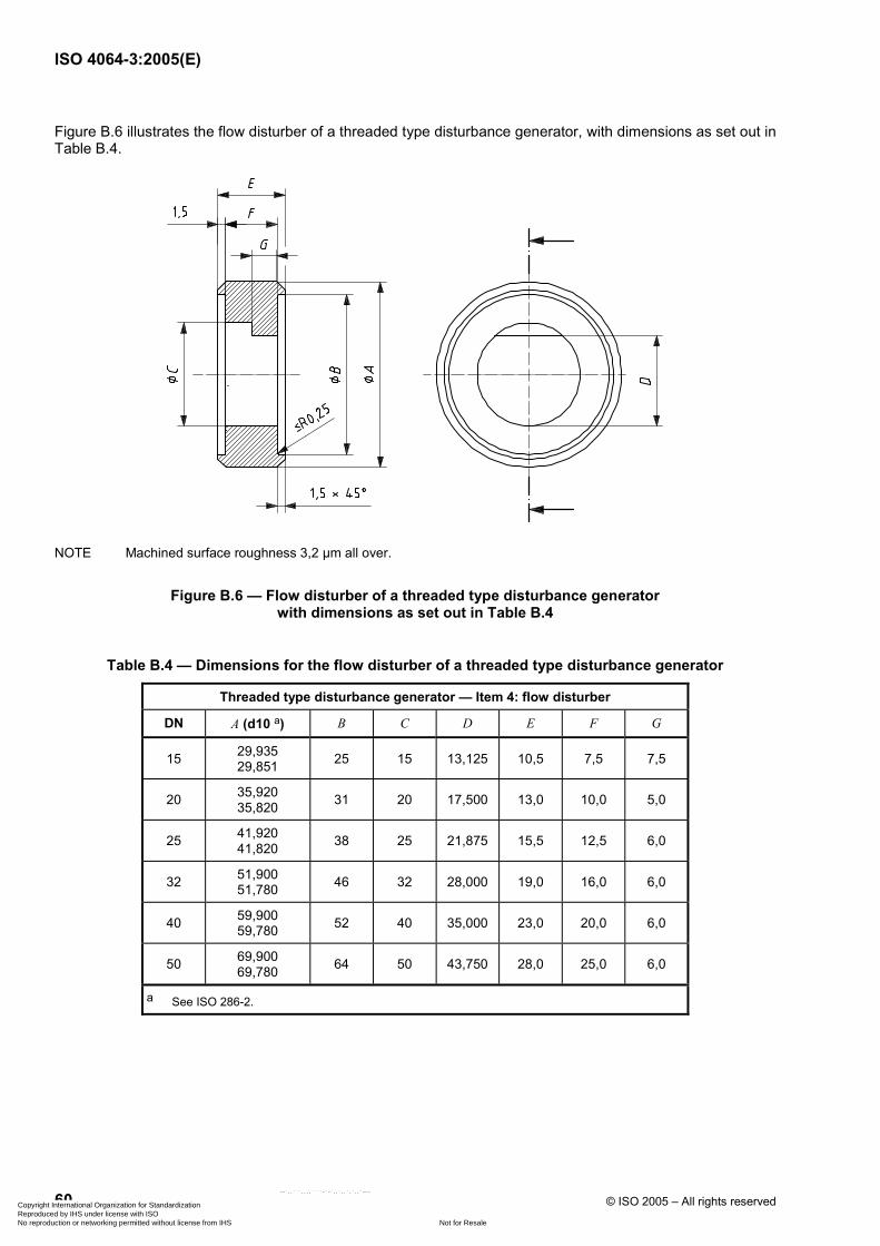
ISO 4064-3:2005(E)
60 © ISO 2005 – All rights reserved
Figure B.6 illustrates the flow disturber of a threaded type disturbance generator, with dimensions as set out in Table B.4.
NOTE Machined surface roughness 3,2 µm all over.
Figure B.6 — Flow disturber of a threaded type disturbance generator with dimensions as set out in Table B.4
Table B.4 — Dimensions for the flow disturber of a threaded type disturbance generator
Threaded type disturbance generator — Item 4: flow disturber
DN A (d10 a) B C D E F G
15 29,935 29,851 25 15 13,125 10,5 7,5 7,5
20 35,920 35,820 31 20 17,500 13,0 10,0 5,0
25 41,920 41,820 38 25 21,875 15,5 12,5 6,0
32 51,900 51,780 46 32 28,000 19,0 16,0 6,0
40 59,900 59,780 52 40 35,000 23,0 20,0 6,0
50 69,900 69,780 64 50 43,750 28,0 25,0 6,0
a See ISO 286-2.
Copyright International Organization for Standardization Reproduced by IHS under license with ISO
Not for ResaleNo reproduction or networking permitted without license from IHS
--`,,```,,,,````-`-`,,`,,`,`,,`---

ISO 4064-3:2005(E)
© ISO 2005 – All rights reserved 61
Figure B.7 illustrates the gasket of a threaded type disturbance generator, with dimensions as set out in Table B.5.
Figure B.7 — Gasket of a threaded type disturbance generator with dimensions as set out in Table B.5
Table B.5 — Dimensions for the gasket of a threaded type disturbance generator
Threaded type disturbance generator — Item 5: gasket
DN A B
15 24,5 15,5
20 30,5 20,5
25 37,5 25,5
32 45,5 32,5
40 51,5 40,5
50 63,5 50,5
Copyright International Organization for Standardization Reproduced by IHS under license with ISO
Not for ResaleNo reproduction or networking permitted without license from IHS
--`,,```,,,,````-`-`,,`,,`,`,,`---

ISO 4064-3:2005(E)
62 © ISO 2005 – All rights reserved
B.3 Wafer type disturbance generators
Figure B.8 shows an arrangement of swirl generator units for a wafer type disturbance generator.
Item No. Description Quantity Material
1 Swirl generator 1 Stainless steel
2 Flow — —
3 Gasket 2 Fibre
4 Straight length with flange (see ISO 7005-2 or ISO 7500-3) 4 Stainless steel
(Type 1 disturber — Swirl generator sinistrorsal; Type 2 disturber — Swirl generator dextrorsal)
Figure B.8 — Wafer type disturbance generator — Arrangement of swirl generator units
Copyright International Organization for Standardization Reproduced by IHS under license with ISO
Not for ResaleNo reproduction or networking permitted without license from IHS
--`,,```,,,,````-`-`,,`,,`,`,,`---

ISO 4064-3:2005(E)
© ISO 2005 – All rights reserved 63
Figure B.9 shows an arrangement of velocity profile disturbance units for a wafer type disturbance generator.
Item No. Description Quantity Material
1 Flow disturber 1 Stainless steel
2 Flow – —
3 Gasket 2 Fibre
4 Straight length with flange (see ISO 7005-2 or ISO 7500-3) 4 Stainless steel
(Type 3 disturber — Velocity profile flow disturber)
Figure B.9 — Wafer type disturbance generator — Arrangement of velocity profile disturbance units
Copyright International Organization for Standardization Reproduced by IHS under license with ISO
Not for ResaleNo reproduction or networking permitted without license from IHS
--`,,```,,,,````-`-`,,`,,`,`,,`---

ISO 4064-3:2005(E)
64 © ISO 2005 – All rights reserved
Figure B.10 illustrates the swirl generator of a wafer type disturbance generator, with dimensions as set out in Table B.6.
Key 1 8 slots equally spaced to locate blades 2 blades to be fixed in (welding)
a D holes of ∅ E.
Figure B.10 — Swirl generator of a wafer type disturbance generator with dimensions as set out in Table B.6
Copyright International Organization for Standardization Reproduced by IHS under license with ISO
Not for ResaleNo reproduction or networking permitted without license from IHS
--`,,```,,,,````-`-`,,`,,`,`,,`---

ISO 4064-3:2005(E)
© ISO 2005 – All rights reserved 65
Table B.6 — Dimensions for the swirl generator of a wafer type disturbance generator
Wafer type disturbance generator — Item 1: swirl generator
DN A B C D E F G H J K L M N P R
50 50 165 104 4 18 125 45° 25 28 16,9 25,5 1,5 1,57 1,52
− −
65 65 185 124 4 18 145 45° 33 36 21,9 33,4 1,5 1,57 1,52
− −
80 80 200 139 8 18 160 22 1/2 ° 40 43 26,9 40,6 1,5 1,57 1,52 − −
100 100 220 159 8 18 180 22 1/2 ° 50 53 33,6 50,8 1,5 1,57 1,52 − −
125 125 250 189 8 18 210 22 1/2 ° 63 66 41,9 64,1 1,5 1,57 1,52
− −
150 150 285 214 8 22 240 22 1/2 ° 75 78 50,3 76,1 3,0 3,07 3,02
195 22
200 200 340 269 8 22 295 22 1/2 ° 100 103 66,9 101,6 3,0 3,07 3,02 245 24
250 250 395 324 12 22 350 15° 125 128 83,6 127,2 3,0 3,07 3,02 295 26
300 300 445 374 12 22 400 15° 150 153 100,3 152,7 3,0 3,07 3,02
345 28
400 400 565 482 16 27 515 11 1/4 ° 200 203 133,6 203,8 3,0 3,07 3,02
445 30
500 500 670 587 20 27 620 9° 250 253 166,9 255,0 3,0 3,07 3,02 545 32
600 600 780 687 20 30 725 9° 300 303 200,3 306,1 3,0 3,07 3,02 645 34
800 800 1 015 912 24 33 950 7 1/2 ° 400 403 266,9 408,3 3,0 3,07 3,02
845 36
Copyright International Organization for Standardization Reproduced by IHS under license with ISO
Not for ResaleNo reproduction or networking permitted without license from IHS
--`,,```,,,,````-`-`,,`,,`,`,,`---

ISO 4064-3:2005(E)
66 © ISO 2005 – All rights reserved
Figure B.11 illustrates the flow disturber of a wafer type disturbance generator, with dimensions as set out in Table B.7.
NOTE Machine surface tolerance 3,2 µm all over.
a D holes of ∅ E.
Figure B.11 — Flow disturber of a wafer type disturbance generator with dimensions as set out in Table B.7
Copyright International Organization for Standardization Reproduced by IHS under license with ISO
Not for ResaleNo reproduction or networking permitted without license from IHS
--`,,```,,,,````-`-`,,`,,`,`,,`---

ISO 4064-3:2005(E)
© ISO 2005 – All rights reserved 67
Table B.7 — Dimensions for flow disturber of a wafer type disturbance generator
Wafer type disturbance generator — Item 2: flow disturber
DN A B C D E F G H
50 50 165 104 4 18 125 45º 43,8
65 65 185 124 4 18 145 45º 56,9
80 80 200 139 8 18 160 22 1/2 ° 70,0
100 100 220 159 8 18 180 22 1/2 ° 87,5
125 125 250 189 8 18 210 22 1/2 ° 109,4
150 150 285 214 8 22 240 22 1/2 ° 131,3
200 200 340 269 8 22 295 22 1/2 ° 175,0
250 250 395 324 12 22 350 15º 218,8
300 300 445 374 12 22 400 15º 262,5
400 400 565 482 16 27 515 11 1/4 ° 350,0
500 500 670 587 20 27 620 9 ° 437,5
600 600 780 687 20 30 725 9 ° 525,0
800 800 1 015 912 24 33 950 7 1/2 ° 700,0
Copyright International Organization for Standardization Reproduced by IHS under license with ISO
Not for ResaleNo reproduction or networking permitted without license from IHS
--`,,```,,,,````-`-`,,`,,`,`,,`---

ISO 4064-3:2005(E)
68 © ISO 2005 – All rights reserved
Figure B.12 illustrates the gasket of a wafer type disturbance generator, with dimensions as set out in Table B.8.
Figure B.12 — Gasket of a wafer type disturbance generator with dimensions as set out in Table B.8
Table B.8 — Dimensions for the gasket of a wafer type disturbance generator
Wafer type disturbance generator — Item 3: gasket
DN A B
50 103,5 50,5
65 123,5 65,5
80 138,5 80,5
100 158,5 100,5
125 188,5 125,5
150 213,5 150,5
200 268,5 200,5
250 323,5 250,5
300 373,5 300,5
400 481,5 400,5
500 586,5 500,5
600 686,5 600,5
800 911,5 800,5
Copyright International Organization for Standardization Reproduced by IHS under license with ISO
Not for ResaleNo reproduction or networking permitted without license from IHS
--`,,```,,,,````-`-`,,`,,`,`,,`---

ISO 4064-3:2005(E)
© ISO 2005 – All rights reserved 69
Annex C (informative)
Manifold — Examples of methods and components used for testing
concentric water meters
Figure C.1 shows an example of a manifold connection for a concentric water meter.
Key 1 concentric water meter 2 concentric water meter manifold (part view)
a Water flow out. b Water flow in.
Figure C.1 — Example of a manifold connection for a concentric water meter
A special pressure test manifold, such as that shown in Figure C.2, may be used to test the meter. To ensure that the seals are operating at their “worst case” during the test, the pressure test manifold sealing face dimensions
Copyright International Organization for Standardization Reproduced by IHS under license with ISO
Not for ResaleNo reproduction or networking permitted without license from IHS
--`,,```,,,,````-`-`,,`,,`,`,,`---

ISO 4064-3:2005(E)
70 © ISO 2005 – All rights reserved
should be at the appropriate limits of the manufacturing tolerances in accordance with the design dimensions specified by the manufacturer.
Before being submitted for pattern approval, the meter manufacturer may be required to seal the meter at a point above the location of the inner seal of the meter/manifold interface, by a means suited to the meter design. When the concentric meter is fitted to the pressure test manifold and pressurized, it is necessary to be able see the source of any leak flowing from the pressure test manifold outlet and to distinguish between it and that issuing from an incorrectly fitted sealing device. Figure C.3 shows an example of a design of plug suited to many meter designs, but any other suitable means may be used.
Key 1 pressure 2 position of inner seal
a Path of leakage water passing seal.
Figure C.2 — Example of a manifold for pressure testing concentric meter seals
Copyright International Organization for Standardization Reproduced by IHS under license with ISO
Not for ResaleNo reproduction or networking permitted without license from IHS
--`,,```,,,,````-`-`,,`,,`,`,,`---

ISO 4064-3:2005(E)
© ISO 2005 – All rights reserved 71
a) Section through meter and manifold showing test plug in position
b) Detail of test plug
Key 1 meter outer seal 6 O-ring grooves 2 meter 7 tapping for withdrawal bolt 3 meter inner seal 8 4-6 gashes, equi-spaced 4 test plug 9 “Witness” leakage hole 5 manifold
a Pressure.
Figure C.3 — Example of a plug for pressure testing concentric meter seals
Copyright International Organization for Standardization Reproduced by IHS under license with ISO
Not for ResaleNo reproduction or networking permitted without license from IHS
--`,,```,,,,````-`-`,,`,,`,`,,`---

ISO 4064-3:2005(E)
ICS 91.140.60 Price based on 71 pages
© ISO 2005 – All rights reserved
Copyright International Organization for Standardization Reproduced by IHS under license with ISO
Not for ResaleNo reproduction or networking permitted without license from IHS
--`,,```,,,,````-`-`,,`,,`,`,,`---