measurement of thin film parameters with a prism couplerfemtosecondsystems.com/coupling_prism/ulrich...
TRANSCRIPT

Measurement of Thin Film Parameters with aPrism CouplerR. Ulrich and R. Torge
The prism coupler, known from experiments on integrated optics, can be used to determine the refractiveindex and the thickness of a light-guiding thin film. Both parameters are obtained simultaneously andwith good accuracy by measuring the coupling angles at the prism and fitting them by a theoretical dis-persion curve. The fundamentals and limitations.of this method are discussed, its practical use, andmathematical procedures for the evaluation.
1. IntroductionIn various experiments on integrated optics,' thin
dielectric films are used as planar light guides. Themain parameters characterizing such films are therefractive index n and the film thickness W. For thedetermination of these parameters, numerous meth-ods are possible. One method that is particularlywell adapted to this problem is the prism couplingtechnique.2 -4 It can give accurate results simplyand fast, and a prism coupler is often used anywayin such experiments.
In brief, this method works as follows. The cou-pling of a laser beam by a prism into a planar dielec-tric light guide is governed 2 -5 by the angle 0 of inci-dence of the light onto the prism base (Fig. 1). Thisangle 6 determines the phase velocity in x direction,vi = c/n, sinO, of the incident wave in the prism(index np) and in the gap. Strong coupling of lightinto the film occurs only when we choose 0 so thatU(i) equals the phase velocity Um of one of the char-acteristic modes of propagation in the guide (m =0,1,2 . . .). Thus, by determining these synchronousangles O9m of strongest coupling, we can find experi-mentally the characteristic propagation constants ofa given film, relative to the propagation constant k= co/c of free space
] Nm = c/Urn = np sinkm. (1)
On the other hand, we can calculate theoreticalvalues Nm for the relative propagation constants
M. Ulrich is with Max-Planck-Institut fur Festkbrperforschung,7 Stuttgart, Germany; R. Torge is with Forschungsgruppe, CarlZeiss, 7082 Oberkochen, Germany.
Received 23 April 1973.
from the known dispersion equation of a planar di-electric light guide:
Nm = N(m, n, W, k, no, n 2, P). (2)
Details of this calculation are in the Appendix. InEq. (2), no and n2 are the refractive indices of thetwo media adjacent to the film (Fig. 1), and by p weindicate the polarization of the laser beam (p = 0 forTE polarization, and p = 1 for TM). All these pa-rameters are known or can be measured separately.Therefore, it remains a computational problem toadjust the two unknown parameters n and W untilthe resulting theoretical values Nm match as closelyas possible the experimental values Nm. We regardthose parameters fi and W, for which the match isbest, as the results of this method.
In comparison with other methods, the one de-scribed here has two important advantages: (1) itrequires only the measurement of angles, which canbe done conveniently and with high precision; (2) ifthe film is thick enough to allow the observation ofmore than two modes of the same polarization, themethod becomes a self-consistent one because thetwo unknowns n and W are then determined frommore than two independent measurements. Thisimproves the accuracy and greatly increases the con-fidence in the results.
There are, of course, also a number of disadvan-tages to this method that limit its applicability: (1)The film must be thick enough to permit the propa-gation of at least two modes. If only one mode canbe observed, we may still use the prism coupler todetermine one of the parameters n and W if theother is known from an independent measurement.(2) For reasons of convenient observation, a mono-chromatic laser beam should be available as the lightsource at the wavelength at which n is to be deter-mined. (3) Because it is usually necessary to pressthe film mechanically against the base of the prism,the method does not work contactless. Yet, if care
December 1973 / Vol. 12, No. 12 / APPLIED OPTICS 2901

Z SCREENI PRISM p
GAP
n .. : ~~~~~~~..- .. . :...:.: :: :..F
Fig. 1. SUheaticrossctinthou BSTRATE
Fig. 1. Schematic cross section through a prism-film coupler.
SCREEN, FIXED% TO TABLE
APERTURES +
POLARIZERLENS
WAXY- STAGE.- ROTATABLE
TABLE'CLAMPING -SCREW
Fig. 2. Schematic arrangement of prism, input optics, and ob-servation screen. The double arrows indicate adjustments.
is taken, the measurement is not destructive, either.In this respect, the method is obviously suited betterfor hard films than for soft films. (4) Finding thecoupling angles requires a certain degree of skill andexperience. Difficulties may occur due to excessivelosses in the films, causing a broadening of themodes beyond recognition. Typically, an absorptionup to 20 cm-' in the direction of propagation (or 80dB/cm) is tolerable, although it will already reducesomewhat the accuracy of the measurement. (5)The evaluation of the measurements requireslengthy, although simple, calculations. Therefore,the method is practical only where a programmablecomputer is available.
11. Experimental Technique
A. General Arrangement
The experimental arrangements for the observa-tion of the coupling and for the measurement of thecoupling angles is shown schematically in Fig. 2. Bymeans of a spring-loaded clamp, the film under testis pressed against the base of a coupling prism. Theprism can be either symmetric [Fig. 3(a)] or a half-prism [Fig. 3(b)]. It sits on an xy translation stagethat is mounted on a precision (<1 min of arc) rota-ry table or goniometer. Also mounted on the rotarytable is an Qbservation screen for use with the sym-metric prism. The laser beam is linearly polarized(TE or TM) and must be of TEMoo cross section. Alens focuses the beam into the prism so that thebeam waist coincides with the prism base. The
point where the beam strikes the prism base is thecoupling spot. At this point, the parameters n andW are being measured. In the case of a symmetricprism the coupling spot is preferably near the centerof the prism base; in a half prism it must be close tothe corner.
The optical system is adjusted so that the couplingspot remains practically stationary on the prism basewhen the rotary table is rotated through the angularrange where coupling is possible. This adjustmentrequires the direction of the input beam to be point-ing slightly off the axis of the rotary table and theprism to be positioned suitably by means of the xytranslation stage. Nearly perfect stationarity can beobtained with one fixed adjustment only for therange a > 0 of input angles [Fig. 4(a)], while a differ-ent fixed adjustment works for the range a < 0 [seeFig. 4(b)]. For the first range a > 0 the laser beammust be offset from the axis of the table by approxi-mately p/np toward the top of Fig. 2 and for a < 0by the same amount toward the bottom of that fig-ure. Here 1p is the length of the path of light insidethe prism from the entrance face to the couplingspot, measured near a = 0.. The prism must be ad-justed so that it has the positions indicated in Fig. 4relative to the axis of rotation. For a good stationa-
(a) {,t- ( b)
Fig. 3. Two possible prism shapes: (a) symmetric prism, usefulwith samples that are slightly flexible (e.g., glass substrates 1mm) and yield elastically under the clamping pressure; (b) halfprism, may also be used with thick samples because the coupling
spot is close to the edge.
cc > B
BEAM BrC
7B EBEAM r
(a) ( b)
Fig. 4. Arrangement to keep the coupling spot stationary at Cwhen the prism is rotated. The line CD is normal to AB and haslength l1. The axis of the rotary table coincides with the centerM of the dashed circles. The radius of these circles is r = /n,where n is the refractive index of the prism. The adjustment isoptimum when the lines AB and CD and the incident beam areall tangential to the circles. This requires the beam to be offsetby r from the axis of the table, and this offset must be toward B
if a > 0 as indicated in (a), but toward A if a < 0 [see (b)].
2902 APPLIED OPTICS / Vol. 12, No. 12 / December 1973
n2 I I

rity it is furthermore advantageous for the prism tobe small (for example, 1p <5 mm) and have a highrefractive index and for the lens to have a long focallength (for example, f > 250 mm) so that the cou-pling spot is not too small. A correct adjustment forstationarity is particularly important if the measuredfilm does not have a uniform thickness.
Before performing the actual measurements wescan several times through all modes to watch theirappearance and to identify the mode numbers. Themode with the largest angle a of incidence has thelowest mode number. If the measuring range of theprism is wide enough, this is m = 0. For such a sur-vey of the modes, it is best to use a fairly highclamping pressure. In the actual measurement,then, the readings rm of the rotary table that givethe best coupling are noted. For the reasons givenin Sec. III, it is necessary in taking each of thesereadings to reduce the clamping pressure to the min-imum value that still permits an accurate determi-nation of Tm. With high-quality films the angles Tmcan be set reproducibly to within less than 1 min ofarc. Because the different modes are measured atdifferent clamping pressures, it is essential that theprism is mounted firmly so that it does not twist orrotate when the clamping pressure is changed. Fora calibration of the zero point of the angular scale wedetermine also the reading F l of that angle atwhich the beam is incident normally on the entranceface of the prism, i.e., where the reflection from thefront face of the prism goes back exactly into the in-cident beam. The actual angles of incidence on theentrance face of the prism are
am = +(rm - l), (3)
where the + or - sign applies depending on whetherthe scale on the turntable increases clockwise or an-ticlockwise.
B. Observation of the ModesThe coupling of the laser beam into the film can
be observed in various ways, depending on the char-acteristics of film and substrate and on the type ofprism used. Many evaporated or sputtered filmswith minute roughness or inhomogeneities (e.g.,ZnS, ZnO, A12 03 , CeO2 ) may be measured with thesymmetric prism, especially when they are depositedon thin substrates that are slightly flexible [Fig. 3(a) ].In this case the coupling can usually be observed bythe appearance of a streak of guided light in the filmand simultaneously by the appearance of bright ordark m-lines2 on the screen in Fig. 2. In some high-ly attenuating films, the streak of guided light maybe so short that it can hardly be observed at all.Frequently, in such cases, however, the scattering isstill strong enough so that the coupling spot itselfshows a sudden increase in brightness when theprism is rotated through one of the coupling angles.This is sufficient to determine the positions Tm alsoin such highly scattering films.
The bright m-lines appear on the screen only when
the laser beam is coupled into a mode of the film.The light propagating in that mode is scattered intoother directions (in the plane of the film) of the samemode and of the other modes. A fraction of thescattered light is then coupled out again by theprism and produces the bright lines on the screen.In accordance with this explanation it is character-istic for the bright m-lines that they all light up si-multaneously when, during rotation of the prism,one of the coupling directions m passes through thedirection of the input beam. Moreover, in each ofthese coupling situations, the reflected beam on thescreen coincides with one of the m-lines. Occasion-ally, one can also observe dark m-lines. On thescreen, they appear in the weak background of lightscattered at various roughnesses of the prism, partic-ularly at its entrance face. This scattered light hasa broad angular distribution, and it would illuminatethe screen nearly uniformly. Scattered light, how-ever, which propagates in directions inclined at oneof the coupling angles m with respect to the filmnormal, is coupled into the film. There, it may sub-sequently be guided away from the coupling spot, orit may be absorbed. Hence, light of these directionsis missing from the nearly uniform illumination ofthe screen, thus causing the dark m-lines. From theabove explanation it is clear that the dark m-linesappear at the same positions on the screen as thebright m-lines. Bright vertical lines on the screenmay also be caused by scattering of the laser beamat horizontal polishing scratches on the prism faces.Such lines can be distinguished, however, from them-lines by the fact that only the latter ones havefixed angular positions with respect to the prism.
Films with very smooth surfaces, like the organosi-licon films6 and many solution-deposited films, 7 donot show the bright m-lines in an arrangement likeFig. 2 because their scattering is too weak. Thesefilms are measured best by observing the intensity ofthe streak of guided light. Again, with films onslightly flexible substrates either type of prism ofFig. 3 may be used. The clamping pressure maycause a slight deformation of the films, resulting in atapered coupling gap. As long as this taper is weak(angle <10-4), it is no disadvantage. Rather, itmay yield a slightly higher coupling efficiency than auniform gap.8 Smooth films on thick substrates areusually measured best with the half-prism [Fig.3(b)].
C. Prism
Besides the prism shape (Fig. 3), the most impor-tant parameters of a coupling prism are its refractiveindex np and the prism angle e. They determine therange of propagation constants N that can be mea-sured with the prism. The propagation constant N= np sinG of the light along the prism base is relatedto the angle a of incidence on the entrance face ofthe prism (Fig. 1) by
N = sina cosE + (np2 - sin2 a)1/2 sine. (4)
December 1973 / Vol. 12, No. 12 / APPLIED OPTICS 2903

4
3
2
0 0 10 20 30 40 50 60 70 80 90°
Fig. 5. Range of relative propagation constants N that can bemeasured with a prism of prism angle e. Parameter at the curvesis the prism index np,. For each value of np there are two curves,
giving the lower and upper limits of the possible N range.
If we let a vary from -7r/2 to +7r/ 2 , we obtain therange of N-values possible with a given prism. Wehave shown the limits Nmin and Nmax of this rangein Fig. 5 for a number of prism indices. In a film ofindex n, deposited on a substrate of index no, allguided modes (m = 0,1,2, .. .) are in the interval no< N < n. Therefore, in order to measure allmodes of this film, a prism is required in generalwhose N range covers the inverval from no to n. Inpractice, the N range read from Fig. 5 must even beslightly wider than from no to n, because in the lim-its of grazing incidence (a - 47r/ 2 ), the usable crosssection of the beam vanishes. The choice of Nminmay also be governed by the necessity to measure in-dividually the index np of the completed couplingprism. This index enters through Eq. (4) into theevaluation, and therefore, it should be known veryaccurately. It can be determined conveniently bythe method of minimum deviation, provided thatone of the prism angles is so small that the associ-ated Nmin < 1. Finally, if possible, one may wantto choose the prism angle so that the N range of in-terest does not contain the case of normal incidencec = 0 where the adjustment for a stationary couplingspot must be changed.
These considerations yield in practice prism anglesfrom about 30° to 60°, depending on the index. Inorder to cover a very wide N range, it may be neces-sary to use two or even three prisms. Practical ex-perience with various prisms has shown that it is ad-vantageous to have none of the prism angles equal to300, 450, 600, 900, or other small-integer fractions of3600, or multiples thereof. Rather, one should stay
about 1 away. from these angles, so that reflexesfrom the (uncoated) prism faces do not interfere withthe main beam. This recommendation includes thelargest angle of the half-prism [Fig. 3(b)]. Thatangle is preferably made slightly larger than 90 togive a clear angular separation of the incident andreflected beams. The edge at that angle should befairly sharp, because a rounded edge here can causea wide horizontal fan of scattered light that may il-luminate the film in a manner resembling a guidedstreak.
The prism material should be as hard as possibleto avoid damaging the prism base by repeatedlypressing films on it. Some suitable materials are thevarious high-index glasses, crystals like SrTiO3 andTiO2 (rutile), and Si and Ge for the ir. In the caseof rutile, a uniaxial birefringent crystal, the opticalaxis should be oriented parallel to the edge of theangle E. Only this orientation allows us to use inEq. (4) a constant index n, which is the ordinaryindex for TM polarization, and the extraordinaryindex for TE. It need hardly be mentioned that theprism faces enclosing the angle E should have a goodoptical polish. They must be flat to about /2 inorder to define the angle E with sufficient accuracy.
The prism may be replaced, in principle, by ahemispherical cylinder. The input beam then wouldpass the cylindrical surface at nearly normal inci-dence for all angles , thus extending the N rangeand simplifying the evaluation. An analysis of thehemispherical coupler shows, however, that it is crit-ical with respect to small lateral displacements ofthe input beam, which must point exactly to thecenter of the cylinder. The prism-coupler, in com-parison, is insensitive to parallel displacements ofthe input beam or of the prism.
Ill. Importance of Weak CouplingIt had been mentioned that for taking the final
readings of the mode angles Fm, the clamping pres-sure must be reduced with each mode as far as possi-ble without loosing the mode. The reason is that ahigh pressure, i.e., strong coupling, broadens themodes and may shift them. We will show now thatthese effects become negligible when the couplingpressure is reduced to far below its value for opti-mum power transfer into the film. Furthermore, wewill obtain an estimate of the accuracies possible inthe determination of n and W by the prism-couplermethod.
We first consider the question of mode broadeningdue to the prism. The coupling efficiency into thefilm is given theoretically 5 ,8 by the overlap integralof the input field V3(x) with an output functionQm(x). This function describes the output field ofthe coupler in a situation where a guided wave in themth mode is fed into the coupler from the right ofFig. 1. Associated with Qm is a certain radiationpattern of the output light. The main lobe of thispattern has an angular width that can be expressedin the N-scale as N2 X/wQ. Here w is the spa-
2904 APPLIED OPTICS / Vol. 12, No. 12 / December 1973

tial width of the output field Qm(x), measured alongthe guide. According to the reciprocity theorem forantennas, the radiation pattern also acts as the re-ceiving pattern of the coupler when used for inputinto the guide. Hence 3No is also the angular inputaperture of the coupler, and it may be comparedwith the angular aperture 6N = n cosG 601 of theincident laser beam. Here 6G, is the angular beamspread measured inside the prism. When the cou-pler is rotated for the measurement of the m, amode can be observed in the film throughout an an-gular interval that corresponds to the larger one of6NQ and AN,. While the beam aperture 6N, is prac-tically fixed, we can vary the aperture of NQ of theinput pattern by adjusting the clamping pressure.We obtain the largest net power transfer (80%)into the film when both apertures have about equalwidths.5 If we reduce the clamping pressure, start-ing from this condition, until only a small fraction ofthe laser power enters the film, the input pattern ofthe coupler is much narrower than the aperture ofthe laser beam bNo << AN,. The observed angularwidths of the modes are then equal to the angularaperture 3Gs of the laser beam. The broadening dueto the prism has become negligible.
The other disturbing influence of too strong cou-pling is a shift of the modes due to the presence ofthe prism in the vicinity of the film. According toRef. 5, this shift can be expressed as
N,'P)- Nm = -Km cot2 32. (5)
Here the superscript (p) is used to indicate the influ-ence of the prism. Km is the leak rate of the cou-pler, and it can be shown that
Km 2-6NO.
The angle 2032 in Eq. (5) is the phase of the total in-ternal reflection at the prism base. 5 From Eq. (5) itfollows that the mode shift vanishes as the couplingpressure is reduced and ANu - 0, provided the factorcot2k32 remains finite. This factor diverges onlywhen N - n2 or N - np,. The first case does notoccur in practice with films on a substrate becausen2 usually is free space so that N > no > n2 . In theother limit N - np, we find
cot2 32 < (np/n 2 )2 P/2 cos8.
This expression is bounded because we have to stayaway from grazing incidence 0 - 90° anyway. If wekeep 0 < 700, for example, we have in a rutile prismcot232 < 1.6 for TE polarization (np = ne0 = 2.86)and cot2G32 < 10 for TM (np = no = 2.58).
IV. AccuracyThe preceding considerations may also help obtain
an idea of the accuracy with which the index n of afilm can be determined. For films of low attenua-tion, the accuracy in measuring the mode positions islimited by the aperture AN, of the input beam.Near normal incidence on the prism a 0, we have5N, ~ cosfba, where ea is the angular aperture of
the laser beam outside the prism. By visual obser-vation, the mode positions can be determined towithin some fraction of AN,, typically N1/3. There-fore, we may regard the value N1/3 as the approxi-mate accuracy n obtainable for the film index n.As an example, we consider a laser beam of 1-mmdiam, focused by a lens of f = 500 mm into a prismof e = 450. Here we have ea = 0.002 and AN,0.0014, so that n should be measurable to an accura-cy of 6n 0.0005. If several modes are observedand multiple readings are taken, an accuracy of An
0.0001 can be obtained in practice. This is dem-onstrated in Sec. VI. It is interesting to note thatthis accuracy is obtained by measuring a film areawhose length is diffraction limited by the beam aper-ture a, the width of the coupling spot being w, X/bNI P, /cos ba. In the above example, we havew, P.:500 Am. It follows, furthermore, that the at-tenuation of the guide over the distance w, must notbe too high. If we denote the power attenuationcoefficient by A, the accuracy of the measurementsbegins to be seriously degraded when Awe > 1. Inour example, this limit is at A = 20 cm-' or 80 dB/cm.
We estimate the accuracy in the determination ofthe film thickness W from the relation W ;6n(aW/dN)m. Here we take the derivative at con-stant indices and fixed wavelength for a mean modenumber n. For a not-too-thin film and no > n2, thetotal number of modes of one polarization is of.theorder
Mtot V Vr-'kW(n2 - n,2)1/2 (6)
and we take = Mtot/2. The corresponding meanpropagation constant N is, in the same approxima-tion, given by N2 = (no2 + 3n2 )/4, and we obtainafter further simplification
6W/W 2n/(n - no). (7)
This formula shows that the possible accuracy of thefilm thickness is reduced for films of low index differ-ences (n - no). In the example to be discussed inSec. VI, we have (n - no) 0.15 and n 0.00020,and Eq. (7) would predict an accuracy of W/W 0.0025. The actual error found in Sec. VI is aboutfour times higher.
V. Evaluation of Film Index and ThicknessThe results of the measurements are a list contain-
ing the observed modes of the film, identified bytheir mode numbers m = 0,1,2 ... , and for eachmode the measured coupling angle Fm. For simplic-ity, we assume that all modes have the same polar-ization. The modes of the other polarization may betreated correspondingly, providing a good check onthe results of the first polarization. These pairs(mm), together with the constant parameters ofthe measurement (F 1 ,no,n2,E,np,X,p), are fed into acomputer. It first calculates and prints out the setof observed propagation constants, Nm, using Eqs.(3) and (4). The further evaluation depends on
December 1973 / Vol. 12, No. 12 / APPLIED OPTICS 2905

whether the number M of observed modes in the listis M = 2 or M > 3. In the case of M = 2, a relative-ly simple procedure yields unique values n and W.If M > 3, a more lengthy least square fit of the ob-servations is used to calculate "best" values n and Wof film index and thickness together with their rmsdeviations.
A. Two Observed ModesThe mode numbers of the two modes are called ,
and v. Usually these will be 0 and 1, but we mayallow here 4 and v to be any two modes of equal po-larization. The observed propagation constants N,and Nv are related to the unknown n and W by thedispersion equation of the planar dielectric guide.We write this equation as
kW(n2 - N 2)"2 = 'mfn, Nm), (8)
where
'Im(n, Nm)- mar + Q0(n, Nm) + 02(n, Nm) (9)
and
Oj(n, Nm) i arctan[( ) 2(m - J (10)
with j = 0,2. Inserting N" and N, into Eqs. (8)-(10)yields two equations from which k W can be elimi-nated. The resulting single equation for n may bewritten in the form
n2= F(n2 ), (1)
with
F(n2 ). E(NU2 V2 - N\2U2 )/(V2 _ 2). '(12)
Equation (11) cannot be solved explicitly for n2 , buta solution is readily found by iterating this equation.We thus calculate the series [q
2 for q = 1,2,3 . .. bythe recursion formula
n[q]2 = F(n[q-1]2). (13)
This series converges to the required solution
n2 = lim n[q]2,q-- O.
provided that I F/a(n2) < 1. Because we could notverify this inequality analytically, we have studiedthe convergence of the iteration Eq. (13) numericallyfor a very wide range of arguments, including allpossible situations of practical interest. We foundthat Eq. (13) did converge in all cases, provided thatthe first term n o 2 of the series satisfied tie relations
n[l]2 > N'2 and n[o]2 > N.
This is physically reasonable and can always beguaranteed by a suitable choice of the initial termn O2. We have used, for example, n1 2 = 1.1NU2,where N > N was guaranteed by sorting the modesby ascending mode numbers, i.e., descending Nm.The convergence of the series Eq. (13) has an oscil-
latory character, reaching an error of less than 10-6after typically ten to twenty steps. The iteration isinterrupted after the change of n [q 2 in one step fallsbelow some limit (e.g., 10-6) depending on the nu-merical accuracy of the computer. With n thusknown, we obtain the film thickness W directly fromEq. (8).
B. Three or More Observed ModesIf the number of observed modes is M 2 3, the two
unknowns n and W are overdetermined. (M - 2) ofthe M measurements are redundant and may beconsidered as providing checks on the validity of theother two. If a larger number of modes has beenmeasured, e.g., M = 5 - 10, we can therefore obtainexperimentally a good idea of the self-consistency ofthe measurements and of the accuracy of ft and W ofa given film.
For the evaluation we define an error sum
a(n, w) = [Nm - Nm(f, W)]2.m[ . - .n (14)
Here the Nm are the observed propagation constants,whereas the Nm(n,w) are the solutions of the disper-sion Eq. (8) for a given combination of film indexand thickness. Details of computing Nm(n,w) aregiven in the Appendix. In Eq. (14) we have intro-duced the dimensionless variable w = kW instead ofthe physical thickness W. The summation in Eq.(14) runs over all M observed modes. We have de-fined the error sum a- using the relative propagationconstants N. More strictly, if all measurementswere done with the same angular accuracy, the errorsum should be formed with the calculated and ob-served angles m. However, the use of the N in-stead of the m gives us a simpler formulation at theprice of slightly different statistical weights of themeasurements.
The best values and a) are those that minimizethe error sum. Necessary conditions for the mini-mum are
on(n, ) = 0 and (n, w) = 0, (15)
where the subscripts indicate the partial derivativeswith respect to n or w, respectively. Equations (15)cannot be solved analytically for ft and becausethe dispersion N(n,w) cannot be expressed inclosed form (see Appendix). Therefore, we deter-mine a solution numerically by a gradient method:We assume that an approximate solution n andw rq] is already known. We expand a formally into apower series up to second order terms around a pointPfq] = n[q], w[qJ in the n,w plane, and we insertthis series into the Eqs. (15). We obtain an im-proved solution Pq+lj by progressing from Prq] asuitable distance in the direction of the negative gra-dient of a(nw)
2906 APPLIED OPTICS / Vol. 12, No. 12 / December 1973
Tlq+l] = n[q] + C.U. - an, )/det,
W[q+l] = [q] + (a-nnw - awann)/ldet,
det (annaww - anwa-wn).
(16) the observed Nm. These thicknesses are found di-rectly from Eq. (8). The resulting rms errors of
(17) and tv are then
(18)
The derivatives appearing here are all required atP[u . For the numerical calculation they are approx-imated by their corresponding central differences
a,, = [a-(1,0) - a(-1,0)]/2h,,,
a = [(0,1) - a(0, -1)]/2hx,
-n,, = [a-(iO) - 2a(0,0) + a-(-1,O)]/hn,
aw. = [(0,1) - 2a(0,0) + (0,-1)]/h2,
anw = wn [a-(i,) - a(-1,1) - a(1, -1)
+ a(-l,-1)4hnhw. (19)
We have used here an abbreviated notation for thenine argument combinations at which the error suma- has to be evaluated
a(r,s) = a(n[q] + rh,.,W[q] + shi).
The small increments h, and hw in Eqs. (19) shouldbe chosen according to the numerical accuracy of thecomputer; we have used hn = 10-6 and h =
10-5. 'The above procedure is repeated from thenew point P[q+1i, yielding P[q+2], and so on, untilthe error sum has become sufficiently stationary(e.g., 1Aa-/a < 10-3) and the changes of n and w inone iteration have dropped below the practically in-teresting tolerances. According to our experiencethis happens after five to ten iterations, dependingon the accuracy of the initial values n lo and w ro . Agood set of these initial values may be obtained con-veniently by dropping M - 2 of the measured Nmand applying to the remaining two the method de-scribed above for the M = 2 case. A closer consider-ation shows that this method gives the best results ifthe two modes with the highest and the lowest orderm are retained.
When the iteration has converged and the bestvalues and w of the film index and thickness areknown, we determine their mean square errors. Forthis purpose we compute first for each observedmode rn that value n(m) of the film index which, incombination with tD, would yield exactly the ob--served Nm. These film indices are found by the in-.terpolation formula
n(m) = n + 2hn[Nm - Nmjnw)]/[Nj(fn + hn,-W)].(20)
The 3M values of Nm(ftD) required in these Mequations are already existing at this point of thecomputer program from the last iteration step. Cor-responding to the n(m) we also compute for each ob-served mode that value w(m) of the film thickness,which, in combination with , would yield exactly
n= {Z[n(M) - n]2 /(M - 1)(M - 2), (21)
6w = Yjw(.)- W]/(M - 1)(M - 2)4 . (22)
In conclusion we note that the existence of a mini-mum of a is assured by physical reasons, i.e., by theexpectation that the film modes obey the theoreticaldispersion relation Eq. (8) and that the measure-ments have been done with a certain minimum accu-racy. The method may fail to converge if the film orthe substrate9 have an inhomogeneous index distri-bution, or if the measurements are grossly wrong(e.g., a wrong assignment of the mode numbers m tothe observed angles Fm). Difficulties of convergencemay also occur near the lower limit no of the range inwhich the Nm exist. If the separation of an observedNm from this limit is of the order of h, the approxi-mations [Eqs. (19)] break down. It is best in such acase to ignore that highest (near-cutoff) mode. Thesame is necessary if Nm < no should be encountered,e.g., due to small errors in reading Fm or FL. Be-cause of such occasional difficulties we found it moreconvenient to run the evaluation program on a time-sharing computer terminal than as a batch-processed
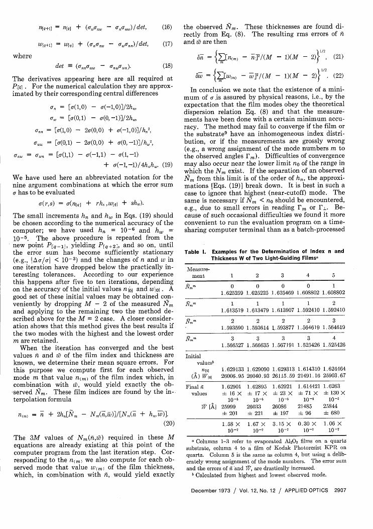
Table I. Examples for the Determination of Index n andThickness W of Two Light-Guiding Filmsa
Measure-ment 1 2 3 4 5
Nm 0 0 0 0 1
1.625259 1.625225 1.625469 1.608802 1.608802
Nmm 1 1 1 1 2
1.613519 1.613479 1.613907 1.592410 1.592410
Emm 2 2 2 2 3
1.593590 1.593614 1.593877 1.564619 1.564619
Sham 3 3 3 3 4
1.566527 1.566635 1.567191 1.525426 1.525426
Initialvaluesb
n[o] 1.629133 1.629090 1.629313 1.614310 1.624464(A) W[o] 26006.95 26040.93 26115.59 21491.16 25903.67
Final 1.62901 1.62895 1.62921 1.614421 1.6263values i 16 X i 17 X ±L 23 X i 71 X 4t 130 X
10-5 10-5 10-5 10-5 10-5
W [A] 25999 26033 26086 21485 25844+t 201 ± 221 i 197 i 96 i 680
1.58 X 1.67 X 3.15 X 0.30 X 1.06 X10-7 10-7 10-7 10-7 10-7
a Columns 1-3 refer to evaporated A1203 films on a quartzsubstrate, column 4 to a film of Kodak Photoresist KPR onquartz. Column 5 is the same as column 4, but using a delib-erately wrong assignment of the mode numbers. The error sumand the errors of i and TV, are drastically increased.
b Calculated from highest and lowest observed mode.
December 1973 / Vol. 12, No. 12 / APPLIED OPTICS 2907
where

job. In the latter case, the programmer must pro-vide for all these eventualities in advance.
The method described here can easily be extendedto the case of birefringent films in which one axis ofthe index ellipsoid is normal to the film. With suchfilms, one evaluates first the Nm obtained for TEpropagation along the two principal axes in theplane of the film. This yields two of the three prin-cipal indices of refraction. From these and the TMmeasurements, the third principal index is found,using a generalized form' 0 of Eqs. (8) and (9).
VI. ExamplesAn early example, although without details, was
contained in Ref. 2. A few more examples are inTable I. Measurements 1 to 3 concern an A12 03 filmdeposited by e-gun evaporation onto a quartz sub-strate of index no = 1.45707. This film was mea-sured at the He-Ne laser wavelength with an SF 13prism ( = 63.0129°, np = 1.73519) and showed fourTE modes. The film was measured three times atthe same spot. Different, but all weak, couplingpressures were used in these measurements. Mea-surement 3 was taken after removing the film fromthe prism and readjusting the arrangement from thebeginning. Each angle am was obtained by averag-ing four readings. By comparing columns 1 to 3, wesee that within the measured tolerances of the re-sulting index and film thickness we have the sameresults from all three measurements. This demon-strates that under weak coupling conditions thepressure changes do not influence the results.
In the other example (4 in Table I) we measured afilm of Kodak KPR2 Photoresist on quartz. 7 Theresulting mean errors are smaller because this filmhas much less scattering losses, so that the settingfor optimum coupling could be observed with higherprecision.
In order to demonstrate the self-consistency of themethod, we have repeated in column 5 the coupling
.angles of column 4, but we have deliberately used awrong assignment of the mode numbers m to theseangles. As a result, the errors of both and areseen to increase drastically.
Except for this last case, the error limits in Table Ido not exceed much the errors that were expected forthis method by theoretical considerations. Thecomputation time for the evaluation of each mea-surement (four modes) was approximately 8 sec on aCDC 3200 computer.
Appendix: Inversion of the Dispersion FormulaThe dispersion formula [Eq. (8)] cannot be solved
analytically to give Nm(n,w). For use in a computerprogram, however, the inversion may be performedin a subroutine by a simple trial and error procedure.We utilize the fact that the function
w,,,(N) = (n - N)-112xI1JN)
is strictly monotonic, wm/aN > 0, and that we mayrestrict the discussion to the finite interval no N <
n of the argument N. We calculate Wm(N1/2) at thecenter point N 112 of this interval and compare theresult with that thickness w for which we want tofind Nm(n,w). If Wm(N1/2) = w, the unknown is Nm= N1 2 . If Wm(N1/2) > w, the unknown Nm must liein the right half of that interval, N112 < Nm < n,otherwise in the left half. That half in which Nm islocated is sectioned at its center and so on, until Nmis enclosed into a sufficiently small interval N <1Nm < N+. We used here an interval of width (N+-N4 < 10N - (n - no). For a narrower interval,roundoff errors may become significant. In a finalstep, then, wm is determined by linear interpolation.between Wm(N+) and Wm(N-).
We thank R. Kersten for a critical reading of themanuscript and a stimulating discussion about thenumerical precision required for the computations.
The work on which this paper is based was partlysupported by the Bundesminister fr Forschung undTechnologie as part of the technical program of thisMinistry. The authors are exclusively responsiblefor the contents of this paper.Note Added in Proof: It is not clear, however, wheth-er there is only a simple minimum of a (n,w). Rather,indications exist that the a (n, w) surface may haveseveral relative minima. It then depends on theparticular initial values n 1 and w chosen, intowhich the minima iteration will converge. In thisway, slightly different values ft and iD may resultfrom the same set of measurements. The only guideto the reliability of a final solution n and iD is thesmallness of the error sum a, for which the valuesgiven in Table I are representative.
Another difficulty also is inherent in this method,which uses only the local topology of the a- (n,w) sur-face. In the beginning of the iteration, the steps inthe nwI plane are large, and, depending on the globaltopology of the a- (n,w) surface, it may happen thatthe error sum a- at Pq+l calculated from Eqs. (16)and (17) is larger than at Plql. In such cases one canstill obtain convergence by using not the full correc-tion terms of Eqs. (16) and (17) but only a fraction ofthem. The fraction is made so small (e.g., Y2, Y4, '8,... ) until a-q+i < IqI (damped iteration). Fromthe new point on, one may proceed as before.References1. P. K. Tien, Appl. Opt. 10, 2395 (1971).2. P. K. Tien, R. Ulrich, and R. J. Martin, Appl. Phys. Lett. 14,
291 (1969).3. J. H. Harris, R. Shubert, and J. N. Polky, J. Opt. Soc. Am.
60, 1007 (1970).4. P. K. Tien and R. Ulrich, J. Opt. Soc. Am. 60, 1325 (1970).5. R. Ulrich, J. Opt. Soc. Am. 60, 1337 (1970).6. P. K. Tien, G. Smolinsky, and R. J. Martin, Appl. Opt. 11,
1313 (1972).7. R. Ulrich and H. P. Weber, Appl. Opt. 11, 428 (1972).8. R. Ulrich, J. Opt. Soc. Am. 61, 1467 (1971).9. F. Zernike, E. L. Sloan, J. C. Webster, R. B. McGraw, and
W. L. Knecht, Topical Meeting on Integrated Optics, GuidedWaves, Materials, and Devices, Paper TuA9, Las Vegas, Ne-vada (February 1972).
10. M. Tacke and R. Ulrich, Opt. Commun. 6,234 (1973).
2908 APPLIED OPTICS / Vol. 12, No. 12 / December 1973