measurement of spatial coherence of light propagating … · measurement of spatial coherence of...
TRANSCRIPT
RADIOENGINEERING, VOL. 22, NO. 1, APRIL 2013 341
Measurement of Spatial Coherence of LightPropagating in a Turbulent Atmosphere
Peter BARCIK, Lucie HUDCOVA
Dept. of Radio Electronics, Brno University of Technology, CZ-61200 Brno, Czech Republic
[email protected], [email protected]
Abstract. A lot of issues have to be taken into account whendesigning a reliable free space optical communication link.Among these are e.g., beam wander, fluctuation of opticalintensity and loss of spatial coherence that are caused byatmospheric turbulence. This paper presents experimentalmeasurements of spatial coherence of a laser beam. Theexperimental setup is based on Young’s double pinhole ex-periment. Fringe patterns under atmospheric turbulence forfour different pinhole separations are presented. From thesefringe patterns, visibility is determined and the coherenceradius is estimated.
KeywordsAtmospheric turbulence, spatial coherence, Young’sexperiment, fringe pattern, coherence radius.
1. IntroductionFree space optical links use optical carriers with one or
several wavelength channels for transmitting data. The opti-cal power is focused into one or several optical beams. Themain advantages of free space optical links are a license-free band, electromagnetic compatibility and a high datarate [1]. The quality of these networks is highly dependenton weather conditions because the atmosphere is a transmis-sion medium. The study of effects associated with propaga-tion of light through this medium is a widely solved task inmany researches [2] - [5]; some of them are focused on mea-suring spatial coherence [6] - [8]. In this paper we presentthe measurement of spatial coherence of a laser beam by us-ing Young’s double pinhole interferometer under differentdegrees of turbulence.
2. Atmospheric Transmission MediumThe three phenomena that affect laser beam propaga-
tion through the atmosphere are scattering, absorption andatmospheric turbulence [9]. A laser beam can quickly losea part of its energy and, moreover, this loss can lead to beamquality degradation. Signal power is randomly modulated
and phase front is distorted [10]. Atmospheric turbulenceis one of the most significant phenomena in atmospherictransmission medium. Temperature differences between theearth’s surface and the atmosphere with wind variations cre-ate local unstable air masses which are broken up into turbu-lent eddies. The size of these eddies varies from millimetersto hundreds of meters. The characteristics of the fluctuationsmay be expressed by a structure function of refractive indexDn(r)
Dn(r1,r2) = 〈[n(r1)−n(r2)]2〉 (1)
where n(r1) is refractive index at point r1 and n(r2) is re-fractive index at point r2. Sharp brackets denote an ensem-ble average. For homogeneous and isotropic turbulences thedependency on distance r can be written as
Dn(r) =C2nr2/3, l0� r� L0 (2)
andDn(r) =C2
n l−4/30 r2, r� l0 (3)
where l0 is inner scale (millimeters) and L0 is outer scale(hundreds of meters) of turbulences [9].
The refractive index structure parameter C2n constitutes
a measure of the turbulence. Typically, the values of C2n
range from 10−16 m−2/3 for weak turbulence to 10−12 m−2/3
for strong turbulence.
Atmospheric turbulence leads to irradiance fluctua-tions, beam spreading and loss of spatial coherence of a laserbeam [9].
3. Spatial CoherenceAs known, a laser is a source of light with high tempo-
ral and spatial coherence. Spatial coherence is the correla-tion of the electric fields at two different positions (r1, r2) onthe same wave front. Temporal coherence is the correlationbetween the fields at two different times (t1, t2 = t1 + τ) inthe same wave train. The mutual coherence function Γ com-bines both spatial and temporal characteristics in one singleterm. It is defined as
Γ(r1,r2,τ) = 〈U(r1, t + τ)U∗(r2, t)〉 (4)
342 P. BARCIK, L. HUDCOVA, MEASUREMENT OF SPATIAL COHERENCE OF LIGHT PROPAGATING ...
where U(r1, t) is the complex electric field at position r1 andtime t, τ is time delay [11].
The principle of Young’s double slit experiment isshown in Fig. 1. Two pinholes are illuminated by a laserbeam. Intensities I1 and I2 from the pinholes P1 and P2 inter-fere at the point P at the plane π.
P1(r1)
P2(r2)
P(r )
0C
I(r,τ)
c. τ
π
Fig. 1. Young’s double slit experimental arrangement.
The normalized mutual coherence function γ12 is givenwith relation (5) and is called the complex degree of coher-ence [11]
γ12 =Γ(r1,r2,τ))√
I1I2. (5)
Intensity distribution at π plane is described by (6)
I = I1 + I2 +2√
I1I2γ12(τ)cos(ϕ12(τ)) (6)
where ϕ12 is the phase. Visibility V of the interference pat-tern can be defined by the formula [12]
V =Imax− Imin
Imax + Imin(7)
where Imax is the maximum value and Imin is the minimalvalue of the optical intensity I at the π plane. If the maximaland the minimal value of the optical intensity from relation(6) is deduced and these values are put into equation (7) weobtain
V =2√
I1I2γ12(τ)
I1 + I2. (8)
An expression for the complex degree of coherence γ12 (9)comes out from relationship (8),
γ12(τ) =V (I1 + I2)
2√
I1I2. (9)
From (9) is clear that if the intensity I1 and I2 are equal, thenthe absolute value of γ12 is identical to the visibility V of thefringe caused by the interference of two wave fronts [11].The value of γ12 indicates the degree of the laser beam coher-ence for a given spectral linewidth, pinhole separation andthe state of the atmosphere. Loss of spatial coherence canbe deduced from a complex degree of coherence. Visibility
of interference fringe is reduced with increasing degree ofatmospheric turbulences and separation of pinholes. Loss ofspatial coherence limits the effective aperture size of hetero-dyne detection optical receivers [9].
The coherence radius is useful for determining the sizeof the receiver aperture through a process called aperture av-eraging and also for determining the separation distance ofdetectors in a multiple receiver system [13]. The coherenceradius is defined as separation distance at which the modulusof the complex degree of coherence falls to 1/e [9]. In [14]spatial coherence radius for the infinity plane wave ρpl andspherical wave ρsp is given by
ρpl = (1.46C2nk2L)−3/5, l0� ρpl � L0, (10)
ρsp = (0.55C2nk2L)−3/5, l0� ρsp� L0 (11)
where k is the wave number and L is the distance between theoptical transmitter and receiver. The meaning of parametersl0 and L0 is mentioned in the previous section. For a colli-mated Gaussian-beam wave, the spatial coherence radius ρgis approximated by [14]
ρg = (0.55C2nk2L(a+0.62Λ
11/6))−3/5, l0� ρg� L0(12)
where the Fresnel ratio Λ is for a beam width at the receiverplane w defined by
Λ =2Lkw2 . (13)
Parameter a is defined by
a =1−Θ8/3
1−Θ, Θ≥ 0 (14)
where Θ is the refractive beam parameter and can be calcu-lated by
Θ =1[
1+(
2Lkw2
0
)2] (15)
where w0 is beam width at the waist.
4. Experimental MeasurementIn [15] it has been shown that the loss of coher-
ence in a turbulent atmosphere can be experimentally deter-mined by measuring spatial interference in a modified Mach-Zender interferometer. We chose a simpler method based onYoung’s pinhole experiment.
For the experimental measurement we used a He-Nelaser with a wavelength of 632.8 nm. The beam width atthe waist was w0 = 0.28 mm and at the receiver plane it wasw = 1.06 mm. Two heaters with an effective diameter of185 mm were used for generating a turbulent atmosphere.The laser beam passed 100 mm above the heaters. For eachtemperature level the relative variance of optical power σ2
P
RADIOENGINEERING, VOL. 22, NO. 1, APRIL 2013 343
was measured and the relative variance of optical intensityσ2
I was calculated. The ratio of the relative variance of op-tical power and the relative variance of optical intensity isgiven by [5]
σ2P
σ2I=
(1+1.062
kD2
4L
)−7/8
. (16)
This ratio is determined by the diameter of the receivingaperture D = 0.2 mm, the link distance L = 1.9 m and thewave number k. From the calculated value of relative opticalintensity variance σ2
I we estimated the C2n parameter accord-
ing to Rytov variance [9]
σ2I = 1.23C2
nk7/6L11/6. (17)
The beam passed through two pinholes with a diameter of0.5 mm each. The pinhole separation d was set to 0.5 mm,1 mm, 1.5 mm and 2 mm. The beam was locked exactly be-tween the two pinholes in the vertical and horizontal plane.At the receiver plane we obtained a fringe pattern causedby the interference. Optical intensity was scanned with theCCD camera SP620U Ophir Spiricon. The distance betweenthe laser source and the camera was set to 1.9 m.
Gaussianbeam
Laser
Double pinhole
0.56 m0.85 m
CCDcamera d
1.2 m1.9 m
Thermal heaters
Fig. 2. Experimental setup for spatial coherence measurement.
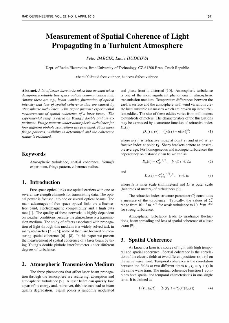
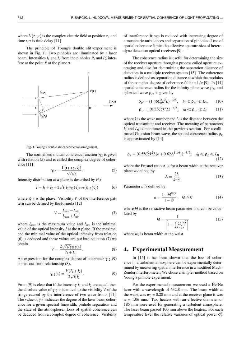
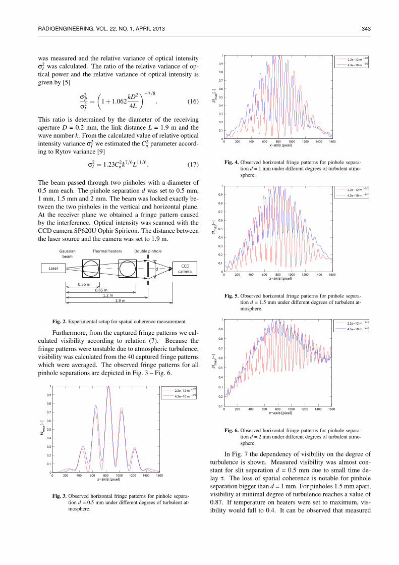
Furthermore, from the captured fringe patterns we cal-culated visibility according to relation (7). Because thefringe patterns were unstable due to atmospheric turbulence,visibility was calculated from the 40 captured fringe patternswhich were averaged. The observed fringe patterns for allpinhole separations are depicted in Fig. 3 – Fig. 6.
0 200 400 600 800 1000 1200 1400 16000
0.1
0.2
0.3
0.4
0.5
0.6
0.7
0.8
0.9
1
x−axis [pixel]
I/I m
ax [−
]
2.2e−12 m −2/3
4.3e−10 m −2/3
0 200 400 600 800 1000 1200 1400 16000.1
0.2
0.3
0.4
0.5
0.6
0.7
0.8
0.9
1
x−axis [pixel]
I/I m
ax [−
]
0 200 400 600 800 1000 1200 1400 16000
0.1
0.2
0.3
0.4
0.5
0.6
0.7
0.8
0.9
1
x−axis [pixel]
I/I m
ax [−
]
0 200 400 600 800 1000 1200 1400 16000
0.1
0.2
0.3
0.4
0.5
0.6
0.7
0.8
0.9
1
x−axis [pixel]
I/I m
ax [−
]
Fig. 3. Observed horizontal fringe patterns for pinhole separa-tion d = 0.5 mm under different degrees of turbulent at-mosphere.
0 200 400 600 800 1000 1200 1400 16000
0.1
0.2
0.3
0.4
0.5
0.6
0.7
0.8
0.9
1
x−axis [pixel]
I/I m
ax [−
]
2.2e−12 m −2/3
4.3e−10 m −2/3
0 200 400 600 800 1000 1200 1400 16000.1
0.2
0.3
0.4
0.5
0.6
0.7
0.8
0.9
1
x−axis [pixel]
I/I m
ax [−
]
0 200 400 600 800 1000 1200 1400 16000
0.1
0.2
0.3
0.4
0.5
0.6
0.7
0.8
0.9
1
x−axis [pixel]
I/I m
ax [−
]
Fig. 4. Observed horizontal fringe patterns for pinhole separa-tion d = 1 mm under different degrees of turbulent atmo-sphere.
0 200 400 600 800 1000 1200 1400 16000
0.1
0.2
0.3
0.4
0.5
0.6
0.7
0.8
0.9
1
x−axis [pixel]
I/I m
ax [−
]
2.2e−12 m −2/3
4.3e−10 m −2/3
0 200 400 600 800 1000 1200 1400 16000.1
0.2
0.3
0.4
0.5
0.6
0.7
0.8
0.9
1
x−axis [pixel]
I/I m
ax [−
]
0 200 400 600 800 1000 1200 1400 16000
0.1
0.2
0.3
0.4
0.5
0.6
0.7
0.8
0.9
1
x−axis [pixel]
I/I m
ax [−
]
22.3 °C60.0 °C
Fig. 5. Observed horizontal fringe patterns for pinhole separa-tion d = 1.5 mm under different degrees of turbulent at-mosphere.
0 200 400 600 800 1000 1200 1400 16000
0.1
0.2
0.3
0.4
0.5
0.6
0.7
0.8
0.9
1
x−axis [pixel]
I/I m
ax [−
]
2.2e−12 m −2/3
4.3e−10 m −2/3
0 200 400 600 800 1000 1200 1400 16000.1
0.2
0.3
0.4
0.5
0.6
0.7
0.8
0.9
1
x−axis [pixel]
I/I m
ax [−
]
Fig. 6. Observed horizontal fringe patterns for pinhole separa-tion d = 2 mm under different degrees of turbulent atmo-sphere.
In Fig. 7 the dependency of visibility on the degree ofturbulence is shown. Measured visibility was almost con-stant for slit separation d = 0.5 mm due to small time de-lay τ. The loss of spatial coherence is notable for pinholeseparation bigger than d = 1 mm. For pinholes 1.5 mm apart,visibility at minimal degree of turbulence reaches a value of0.87. If temperature on heaters were set to maximum, vis-ibility would fall to 0.4. It can be observed that measured
344 P. BARCIK, L. HUDCOVA, MEASUREMENT OF SPATIAL COHERENCE OF LIGHT PROPAGATING ...
optical power in the interference fringes for slit separationd = 2 mm was so small (relative to beam halfwidth) thatmeasurement of the visibility was on the limit of sensitivityof the CCD camera.
10−12 10−11 10−10 10−90.1
0.2
0.3
0.4
0.5
0.6
0.7
0.8
0.9
1
Cn2 [m−2/3]
V [−
]
0.5 mm1 mm1.5 mm2 mm
Fig. 7. Dependency of interference fringe visibility on refractiveindex structure parameter.
Dependency of fringe pattern visibility on pinhole sep-aration is shown in Fig. 8. From this figure we estimatedcoherence radius ρ0 at the receiver plane.
0 200 400 600 800 1000 1200 1400 16000
0.1
0.2
0.3
0.4
0.5
0.6
0.7
0.8
0.9
1
x−axis [pixel]
I/I m
ax [−
]
2.2e−12 m −2/3
4.3e−10 m −2/3
0.5 1 1.5 20.1
0.2
0.3
0.4
0.5
0.6
0.7
0.8
0.9
1
d [mm]
V [−
]
2.2e−12 m −2/3
2.8e−12 m −2/3
9.5e−12 m −2/3
6.2e−11 m −2/3
8.1e−11 m −2/3
3.0e−10 m −2/3
4.3e−10 m −2/3
0.5 1 1.5 20.1
0.2
0.3
0.4
0.5
0.6
0.7
0.8
0.9
1
d [mm]
V [−
]
22.3 °C30.4 °C32.8 °C36.2 °C44.0 °C52.0 °C60.0 °C
d [mm]
V [-]
Fig. 8. Dependency of interference fringe visibility on slit sepa-ration.
The coherence radii for different refractive index struc-ture parameters are listed in Tab. 1.
Structure Coherenceparameter radiusC2
n [m−2/3] ρ0 [mm]
2.20.10−12 2.002.80.10−12 1.879.54.10−12 1.886.19.10−11 1.818.07.10−11 1.803.04.10−10 1.654.31.10−10 1.57
Tab. 1. Coherence radius for different degrees of turbulence.
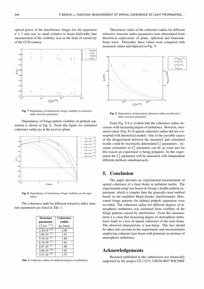
Theoretical values of the coherence radius for differentrefractive structure index parameters were determined fromtheoretical expressions of plane, spherical and Gaussian-beam wave. Thereafter, these values were compared withmeasured values and depicted in Fig. 9.
10−11 10−100
10
20
30
ρ 0 [mm
] Cn
2 [m−2/3 ]10−11 10−10
1.4
1.6
1.8
2
ρ meas
ured
[mm
]
l0<<ρgauss<<L0
l0<<ρpl<<L0
l0<<ρsp<<L0
ρmeasured
Fig. 9. Dependency of theoretical coherence radius on refractiveindex structure parameter.
From Fig. 9 it is evident that the coherence radius de-creases with increasing degree of turbulence. However, mea-sured values (Fig. 9) of spatial coherence radius did not cor-respond with theoretical models. One of the possible causesof the disagreement between the measured and calculatedresults could be incorrectly determined C2
n parameters. Ac-curate estimation of C2
n parameter can be an issue and forthis reason an experiment is being prepared. In this exper-iment the C2
n parameter will be measured with independentdifferent methods simultaneously.
5. ConclusionThe paper presents an experimental measurement of
spatial coherence of a laser beam in turbulent media. Theexperimental setup was based on Young’s double pinhole ex-periment, which is simpler than the generally used methodbased on the modified Mach-Zender interferometer. Hori-zontal fringe patterns for defined pinhole separation wererecorded. The coherence radius for different degrees of at-mospheric turbulence was estimated from visibility of thefringe patterns caused by interference. From this measure-ment it is clear that increasing degree of atmospheric turbu-lence leads to a loss of spatial coherence of the laser beam.The observed characteristic is non-linear. This fact shouldbe taken into account in the experiments and measurementsemploying coherent laser beam with potential occurrence ofatmospheric turbulence.
AcknowledgementsResearch published in this submission was financially
supported by the project CZ.1.07/2.3.00/20.0007 WICOMT
RADIOENGINEERING, VOL. 22, NO. 1, APRIL 2013 345
of the operational program Education for competitiveness.
The described research was performed in laborato-ries supported by the SIX project; the registration numberCZ.1.05/2.1.00/03.0072, the operational program Researchand Development for Innovation.
Research described in the paper was also financiallysupported by the COST project LD12067 OPTAPRO, by theCzech Grant Agency under grant No GAP102/11/1376, bythe Czech Ministry of Industry and Trade under grant agree-ment No. FR-TI2/705 and Specific research project FEKT-S-11-13.
References
[1] MUHAMMAD, S. S., PLANK, T., LEITGEB, E., FRIEDL, A.,ZETTL, K., JAVORNIK, T., SCHMITT, N. Challenges in estab-lishing free space optical communications between flying vehicles.In 6th International Symposium on Commmunications Systems, Net-works and Digital Signal Processing (CNSDSP). Graz (Austria),2008, p. 82 - 86.
[2] WALTHER, F. G., MOORES, J. D., MURPHY, R. J., MICHAEL,S., NOWAK, G. A. A process for free-space laser communicationssystem design. Free-Space Laser Communications IX; Proceedingsof SPIE, 2009, vol. 74640V, doi:10.1117/12.826256.
[3] HAMMEL, S., MCBRYDE, K., REINHARDT, C. Measurementand modeling of beam wander. Atmospheric Optics IV: Turbu-lence and Propagation; Proceedings of SPIE, 2011, vol. 81610F,doi:10.1117/12.896597.
[4] CHEN JING, AI YOUNG Laser signal intensity and aperture averag-ing analysis in 16 km free-space optical links. In Symposium on Pho-tonics and Optoelectronic (SOPO). Chengdu (China), 2010, p. 1 - 4,doi: 10.1109/SOPO.2010.5504015.
[5] KHALIGHI, M. A., SCHWARTZ, N., AITAMER, N., BOUREN-NAME, S. Fading reduction by aperture averaging and spatial di-versity in optical wireless systems. Journal of Optical Communi-cations and Networking, 2009, vol. 1, no. 6, p. 580 - 593, doi:10.1364/JOCN.1.000580.
[6] REDDING, B., CHOMA, M. A., CAO, H. Spatial coherence of ran-dom laser emission. Optics letters, 2011. vol. 36, no. 17, p. 3404 -3406.
[7] LUNDEBERG, L. D. A., LOUSBERG, G. P., BOIKO, D. L.,KAPON, E. Spatial coherence measurements in arrays of coupledvertical cavity surface emitting lasers. Applied Physics Letters, 2007,vol. 90, no. 2, p. 021103 - 021103-3, doi: 10.1063/1.2431474.
[8] REDDING, B., CHOMA, M. A., CAO, H. Spatially incoherent ran-dom lasers for full field optical coherence tomography. ConferenceLasers and Electro-Optics (CLEO). Baltimore (USA), 2011.
[9] ANDREWS, L. C., PHILLIPS, R. L. Laser Beam Propagationthrough Random Media. Washington (USA): SPIE Press, 2005.
[10] SHAIK, K. S. Atmospheric propagation effects relevant to opticalcommunication. TDA Progress Report 42-94, 1988, p. 180 - 200.
[11] HLUBINA, P. Temporal coherence and mode structure of the He-Nelaser beam spectrum. Optoelectronics Review, 1996, vol. 4, no. 3/4,p. 117 - 122.
[12] MANDEL, L., WOLF, E. Optical Coherence and Quantum Optics.Cambridge University Press, 1995.
[13] POPOOLA, W. O. Subcarrier Intensity Modulated Free-Space Opti-cal Communication Systems. Ph.D. thesis. Newcastle (UK): Univer-sity of Northumbria, 2009.
[14] ANDREWS, L. C. Field Guide to Atmospheric Optics. Washington(USA): SPIE Press, 2004.
[15] WANG, S., YANG, S. H., WU, X., ZHAO, C. M., ZHU, Q. H. Exper-imental study on influence of atmospheric turbulence on coherenceof dual-frequency laser. Chinese Physics Letters, 2010, vol. 27, no. 8.
About Authors. . .
Peter BARCIK was born in 1988. Currently he is a studentat the Department of Radio Electronics, Brno University ofTechnology. His Master’s thesis is focused on measurementof relative variance of optical intensity in laser beams.
Lucie HUDCOVA was born in 1981. She graduated fromthe Brno University of Technology in 2006; in 2010 she re-ceived a PhD degree in Electronics and Communications atthe same university. Currently she is an assistant professorat the Department of Radio Electronics, Brno University ofTechnology. Her specialization is optoelectronics, opticalcommunications and free space optics.