measurement of permeability using a bench-top centrifuge
TRANSCRIPT
Anderson, C. et al. Geotechnique [http://dx.doi.org/10.1680/geot.13.P.112]
1
Measurement of permeability using a bench-top centrifuge
C. ANDERSON�, V. SIVAKUMAR† and J. A. BLACK‡
The commonly used British Standard constant head triaxial permeability test for testing of fine-grained soils is relatively time consuming. A reduction in the required time for soil permeabilitytesting would provide potential cost savings to the construction industry, particularly in the construc-tion quality assurance of landfill clay liners. The purpose of this paper is to evaluate an alternativeapproach of measuring permeability of fine-grained soils benefiting from accelerated time scaling forseepage flow when testing specimens in elevated gravity conditions provided by a centrifuge. As partof the investigation, an apparatus was designed and produced to measure water flow through soilsamples under conditions of elevated gravitational acceleration using a small desktop laboratorycentrifuge. A membrane was used to hydrostatically confine the test sample. A miniature dataacquisition system was designed and incorporated in the apparatus to monitor and record changes inhead and flow throughout the tests. Under enhanced gravity in the centrifuge, the flow through thesample was under ‘variable head’ conditions as opposed to ‘constant head’ conditions as in the classicconstant head permeability tests conducted at 1g. A mathematical model was developed for analysisof Darcy’s coefficient of permeability under conditions of elevated gravitational acceleration andverified using the results obtained. The test data compare well with the results on analogous samplesobtained using the classical British Standard constant head permeability tests.
KEYWORDS: centrifuge modelling; clays; groundwater; landfills; permeability
INTRODUCTIONLow-permeability soil barriers are often used in geotechnicalworks for controlling leakage flow and contaminant migra-tion. There are several methods of measuring the permeabilityof soils including: the British Standard (BS) flexible boundaryconstant head permeability (BS 1377, Part 6:1990, BSI(1990)); the accelerated permeability (AP) test (EnvironmentAgency, 2003); the ramped accelerated permeability (RAP)test; and several in-situ measurement techniques (Olsen et al.,1985; Aiban & Znidarcic, 1989; Huang et al., 1998a, 1998b).In the case of landfill applications, as part of constructionquality control (CQA) to ensure that liner materials havesufficiently low permeability, tests are carried out on undis-turbed samples recovered from the site or representativesamples produced in the laboratory. Within the UK, regula-tions specify that permeability should be measured in accor-dance with BS 1377: Part 6:1990 (BSI, 1990), method 6. TheBS test is a relatively time-consuming procedure with turn-around time up to 2 months from time of sampling to reportof results. It is shown (by two of the present authors andcolleagues in a paper that is under review) that the APmethod does not yield any significant improvement in thetime saving, while the permeability values obtained using APare up to ten times lower than those derived using the BS test.The purpose of this paper is to investigate the use of alaboratory-based centrifuge to measure the permeability offine materials and to examine whether the results are compar-able with measurements obtained using the BS procedure.
Centrifuge modelling has been long recognised as a toolwhich, by elevation of the force of gravity, can achievesimilarity of stresses between small-scale models and full-
scale prototypes under in-situ conditions (Schofield, 1980;Garnier et al., 2007). Centrifuges are normally used tomodel prototype situations to provide an independent evalua-tion of performance for many geotechnical problems, forexample, mining (Bucky, 1931), retaining structures (Bolton& Powrie, 1988), embankments (Take & Bolton, 2011) andoffshore foundations White (2008). They can also be used tomeasure material characteristics such as the diffusion coeffi-cient, retardation factor and the coefficient of permeability.A centrifuge accelerates water flow in porous soils andtherefore it can reduce the time for testing low-permeabilitysoils compared to conventional procedures. Some centrifugeset-ups can also accommodate up to six samples, allowingmultiple tests to be run simultaneously (Mitchell, 1998).
Mitchell (1993, 1994a, 1994b, 1998) and Theriault &Mitchell (1997) carried out permeability tests using a smallcentrifuge and, in their testing procedure, the flow of per-meant into and out of the sample was measured once thecentrifuge had stopped. Singh & Gupta (2000, 2001) adopteda procedure in which the flow was measured in-flight byobserving the permeant level through a small window on a0.63 m rotor centrifuge using a stroboscope. In their studiesthe outflow head was maintained constant. Singh & Gupta(2001, 2002) demonstrated the reliability of permeabilityvalues obtained using this set-up when compared with stan-dard procedures (i.e. the BS test). The present paper presentsexperimental observations and interpretation of data forcalculating the coefficient of permeability of fine soils inwhich an in-flight automated system is used to measure theinflow and outflow of water through the soil in a bench-toplaboratory centrifuge. The term ‘permeability’ is interchange-able with ‘coefficient of permeability’ or ‘Darcy’s permeabil-ity’. The latter term is generally used throughout the paper.
USE OF SCALING FACTORS TO DEFINE DARCY’SCOEFFICIENT OF PERMEABILITY
The scaling effect is significant in the research reportedhere; therefore, a brief summary of this aspect is discussed
Manuscript received 4 July 2013; revised manuscript accepted 2December 2014.Discussion on this paper is welcomed by the editor.� Byrne Looby Partners, Belfast, UK.† Queen’s University Belfast, Belfast, UK.‡ University of Sheffield, Sheffield, UK.
herein. As with all disciplines in which physical models areused, in geotechnical centrifuge modelling and testing thereis a tendency to use scaling factors appropriate to themodels and prototypes under investigation. Muir-Wood(2004) states that, provided the height of the model is lessthan approximately 0.1 times the radius of rotation, thevariation of the acceleration field along the sample isgenerally considered marginal and can be assumed constant.However, if the length of the sample is more than 0.1 timesthe radius of rotation then the acceleration along the samplelength, and therefore the acceleration ratio N (ratio betweenthe acceleration in the centrifuge at a given point and theearth’s gravity g), is variable and thus should not be con-sidered constant. This situation generally prevails in smallgeotechnical laboratory centrifuges (Black, 2014).
In order to formulate an appropriate analysis for centri-fuge permeability testing, consideration must first be givento the scaling laws applied to seepage flow. From theliterature (Garnier et al., 2007) relating to the scaling lawsfor centrifuge modelling it is well established that seepagevelocity, v, is scaled directly by the factor N, where
vm ¼ Nvp (1)
where vm is the model seepage velocity and vp is theseepage velocity in prototype. This scaling relationship hasbeen verified by a number of authors studying both steady-state and transient seepage flow in centrifuge modelling(Cargill & Ko, 1983; Arulanandan et al., 1988; Khalifa etal., 2000; Singh & Gupta, 2000). There is, however, con-troversy within the literature regarding whether it is thepermeability, k, or the hydraulic gradient, i, that is a functionof N. This controversy has been raised by various authorsincluding Goodings (1979, 1985), Butterfield (2000), Dean(2001) and Madabhushi & Thusyanthan (2003). However, itis commonly overlooked as the seepage velocity is generallythe value under investigation, and irrespective of whether kor i is the scaled parameter, the end result, vm ¼ Nvp,remains the same. This method may be satisfactory where itis appropriate to consider N as a constant throughout thedepth of a model; however, if there is a requirement for theconsideration of N as a variable related to radius of rotation(as in the present investigation discussed later), then a morethorough understanding of the parameters to be scaled isnecessary.
Cargill & Ko (1983), Tan & Scott (1985), Mitchell (1998)and Singh & Gupta (2000) defined the hydraulic gradient ias independent of gravity and considered permeability k tobe directly proportional to gravity with a resultant scalingfactor of N. The formal definition of hydraulic gradient, aspresented in the majority of the literature, is the ratio ofchange in total head, ˜h, and the length, L, over which thatchange in head occurs. When scaling of dimensions of acentrifuge model both L and ˜h will be N times smaller inthe model, and as a result the hydraulic gradient can beargued to be the same in the model and prototype (i.e.im ¼ ip).
The parameter known as the intrinsic permeability k,derived by Muskat (1937), is shown in equation (2) relatedto Darcy’s coefficient of permeability k by the followingexpression
k ¼ kª
�¼ k
rg
�(2)
where ª, � and r are the unit weight, dynamic viscosity andthe density of the fluid, respectively. This shows that becauseDarcy’s coefficient of permeability is directly proportional tothe unit weight of the permeant ª then under conditions ofelevated gravity k will increase N times (i.e. km ¼ Nkp) on
the assumption that the dynamic viscosity is unaffected bygravity.
Alternatively, Schofield (1980), Goodings (1985) and Tay-lor (1987) have all suggested permeability to be independentof gravity and that the hydraulic gradient has the scalingfactor of N. Taylor (1987) highlights an inconsistency withregard to the relationship shown in equation (2), due to thedirect relationship between permeability and gravity equation(2) suggests that any given soil mass in space at zero gravityis impermeable. However, this is not the case, as a soil masshas a given amount of pore space irrespective of gravityand, if a fluid with an applied pressure gradient is presentacross the boundary of that soil mass, then permeant flowwill take place. Goodings (1985) suggests that Darcy’s coef-ficient of permeability, k, should not be scaled and shouldbe considered as a material constant.
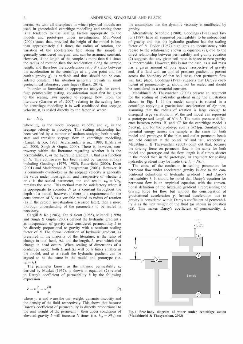
Madabhushi & Thusyanthan (2003) present an argumentfor the scaling of hydraulic gradient using the illustrationshown in Fig. 1. If the model sample is rotated in acentrifuge applying a gravitational acceleration of Ng then,assuming that the radius of rotation is large enough todisregard large variations in N, the soil model can representa prototype soil length of N 3 L. The static pressure differ-ence between points ‘B’ and ‘C’ for the centrifuge model isLr(Ng), and for the prototype soil is (NL)rg: Similarly, thepotential energy across the sample is the same for bothmodel and prototype if the inlet and outlet permeant headsare held constant at the points ‘A’ and ‘D’, respectively.Madabhushi & Thusyanthan (2003) point out that, becausethe driving force on permeant flow is the same for bothmodel and prototype and the flow length is N times shorterin the model than in the prototype, an argument for scalinghydraulic gradient may be made (i.e. ip ¼ Nim).
The cause of the confusion in scaling parameters forpermeant flow under accelerated gravity is due to the con-ventional definitions of hydraulic gradient i and Darcy’spermeability k. It should be noted that Darcy’s equation forpermeant flow is an empirical equation, with the conven-tional definition of the hydraulic gradient i representing thedriving force for flow, but without the consideration ofgravitational acceleration g. Instead acceleration due togravity is considered within Darcy’s coefficient of permeabil-ity k as the unit weight of the fluid (as shown in equation(2)). This makes Darcy’s coefficient of permeability, k,
Δh
A
B
C
LSample
D
Fig. 1. Free-body diagram of water under centrifuge action(Madabhushi & Thusyanthan, 2003)
2 ANDERSON, SIVAKUMAR AND BLACK

directly proportional to gravity, and relevant under conditionsof normal gravitational acceleration (i.e. N ¼ 1). For thisreason, and giving consideration to the variability of gravita-tional acceleration experienced within a small centrifuge, itis erroneous to use a scaling relationship, to define a valuefor k, when using a small centrifuge permeameter. Instead,Madabhushi & Thusyanthan (2003) suggest that for centri-fuge modelling (or assessing permeant flow in a centrifuge),gravity should be represented by the energy gradient (poten-tial energy gradient + pressure energy gradient) which drivesthe permeant flow.
From Bernoulli’s principle, the energy required for per-meation is the energy associated with the movement of thepermeant (velocity head), plus the energy from the pressurein the permeant (pressure head), plus the energy from theheight of the fluid relative to an arbitrary datum (elevationhead); such that
˜h ¼ ˜v2
2g
!þ ˜u
rg
� �þ ˜z (3)
where u, v and z are pore-water pressure, velocity of thewater flow and elevation above datum, respectively. Lambe& Whitman (1979) state that, for fluid flow through soils,velocity head is too small to be of any consequence andmay therefore be neglected. With consideration of equations(2) and (3), seepage velocity may be represented by thefollowing relationship
v ¼ krg
�3
[(˜u=rg)þ ˜z]
L(4)
where ˜u and ˜z are the change in permeant pressure andthe change in elevation over a distance L, parallel to thedirection of fluid flow across the permeated medium, respec-tively. Rearranging equation (4), an expression which relatesthe energy gradient per unit volume of fluid as the drivingforce for flow (i.e. energy difference) may be derived. Un-like hydraulic gradient the energy is directly proportional togravitational acceleration
v ¼ k�
3˜(uþ zgr)
L(5)
As the intrinsic permeability relationship derived byMuskat (1937) is regarded as valid under conditions ofnormal gravity then
k1g ¼ kª1g
�(6)
A relationship between Darcy’s coefficient of permeabilityand the energy gradient per unit volume of fluid may thenbe defined as
v ¼ k1g
ª1g
3˜(uþ zgr)
L(7)
where k1g and ª1g are Darcy’s coefficient of permeability at1g and the unit weight of the permeant at 1g, respectively.The use of equation (7) allows the interpretation of thecoefficient of permeability under conditions of elevatedgravitational acceleration and is fundamental to the accurateanalysis of centrifuge permeability tests.
EXPERIMENTAL PROGRAMME AND ANALYTICALMODELGeneral arrangement and overview
The investigations were carried out using a Sigma 235bench-top centrifuge which has a 0.20 m rotor and four0.75l containers to locate the proposed permeameter set-up.The specific design requirements were
(a) the sample size should be small enough to be accom-modated within the centrifuge cups of the centrifuge
(b) the device should be lightweight and it should includechambers to hold reservoirs of sufficient quantities ofpermeant for the inflow and outflow volume
(c) it should provide automated measurement of permeantinflow and outflow and an estimation of the hydraulicgradient/pressure differential applied across the sampleduring testing (i.e. in-flight data recovery)
(d ) flexible lateral boundary conditions should be achieved(e) there should be automated opening of the inlet valve only
when sufficient lateral pressures are applied to thesample, to negate preferential flow between the samplesides and the flexible lateral boundary.
Figure 2 shows the general arrangement of the prototypeapparatus, which can accommodate cylindrical soil samples75 mm in diameter and 30 mm long. The sample is axiallyconfined between the bottom and top caps (which includeporous stones) and laterally confined by a 75 mm diameterrubber membrane. A drainage line is provided in the bottomcap to facilitate the inflow of permeant using a flexibledrainage line connected by way of a spring gravity valvefrom the inlet chamber. A similar arrangement is providedfor the outflow from the top of the sample to the outletchamber. The inlet and outlet chambers consist of twoconcentric cylinders, permanently connected to a circularbase. These chambers are suspended above the sample by ahanging bracket supported by the top of the centrifuge cup.In order to provide a flow through the sample, the inletchamber is filled with permeant to a higher level than thatin the outlet chamber, thereby producing a pore-water pres-sure differential gradient across the sample. Under elevatedgravity, this gradient increases, producing an increased flowof permeant from the inlet chamber upwards through thesample, and into the outlet chamber. As such, the flowcondition applied during the test is essentially a fallinghead/rising tail condition. Ignoring the effects of head lossthrough the system, the flow would continue until thepermeant levels in the chambers equalise.
Miniature pressure transducers incorporated into the baseof both inlet and outlet chambers facilitate the measurementof pressure head generated from the volume of water retainedin each chamber under elevated gravity during centrifugetesting. Using the pressure obtained from each pressure cell,and knowing the rotational speed of the centrifuge, a mathe-matical model derived for this device (discussed later) allowscalculation of changes in inlet and outlet volumes duringtesting, and calculation of water pressures applied to thesample base and the top of the sample. As a result, pressurechanges monitored by the miniature pressure cells may bedirectly correlated to the permeability of the sample. Bothpressure transducers are connected to a data logger (by wayof plug-in sockets, Fig. 3), which is secured to the top of thepermeant chambers, after permeant levels within the innerand outer chamber have been filled as necessary during set-up. The centrifuge permeameter is set to take readings atspecific intervals during the test using a programmablemicroprocessor.
A membrane was used to hydrostatically confine the testsample. As previously detailed, during centrifuge tests, verti-cal stress on the sample will increase due to the increasing
MEASUREMENT OF PERMEABILITY USING A BENCH-TOP CENTRIFUGE 3

acceleration, both from its own self-weight and the appliedload from any mass resting on top of the sample. This in turncould lead to lateral straining, and in extreme cases, shearingof the sample, which may affect the permeant flow andtherefore yield unrepresentative permeability results. In orderto minimise loading of the sample, the inlet and outletchambers and data-logging component are suspended usingthe hanging bracket shown in Fig. 2 and the permeant lineconnections between the chambers and the sample are highlyflexible. In order to ensure minimal lateral straining of thesample during centrifuge, the vertical stresses imposed by thetop cap and the sample self-weight are balanced using lateralconfining pressures surrounding the flexible membranearound the sample. This confining pressure is generated usinga high-density liquid (HDL), corresponding to the bulkdensity of the soil sample, positioned inside the centrifugecup laterally surrounding the sample, top cap and bottomcap. As the material used for the production of the top capshas a higher density than the sample or HDL, to allowequalisation of vertical and horizontal pressures at the sampletop, the top cap was designed with elongated walled sides toallow an appropriate increased head of HDL to be used.
Under flexible boundary conditions, a requirement toensure no preferential flow between the membrane and thesample sides is a minimum effective confining pressure of15 kPa (Mitchell, 1994b). The maximum permeant pressureapplied to the sample is defined by the permeant head in theinlet chamber at the start of the test. As the confiningpressure generated by the HDL increases laterally from thetop to the base of the sample, to account for the requiredeffective confining pressures and minimise the divergence ineffective pressure across the sample length, the inlet flow isapplied to the base of the sample. Hence an upward flow is
generated through the sample during testing. The gravity-control valve was used to prevent permeant flow from theinlet chamber until the rotational speed in the centrifuge wassufficient to generate an effective confining pressure of15 kPa to negate preferential flow.
The electronic component associated with the centrifugepermeameter is relatively simple in design and operation.The reliability of the data logger under elevated accelerationwas examined in previous research (Brown et al., 2009).The data logger consists of off-the-shelf components, withthe exception of the printed circuit board (PCB), which wasdesigned and manufactured at the Queen’s University Belfast(QUB) workshop. The major restriction for the selection ofelectrical components was their size, given the relativelysmall space in which the data-logging component was to behoused (Fig. 2).
The electronic data logger is pictured in Fig. 3. The twopressure cells are connected to separate amplifiers, whichamplify the voltage output from the pressure cells. Theamplified signal from both load cells is fed into an analogue-to-digital converter (ADC). This digital signal is then fed toa microprocessor, known as a ‘Basic’ stamp. It is essentiallyan extremely small printed circuit board, which contains theessential elements of a microprocessor system, including: amicrocontroller containing the central processing unit (CPU),a built-in read-only memory (ROM) containing the Basic(i.e. programming language) interpreter. In addition to thestorage of data, the stamp performs a number of other roles,and essentially controls the workings of the data-loggingunit. Two 3.6 V lithium-ion batteries supply a 7.2 V powersupply directly to the stamp. the stamp contains a regulator,and therefore redistributes a regulated 5 V power supply tothe remaining circuit (i.e. the two load cells, two amplifiers
(a) (b)
Membrane
Permeametersupport base
Centrifuge cup lid
Data logger
Inlet chamber
Outlet chamber
Hanging bracket
Centrifuge cup
Gravity spring valve(at a reduced scale)
Top cap extension
Inlet and outletpressure cells
O-ring
O-ring
Top cap includingporous disk
Bottom cap includingporous disk
High-density liquid
SampleDiameter: 75 mm
Height: 30 mm
Inlet pressure line
Outlet pressure line
Electronic cable
Note: To provide clarity within this schematic some components of theapparatus have been omitted, including details of the fixtures and fittings,the permeameter base support and the confining membrane. All detailedcomponents are drawn to scale with the exception of the gravity spring valve,which has been reduced to allow clarification of flow paths.
Fig. 2. Centrifuge permeability system: (a) schematic diagram; (b) photograph
4 ANDERSON, SIVAKUMAR AND BLACK

and the ADC). It was found that continuous power supply tothese other components led to a greatly shortened batterylife, which was incompatible with the required test duration.In order to address this, the software written for the stampwas modified to control the power supply to these additionalcomponents, which are now ‘powered up’ and ‘powereddown’ immediately before and after a reading is taken. Eachpressure cell was routinely calibrated using a desk-top pres-sure calibrator, both periodically and after any adjustmentwas made to the circuit. Brown et al. (2009) confirmed thatthe calibration factor was not affected by acceleration up to600g.
In order to check the above-mentioned calibration, theapparatus (excluding the sample, caps and HDL) was testedin the centrifuge, both periodically and after any adjustmentwas made to the circuit. Known quantities of water, meas-ured to the nearest 0.01 cm3, were placed in both the inletand outlet chambers and the centrifuge was run at variousaccelerated gravities. The bases of both chambers weresealed and therefore there was no flow through the inlet oroutlet tubing. Fig. 4 shows the raw data obtained from thecalibration test. The key details the amount of water in the
chamber for each plot, while the g values presented correlateto the N value applied in the centrifuge.
Mathematical modelThe analysis is based on an Excel spreadsheet, which
allows the user to input testing variables and visualise theresultant stresses imposed on the sample, taking into accountthe variation in the gravitational acceleration with distancefrom the point of rotation. The set-up of this model is basedon a segmented approach, where the weights of the solidcomponents and the pressures of the liquids (i.e. the per-meant and HDL) are calculated over small integral distancesalong the axis of the permeameter, pertaining to the rota-tional speed of the centrifuge. The input variables forcalculating the stress distributions are detailed in Table 1.
The output values allow a visual assessment of the stressconditions applied to the sample, and graphical outputs takethe following forms
(a)
(b)
Fig. 3. (a) Water reservoir for inlet and outlet; (b) data logger
1g100g
800
1000
1200
1400
1600
1800
2000
2200
2400
0 10 20 30 40 50 60 70 80 90 100
Raw
da
ta: b
its
Time: min
6 cm in chamber3 12 in chambercm3
18 in chambercm3 24 in chambercm3
100g 150g 150g200g1g 200g250g 250g300g
Fig. 4. Pressure cell output plotted against time (and the influenceof gravitational acceleration)
Table 1. Input variables for calculating stresses
Variable description Units Label inFig. 5
Rotational speed of centrifuge r/min øLength of sample mm LInlet chamber permeant level mm yi
Outlet chamber permeant level mm yo
Radius to bottom of sample mm rb
Radius to bottom of chamber mm RDensity of the HDL g/cm3 –HDL level (distance below the top of the top cap) mm –Soil bulk density g/cm3 –Density of the permeant g/cm3 –
Details of top cap:
Diameter of top cap mm –Total length of top cap mm –Thickness of top cap extension wall mm –Length of top cap extension wall mm –Thickness of porous disc mm –Diameter of porous disc mm –Density of top cap material (stainless steel) g/cm3 –Density of porous stone g/cm3 –
MEASUREMENT OF PERMEABILITY USING A BENCH-TOP CENTRIFUGE 5

(a) a comparative assessment of vertical stress in the sample(imposed by the top cap weight and sample weight) andhorizontal stress in the sample (imposed by the pressureof the HDL) along the length of the sample
(b) effective confining pressure across the sample (lateralpressure created by the HDL minus the estimated porewater pressure ascertained from permeant pressures/levels at the inlet (bottom) and outlet (top)).
A trial-and-error approach allows the user to ascertain theappropriate testing variables to use during test set-up toensure that (a) the sample does not experience large differ-ences in applied lateral and axial stresses; and (b) effectiveconfining pressures are sufficient (given the setting of thegravity spring valve) to negate preferential flow conditions.
As previously detailed, interpretation of permeability val-ues from the results of a centrifuge analysis, neglecting thechanges in gravitational acceleration with distance from thepoint of rotation, can lead to errors in the output values. Assuch, the energy gradient method of calculating permeabilityflow (shown in equation (7)), taking into account the chang-ing acceleration with distance from the axis of rotation, hasbeen derived and input into a spreadsheet to ascertaindirectly the results gained from the centrifuge permeameterdesigned as part of this research investigation. A derivationis given below based on the methodology proposed byMadabhushi & Thusyanthan (2003), and the reader shouldmake reference to Fig. 5 for the symbols used in the derivedequations.
As previously discussed, a relationship between Darcy’scoefficient of permeability and energy gradient per unitvolume of fluid may be defined as shown in equation (7).
v ¼ k1g
ª1g
3˜(uþ zgr)
L(7)
In order to establish an expression for pressure, u, con-sideration must be given to the effects of radius on thegravity. At any point below the water table at radius r fromthe point of rotation, water pressure may be defined as
u(r) ¼ðrø2rdr ¼ rø2r2
2þ C1 (8)
where r is the density of the permeant used, ø is theangular velocity of the centrifuge and C1 is a constant ofintegration established by considering the boundary condi-tion of zero pressure at the water table established frompermeant level, y, inside the inlet or outlet chambers. Fig. 5shows that at the water table the radius, r, equates to R � y(where R is the radius to bottom of inlet and outletchambers), therefore
C1 ¼ �rø2
2(R� y)2 (9)
Substitution of equation (9) into equation (8) establishesan expression for pore-water pressure at any point along the
ω
R
rb
yo
y1
Datum
R
Inlet chamberOutlet chamber
Hanging bracket
Centrifuge cup
Bottom cap includingporous disc
Soil sample
Bottom cap includingporous disc
Fig. 5. Centrifuge parameters
6 ANDERSON, SIVAKUMAR AND BLACK

permeameter at radius, r, dependent upon the permeant levely inside the inlet or outlet chamber.
u(r) ¼ �ø2
2[r2 � (R� y)2] (10)
At the base of the sample r ¼ rb and y ¼ yi, therefore
ubot ¼�ø2
2[r2
b � (R� yi)2] (11)
Similarly, at the top of the sample r ¼ rb � L and y ¼ yo,therefore
utop ¼rø2
2[(rb � L)2 � (R� yo)2] (12)
Because of the linear change in gravitational acceleration,it is not correct to assume that the elevation head componentat the top of the sample is simply equal to the length of thesample L (i.e. the distance from the datum). Instead anexpression representing potential energy P at any distance dfrom the datum is required. As such, the potential energymay be defined as
P(d) ¼ zrg ¼ðrø2(rb � d)dd
¼ rø2 rbd � d2
2
� �þ C2
(13)
where C2 is a constant of integration found by consideringthe boundary condition d ¼ 0 when P ¼ 0. Therefore C2 ¼ 0and
P(d) ¼ rø2 rbd � d2
2
� �(14)
At the top of the sample d ¼ L and at the bottom of thesample d ¼ 0, therefore
Ptop ¼ rø2 rbL� L2
2
� �(15)
and
Pbot ¼ 0 (16)
From equations (7), (11) and (12), the energy gradient perunit volume of flow may be expressed as
˜(uþ zrg)
L¼
˜(ubot � (utop þ zrgtop))
L
¼
ø2˜rw
2[r2
b � (R� yi)2]
�
� rw
2[(rb � L)2 � (R� yo)2]
� rw rbL� L2
2
� ��L
(17)
Considering equations (7) and (17), an expression fordetermining permeability using the centrifuge permeabilitysystem designed as part of this research may be defined as
k1g ¼˜Qª1g
At3
L
ø2˜rw
2[r2
b � (R� yi)2]
�
� rw
2[(rb � L)2 � (R� yo)2]
� rw rbL� L2
2
� ��
(18)
where k1g is Darcy’s coefficient of permeability of thesample at normal gravitational acceleration, Q is the dis-charge in a specified time t (i.e. the time between permeantlevel readings in the inlet and outlet chambers, yi and yo
respectively), A is the cross-sectional area of the sample, ª1g
is the unit weight of the permeant under normal gravitationalacceleration, ø is the rotational speed of the centrifuge, L isthe length of the sample, rw is the density of the permeant,rb is the radial distance between point of rotation and thebottom of the sample, and R is the radial distance to thebase of the inlet and outlet chambers. The relevant units foreach of the parameters are listed in Table 2.
As discussed earlier, the values of permeant level in theinlet chamber yi and outlet chamber yo can be accuratelycorrelated with data from the pressure cells. Knowing thecross-sectional area of both the inlet chamber ai and outletchamber ao it is possible to calculate the flow into and outof the sample between readings, that is for a given timeinterval set by the software controlling the electronics com-ponent. Equation (18) can then be used, together with theappropriate calibration factors for the test cell, to determinethe coefficient of permeability.
RESULTS AND DISCUSSION OF CENTRIFUGEPERMEABILITY TESTING
The above formulations allowed the assessment of pore-water pressure, vertical pressure and horizontal pressuredistributions on the sample during centrifuge testing, alongwith the parameters listed in Table 2. Fig. 6(a) shows thepore-water pressure variation in the inlet tube (through
Table 2. Centrifuge parameters
Variable Notation Magnitude Unit
Radius to bottom of sample rb 198.5 mmRadius to bottom of inlet and chambers R 103 mmLength of sample L 30 mmCross-sectional area of inlet chamber ai 803.84 mm2
Cross-sectional area of outlet chamber ao 828.96 mm2
Cross-sectional area of sample A 4415 mm2
Time between readings dt 120 minRotational speed of centrifuge ø 914 rev/minDensity of permeant rw 1 g/cm3
MEASUREMENT OF PERMEABILITY USING A BENCH-TOP CENTRIFUGE 7

the base of a 30 mm high sample), along the length of thesample and in the outlet tube connecting to the outletchamber. The pore-water pressure was about 38 kPa at thebase of the sample and 24 kPa at the top of the sample
under gravitation of 250g while the inlet chamber was filledwith water to its highest level, the outlet being nearly empty.The total, effective vertical and horizontal pressure distribu-tions are shown in Figs 6(b) and 6(c), respectively. Theeffective lateral pressure is about 38 kPa and it is sufficientto prevent any preferential flow. Analysis was also carriedout to predict the inflow/outflow pattern for a given per-meability of 7.1 3 10�11 m/s at an elevated gravitationalacceleration equivalent to 250g. The predicted inflow/outflowpatterns using equation (18) are shown in Figure 7, whichshows the falling head in the inlet chamber and rising headin the outlet chamber and the required time for stabilisa-tions.
The new device may be used to measure permeability offine soil; however, its application to highly permeable soilssuch as sand is limited. For example, for a sample with arelatively high coefficient of permeability of 1 3 10�6 m/s,the majority of the flow would take place in approximately1 min at 100g. This time frame would allow insufficient dataacquisition to accurately determine the coefficient of per-meability. However, giving consideration to the typical rangeof coefficient of permeability values attained for a fine-grained sample, say 5 3 10�8 m/s to 5 3 10�11 m/s, themajority of the flow would take place within approximately38 min at 100g and 7.5 days at 350g, respectively. Theseestimates are for the given sample dimensions used in thepresent research. These estimates indicate that the devicedeveloped as part of this research is suitable to measure thepermeability of clay liners, where the desired permeabilityvalues are typically less than 1.0 3 10�9 m/s (HMG, 2003).
Over the course of the research period, numerous per-meability tests were carried out to assess the functionality ofthe centrifuge permeameter and make adjustments whererequired. Four permeability tests were carried out using thecentrifuge permeameter at an acceleration of 250g, onreconstituted samples of kaolin clay, and compared with theresults from the BS test.
Two sample types were produced by consolidating kaolinslurry of 90% water content to pressures of 250 kPa and500 kPa for a period of 72 h, in a one-dimensional consoli-dation chamber, to produce samples 150 mm high by100 mm in diameter. In total, three sub-samples (one for BStests and two for the centrifuge permeameter tests) wereprepared from the consolidated kaolin, using a sample cutter
0
5
10
15
20
25
30
35
0 50 100 150
Dis
tanc
e fr
om s
ampl
e ba
se: m
m
Pressure: kN/m(b)
2
Sam
ple
Total verticalpressure
Effective verticalpressure
0
5
10
15
20
25
30
35
0 50 100 150
Dis
tanc
e fr
om s
ampl
e ba
se: m
m
Pressure: kN/m(c)
2
Sam
ple
Total horizontalpressure
Effective horizontalpressure
0
5
10
15
20
25
30
35
0 10 20 30 40 50
Dis
tanc
e fr
om s
ampl
e ba
se: m
m
Pressure: kN/m(a)
2
PWP profile inlet tubeS
ampl
e
PWP profileoutlet tube
PWP profile alongthe sample
Fig. 6. (a) Pore water, (b) vertical and (c) horizontal pressuresacting on the sample
0
5
10
15
20
25
30
0 2000 4000 6000 8000 10000 12000
Inlet chamber
Vol
ume
ofw
ate
r: c
m3
Time: min
Outlet chamber
Fig. 7. Predicted inflow and outflow under 250g in centrifuge
8 ANDERSON, SIVAKUMAR AND BLACK

of 75 mm internal diameter, and trimmed to a height of30 mm. The two BS tests were carried out using a standardpermeability cell, following the procedure described in BS1377: part 6:1990 (BSI, 1990), method 6. The confiningpressure, the inlet and outlet pressures were 75, 33 and25 kPa, yielding an effective pressure of 41 kPa with ahydraulic gradient of 26.7, producing an upward flowthrough the sample. These pressures correspond to averageconfining pressure, inlet pressure and outlet pressure that thesample experienced in the centrifuge. These BS tests lastedapproximately 5 days.
Typical observations in relation to the flow of water fromthe inlet chamber to outlet chamber in the centrifuge per-meameter testing are shown in Fig. 8. Fig. 8(a) shows theinflow/outflow pattern for a sample previously consolidatedto 500 kPa and the pattern for a sample consolidated to250 kPa is shown in Fig. 8(b). The volumes of water in theinflow and outflow chambers were approaching similar valuesin about 3 days in the case of the sample consolidated to500 kPa and just over 0.5 days for the sample previouslyconsolidated to 250 kPa, although longer time may be neededto achieve complete equalisation of volume of water in the
inlet and outlet chambers. In both cases the acceleration wasmaintained at 250g. The coefficient of permeability wascalculated using equation (18) on an incremental basis. Sincethe samples were previously consolidated to higher pressurethan the pressures applied in the centrifuge (Fig. 6), someelastic swelling was expected, contributing to the differencebetween the volume of water that flowed into the sample andthat collected in the outlet chamber. Once the sample hasresponded to the stress regime in the centrifuge, the voidratio should remain unchanged and therefore the permeabil-ity should be unaffected, except where any an influence dueto the change in hydraulic gradient as the head of the inflowis reducing and that for the out flow is increasing. The flowthrough the sample will stop when the permeant levels in theinflow and outflow chambers equalise. Testing indicates that,compared with the BS tests, a significant saving in testduration, on the order of 1.5–4-fold can be achieved usingthe centrifuge permeameter. The calculated permeabilityvalues using the BS test and the centrifuge permeameter testsare listed in Table 3. The permeability results from the twotests show good correlation, with factors of divergence intest method on analogous samples ranging from 1.01 to1.13. The results indicate repeatability in the values derivedfrom the centrifuge permeameter apparatus.
As a result, based on these tests it is suggested that thecentrifuge permeameter, and its method of analysis, produceacceptable and repeatable results on samples of reconstitutedfine-grained material. However, it should be noted that theresults obtained from the centrifuge permeameter are limitedin number to date; therefore, the conclusions made regardingits abilities need to be rigorously scrutinised by further testingbefore firm conclusions may be drawn on its viability as analternative short-duration method of permeability testing forwider application, that is, when testing compacted clayswhich are initially unsaturated. It is expected that sampleswhich are not fully saturated may pose a problem, in terms ofvolume of water available in the reservoir to flush the air outof the sample and saturate it. It is possible with the presentsystem for the test to be halted and, if required, the reservoirscan be re-filled; alternatively, a more advanced centrifugefacility could be developed that incorporates a hydraulicrotary union to enable in-flight delivery of fluid.
CONCLUSIONSAn apparatus was designed and produced to measure
water flow through soil specimens under elevated gravity ina small desk-top laboratory centrifuge. The lateral boundaryconditions were flexible and tests were carried out using thefalling head test method. An inbuilt data acquisition systemallowed monitoring of inlet and outlet flow during centrifugeaction. The data collected were analysed using a mathema-tical model, which is presented in the paper. The followingconclusions are drawn.
0
5
10
15
20
25
30
35
0 1000 2000 3000 4000
Inlet chamber
Vol
ume
ofw
ate
r: c
m3
Outlet chamber
Time: min(a)
0
5
10
15
20
25
30
35
40
45
0 200 400 600 800 1000Time: min
(b)
Vol
ume
ofw
ate
r: c
m3
Inlet chamber
Outlet chamber
Fig. 8. Measured inflow–outflow under acceleration of 250g:(a) consolidation pressure 500 kPa; (b) consolidation pressure250 kPa
Table 3. Calculated permeability using BS and centrifuge per-meameter
Initial consolidationpressure: kPa
Test type Initial voidratio
Calculatedpermeability: m/s
250 CP� 1.425 4.32 3 10�10
250 CP 1.432 4.44 3 10�10
250 BS 1.423 4.63 3 10�10
500 CP 1.361 9.80 3 10�11
500 CP 1.365 1.12 3 10�10
500 BS 1.361 9.89 3 10�11
� CP, centrifuge permeameter.
MEASUREMENT OF PERMEABILITY USING A BENCH-TOP CENTRIFUGE 9

(a) The calculated permeability of reconstituted kaolin,consolidated to different pressures using the centrifugepermeability device, agrees well with the permeabilityvalues calculated using the data generated from the BS test.
(b) The duration of testing in the centrifuge is relativelyshort. However, it should be noted that a completeequilibrium of water in inlet and outlet chambers mayrequire more time, although that is not essential fordetermining the permeability value.
(c) Further investigation is required to assess permeability ofcompacted soils, in which the duration of the testing canbe expected to be higher due to the unsaturated nature ofthe soil at the start of testing.
ACKNOWLEDGEMENTSThe authors would like to thank Mr Kenny McDonald
(chief technician, electronic laboratory, SPACE, Queen’sUniversity Belfast) and Mr Jim Knox (head of technicians,CNC workshop, Faculty of Engineering, Queen’s UniversityBelfast) for their input into the research.
NOTATIONA cross-sectional area of sampleai cross-sectional area of inlet chamberao cross-sectional area of outlet chamber
C1, C2 constants of integrationd given distance from datumg gravitational accelerationi hydraulic gradient
im hydraulic gradient in modelip hydraulic gradient prototypek coefficient of permeability or Darcy’s permeability
km model permeabilitykp prototype permeabilityL length of the sampleN acceleration ratioP potential energyQ rate of flowR radius to bottom of inlet and outlet chambersrb radius to bottom of samplet timeu pore-water pressurev velocity
vm model seepage velocityvp prototype seepage velocityyi initial height of water in inner chamberyo initial height of water in outer chamberz elevationª unit weight
ª1g unit weight of permeant˜h change in total head˜t time between readings˜u change in pore-water pressure˜v change in velocity˜z change elevationk intrinsic permeability� dynamic viscosityr density of water
rw density of permeantø rotational speed of centrifuge
REFERENCESAiban, S. A. & Znidarcic, D. (1989). Evaluation of the flow pump
and constant head techniques for permeability measurements.Geotechnique 39, No. 4, 655–666, http://dx.doi.org/10.1680/geot.1989.39.4.655.
Arulanandan, K., Thompson, P. Y., Kutter, B. L., Meegoda, N. J.,Muraleetharan, K. K. & Yogachandran, C. (1988). Centrifugemodeling of transport processes for pollutants in soils. J. Geo-tech. Engng 114, No. 2, 185–205.
Black, J. A. (2014). Development of a small scale teaching cen-trifuge. In ICPMG2014 – Physical modelling in geotechnics:Proceedings of the 8th international conference on physicalmodelling in geotechnics (eds C. Gaudin and D. White), pp.187–192. Boca Raton, FL, USA: CRC Press.
Bolton, M. D. & Powrie, W. (1988). Behaviour of diaphragm wallsin clay prior to collapse. Geotechnique 38, No. 2, 167–189,http://dx.doi.org/10.1680/geot.1988.38.2.167.
Brown, J. L., Sivakumar, V., McKinley, J. D., Harmon, N. & McDo-nald, K. (2009). The miniature wireless data-logger for pressuremeasurements in geotechnical applications. Geotechnique 59, No.2, 141–149, http://dx.doi.org/10.1680/geot.2007.00133.
BSI (1990). BS 1377:1990: Methods of tests for soils for civilengineering purposes, code of practice. London, UK: BSI.
Bucky, P. B. (1931). The use of models for the study of miningproblems, Technical Publication 425. New York, NY, USA:American Institute of Mining and Metallurgical Engineers.
Butterfield, R. (2000). Scale-modelling of fluid flow in geotechnicalcentrifuges. Soils Found. 40, No. 6, 39–45.
Cargill, K. W. & Ko, H. Y. (1983). Centrifugal modeling oftransient water flow. J. Geotech. Engng 109, No. 4, 536–555.
Dean, E. T. R. (2001). Discussion on ‘Scale-modelling of fluidflow in geotechnical centrifuges’. Soils Found. 41, No. 4, 108–110.
Environment Agency (2003). Validation of the accelerated perme-ability test for landfill engineering, R&D Technical SummaryP1-398/TS. Hatfield, UK: Environment Agency.
Garnier, J., Gaudin, C., Springman, S. M., Culligan, P. J., Goodings,D. J., Konig, D., Kutter, B. L., Phillips, R., Randolph, M. F. &Thorel, L. (2007). Catalogue of scaling laws and similitudequestions in geotechnical centrifuge modelling. Int. J. Phys.Modelling Geotech. 7, No. 3, 1–23.
Goodings, D. J. (1979). Centrifugal modelling of soil structures.Part I. Centrifugal modelling of slope failures. PhD thesis,University of Cambridge, UK.
Goodings, D. J. (1985). Relationships for modelling water effects ingeotechnical centrifuge models. In Application of centrifugemodelling to geotechnical design: Proceedings of a symposiumon the application of centrifuge modelling to geotechnical de-sign, Manchester, 16–18 April 1984 (ed. W. Craig). Rotterdam,the Netherlands: Balkema.
HMG (Her Majesty’s Government) (2003). Environmental protec-tion. The landfill regulations (Northern Ireland), Statutory Rulesof Northern Ireland, 2003 no. 496. London, UK: The StationeryOffice.
Huang, S., Barbour, S. L. & Fredlund, D. G. (1998a). Developmentand verification of a coefficient of permeability function for adeformable unsaturated soil. Can. Geotech. J. 35, No. 3, 411–425.
Huang, S., Fredlund, D. G. & Barbour, S. L. (1998b). Measurementof the coefficient of permeability for a deformable unsaturatedsoil using a triaxial permeameter. Can. Geotech. J. 35, No. 3,426–432.
Khalifa, A., Garnier, J., Thomas, P. & Rault, G. (2000). Scalinglaws of water flow in centrifuge models. In Proceedings of theinternational symposium on physical modelling and testing inenvironmental geotechnics, La Baule, France (eds J. Garnier,L. Thorel and E. Haza), pp. 207–216. Paris, France: LaboratoireCentral des Ponts et Chaussees.
Lambe, T. W. & Whitman, R. V. (1979). Soil mechanics (SIversion). New York, NY, USA: Wiley.
Madabhushi, S. P. G. & Thusyanthan, N. I. (2003). Scaling ofseepage flow velocity in centrifuge models. Cambridge, UK:Cambridge University Press.
Mitchell, J. K. (1993). Fundamentals of soil behaviour, 2nd edn.New York, NY, USA: Wiley.
Mitchell, R. J. (1994a). Centrifuge techniques for testing clay linersamples. Can. Geotech. J. 31, No. 4, 577–582.
Mitchell, R. J. (1994b). Flexible, no lateral strain apparatus for clayliner-leachate testing. In Centrifuge ’94: Proceedings of the1994 international conference, Singapore (eds F. H. Lee, C. F.Leung and T. S. Tan), pp. 351–351. Boca Raton, FL, USA:CRC Press.
Mitchell, R. J. (1998). The eleventh annual R. M. Hardy keynoteaddress, 1997: Centrifuge in geoenvironmental practice and edu-cation. Can. Geotech. J. 35, No. 4, 630–640.
10 ANDERSON, SIVAKUMAR AND BLACK

Muir-Wood, D. (2004). Geotechnical modelling. London, UK: Spon.Muskat, M. (1937). The flow of fluids through porous media.
J. Appl. Phys. 8, No. 4, 274–282.Olsen, H. W., Nichols, R. W. & Rice, T. L. (1985). Low gradient
permeability measurements in a triaxial system. Geotechnique35, No. 2, 145–157, http://dx.doi.org/10.1680/geot.1985.35.2.145.
Schofield, A. N. (1980). Cambridge geotechnical centrifuge opera-tions. Geotechnique 30, No. 3, 227–268, http://dx.doi.org/10.1680/geot.1980.30.3.227.
Singh, D. N. & Gupta, A. K. (2000). Modelling hydraulic con-ductivity in a small centrifuge. Can. Geotech. J.37, No. 5,1150–1155.
Singh, D. N. & Gupta, A. K. (2001). Falling head hydraulicconductivity tests in a geotechnical centrifuge. J. Testing andEvaluation 29, No. 3, 258–263.
Singh, D. N. & Gupta, A. K. (2002). Modelling hydraulic con-
ductivity in a small centrifuge: Reply. Can. Geotech. J. 39, No.2, 488–489.
Take, W. A. & Bolton, M. D. (2011). Seasonal ratcheting andsoftening in clay slopes, leading to first-time failure. Geotechni-que 61, No. 9, 757–769, http://dx.doi.org/10.1680/geot.9.P.125.
Tan, T. S. & Scott, R. F. (1985). Centrifuge scaling considerationsfor fluid-particle systems. Geotechnique 35, No. 4, 461–470,http://dx.doi.org/10.1680/geot.1985.35.4.461.
Taylor, R. N. (1987). Discussion on Tan & Scott (1985). Geotechnique37, No. 1, 131–133, http://dx.doi.org/10.1680/geot.1987.37.1.131.
Theriault, J. A. & Mitchell, R. J. (1997). Use of a modellingcentrifuge for testing clay liner compatibility with permeants.Can. Geotech. J. 34, No. 1, 71–77.
White, D. J. (2008). Contributions to Geotechnique 1948–2008:Physical modelling. Geotechnique 58, No. 5, 413–421, http://dx.doi.org/10.1680/geot.2008.58.5.413.
MEASUREMENT OF PERMEABILITY USING A BENCH-TOP CENTRIFUGE 11