measurement of h2o in catalytic reformer hydrogen … of h 2o in catalytic reformer hydrogen recycle...
TRANSCRIPT

Measurement of H2O in Catalytic Reformer Hydrogen Recycle Streams Using Tunable Diode Laser Absorption Spectroscopy (TDLAS)
by W. Gary Engelhart, Product Line Marketing Manager, SpectraSensors, Inc.
IntroductionThe Catalytic Reformer Unit in modern refineries converts naphtha into high-octane aromatic compounds termed reformates used in gasoline blending and formulation, and hydrogen as a by-product. Universal Oil Products (UOP) developed the catalytic reforming process and brought the first unit into operation in 19491.
There are three types of catalytic reforming units categorized by the type of catalyst regeneration procedure they employ; cyclic, semi-regenerative, and continuous. Semi-regenerative reformers (SRR) are the type in most widespread service in refineries, representing 60% of worldwide capacity2. Continuous catalytic reformers (CCR) account for 28% of worldwide capacity2.
Catalytic ReformingAn SRR typically has three fixed bed catalytic reactors (Figure 1) employing a bimetallic platinum/rhenium catalyst on a chloride alumina support (Pt/Re/Al2O3-Cl). Bimetallic Pt/Re catalyst for naphtha reforming was introduced and patented by Chevron in 19673.
In operation, naphtha and hydrogen gas are mixed, preheated and passed through the reactors. The metallic catalyst components catalyze hydrogenation and dehydrogenation reactions. Dehydrogenation is a major chemical reaction in catalytic reforming yielding large quantities of hydrogen which is recycled to support other reactions and minimize coke deposition on the catalyst2. Water along with a chloride compound is continuously injected to chlorinate the alumina and maintain acid sites needed to perform hydrocracking, isomerization and cyclization conversion reactions. All these reforming reactions occur in series and concurrently with dehydrogenation and isomerization favored in the first reactor and dehydrogenation, isomerization, hydrocracking, and cyclization in the second and third reactors.

2
AX
Net Hydrogen
HydrogenRecycle Gas
Off Gas
Liquid
Reformate
Recy
cle G
as
Fired Heater Fired Heater Fired Heater
Fixed Bed Reactor
Naphtha and Hydrogen
Recycle Gas
Feed (Naptha)
Cooler
Gas Separator
Fixed Bed Reactor
Fixed Bed Reactor
Figure 1. Semi-Regenerative Catalytic Reformer – (SRR)
The hot reaction products exiting the third reactor are passed through a heat exchanger to a gas separator. Hydrogen from the separator is directed to the hydrogen recycle compressor to feed the reforming process. The liquid phase in the separator is transferred to a fractionation column termed a stabilizer. The liquid bottoms in the stabilizer are high-octane reformate destined for gasoline blending. The overhead off gas from the stabilizer is sent to the refinery’s gas processing unit to recover an LPG mix of propane and butane.
A CCR (Figure 2) typically has a 3-stage stacked reactor and a separate, external catalyst regenerator. Gravity causes the catalyst to flow down through the reactor stack. A portion of partially-deactivated catalyst is continuously extracted from the bottom of the reactor stack and transferred to the regenerator. Inside the regenerator, coke deposits on the catalyst are burned off and the catalyst is oxy-chlorinated and dried sequentially in separate zones. Following reactivation with hydrogen the catalyst is returned to the top reactor in the CCR stack. Catalyst reduction takes place in a reduction zone above the first reactor4. This process regenerates the catalyst within a CCR approximately every three days1.
AX
Heater
Fuel Gas
Light endsto recovery
LowPressure
Separator
Recycle HydrogenReformate
Net Liquid
Net H2 Gas
Stabilizertower
Regeneratedcatalyst
Stacked Reactor
Spent Catalyst
CCR Regenerator
Feed
Figure 2. Continuous Catalytic Reformer – (CCR)
In a CCR the reformer and regeneration sections operate independently so the reformer is not exposed to the harsh regeneration conditions and corrosion issues encountered in an SRR. CCR units operate continuously for a period of 3 to 6 years without a shutdown for catalyst replacement. UOP has stated that; “Commercial CCR Platforming units routinely achieve on-stream efficiencies of more than 97%”5.

3
An SRR must be completely shut down periodically for catalyst regeneration, halting production of reformate and hydrogen gas used in other refinery operations. Depending upon the capacity of the refinery and its slate of products the financial loss from shutdown of an SRR can easily exceed $1 million per day.
H2O Measurement in the H2 Recycle Stream of Catalytic ReformersAccurate measurement and control of moisture is a technical challenge in the operation of catalytic reformer units. During normal operation the moisture content of the reactor feed is controlled at a low level (5 – 50 ppm). Refineries try to avoid excessive moisture levels as Bill Deutschlander, an analyzer engineer with Eichleay in Concord, California noted; “You don’t want too much moisture on the catalyst, if you get too much moisture it strips the chloride from the catalyst which reduces the catalyst cracking/isomerization activity. Then adding more chloride to make up for this loss also results in more problems downstream, i.e. acid attack and corrosion.”
Corrosion mechanisms and locations in CCR and SRR units are described in API 571: Damage Mechanisms Affecting Fixed Equipment in the Refining Industry⁶. Section 5.1.1.4.4 identifies specific units and equipment affected by HCl corrosion stating the following for catalytic reforming units;
“(1) Chlorides may be stripped from the catalyst and react to form HCl that carries through the effluent train, regeneration system, stabilizer tower, debutanizer tower and feed/preheat exchangers. (2) HCl containing vapors can migrate through the gas plant fractionation section resulting in mix point or acid dew point corrosion.”
Some of the problems arising from elevated H2O levels in catalytic reformer units are summarized in Table 1.
Table 1. Problems Arising from Elevated H2O Levels in Refinery Catalytic Reformer Units
Problem Consequence
H2O strips chloride from acid sites on surface of alumina catalyst
Reduced catalyst efficiency and yield of reformate compounds, formation and transport of HCl throughout process piping and equipment
HCl reacts with NH3 forming ammonium chloride (NH4Cl) salt
NH4Cl precipitates and forms deposits in the H2 recycle compressor requiring shutdown for cleaning / maintenance
Entrained HCl reaching debutanizer causes severe corrosion and damage
Corrosion in the debutanizer overhead system requiring shutdown for repairs and equipment replacement
H2O and HCl entrained in the hydrogen recycle stream enters the naphtha hydrotreater and desulfurizer storage tank
Corrosion damage, and excessive accumulation of highly acidic (pH < 2) water requiring increased maintenance and inspections
Formation and precipitation of ammonium chloride (NH4Cl) salt deposits is another corrosion problem encountered where high temperature streams containing NH3 and HCl are cooled. Section 5.1.1.3.3 (c) of API 571 states; “Ammonium chloride salts are hygroscopic, and readily absorb water. A small amount of water can lead to very aggressive corrosion (> 100 mpy (> 2.5 mm/y).”
Section 5.1.1.3.4 (c) states: “Reactor effluent steams and the H2 recycle system are subject to ammonium chloride salting and corrosion.”
The equipment repair and/or replacement cost, labor cost, and lost revenue from shut down of a catalytic reformer unit due to elevated H2O levels and corrosion underscore the importance of moisture measurement and control. An example of the costs incurred by a U.S. West Coast refinery to deal with corrosion damage from elevated H2O levels in their SRR are shown in Table 2.

4
Table 2. Example of Costs Associated with Corrosion Damage from Elevated H2O Levels in a U.S. West Coast Refinery Catalytic Reformer Unit
Problem Cost Impact
Shutdown of H2 recycle compressor to remove NH4Cl deposits
3-day shutdown resulting in;Loss of H2 productionLoss of reformate production(> $1 million + per day)
Shutdown to replace corroded Debutanizer overhead system components and heat exchanger fin fan tube
Loss of H2 productionLoss of reformate production(> $1 million + per day)Equipment & labor costs(> $250,000 per incident)
H2 shortage from catalytic reformer shutdown for use in other refinery hydrotreating /desulfurization processes
1-day shutdown of catalytic reformer($700,000 in lost diesel fuel production)
Catalyst activity in an SRR gradually decreases over time as coke is deposited on the catalyst and chloride is lost. The catalyst beds in an SRR are periodically regenerated to restore catalyst activity. The SRR is taken off line and regeneration is performed by in-situ oxidation once every 6 to 24 months. Regeneration involves depressurizing the reactors and purging them with nitrogen to remove hydrocarbons. Air is then introduced to perform high temperature oxidation and burn the coke deposits off the catalyst. Oxidation produces H2O which leaches chloride from the catalyst. After the oxidation step, a chlorinated organic compound is introduced to restore the chloride level necessary for catalyst activity. A hydrogen purge is then performed to reduce the catalyst metal oxides formed during coke burn-off to an active state. Hydrogen is then recirculated through the reformer unit to dry down the moisture level prior to restarting regular operation. The H2O level in the hydrogen recycle gas stream is monitored during dry down to help gauge when conditions have reached a level to support restarting the SRR unit. The total regeneration process can take up to 15 days depending on the associated maintenance required.
Monitoring moisture concentration during regeneration and subsequent drying of the catalyst upon reintroduction of the feed gas is important for optimizing catalyst performance and life. During regeneration moisture is measured at higher levels (up to 1,000 ppm) to monitor the progress of catalyst decoking. The expensive catalyst can be regenerated 3 or 4 times before it must be replaced. The spent catalyst is returned to the manufacturer to recover the platinum or rhenium metals. One of the ways to monitor H2O levels for optimal catalyst activity and during in-situ regeneration is by measuring the water content in SRR hydrogen recycle gas (Figure 1).
Problems with Traditional Moisture MeasurementsHistorically, refineries have relied on two types of moisture measurement devices, Aluminum Oxide (Al2O3) electrochemical sensors and oscillating Quartz Crystal Microbalances. While electrochemical sensors are relatively simple instruments they have a number of deficiencies when employed for measurements in harsh process gas applications such as SRR hydrogen recycle streams. The major problem with moisture analyzers using Al2O3 sensors is that the sensor element is in direct contact with the process gas and entrained contaminants. In the case of SRR hydrogen recycle streams this means the sensor element is directly exposed to HCl, H2S, HCN, and other contaminants that corrode and destroy the sensor requiring frequent replacement. To compensate for the high rate of sensor failure many refineries have installed redundant sensors as backups in case one electrochemical analyzer stops working.
The sensor element of Quartz Crystal Microbalances must also be in direct contact with the process gas to operate. Bill Deutschlander explained why this is problematic; “The Oscillating Quartz (Crystal Microbalance) is subject to corrosion
5
problems from the chlorides. The chlorides attack the sensor and cause inaccuracy. Changing out the sensor is very expensive.”
The on-stream factor or analyzer availability of electrochemical sensors and QCMs is poor due to the corrosion damage these devices sustain in normal operation. The American Petroleum Institute provides guidance on a suitable on-stream factor for analyzers in ANSI/API RP 555-20017. Section 1.3.c states; “On-stream factor: A goal of 95% or greater on-stream factor of on-line availability is generally desired. Analyzers exhibiting less than 95% are generally not considered reliable by operations and closed-loop control applications. On-stream factor is the total time the analyzer is operating reliably, relative to process operations.”
The corrosion problem encountered with Al2O3 electrochemical sensors is noted in Section 18.2.3 of ANSI/API RP 555-2001; “Disadvantages of the aluminum-oxide sensor include the following: a. The probe is susceptible to severe corrosion in the presence of certain acids or bases in streams that have a high moisture content.”
A further complication is that both types of analyzers are slow to respond to changes in moisture concentration due to extended wet-up and dry-down times. An extended dry-down time poses a particular problem for using these devices to monitor catalyst bed drying in an SRR following in-situ regeneration. The cumulative delayed response to decreasing H2O concentration results in a significantly longer (apparent) catalyst drying curve from these devices. This is a known problem with quartz crystal microbalances. Section 18.2.4 of ANSI/API RP 555-2001 states; “The disadvantages of the vibrating crystal analyzer include these: c. The cell can be poisoned by excessive water concentration in the sample.” The cumulative measurement lag time resulting from exposure to elevated levels of H2O and extended sensor dry-down time can delay the decision to restart an SRR for a day or more costing the refinery hundreds of thousands of dollars per day.
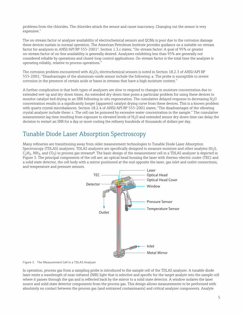
Tunable Diode Laser Absorption SpectroscopyMany refineries are transitioning away from older measurement technologies to Tunable Diode Laser Absorption Spectroscopy (TDLAS) analyzers. TDLAS analyzers are specifically designed to measure moisture and other analytes (H2S, C2H2, NH3, and CO2) in process gas streams8. The basic design of the measurement cell in a TDLAS analyzer is depicted in Figure 3. The principal components of the cell are; an optical head housing the laser with thermo-electric cooler (TEC) and a solid state detector, the cell body with a mirror positioned at the end opposite the laser, gas inlet and outlet connections, and temperature and pressure sensors.
TECOptical Head CoverOptical HeadLaser
Window
Pressure Sensor
Temperature Sensor
Inlet
Metal Mirror
Detector
Outlet
Figure 3. The Measurement Cell in a TDLAS Analyzer
In operation, process gas from a sampling probe is introduced to the sample cell of the TDLAS analyzer. A tunable diode laser emits a wavelength of near-infrared (NIR) light that is selective and specific for the target analyte into the sample cell where it passes through the gas and is reflected back by the mirror to a solid state detector. A window isolates the laser source and solid state detector components from the process gas. This design allows measurements to be performed with absolutely no contact between the process gas (and entrained contaminants) and critical analyzer components. Analyte

6
molecules present in the gas sample absorb and reduce the intensity of light energy in direct proportion to their concentration according to the Lambert-Beer law. The difference in light intensity is measured by the solid state detector and this signal is processed using advanced algorithms to calculate analyte concentration in the process gas.
Analyzer Calibration and CertificationEvery SpectraSensors TDLAS analyzer is factory tested and calibrated using a test mixture blended to simulate the customer’s process gas stream. The dilution ratio of the standard and mixing ratio of the of the background stream gases are controlled by digital mass flow controllers with NIST certifications.
The resulting calibration report is included in the documentation package shipped with the analyzer. Customers can elect to have a Factory Acceptance Test (FAT) to witness analyzer calibration at SpectraSensors’ manufacturing site in Rancho Cucamonga, California.
The solid state laser and detector components used in TDLAS analyzers are intrinsically stable, so no field calibration is required over the lifetime of the analyzer. Users perform periodic validation tests to verify the analyzer is operating properly within its factory-certified calibration range and ensure measurements are accurate for process control. There are two basic approaches to validation. The validation check standard can be supplied from an external gas cylinder, or from an optional permeation tube integrated into the analyzer.
Automated analyzer validation checks are an important operating practice for refineries intending to use H2O measurements in hydrogen recycle gas as a means of controlling chloride levels (typically 1.0- 1.3 wt%)⁹ and catalyst activity. Chloride and H2O are continuously injected to maintain catalyst activity, in the feed section of an SRR and the regeneration section of a CCR. Consequently the H2O concentration present in the hydrogen recycle gas stream varies over time. Performing automated validation checks ensures that measurements used to regulate injection of H2O and chloriding agent are accurate.
In an SRR automated validation is also useful following catalyst regeneration as catalyst dry-down approaches the target H2O concentration end-point for restarting operation. Automated validation checks ensure measurements are accurate before and after the restart.
For H2O measurements in catalytic reformer hydrogen recycle streams TDLAS analyzers are configured and calibrated to perform measurements in two distinct ranges; 0 – 50 ppmv and 50 – 1,000 ppmv. The 0 – 50 ppmv range is used for process monitoring and control during normal operation in both SRR and CCR units. Measurement repeatability in this range is ± 1 ppmv. The higher 50 – 1,000 ppmv range is used in SRR units for H2O trend monitoring during in-situ catalyst regeneration and dry-down. The analyzer is programmed to switch into a trending mode when the H2O concentration exceeds 50 ppmv.
The interior of a TDLAS analyzer configured for H2O measurement in SRR hydrogen recycle gas is shown in Figure 4. This analyzer is equipped with a permeation tube to perform automated validation checks. TDLAS analyzers are built inside enclosures certified to comply with the hazardous area classifications of refineries around the world. A TDLAS analyzer for H2O measurement in SRR hydrogen recycle gas installed at a U.S. Gulf Coast refinery is shown in Figure 5.

7
Figure 4. Interior View of a TDLAS Analyzer for H2O Measurement in Catalytic Reformer Hydrogen Recycle Gas
Figure 5. A TDLAS Analyzer for H2O Measurement in SRR Hydrogen Recycle Gas at a U.S. Gulf Coast Refinery
SummaryRefineries strive to optimize the activity, cycle time between regeneration, and operational life of SRR catalysts. On-line, real-time moisture measurements in the SRR hydrogen recycle gas stream help refineries assess catalyst condition during normal process operation, in-situ catalyst regeneration and dry down.
The corrosive conditions present in an SRR hydrogen recycle stream reduce the on-stream factor of Al2O3 electrochemical sensors and quartz crystal microbalances. The laser and detector components of a TDLAS analyzers are isolated and protected from direct contact with HCl providing an on-stream factor exceeding 95%, in line with ANSI/API 555-2001 guidelines.
The fast response time of TDLAS analyzers to changes in H2O concentration is advantageous for process monitoring and control during normal operation and for monitoring catalyst dry-down following in-situ regeneration. This performance characteristic of TDLAS analyzers can enable a refinery to detect the catalyst dry-down end point and restart an SRR a day or more sooner than possible with other moisture measurement devices.
Refineries have recognized the advantages of TDLAS analyzers in this challenging application and adopted the technology to upgrade their SRR process monitoring capability.

Contact
4333 W. Sam Houston Pkwy N. Suite 100Houston, TX 77043
Tel +1 713 300 2700 +1 800 619 2861Fax +1 713 856 6623
[email protected]@spectrasensors.comwww.spectrasensors.com
References1. Handbook of Petroleum Refining Processes, Third Edition, McGraw-Hill, 20042. Progress in Catalytic Naphtha Reforming Process: A Review, Rahimpour, M.R., Jafari, M., and Iranshahi,
D., Applied Energy 109, 79-93, 20133. U.S. Patent 3,415,7374. Catalytic Reforming Options and Practices, T. Zhou, and F. Baars, www.digitalrefining.com/
article/1000479, PTQ Q2 2010-15. UOP Processing Guide, UOP5252, March 20116. API Recommended Practice 571, Second Edition, April 20117. API Recommended Practice 555, Second Edition, November 20018. U.S. Patents 6,657,198 B1 and 7,679,059 B29. Application of PURASPEC absorbents in catalytic reformers, Johnson Matthey Catalysts,
1067/JM0709/1/AMOG, 2009
About the Author: Gary Engelhart is Product Line Marketing Manager for SpectraSensors. He is responsible for TDLAS analyzer applications in the hydrocarbon processing industry (natural gas processing, LNG, refining, and petrochemicals). He has 25 years of experience in analytical instrumentation and chemical process equipment.
Mea
sure
men
t of H
2O in
Ca
taly
tic R
efor
mer
Hyd
roge
n Re
cycle
Stre
ams U
sing
TDLA
S