means of compliance with the special condition vtol
TRANSCRIPT

Means of Compliance with
the Special Condition VTOL
Doc. No: MOC SC-VTOL Issue: 2 Date: 12 May 2021
FINAL Page 1 of 89
Means of Compliance with the Special Condition VTOL
Statement of Issue
EASA has received a number of requests for the type certification of vertical take-off and landing (VTOL) aircraft,
which differ from conventional rotorcraft or fixed-wing aircraft. In the absence of suitable certification
specifications for the type certification of this type of product, a complete set of dedicated technical
specifications in the form of a Special Condition for VTOL aircraft was developed. The Special Condition
addresses the unique characteristics of these products and prescribes airworthiness standards for the issuance
of a type certificate, and changes to this type certificate, for a person-carrying VTOL aircraft in the small category,
with lift/thrust units that are used to generate powered lift and control.
This Special Condition was subject to a public consultation process and finally issued by EASA in July 2019.
The Special Condition VTOL establishes the safety and design objectives. This approach, previously utilised for
the development of CS-23 Amendment 5, is also used for VTOL designs in order not to limit technical innovation
by describing prescriptive design solutions as certification standards. The Special Condition does not contain the
means that are possible to demonstrate compliance with the safety and design objectives.
The Means Of Compliance (MOC) contained within this document address the applicant´s requests for
clarification of EASA’s interpretation of these objectives and of possibilities how to demonstrate compliance
with them. Some of these MOCs contain material which should be considered to be guidance material to assist
the applicant with an understanding of the objective rather than providing a definitive means of compliance.
In the preparation of these MOCs EASA has followed the same principles, and pursued the same objectives, as
with the Special Condition. First, to provide sufficient flexibility to address different architectures and design
concepts, although it is acknowledged that all possible cases cannot be considered in these MOCs and
alternatives can be proposed by applicants to address some particular design features. In addition, the proposed
MOCs should enable an equal treatment of all applicants, by establishing a level playing field and ensuring that
a comparable level of safety in the compliance with the objectives of the Special Condition is achieved by all
designs.
EASA is committed to continue supporting the industry in the development of safe VTOL aircraft. To this end
EASA has decided to prioritise the publication of MOC with the Special Condition VTOL and to issue them in a
sequential manner. This approach will allow EASA to focus its resources where the greatest safety impact will
be achieved and where the need for clarity is more urgently required. It will furthermore allow the industry to
gain an early insight into EASA’s interpretation and expectations from the design objectives of the Special
Condition which could have an important effect in the design decisions, instead of waiting until exhaustive
guidance for the Special Condition is developed.
Consequently, the first issue of the MOCs mostly concerns subjects that are considered to drive basic design
choices and have a higher safety impact on the overall VTOL aircraft architecture. The comment response
document published alongside the issue 2 of this document collects all comments received during public
consultation of issue 1 and the detailed responses provided by EASA. It should serve as an important source of
information to clarify the correct interpretation of this document.
Successive issues of this MOC document will include new MOCs as well as supplements to the existing ones.
They may recognise available industry standards.
Means of Compliance with
the Special Condition VTOL
Doc. No: MOC SC-VTOL Issue: 2 Date: 12 May 2021
FINAL Page 2 of 89
Finally, it is recognised that the experience gained during the certification of these new products and their entry
into service will allow to increase the knowledge in their certification. It is possible that a better insight into the
particular characteristics of these products is gained, which might result in modifications of particular elements
of the first MOCs that are issued. EASA will do so considering first and foremost the safety of the European
citizens but also mindful of the effects on all stakeholders.
Note: For ease of interpretation, grey shading has been used this document to indicate where additions or
substitutions have been made to the text of the proposed means of compliance (issue 1). Deleted text is only
marked through the revision bars on the left-hand side of the document.
Log of issues
Issue Issue date Change description
1 25/05/2020 First Issue for Public Consultation
2 12/05/2021
Modified in consideration of the comments received in the
public consultation that was open from May 25, 2020 to July
27, 2020. Refer to the published CRD for the details.

Means of Compliance with
the Special Condition VTOL
Doc. No: MOC SC-VTOL Issue: 2 Date: 12 May 2021
FINAL Page 3 of 89
Means of Compliance with the Special Condition VTOL
Contents Statement of Issue ................................................................................................................................................... 1
Log of issues ............................................................................................................................................................. 2
MOC – SUBPART A – GENERAL ............................................................................................................................... 5
MOC VTOL.2000 Applicability and definitions ................................................................................................... 5
MOC VTOL.2005 Certification of small-category VTOL aircraft......................................................................... 8
MOC VTOL.2010 Accepted Means of compliance ............................................................................................. 8
MOC – SUBPART B – FLIGHT ................................................................................................................................. 10
MOC VTOL.2135 Minimum Acceptable Handling Qualities Rating ................................................................. 10
MOC – SUBPART C – STRUCTURES ....................................................................................................................... 18
MOC VTOL.2200 Structural design envelope ................................................................................................... 18
MOC VTOL.2215 Flight load conditions ........................................................................................................... 19
MOC VTOL.2220 Ground and water load conditions ...................................................................................... 22
MOC VTOL.2230 Limit and ultimate loads ....................................................................................................... 23
MOC VTOL.2235 Structural strength ................................................................................................................ 23
MOC VTOL.2240(d) High Energy Fragments – Particular Risk Analysis .......................................................... 24
MOC VTOL.2250(c) No catastrophic effect from structural single failures in the Category Enhanced ......... 26
MOC VTOL.2250(f) Aircraft capability after bird impact ................................................................................. 27
MOC VTOL.2270(a) and (c) Emergency landing conditions: General considerations ..................................... 29
MOC VTOL.2270(b)(1) Emergency landing dynamic conditions ..................................................................... 29
MOC VTOL.2270(e) Cargo and baggage compartments .................................................................................. 30
MOC – SUBPART D – DESIGN AND CONSTRUCTION ........................................................................................... 31
MOC 1 VTOL.2300 Fly-by-Wire control systems: Definition and Scope .......................................................... 31
MOC 2 VTOL.2300 Acceptability of ASTM standard F3232/F3232M-20 for Fly-by-Wire flight control systems
........................................................................................................................................................................... 31
MOC 3 VTOL.2300 Validation of Electronic Flight Control Laws (FCL) in Fly-by-Wire flight control systems 33
MOC VTOL.2300(a)(1) Function and operation of Fly-by-Wire flight control system .................................... 35
MOC VTOL.2300(a)(2) Protection against likely Hazards for Fly-by-Wire flight control systems .................. 37
MOC VTOL.2300(a)(3) Control margin awareness ........................................................................................... 42
MOC 4 VTOL.2300 Common Mode Failures and Errors in Fly-by Wire Flight Control Functions ................... 42
MOC 5 VTOL.2300 Hidden Failures in Fly-by-Wire flight control systems ...................................................... 43
Means of Compliance with
the Special Condition VTOL
Doc. No: MOC SC-VTOL Issue: 2 Date: 12 May 2021
FINAL Page 4 of 89
MOC VTOL.2320(a)(2) Occupant physical environment .................................................................................. 44
MOC VTOL.2325(a)(4) Fire Protection - Energy storage crash resistance ....................................................... 45
MOC VTOL.2325(b)(1) and (b)(2) Fire Protection: fire extinguishers and design of interiors ........................ 49
MOC VTOL.2335 Lightning Protection.............................................................................................................. 49
MOC – SUBPART E –LIFT/THRUST SYSTEM INSTALLATION ................................................................................. 50
MOC VTOL.2400(b) Accepted Specifications for Electric/Hybrid Lift/Thrust Units ........................................ 50
MOC VTOL.2430(a)(2) Protection of the fuel system against lightning .......................................................... 50
MOC VTOL.2430(a)(6) Energy retention capability in an emergency landing ................................................ 50
MOC – SUBPART F –SYSTEMS AND EQUIPMENT ................................................................................................. 51
MOC 1 VTOL.2500(b) Intended function of systems and equipment ............................................................. 51
MOC 2 VTOL.2500(b) Electromagnetic compatibility ...................................................................................... 51
MOC 3 VTOL.2500(b) Airworthiness Security in the Category Enhanced ....................................................... 52
MOC VTOL.2510 Equipment, systems, and installations ................................................................................ 53
MOC VTOL.2515 Electrical and electronic system lightning protection ......................................................... 65
MOC VTOL.2520 High-intensity radiated fields (HIRF) protection .................................................................. 75
MOC VTOL.2555 Installation of recorders ....................................................................................................... 85

Means of Compliance with
the Special Condition VTOL
Doc. No: MOC SC-VTOL Issue: 2 Date: 12 May 2021
FINAL Page 5 of 89
MOC – SUBPART A – GENERAL
MOC VTOL.2000 Applicability and definitions
General considerations
When this document quotes CS-27, CS-29, CS-23 or CS-25 paragraphs, unless otherwise indicated, the terms
referring to aeroplanes, rotorcraft and their architecture should be replaced by those corresponding to VTOL
aircraft and their architecture.
Unless otherwise specified, the following replacements should be assumed:
(a) “Rotorcraft” or “aeroplane” should be replaced by “VTOL aircraft”
(b) “Engine”, “Turbine”, “Powerplant” and “Rotor” should be replaced by “Lift/thrust system”
(c) "Autorotation” should be replaced by “Controlled Emergency Landing”
(d) “Fuel” should be replaced by “Energy”
(e) “Fuel tank” should be replaced by “Energy storage device”
VTOL aircraft present an intrinsic capability to take-off and land vertically. Some VTOL aircraft may additionally
be able to take-off or land as conventional aeroplanes, accelerating and/or decelerating on a runway. This mode
of operation as conventional aeroplanes, also named CTOL or “conventional take-off and landing”, is also
specifically addressed, when relevant, in the Means of Compliance described in this document.
Continued Safe Flight and Landing
For Category Enhanced aircraft, as detailed in MOC VTOL.2510, the aircraft must be able to perform a continued
safe flight and landing after any single failure or combination of failures that are not classified as catastrophic.
All failures directly or indirectly affecting continued safe flight and landing should be considered and evaluated.
The lift/thrust system loss is not the only type of failure of this system that could affect safe flight and landing:
other types of failures may also be critical, for example a frozen RPM command to a lift/thrust unit or a flight
control system actuator failure.
The continued safe flight and landing includes any transition phase between horizontal and vertical flight, if
included in the applicable procedure, and the ground phase up to the complete stop of the aircraft and
evacuation of the occupants.
It is acceptable to use emergency procedures during the continued safe flight and landing following a failure, for
example emergency ratings of the lift/thrust units.
In order to assess the VTOL’s ability to perform a continued safe flight and landing, any changes in aircraft
performance that affect the capability of the aircraft (e.g. range, expected height loss, remaining rate of climb)
to continue the flight and perform a landing after a single failure or combination of failures not extremely
improbable should be considered (see section 10 in this MOC, Certified Minimum Performance (CMP)). The
characteristics of diversion vertiports that could be used after such failures can differ from the vertiport of
intended landing. In this case, the necessary information on the required diversion vertiports should be
established and decided prior to the flight to be able to plan the flight accordingly (e.g. distance required for a
running landing, load carrying capability, dimensions). Additionally:
(a) The remaining energy reserve following a failure condition should be no less than the sufficient reserve
accepted for compliance with VTOL.2430(b)(4).
Means of Compliance with
the Special Condition VTOL
Doc. No: MOC SC-VTOL Issue: 2 Date: 12 May 2021
FINAL Page 6 of 89
(b) The performance and obstacle margins should be no less than the minimum accepted for compliance
with VTOL.2115, VTOL.2120 and VTOL.2130.
(c) The continued safe flight and landing should not require exceptional piloting skills, alertness, or strength.
The Handling Qualities can be evaluated considering the Modified Handling Qualities Rating Method in
MOC VTOL.2135.
(d) The procedures for continued safe flight and landing should be designed so as to not injure occupants
or people on the ground and should not introduce additional damages to the aircraft due to the landing.
Explanatory Note: The Means of Compliance above mirror CS-27 Category A rotorcraft. It is expected that
flight tests will be performed to determine the best repeatable technique(s) for a particular aircraft over
the range of mass, centre of gravity, altitude, temperature and other operational limits for which
certification is requested. Any landing which results in permanent deformation of the aircraft structure or
landing gear beyond allowable maintenance limits is considered an unsatisfactory test point.
Controlled Emergency Landing
For Category Basic aircraft, as detailed in MOC VTOL.2510, the aircraft must be able to perform a controlled
emergency landing after any single failure or combination of failures not classified as catastrophic. For Category
Enhanced, controlled emergency landing procedures could also be published for catastrophic failure conditions.
A controlled emergency landing should be performed under control; in particular it should be possible to steer
the aircraft towards a touchdown area with the remaining lift/thrust units. Therefore this objective cannot be
met by the use of non-steerable parachutes.
While the objective is similar to a controlled glide or autorotation, some damage to the aircraft to absorb the
impact forces can be accepted. Active systems could also be acceptable if they meet the safety requirements of
VTOL.2510.
The procedures for a controlled emergency landing should be designed so as to not injure occupants if landing
is achieved on a flat solid surface.
The controlled emergency landing includes the transition phase from horizontal to vertical flight, if applicable,
and the ground phase up to the complete stop of the aircraft and evacuation of the occupants.
The operational context in which the aircraft is certified should be taken into account when defining the
controlled emergency landing: The capability to steer the aircraft should be evaluated based on the gliding
distance and the external visual cues necessary in case of a possible loss of instruments or information in the
cockpit. In particular, if the aircraft is certified for IFR, the applicant should either demonstrate that the
controlled emergency landing can be carried out in IMC, or specify the minimum height required to complete
the manoeuvre once the visual references have been regained.
Emergency Landing and Survivable Emergency Landing
As opposed to “Continued Safe Flight and Landing” and “Controlled Emergency Landing”, “Emergency Landing”
and “Survivable Emergency Landing” do not correspond to design objectives but rather to design cases. They
address the ultimate consequences at aircraft level of an uncontrolled landing which would be survivable by the
occupants if appropriate design features are incorporated.
These design cases are consequently bound by the physical conditions within which a normal occupant would
be reasonably expected to survive after contact of the aircraft with the ground (e.g. impact velocity, time
exposure to a given acceleration level, etc.).

Means of Compliance with
the Special Condition VTOL
Doc. No: MOC SC-VTOL Issue: 2 Date: 12 May 2021
FINAL Page 7 of 89
Depending on the severity of this ground contact and its consequences, the following definitions are established:
- Emergency Landing: Impact (crash) where the occupants are given every reasonable chance of escaping serious injury. The occupants should be able to evacuate the vehicle without assistance. The impact conditions are detailed in VTOL.2270 and associated MOC.
- Survivable Emergency Landing: Impact (crash) which is potentially survivable, even with serious injuries
to the occupants. The occupants should be protected from post-impact hazards as described in
VTOL.2325(a)(4), VTOL.2430(a)(6) and associated MOC.
Accordingly, these design cases should be considered irrespective of their probability of occurrence at least in
the definition of: features for the structural protection of occupants (VTOL.2270), means of egress and
emergency exits (VTOL.2315), features to minimise the initiation a fire (VTOL.2325) and features to ensure
energy retention and minimisation of hazards by the lift/thrust system (VTOL.2430).
Due to their low probability of occurrence, emergency procedures for these design cases are not mandatory and
would not need to be demonstrated for compliance with VTOL.2620. Nevertheless, EASA recommends the
definition of such procedures when this would contribute to the survivability of occupants (VTOL.2620).
Person-carrying
An aircraft is considered person-carrying if it carries crew, passengers or both.
Lift/thrust unit
A lift/thrust unit is considered to be any engine that directly contributes to providing lift or thrust and includes
its controller, the connected effector (e.g. rotor, propeller, fan) and any related actuators (e.g. pitch change,
tilting, vectoring).
Lift/thrust system
The lift/thrust system is composed of the lift/thrust units and their related energy storage, distribution and
management systems as well as any other related ancillary systems (e.g. lubrication, cooling or transmission).
Flight control system
The flight control system is composed of the pilot controls, computers, wiring, actuators, sensors, and all those
elements necessary to control the attitude, speed and flight path (trajectory) of the aircraft. The lift/thrust units
can be functionally considered to be actuators of the flight control system and therefore part of the flight control
function.
In reference to the lift/thrust unit definition provided in Section 6 of this MOC, any engine directly contributing
to providing lift or thrust, its controller, and fans shall comply with applicable engine certification provisions (e.g.
SC-EHPS) while the other elements (rotors, propellers, and related actuators) shall comply with SC VTOL.
Exceptional piloting skills
The term “exceptional piloting skills” is usually recalled when addressing the Handling Qualities requirements.
The Handling Qualities should be such that the aircraft can be operated “without exceptional piloting skills”,
which means that the flight crew is expected to have an “average” competency and currency to carry out the
task. To ensure that the competency and currency that will be subjectively evaluated by the applicant
correspond to the expected “average”, the evaluation should be carried out by more than one flight crew with
final verification of the compliance finding by EASA. The Operational Suitability Data (OSD) certification will

Means of Compliance with
the Special Condition VTOL
Doc. No: MOC SC-VTOL Issue: 2 Date: 12 May 2021
FINAL Page 8 of 89
establish the minimum syllabus of pilot type rating training to ensure that pilots are properly trained to the
required level of proficiency.
Certified Minimum Performance (CMP)
The Certified Minimum Performance (CMP) is the set of performance data obtained by considering the effect of
single failures and combinations of failures that are not extremely improbable on the nominal performance
parameters. The CMP should also take into account the effects of the fires that are considered in VTOL.2330.
Depending on the aircraft architecture, the CMP for different performance parameters may be the result of
different failures. For example, for a given aircraft, the range may be the most degraded as a result of a battery
failure while the best rate of climb may be the most degraded by an electric engine failure. The failure of the
battery and of the electric engine would then become, for the respective flight phase and performance
parameter, the critical failure for performance (CFP, see section 11 in this MOC).
The CMP is part of the type data and is associated with limitations on the continued safe flight and landing for
Category Enhanced and on the controlled emergency landing for Category Basic, to be established in accordance
with VTOL.2510 and VTOL.2620.
Critical Failure for Performance (CFP)
A critical failure for performance (CFP) is a failure or combination of failures that results in the maximum
degradation for a given flight phase and performance parameter. The set of critical failures for performance is
used to establish the Certified Minimum Performance and as part of the safety assessment process of
VTOL.2510.
MOC VTOL.2005 Certification of small-category VTOL aircraft
Aircraft can be certified in both categories Basic and Enhanced by using different Aircraft Flight Manual (AFM)
supplements and different configurations.
It is also possible to certify an aircraft initially in the Category Basic and later on in the Category Enhanced,
subject to the respective compliance demonstration.
The definitions of Continued Safe Flight and Landing and of Controlled Emergency Landing are provided in
sections 2 and 3 of MOC VTOL.2000.
MOC VTOL.2010 Accepted Means of compliance
The Means of Compliance (MOC) in this document are a way to facilitate the completion of the necessary
certification activities to be conducted by the applicant and verified by EASA during the compliance
demonstration.
Each MOC in this document, when followed in its entirety, is considered an acceptable means for the applicant
to demonstrate compliance with the related objectives of the Special Condition for the currently foreseen VTOL
architectures and technologies.
The MOC in this document may not yet include appropriate means to demonstrate compliance for the
certification of all possible designs and/or technologies, including the new and novel application of existing
technologies.

Means of Compliance with
the Special Condition VTOL
Doc. No: MOC SC-VTOL Issue: 2 Date: 12 May 2021
FINAL Page 9 of 89
Consequently, for these cases, the MOC in this document cannot be considered by default as being acceptable
or appropriate for the certification of a particular design. The use of other means to demonstrate compliance
with the special condition may be required to be proposed by the applicant and subsequently accepted by EASA.
The MOCs in this document may be updated with any necessary complement or modification, while additional
MOCs with different objectives in the Special Condition may also be incorporated in this document as required.
In the course of these revisions, EASA may recognise available industry standards as accepted Means of
Compliance with the Special Condition VTOL.
EASA may also accept other means to demonstrate compliance with the objectives contained in the special
condition during the certification of a particular design. In doing so, EASA will thoroughly evaluate all proposals
of MOC and analyse their merits and associated justification. Subsequently EASA will establish whether the
proposed MOC will ensure that the relevant safety objective in the special condition can be demonstrated as
being fully met by it. The ultimate goal being to provide flexibility in the design of the VTOL whilst ensuring that
the objectives of the special condition are satisfied and demonstrated by the applicant.

Means of Compliance with
the Special Condition VTOL
Doc. No: MOC SC-VTOL Issue: 2 Date: 12 May 2021
FINAL Page 10 of 89
MOC – SUBPART B – FLIGHT
MOC VTOL.2135 Minimum Acceptable Handling Qualities Rating
Background and Introduction
The aircraft needs to be controllable and manoeuvrable to cope with adverse weather conditions and to avoid
late detected obstacles or traffic appropriate to the type. The control and manoeuvring of the aircraft requires
a certain amount of physical and/or mental workload from the crew. Satisfactory Handling Qualities (HQ) give
the opportunity for the crew to better manage high workload situations, and allow them to operate safely for
longer periods, and to be able to deal with aircraft system failures and contingencies. Degraded HQ lead to an
increased crew attentional demand for aircraft control, hence reduced high workload capacity for other tasks
and for Situational Awareness.
The following is a method of determining and evaluating, for compliance demonstration, the HQ for VTOLs in
the Category Enhanced in normal and abnormal/emergency conditions. The Category Basic VTOLs may also elect
to use this method; however, the Minimum Acceptable Handling Qualities Rating section 4 will need to be
adapted. The focus is on the crew task of flight path/trajectory control. All the other characteristics of the flight
controls such as number of inceptors, size and mechanical forces (friction, breakout etc.) are out of scope of this
MOC. These other characteristics however will influence the achievable HQ, so they will be indirectly assessed.
This method is different from CS-23 and CS-27, since in those certification specifications, the HQ of an aircraft
are suitably assessed on the addition of the compliance to static or dynamic stability requirements along with
other requirements for controllability and average piloting skills. HQ are evaluated without any specific generally
recognised method, and are mainly evaluated to measure the workload to determine the minimum crew in
respect to the kind of operations. Usually the Cooper Harper Handling Qualities Rating Scale (CHR) is used to
measure the Handling Qualities, while the Bedford rating scale (or NASA Task Load Index as alternative) is used
to measure the workload. However, each applicant can choose the methodology to determine the HQ and/or
workload.
This Modified Handling Qualities Rating Method (MHQRM) is an accepted means of compliance with VTOL.2135,
and can also be used to assess compliance, fully or in part, with the following SC VTOL requirements that require
a determination of HQ: VTOL.2110 Flight Envelopes, VTOL.2115 Take-off performance, VTOL.2130 Landing,
VTOL.2135 Controllability, VTOL.2140 Control forces, VTOL.2145 Flying qualities, VTOL.2150 Stall characteristics
and stall warning, VTOL.2160 Vibration, VTOL.2300 Flight control systems and VTOL.2305 Landing gear systems.
This method should not be considered to be the only method. Applicants may propose alternative methods or
deviations based on the characteristics of their design, or on their compliance determination strategy. Unless
otherwise specified in a special condition, the HQRM does not replace or override any of the systems and
equipment requirements of §§ VTOL.2500, VTOL.2505 and VTOL.2510.
List of Acronyms
AD Atmospheric Disturbance
ADQ Adequate
AFM Aircraft Flight Manual
CHR Cooper Harper Rating Scale

Means of Compliance with
the Special Condition VTOL
Doc. No: MOC SC-VTOL Issue: 2 Date: 12 May 2021
FINAL Page 11 of 89
CON Controllable
CONOPS Concept of Operations
EFCS Electronic Flight Control System
FC Failure Conditions
FE Flight Envelope
FEP Flight Envelope Protection
FHA Functional Hazard Assessment
FltC Flight Condition
GNSS Global Navigation Satellite System
HQ Handling Qualities
HQR Handling Qualities Rating
HQRM Handling Qualities Rating Method
IMC Instrument Meteorological Conditions
LFE Limit Flight Envelope
MHQRM Modified Handling Qualities Rating Method
MTE Mission Task Elements
NFE Normal Flight Envelope
NVIS Night Vision Imaging System
OFE Operational Flight Envelope
SAT Satisfactory
SC Special Condition
TBD To be determined
VFR Visual Flight Rules
VisC Visual cues
VTOL Vertical Take Off and Landing
MHQRM Process
The overall process is derived from the FAA Advisory Circular 25-7D Appendix E, which was intended mainly to
define a method for evaluating Failure Conditions (FCs). In particular, the principle of determining the minimum
HQR based on the probability of being in a given Flight Condition (FltC) was adopted. The “tool” to evaluate and
show compliance with the minimum acceptable HQR will be derived from ADS-33E. The Mission Task Elements
(MTE) manoeuvres of this military standard will be adapted to the SC VTOL based on the Concept of Operations
(CONOPS) for VTOL that is being produced by industry. There will be also provisions on the competences of the

Means of Compliance with
the Special Condition VTOL
Doc. No: MOC SC-VTOL Issue: 2 Date: 12 May 2021
FINAL Page 12 of 89
test pilots (fixed wing or rotary wing background) and on the minimum number of evaluators. This tool is being
developed together with industry and research centres, and will be published at a second stage.
This MHQRM starts by determining the minimum acceptable HQR for each phase of the flight and for a given
FltC, defined as a combination of the Flight Envelope (FE) and the level of Atmospheric Disturbance (AD), relative
to the Nominal State of the aircraft systems, or the probability of the FC being evaluated. A pre-requisite to start
the MHQRM process is thus to have Functional Hazard Assessment (FHA) available and have preliminary
quantitative assessments for the FCs to be analysed in the MHQRM. If this MHQRM process is intended for
validating FC classification in the Aircraft FHA, early coordination with EASA is advised.
The methodology developed in this MOC is aimed at identifying which FCs need to be considered in the handling
quality assessment. One possible outcome of the HQ assessment is that the failure condition classification of a
given FC needs to be increased.
To limit the risk of iterations of the FHA content and the subsequent side effects on the MHQRM, early
coordination with EASA on the safety assessment outputs (FHAs, preliminary quantitative analysis) is also
advised.
The visual environment, or the quality of the Visual Cues (VisC), is not defined, and the assumption is that the
VisC, in terms of external visual environment and displays/sensors feedback, are sufficient to allow the crew to
perform their tasks and be able to achieve and assess Desired and Adequate HQ performance criteria. The most
conservative external visual environment (Day, Night, IMC, NVIS) should be used for each phase of flight for
which certification is requested. For example, if the aircraft is intended to be certified for flight in Night VFR, the
climb, cruise, descent and approach phases of flight should be evaluated by using an appropriate external visual
environment, while the take-off and landing phase may use a better external visual environment. The VisC will
be defined in the evaluation document and should be agreed with EASA on a case by case basis.
To apply this method it is first necessary to divide the profile of the aircraft into different phases of flight, e.g.
taxi (if applicable), take-off (including rejected take-off), climb, cruise, descent, approach and landing (including
landing following a failure condition and balked landing). The classification for each phase of flight is done
because there could be failure conditions at aircraft level that affect HQs only in one particular phase of flight,
as for example the loss of Global Navigation Satellite System (GNSS) could result in a reduced accuracy in the
Translational Rate Command FCS mode in low airspeed, or a failure condition (i.e. multiple electric engine
failures) could result in less precise turn coordination in cruise.
For each phase of flight, the different FltCs that have a probability of being encountered of greater than 10-9 per
hour are then identified. Special care should be given also to the transition between different phases of flight
and aircraft configuration changes (if any). The FltCs probability is given by combining (multiplying) the
probability of the aircraft being in a specific FE, the probability of the aircraft having a FC that affects HQ (not
only flight control system failures, but any other, including lift/thrust system failures) and the probability of an
AD being experienced.
When there is an interrelationship between the different probabilities, the FE probability will be adjusted to
take this into account. For each FltC, the minimum HQR level is assigned based on the requirements derived
from SC VTOL. The applicant should then show compliance by using an approved rating tool in actual flight test,
or in a simulator that has been validated and shown to be representative for the test.

Means of Compliance with
the Special Condition VTOL
Doc. No: MOC SC-VTOL Issue: 2 Date: 12 May 2021
FINAL Page 13 of 89
Minimum ACCEPTABLE HQR
Table 1 describes the different Handling Qualities Rating (HQR) levels and compares them to the System Failure
Classification that is contained in MOC VTOL.2510, and to the Cooper Harper Rating Scale.
Exceptional piloting skills should not be required for the achievement of any HQ performance criteria. The
evaluation should assess whether Desired or Adequate criteria are met, and the associated workload in terms
of physical and/or mental compensation required by the crew.
Table 1: Handling Qualities Ratings definition (Example for Cruise)
Handling Qualities Rating (HQR)
Description
MOC VTOL.2510
Failure Conditions
Classifications
Cooper Harper Rating Scale (CHR)
Satisfactory (SAT) Handling Qualities allow achievement of desired performance criteria without exceptional piloting skills and with no or minimal pilot compensation.
Up to Minor 1-3
Adequate (ADQ)
Handling Qualities allow achievement of desired performance criteria or adequate performance criteria without exceptional piloting skills and with moderate to extensive pilot compensation.
Major 4-6
Controllable (CON)
Handling Qualities DO NOT allow achievement of adequate performance criteria WITHOUT exceptional piloting skills. Allows however continued safe flight and landing, without exceptional piloting skills, after a transient condition or reconfiguration to retain control, if necessary.
Hazardous 7-9
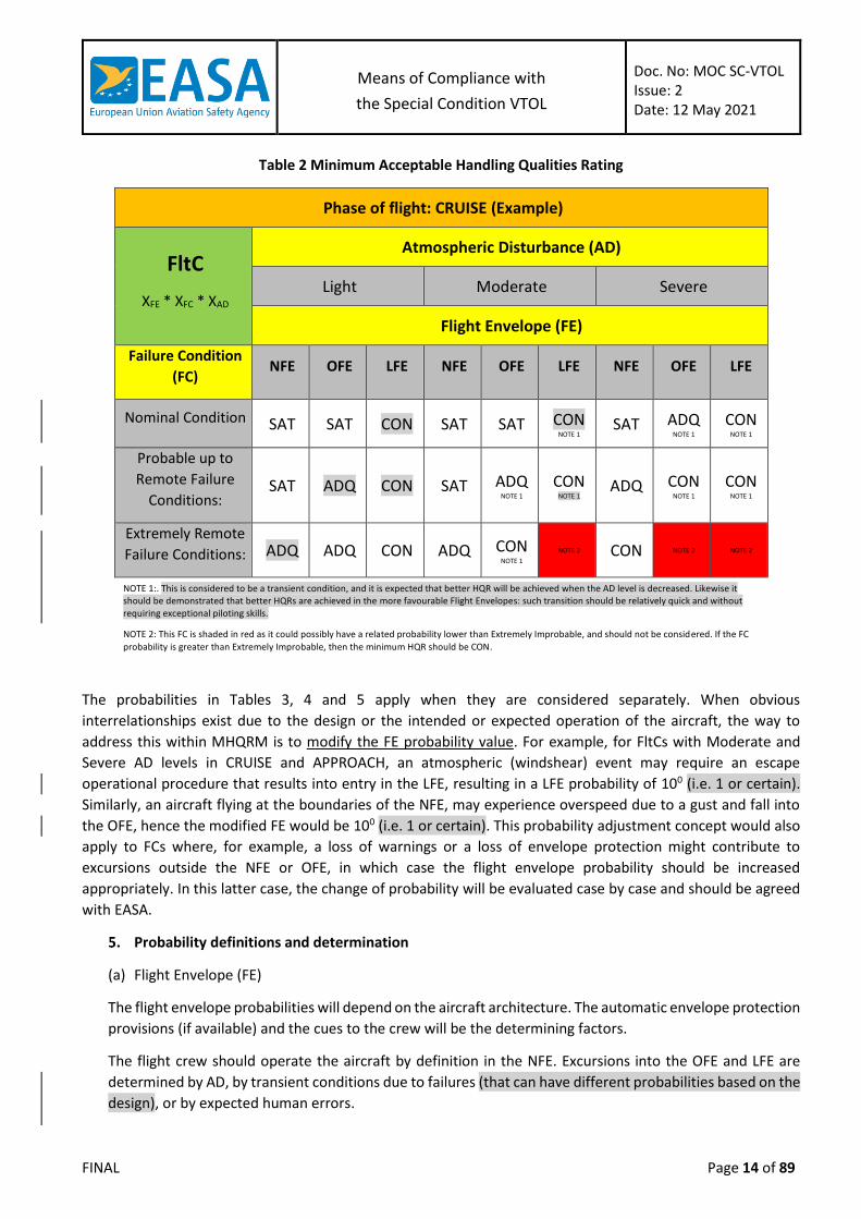
Table 2 is an example for the Cruise phase of flight, and shows the minimum HQR for each FltC, defined as a
combination of the FE and the level of AD, relative to the probability of the FC being evaluated. Similar tables
could be created for the other phases of flight, as the type of FC, most critical from a HQs point of view, could
vary depending on the phase of flight. The minimum HQR for each table will not vary across the different tables,
but, since the FC, FE and AD levels may vary depending on the phase of flight, including the probabilities of
occurrence, it might be beneficial to have different tables or groups of tables depending on the phase of flight .
The different FE are (Table 3): Normal Flight Envelope (NFE), Operational Flight Envelope (OFE) and Limit Flight
Envelope (LFE).
The AD level (Table 4) can be Light, Moderate or Severe.
The FC probabilities (Table 5) are in accordance with the aircraft level MOC VTOL.2510 quantitative probability
values. Probability values for Probable up to Remote Failure Conditions have been grouped together for table
readability reasons, as the minimum HQR would be the same.
It is important to highlight that NOT every combination of AD, FC and FE should be tested.
Means of Compliance with
the Special Condition VTOL
Doc. No: MOC SC-VTOL Issue: 2 Date: 12 May 2021
FINAL Page 14 of 89
Table 2 Minimum Acceptable Handling Qualities Rating
Phase of flight: CRUISE (Example)
FltC
XFE * XFC * XAD
Atmospheric Disturbance (AD)
Light Moderate Severe
Flight Envelope (FE)
Failure Condition
(FC) NFE OFE LFE NFE OFE LFE NFE OFE LFE
Nominal Condition SAT SAT CON SAT SAT CON
NOTE 1 SAT ADQ NOTE 1
CON
NOTE 1
Probable up to
Remote Failure
Conditions: SAT ADQ CON SAT ADQ
NOTE 1 CON
NOTE 1 ADQ CON
NOTE 1 CON
NOTE 1
Extremely Remote
Failure Conditions: ADQ ADQ CON ADQ CON
NOTE 1 NOTE 2 CON NOTE 2 NOTE 2
NOTE 1:. This is considered to be a transient condition, and it is expected that better HQR will be achieved when the AD level is decreased. Likewise it should be demonstrated that better HQRs are achieved in the more favourable Flight Envelopes: such transition should be relatively quick and without requiring exceptional piloting skills.
NOTE 2: This FC is shaded in red as it could possibly have a related probability lower than Extremely Improbable, and should not be considered. If the FC
probability is greater than Extremely Improbable, then the minimum HQR should be CON.
The probabilities in Tables 3, 4 and 5 apply when they are considered separately. When obvious
interrelationships exist due to the design or the intended or expected operation of the aircraft, the way to
address this within MHQRM is to modify the FE probability value. For example, for FltCs with Moderate and
Severe AD levels in CRUISE and APPROACH, an atmospheric (windshear) event may require an escape
operational procedure that results into entry in the LFE, resulting in a LFE probability of 100 (i.e. 1 or certain).
Similarly, an aircraft flying at the boundaries of the NFE, may experience overspeed due to a gust and fall into
the OFE, hence the modified FE would be 100 (i.e. 1 or certain). This probability adjustment concept would also
apply to FCs where, for example, a loss of warnings or a loss of envelope protection might contribute to
excursions outside the NFE or OFE, in which case the flight envelope probability should be increased
appropriately. In this latter case, the change of probability will be evaluated case by case and should be agreed
with EASA.
Probability definitions and determination
(a) Flight Envelope (FE)
The flight envelope probabilities will depend on the aircraft architecture. The automatic envelope protection
provisions (if available) and the cues to the crew will be the determining factors.
The flight crew should operate the aircraft by definition in the NFE. Excursions into the OFE and LFE are
determined by AD, by transient conditions due to failures (that can have different probabilities based on the
design), or by expected human errors.

Means of Compliance with
the Special Condition VTOL
Doc. No: MOC SC-VTOL Issue: 2 Date: 12 May 2021
FINAL Page 15 of 89
These probabilities should be adjusted to account for the interrelationship between AD and FC events
(section 4).
Applicants should provide probabilities based on the evidence that they have available to substantiate them,
and based on their aircraft characteristics.
Visual and aural warnings, or specific aircraft characteristics at the boundaries of the envelopes (vibrations,
noise) could grant credits for increasing the probability of remaining within a given FE.
The probability values proposed by the applicant should be substantiated with actual flight test data.
Table 3: Probability of Occurrence of the Flight Envelope (FE)
Flight Envelope Notes Probability XFE
Normal Flight Envelope (NFE) Generally associated with routine operational and/or prescribed conditions.
At the boundaries of this envelope there could be means to raise the awareness of the crew (cautions).
100
Operational Flight Envelope (OFE)
The crew should be aware that the operation occurs outside the NFE.
At the boundaries of the OFE, warnings and/or EFCS envelope protection means could be present.
The Aircraft Flight Manual (AFM) limitations should be consistent with the boundaries of the OFE.
When considering airspeed to define the envelope, the high speed boundaries of the OFE would be the current Vne.
TBD
Limit Flight Envelope (LFE) The crew should never operate in this envelope; a return should be made at least to the OFE.
This is the maximum extent in terms of envelope that needs to be investigated from a HQ point of view but should not be included in the AFM.
The boundaries of the LFE are associated with aircraft limits.
TBD

Means of Compliance with
the Special Condition VTOL
Doc. No: MOC SC-VTOL Issue: 2 Date: 12 May 2021
FINAL Page 16 of 89
(b) Atmospheric Disturbance (AD)
The atmospheric disturbance level ranges from the complete absence of any disturbance up to the
atmospheric disturbance level (gusts) that are considered for the structural limits of the aircraft. The AD
considered could be different depending on which phase of flight is being evaluated.
Additional steady state relative winds values, for the most critical azimuth, are established to show
compliance with the applicable requirements when the aircraft is operating based on ground references
(e.g. Take-off, Hover, Landing).
The amplitude of the gusts to be considered for the structural design will be defined in MOC VTOL.2215
“Flight Load Conditions”. Non-symmetric gust cases should be considered when evaluating HQ. The shapes
of the gusts may also be a critical factor for HQ and should be evaluated.
The steady state relative wind values are derived from the experience from CS-27, and have been identified
as being 17 kt. This value is the minimum to be used for airworthiness approval; applicants may choose
higher steady wind values based on market requirements.
The steady wind value should be evaluated only in the phases of flight that are close to the ground. The
controllability in steady winds should be demonstrated for all FC in Light AD level (without gusts and
turbulence).
The exact values of the gusts are currently not defined for each AD level. Even the related probabilities (XAD),
which are modified in respect to Appendix E to AC25-7D to account for the Urban Environment, will need to
be verified by recorded data which are currently not available.
Table 4: Probability of Occurrence Guidelines of Atmospheric Disturbance (AD)
Atmospheric Disturbance Notes Probability XAD
Light: No appreciable turbulence and steady state winds less than 3 kt with no appreciable gusts.
100
Moderate: Light to moderate turbulence. Changes in altitude and/or attitude occur. Usually causes variations in indicated airspeed.
TBD
Severe: Turbulence that causes large, abrupt deviations in altitude and/or attitude. Usually causes large variations in indicated airspeeds.
TBD
(c) Aircraft or System Failure Condition affecting HQ (FC)
The Failure Condition probabilities (XFC) relate to the probability of encountering a Failure Condition which
affects HQs. This may include, but is not limited to, the FCS or lift/thrust system. The MHQRM should be
linked to the Safety Assessment Process at aircraft level. Feedback should be provided into the different
Safety Assessment Elements, such as the Functional Hazard Assessment (FHA), Preliminary System Safety
Assessment (PSSA), Fault Tree Analysis (FTA), System Safety Assessment (SSA) or Failure Mode and Effect
Analysis (FMEA), and vice versa to check if the assumptions of these Safety Assessment Elements in terms
of effect (when the driving factor are HQ) are confirmed by the MHQRM evaluation.

Means of Compliance with
the Special Condition VTOL
Doc. No: MOC SC-VTOL Issue: 2 Date: 12 May 2021
FINAL Page 17 of 89
Table 5: Probability of Occurrence Guidelines of Failure Condition affecting HQ (FC)
Failure Condition Notes Probability XFC
Nominal Operation: No failures 100
Up to Major Failure conditions:
Failures with an effect on HQR not more severe than MAJOR.
NOTE 3
Hazardous Failure conditions:
Failures with a HAZARDOUS effect on HQR.
≤10-7 NOTE 3
NOTE 3: The applicant may use any value derived from the safety assessment process, provided it meets the safety objectives. Allowable quantitative probabilities for “probable”, “remote” and “extremely remote” are defined in MOC VTOL.2510 §8

Means of Compliance with
the Special Condition VTOL
Doc. No: MOC SC-VTOL Issue: 2 Date: 12 May 2021
FINAL Page 18 of 89
MOC – SUBPART C – STRUCTURES
MOC VTOL.2200 Structural design envelope
The following design values and limitations should be established to show compliance with the structural
requirements of this Subpart, for each aircraft configuration or flight mode, as appropriate:
(Note: Failure conditions need not be taken into account when defining these design values and limitations.)
(a) The design maximum and design minimum weights.
(b) The lift/thrust units design rpm ranges with power on and power off, if applicable. These design values
should provide adequate margin to accommodate the variations in rpm speed occurring in any
manoeuvre.
(c) Design Airspeeds:
Maximum level flight speed, VH. The maximum level flight speed at maximum continuous
power;
Maximum Design speed, VD.
Never-Exceed speed, VNE. VNE should not be greater than 0.9 times VD.
Velocity of Normal Operations, VNO is the maximum structural cruising speed. VNO should be
defined by the applicant and should be less than or equal to VH and VNE
Maximum design rearward and sideward flight speeds. The maximum design rearward and
sideward speeds should be defined to be no less than 1.11 times the maximum permitted
rearward and sideward speeds.
Design speed for maximum gust intensity, VB (for Category Enhanced). For VB, the following
applies:
(A) VB should not be less than the speed determined by the intersection of the line
representing the maximum positive lift CN MAX and the line representing the rough
air gust velocity on the gust V-n diagram, or VS1√ng , whichever is less, where –
ng the positive aircraft gust load factor due to gust, at speed VNO, and at
the particular weight under consideration; and
VS1 is the stalling speed with the flaps retracted at the particular weight
under consideration.
(B) VB need not be greater than VNO.
(C) If loss of control due to stall is not possible, or definition of VB in accordance with
(A) is not applicable, VB should be defined according to the VTOL operating limit for
flight in turbulent conditions.
(d) The centre of gravity limits corresponding to the configuration of the aircraft.
(e) The rotational speed ratios between each lift/thrust unit and each connected rotating component, as
applicable.
(f) The positive and negative limit manoeuvring load factors should be defined based on the maximum
capability of the aircraft, taking into account the flight control system (without failure cases), for which:
The probability of being exceeded is shown by analysis to be extremely improbable within
the design altitude and temperature range;
Means of Compliance with
the Special Condition VTOL
Doc. No: MOC SC-VTOL Issue: 2 Date: 12 May 2021
FINAL Page 19 of 89
The selected values are appropriate to each weight condition between design maximum
and minimum weights and associated critical centres of gravity; and
The positive load factor is not less than 2.0 and the negative limit manoeuvring load factor
is not less than -0.5.
Note: An absolute maximum positive and negative limit manoeuvring load factor may be proposed for
acceptance by EASA, as appropriate for the aircraft operation and consistent with current Certification
Specifications (e.g. CS 23.337 and CS 27.337).
(g) Ranges of altitudes and temperature for which certification is requested.
(h) Ranges of position of adjustable elements of lift/thrust units and control devices, if applicable.
MOC VTOL.2215 Flight load conditions
The following flight load conditions specify a set of flight conditions to be evaluated to conservatively cover the
most extreme manoeuvring capability of the aircraft. They should be analysed with the aircraft in the most
critical flight phases and flight configurations, in accordance with the design limitations as defined in MOC
VTOL.2200. The flight load cases may be simulated or defined by combining conservative combinations of
parameters, or a combination of these approaches. Full control input ranges should be considered when
determining the flight load cases. The limitations imposed by the flight control system, without failure cases,
may be taken into account.
Failure conditions need not be considered, except as specified in paragraph (g) of this MOC.
If automation systems, such as autopilot upper modes, or a Detect and Avoid system can generate higher control
loads than pilot inputs, the corresponding loads should be taken into account.
Suddenly. For the purposes of this MOC, ‘suddenly’ is defined as the time interval for complete control input
based on a rational analysis, supported by test. For conventional pilot controls, such as stick and pedal,
‘suddenly’ may be assumed as 0.2 seconds for complete control inputs.
(a) Symmetrical Flight Load Conditions: To produce these flight load conditions, the airspeeds should be set
at VD in forward, rearward and sideward flight. The normal load factor should be unity.
(b) Symmetrical pull-up and recovery: To produce these flight load conditions, with the aircraft in an initial
trim condition at forward speeds:
Displace the input control suddenly in order to achieve a nose up motion, to the maximum
deflection as limited by the control stops;
Maintain the maximum input control displacement to allow the aircraft to pitch upwards
and achieve the specified positive manoeuvring load factor; and
Return the input control suddenly to that required for level flight.
The most critical initial trim forward speeds should be evaluated, up to and including VD. This flight load
condition should be evaluated in both power on and power off rpm ranges, if applicable.
The intention of the symmetric pull-up and recovery manoeuvre is to achieve maximum pitch
acceleration, maximum positive normal load factor and maximum aircraft nose-up angle-of attack.
(c) Symmetrical Pushover and Recovery:
To produce these flight load conditions, with the aircraft in an initial trim condition at forward speed :

Means of Compliance with
the Special Condition VTOL
Doc. No: MOC SC-VTOL Issue: 2 Date: 12 May 2021
FINAL Page 20 of 89
Displace the input control suddenly, in order to achieve a nose down motion, to the
maximum deflection as limited by the control stops;
Maintain the maximum input control displacement to allow the aircraft to pitch downwards
and achieve the specified negative manoeuvring load factor; and
Return the input control suddenly to that required for level flight.
The most critical initial trim forward speeds should be evaluated, up to and including VD.
The intention of the symmetric pushover and recovery manoeuvre is to achieve maximum pitch
acceleration, maximum negative normal load factor and maximum aircraft nose-down angle-of attack.
(d) Rolling Flight Conditions (Rolling pull-up and recovery):
To produce these flight load conditions, with the aircraft in an initial trim condition at forward speed:
Displace the input control suddenly, in order to achieve a nose up and rolling moment, to
the maximum deflection as limited by the control stops, or that necessary to achieve a
positive load factor of not less than two-thirds that specified in paragraph (b);
Maintain the control displacements to allow the aircraft to pitch, roll and achieve a positive
manoeuvring load factor of at least two-thirds that specified in (b); and
Return the controls suddenly to those required for level flight.
The maximum rate of roll and the load factor should occur simultaneously. The most critical initial trim
forward speeds should be evaluated, up to and including VD.
The intention of the rolling pull-up and recovery manoeuvre is to achieve maximum pitch acceleration,
maximum roll acceleration with two-thirds of the maximum positive normal load factor.
(e) Yawing Conditions:
To produce these flight load conditions, with the aircraft in an initial trim condition, with zero yaw, at
forward speeds and in the hover:
Displace the input control suddenly, in order to achieve a yawing motion, to the maximum
deflection as limited by the control stops;
Maintain the input control displacement to allow the aircraft to yaw to the maximum
transient sideslip angle;
Allow the aircraft to attain the resulting sideslip angle; and
Return the directional control suddenly to neutral.
Both right and left yaw conditions should be evaluated. The most critical initial trim forward speeds
should be evaluated, from zero up to and including VNE or VH, whichever is less.
Yawing conditions in the hover (spot turns) should be evaluated in both in ground effect (IGE) and out
of ground effect (OGE).
The intention of the yawing condition is to achieve maximum yaw acceleration and maximum aircraft
sideslip angles.
(f) Gust Conditions:
Means of Compliance with
the Special Condition VTOL
Doc. No: MOC SC-VTOL Issue: 2 Date: 12 May 2021
FINAL Page 21 of 89
The aircraft should be designed to withstand, at each critical airspeed up to VD, including
hovering, the loads resulting from vertical and horizontal gusts of 9.14 metres per second
(30 ft/s).
The aircraft should be designed to withstand, at each critical airspeed up to VH or VNE,
whichever is lower, including hovering, the loads resulting from vertical and horizontal gusts
of 15.24 metres per second (50 ft/s).
For Category Enhanced, the aircraft should be designed to withstand, at each critical
airspeed up to VB including hovering, the loads resulting from vertical and horizontal rough
air gusts of 20.12 m/s (66 ft/s)
The aircraft should be designed to withstand 100% of the vertical gust condition of (1) acting
on one side of the aircraft.
The following assumptions should be made:
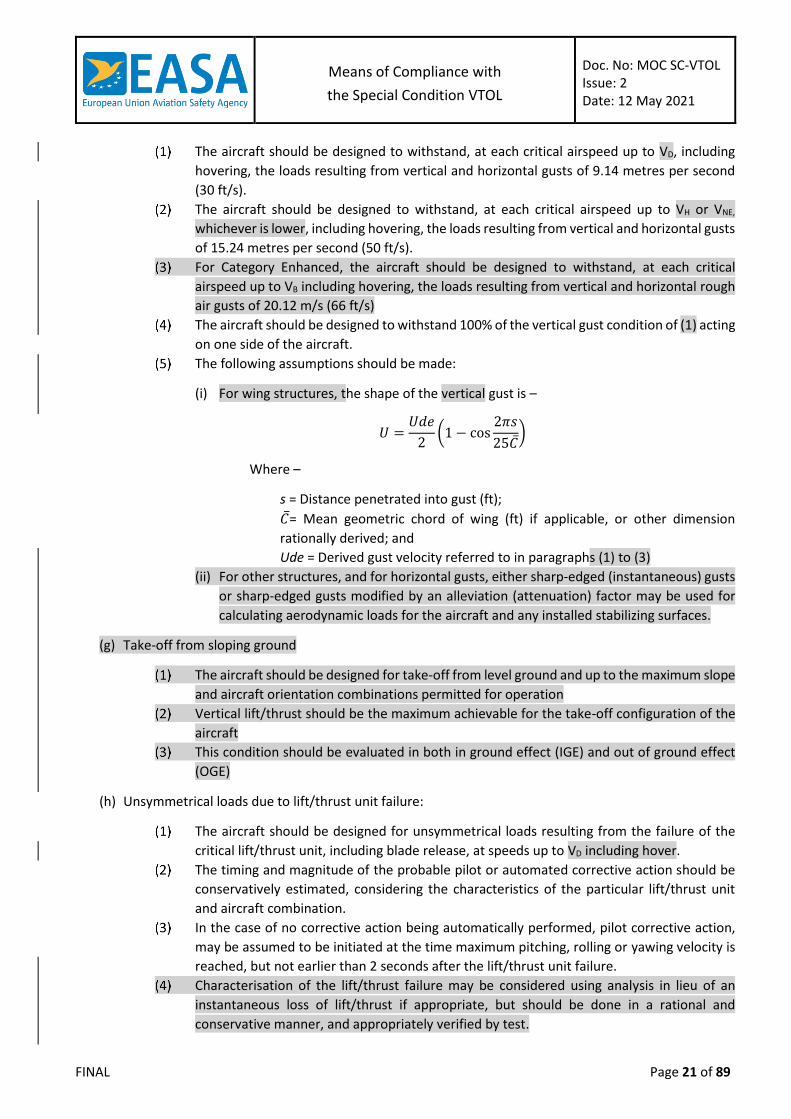
(i) For wing structures, the shape of the vertical gust is –
𝑈 =𝑈𝑑𝑒
2(1 − cos
2𝜋𝑠
25𝐶̅)
Where –
s = Distance penetrated into gust (ft);
𝐶̅= Mean geometric chord of wing (ft) if applicable, or other dimension
rationally derived; and
Ude = Derived gust velocity referred to in paragraphs (1) to (3)
(ii) For other structures, and for horizontal gusts, either sharp-edged (instantaneous) gusts
or sharp-edged gusts modified by an alleviation (attenuation) factor may be used for
calculating aerodynamic loads for the aircraft and any installed stabilizing surfaces.
(g) Take-off from sloping ground
The aircraft should be designed for take-off from level ground and up to the maximum slope
and aircraft orientation combinations permitted for operation
Vertical lift/thrust should be the maximum achievable for the take-off configuration of the
aircraft
This condition should be evaluated in both in ground effect (IGE) and out of ground effect
(OGE)
(h) Unsymmetrical loads due to lift/thrust unit failure:
The aircraft should be designed for unsymmetrical loads resulting from the failure of the
critical lift/thrust unit, including blade release, at speeds up to VD including hover.
The timing and magnitude of the probable pilot or automated corrective action should be
conservatively estimated, considering the characteristics of the particular lift/thrust unit
and aircraft combination.
In the case of no corrective action being automatically performed, pilot corrective action,
may be assumed to be initiated at the time maximum pitching, rolling or yawing velocity is
reached, but not earlier than 2 seconds after the lift/thrust unit failure.
Characterisation of the lift/thrust failure may be considered using analysis in lieu of an
instantaneous loss of lift/thrust if appropriate, but should be done in a rational and
conservative manner, and appropriately verified by test.

Means of Compliance with
the Special Condition VTOL
Doc. No: MOC SC-VTOL Issue: 2 Date: 12 May 2021
FINAL Page 22 of 89
MOC VTOL.2220 Ground and water load conditions
Explanatory Note: In this issue, this MOC addresses ground conditions only; water load conditions will be
defined in a later issue of this MOC.
1. General
(a) Loads and equilibrium. For limit ground loads –
The limit ground loads obtained in this MOC should be considered to be external loads
applied to the aircraft structure as if it were acting as a rigid body; and
If significant, the structural dynamic response of the airframe should be taken into account
considering all critical mass distributions; and
In each specified landing condition, the external loads should be placed in equilibrium with
linear and angular inertia loads in a rational or conservative manner.
(b) Critical centres of gravity. The critical centres of gravity within the range for which certification is
requested should be selected.
2. Ground load conditions and assumptions
(a) For specified landing conditions, all weights should be considered up to the maximum weight. Total lift
may be assumed to act through the centre of gravity throughout the landing impact. This lift may not
exceed two-thirds of the design maximum weight.
(b) Unless otherwise prescribed, for each specified landing condition, the aircraft should be designed for a
limit load factor of not less than the limit inertia load factor substantiated under MOC VTOL.2235 “Limit
drop test”.
3. Tyres and shock absorbers
CS 27.475 Amdt. 6 is accepted as a means of compliance
4. Landing conditions
(a) The following landing conditions apply depending on the configuration of the VTOL
The following landing conditions apply to landing gear with two wheels aft, and one or more
wheels forward, of the centre of gravity:
(i) The level landing conditions in CS 27.479 Amdt. 6 are accepted as means of compliance.
(ii) The tail-down landing conditions in CS 27.481 Amdt. 6 are accepted as means of
compliance.
(iii) The one-wheel landing conditions in CS 27.483 Amdt. 6 are accepted as means of
compliance.
(iv) The lateral drift landing conditions in CS 27.485 Amdt. 6 are accepted as means of
compliance.
(v) The braked roll conditions in CS 27.493 Amdt. 6 are accepted as means of compliance.
The ground loading conditions for landing gear with tail wheels in subparagraphs (a) to (h)
of CS 27.497 Amdt. 6 are accepted as means of compliance.
The ground loading conditions for landing gear with skids in CS 27.501 Amdt. 6 are accepted
as means of compliance.
Means of Compliance with
the Special Condition VTOL
Doc. No: MOC SC-VTOL Issue: 2 Date: 12 May 2021
FINAL Page 23 of 89
(b) CTOL aircraft should be designed for the additional loading conditions specified in this paragraph. In
showing compliance with this paragraph, the following apply:
The level landing conditions in CS 23.479(a) and (b) Amdt. 4 are accepted as a means of
compliance.
The tail down landing conditions in CS 23.481 Amdt. 4 are accepted as a means of
compliance.
The one-wheel landing conditions in CS 23.483 Amdt. 4 are accepted as a means of
compliance.
The sideload conditions in CS 23.485 Amdt. 4 are accepted as a means of compliance.
The braked roll conditions in CS 23.493 Amdt. 4 are accepted as a means of compliance.
The supplementary conditions for tail wheels in CS 23.497 Amdt. 4 are accepted as a means
of compliance.
The supplementary conditions for nose wheels in CS 23.499 Amdt. 4 are accepted as a
means of compliance.
The supplementary conditions for ski-planes in CS 23.505 Amdt. 4 are accepted as a means
of compliance.
(c) The ski landing conditions in CS 27.505 Amdt.6 are accepted as a means of compliance.
5. Taxiing Condition
(a) CS 27.235 Amdt. 6 is accepted as a means of compliance.
(b) In addition, for aircraft with conventional take-off and landing (CTOL) capability the aircraft should be
designed to withstand the loads that would occur when take-offs and landings are performed on
unpaved runways having the roughest surface that may be expected in normal operation.
MOC VTOL.2230 Limit and ultimate loads
The combination of CS 27.301(a) Amdt. 6 and CS 27.303 Amdt. 6 is accepted as a means of compliance.
MOC VTOL.2235 Structural strength
Explanatory Note: At this issue, this MOC addresses landing gear drop test requirements only. Additional MOC
will be added in future issues to address, for example, allowable damages to the aircraft for the Category Basic
controlled emergency landing.
(a) Shock absorption tests: CS 27.723 Amdt. 6 is accepted as a means of compliance.
(b) Limit drop test: CS 27.725 Amdt. 6 is accepted as a means of compliance.
(c) Reserve energy absorption drop test: CS 27.727 Amdt. 6 is accepted as a means of compliance. In
addition:
Shock absorbing devices, such as oleos, should not “bottom” during the reserve energy drop
test. “Bottoming” occurs when displacement of the device no longer occurs with increasing
load. (for further guidance see FAA AC 27.727(a)(3) in FAA AC 27-1B Change 7, which is the
EASA AMC as per Book 2 of CS-27 Amdt. 6)

Means of Compliance with
the Special Condition VTOL
Doc. No: MOC SC-VTOL Issue: 2 Date: 12 May 2021
FINAL Page 24 of 89
Notes:
The proper attitude for the aircraft after the reserve energy absorption drop test is an
attitude which allows for permanent deformation of landing gear elements but provides for
adequate egress from the aircraft (for further guidance see FAA AC 27.727A (b)(1) in FAA
AC 27-1B Change 7, which is the EASA AMC as per Book 2 of CS-27 Amdt. 6).
External accessories that may not impact the landing surface during drop testing include
devices such as externally mounted fuel tanks or accessories that are likely to cause post-
landing fires. Cameras, loudspeakers, and search lights may be damaged during
deformations resulting from reserve energy drop tests if electrical connections are
sufficiently protected to preclude electrical fires and the devices are not likely to penetrate
fuel tanks and other energy sources. The expendable accessories, if installed, should also be
designed to not have “hard points” that would unacceptably damage the aircraft structure
under landing impacts by penetration into the occupied areas or fuel tanks. These
expendable accessories should be designed with frangible fittings, frangible devices, or
comparable design features. Also, these devices should be designed to not significantly alter
the energy absorbing ability or design features of the landing gear (for further guidance see
FAA AC 27.727A (b)(2) in FAA AC 27-1B Change 7, which is the EASA AMC as per Book 2 of
CS-27 Amdt. 6).
External accessories may not contact a level landing surface after “limit landing load”
deflection of the landing gear, i.e. the deflection resulting from the limit drop test described
in paragraph A of this MOC.
MOC VTOL.2240(d) High Energy Fragments – Particular Risk Analysis
The objective of VTOL.2240(d) and this particular risk analysis apply to lift/thrust unit or rotating-machinery
failures, such as propellers, rotors that provide lift, compressor and turbine rotors of turbine engines and APUs
and, electric engine rotor and cooling fans. Service experience of conventional aircraft has shown that damages
due to high-energy fragments, for example following uncontained compressor and turbine rotor failures,
continue to occur. VTOL aircraft have no service experience while the introduction of new technology and
architectures means that VTOL aircraft cannot directly use conventional aircraft service experience to determine
the likelihood and effects of failures. For Category Enhanced the failure of a lift/thrust unit or other rotating-
machinery should therefore be assumed and the corresponding risk should be assessed, in line with the objective
of VTOL.2250(c), with specific considerations for simultaneous or cascading effects presented in this Particular
Risk Analysis. For Category Basic, a lower safety objective, in line withVTOL.2510, is accepted.
Applicants for either Basic or Enhanced category who wish to utilize means to shut down or stop individual rotor
systems to mitigate hazards considered under this risk analysis should ensure that sufficient and reliable
indications, control means and operational procedures are included in the design to allow for correct
identification of a failed or hazardous lift/thrust unit and effective means to meet the analysis assumptions of
imbalance exposure herein (see also MOC VTOL.2425 (b)).
For Category Basic:
The methodology from existing AMC such as AMC 20-128A is accepted for fragment size and trajectory. The
lift/thrust unit or rotating-machinery probability of failure should be compatible with its severity, in accordance

Means of Compliance with
the Special Condition VTOL
Doc. No: MOC SC-VTOL Issue: 2 Date: 12 May 2021
FINAL Page 25 of 89
with VTOL.2510. All consequences of a failure should be considered including possible cascading effects taking
into account the overall probability of failure (Figure 1).
Figure 1: Methodology for the cascading failure evaluation for Category Basic
For Category Enhanced:
(a) Fragments to consider:
A failure of a lift/thrust unit or other rotating-machinery should be assumed. The Safety Analysis should
consider all fragments released with residual energy. For propellers this could be the complete blade from
the aerofoil surface to the retention and any component attached to the blade/hub. This could include
counterweights, clamps, erosion shields, cuffs, de-ice boots, and pitch change pins.
(b) Path and size of fragments:
For turbine engines, the paths and sizes of fragments described in AMC 20-128A and AMC 25.963(e) in Book
2 of CS-25 Amdt. 24 can be used. For propellers and other types of fragments the impact area should be
established based on test, analysis, or both. Applicants may use data from propellers with similar physical
and operating characteristics to establish the impact area.
(c) Hazards:
Hazards from the failure of a lift/thrust unit or other rotating-machinery to be considered should include
damage due to the impact of the high-energy fragments and the imbalance created by such failure. Further
guidance material on engine imbalance, including windmilling considerations, can be found in AMC 25-24.
Applicants may utilize design means of control and stoppage of those lift/thrust units, for which the
probability of failure of those control means is shown to be commensurate with the objectives of VTOL.2510,
and must rationally consider the environment of operation under the expected imbalance conditions.
Pr<objective for
Catastrophic
Second failure Third failure
yes
no
end
Pr compatible
with severity
…
yes
First failure
Pr compatible
with severity
end
Pr = overall probability of the nth failure occurring
…
Pr compatible
with severity
no
Pr<objective for
Catastrophic
Means of Compliance with
the Special Condition VTOL
Doc. No: MOC SC-VTOL Issue: 2 Date: 12 May 2021
FINAL Page 26 of 89
(d) Safety Analysis:
It should be assessed that the failure of a lift/thrust unit or rotating-machinery does not have a catastrophic
effect as defined in MOC VTOL.2510. The assessment should include aircraft systems, structures (including
energy storage), occupants and other lift/thrust units. Due to the distributed propulsion, the failure of a
lift/thrust unit may, for some architectures, potentially cause other lift/thrust failures in a chain reaction.
Specifically the assessment of simultaneous or cascading failures of lift/thrust units can use the following
methodology:
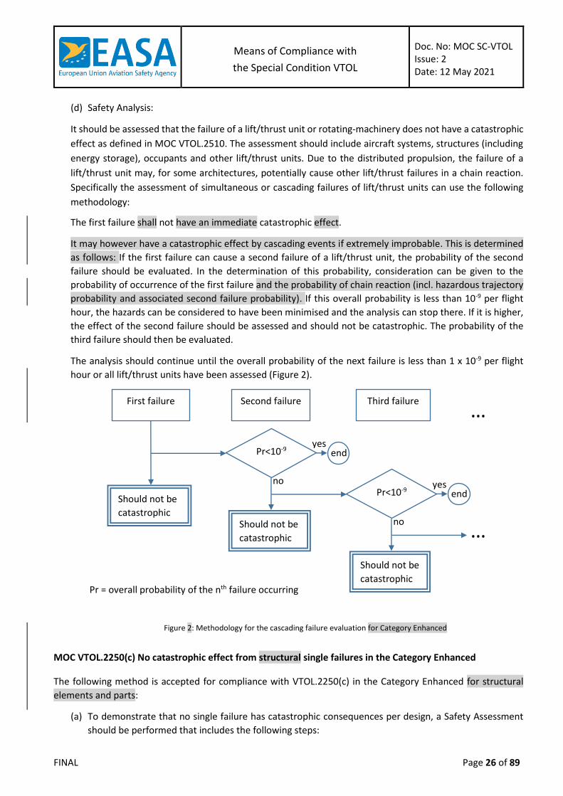
The first failure shall not have an immediate catastrophic effect.
It may however have a catastrophic effect by cascading events if extremely improbable. This is determined
as follows: If the first failure can cause a second failure of a lift/thrust unit, the probability of the second
failure should be evaluated. In the determination of this probability, consideration can be given to the
probability of occurrence of the first failure and the probability of chain reaction (incl. hazardous trajectory
probability and associated second failure probability). If this overall probability is less than 10-9 per flight
hour, the hazards can be considered to have been minimised and the analysis can stop there. If it is higher,
the effect of the second failure should be assessed and should not be catastrophic. The probability of the
third failure should then be evaluated.
The analysis should continue until the overall probability of the next failure is less than 1 x 10⁻⁹ per flight
hour or all lift/thrust units have been assessed (Figure 2).
Figure 2: Methodology for the cascading failure evaluation for Category Enhanced
MOC VTOL.2250(c) No catastrophic effect from structural single failures in the Category Enhanced
The following method is accepted for compliance with VTOL.2250(c) in the Category Enhanced for structural
elements and parts:
(a) To demonstrate that no single failure has catastrophic consequences per design, a Safety Assessment
should be performed that includes the following steps:
First failure Second failure Third failure
Should not be
catastrophic
no fatality
Pr<10-9 yes
no
end
Should not be
catastrophic …
…
Pr = overall probability of the nth failure occurring
Pr<10-9 yes
no
end
Should not be
catastrophic

Means of Compliance with
the Special Condition VTOL
Doc. No: MOC SC-VTOL Issue: 2 Date: 12 May 2021
FINAL Page 27 of 89
a complete and comprehensive list of structural elements or parts and their interfaces
should be provided;
the functions that the structural elements or parts perform should be identified; and
a safety assessment should be performed to identify all structural elements and parts for
which failure could lead to Catastrophic consequences. All reasonably anticipated and
conceivable failures modes should be taken into account, and all the stages of flight and
operating conditions should be considered.
The conclusions of the Safety Assessment should demonstrate the non-catastrophic
classifications of all single failures and thereby show direct compliance with VTOL.2250 (c).
If any single failure is identified that can lead to a catastrophic consequence:
(i) a structural redesign or vehicle re-configuration should be considered.
(ii) For simply loaded static elements(1) that are not involved in a system function, if
redesign or reconfiguration is impractical or adds excessive design complexity that
would impair the overall safety objective, it should be demonstrated that catastrophic
consequences from any single failure are extremely improbable applying a combination
of the compensating provisions in accordance with paragraph (b).
Note (1): Simply loaded static elements are typically airframe components. They are not
high cycle fatigue loaded, non-rotating and not complexly loaded such as control
surfaces or blades.
(b) For structural elements or parts and failure modes identified in (a)(5)(ii), compensating provisions
acceptable to EASA may be selected from the non-exhaustive list below:
Design features; (e.g., safety factors, part-derating criteria, etc.)
Fatigue tolerance evaluation
Operational limitations
An inspection or check that would detect the failure mode or evidence of conditions that
could cause the failure mode
A preventive maintenance action to minimise the likelihood of occurrence of the failure
mode, including replacement actions and verification of serviceability of items which may
be subject to a dormant failure mode
Special assembly procedures or functional tests for the avoidance of assembly errors which
could be safety critical
Other safety devices
MOC VTOL.2250(f) Aircraft capability after bird impact
This MOC provides methods to demonstrate the remaining capability of the aircraft after a bird impact as
required by VTOL.2250(f).
It is applicable to VTOL Aircraft in the Category Basic designed to carry 7 to 9 passengers and in the Category
Enhanced.
1. Single bird strike evaluation:
(a) In accordance with VTOL.2250(f), VTOL aircraft must be designed to ensure the capability of a controlled
emergency landing in the Category Basic with a maximum of 7 or more seats, or of a continued safe
flight and landing in the Category Enhanced, after impact of a 1.0-kg (2.2-lb) bird. This should be ensured

Means of Compliance with
the Special Condition VTOL
Doc. No: MOC SC-VTOL Issue: 2 Date: 12 May 2021
FINAL Page 28 of 89
in the most critical configuration for the corresponding velocity of the VTOL (relative to the bird along
the flight path of the vehicle) up to the maximum speed in level flight with maximum continuous power,
at operating altitude up to 2438 m (8,000 ft.).
(b) Compliance should be shown by tests or by analysis based on tests carried out on sufficiently
representative structures of a similar design.
(c) The following parts should be evaluated for a single bird strike:
The windshield directly in front of occupants and the supporting structures for these panels
should be capable of withstanding a bird impact without penetration for maximum speeds
above 50kt.
Other structures, systems and equipment should also be evaluated. The selection of the
areas to be substantiated should be the result of a comprehensive hazard analysis based
on:
(i) Exposed areas of the structure and internal equipment and systems inside of these
exposed areas in case of bird penetration or shock loads; and
(ii) Their criticality and their ability to ensure continued safe flight and landing (for Category
Enhanced) or controlled emergency landing (for Category Basic).
(d) When performing the hazard analysis, direct and induced effects of a bird strike should be considered:
"Direct Effects": to ensure the integrity of the structure and functionality of systems or
equipment (including consideration of shock loads) which are critical for continued safe
flight and landing (for Category Enhanced) or controlled emergency landing (for Category
Basic).
"Induced Effects": to examine the possible consequences of the ejection of pieces from
structures, systems or equipment which are struck by a bird on other structures and
systems. For a bird impact on the lift/thrust system, the guidance in MOC VTOL.2240(d) can
be followed, when relevant, in the demonstration of compliance mentioned in paragraph
(a) of this section.
2. Multiple bird strike evaluation:
(a) VTOLs are generally equipped with redundant systems and structures. To ensure continued safe flight and
landing (for Category Enhanced) or controlled emergency landing (for Category Basic) following a multiple
bird strike, an evaluation should be performed of the effects of such multiple bird strike in the most critical
configurations for the corresponding velocity of the VTOL up to the maximum speed in level flight with
maximum continuous power, within the range of airspeed for normal operation up to 4000ft MSL (Mean
sea level).
(b) The applicant should consider potentially vulnerable redundant systems and structures and their effective
exposed area (wing, lift surfaces, rudder, ailerons…).
(c) An acceptable approach is to show that there is no loss of function of the element that is impacted after a
single impact with a medium sized bird of 0.450 kg. Alternatively, scenarios evaluating multiple bird impacts
distributed across each structure or system can be proposed by the applicant considering medium birds and
small birds according to the MOC VTOL.2400 guidance (see Figure 1). Multiple bird strike evaluation is not
required for the windshield.

Means of Compliance with
the Special Condition VTOL
Doc. No: MOC SC-VTOL Issue: 2 Date: 12 May 2021
FINAL Page 29 of 89
Figure 1- Overview of the Airframe and Propulsion System guidance interaction for compliance to bird strike
MOC VTOL.2270(a) and (c) Emergency landing conditions: General considerations
This MOC provides a set of general design conditions that, when used in their entirety, are accepted to ensure
adequate protection of occupants against injuries that would prevent egress in an emergency landing.
(a) CS 27.561(a) Amdt. 6 is accepted as a means of compliance.
(b) CS 27.561(b) Amdt. 6 is accepted as a means of compliance with the addition under subparagraph (3)(ii) of
a 18 g ultimate inertial load factor in the forward direction for CTOL aircraft.
(c) CS 27.561(c) Amdt. 6 is accepted as a means of compliance replacing “rotors, transmissions and engines” by
“lift/thrust units, transmissions and energy storage systems”.
(d) CS 27.561(d) Amdt. 6 is accepted as a means of compliance replacing “fuel tanks” by “energy storage
systems”.
(e) For CTOL, CS 23.561(d) Amdt. 4 is accepted as a means of compliance.
MOC VTOL.2270(b)(1) Emergency landing dynamic conditions
This MOC provides a set of general design conditions that, when used in their entirety, are accepted to ensure
adequate protection of occupants against injury in dynamic conditions that are likely to occur in an emergency
landing.
(a) CS 27.562(a) Amdt. 6 is accepted as a means of compliance.
(b) CS 27.562(b) Amdt. 6 is accepted as a means of compliance under the following conditions:
CS 27.562(b)(1) Amdt. 6 is accepted as a means of compliance, noting that the 30 g at seat
attachment level was based upon the typical underfloor structure of a conventional
rotorcraft. Therefore the 30 g is only valid if the structure underneath the seats has equal
or better damping characteristics than a conventional rotorcraft. If specific design features
are integrated, less than 30g at the seat may be acceptable based on analysis supported by
tests
CS 27.562(b)(2) Amdt. 6 is accepted as a means of compliance with the following addition:
For CTOL peak floor deceleration should occur in not more than 0.05 seconds after impact
and should reach a minimum of 26 g. For CTOL seat/restraint systems not being in the first
row, peak deceleration should occur in not more than 0.06 seconds after impact and should
reach a minimum of 21 g.
CS 27.562(b)(3) Amdt. 6 is accepted as a means of compliance.
(c) CS 27.562(c) Amdt. 6 is accepted as a means of compliance.
VTOL.2250(f) in SC-VTOL
MOC VTOL 2250 (f) MOC VTOL 2400 (b)
EHPS.290 in SC-E19-EHPS
MOC EHPS.290

Means of Compliance with
the Special Condition VTOL
Doc. No: MOC SC-VTOL Issue: 2 Date: 12 May 2021
FINAL Page 30 of 89
(d) CS 27.562(d) Amdt. 6 is accepted as a means of compliance.
MOC VTOL.2270(e) Cargo and baggage compartments
The following provisions provide a set of design criteria that, when used in their entirety, are accepted to ensure
compliance of the baggage compartment design with VTOL.2270(e):
(a) CS 27.787 Amdt. 6 is accepted as a means of compliance.
(b) CS 27.855(b) Amdt. 6 is accepted as a means of compliance.
(c) For CTOL, in addition to (a) and (b), CS 23.787 Amdt. 4 is accepted as a means of compliance

Means of Compliance with
the Special Condition VTOL
Doc. No: MOC SC-VTOL Issue: 2 Date: 12 May 2021
FINAL Page 31 of 89
MOC – SUBPART D – DESIGN AND CONSTRUCTION
MOC 1 VTOL.2300 Fly-by-Wire control systems: Definition and Scope
The definition of flight control system is provided in MOC VTOL.2000.
Due to the distributed propulsion, most VTOL configurations have a closer integration of engines and flight
controls than other types of aircraft. To address this specificity, a number of lift/thrust system and flight control
system objectives are included in Subpart F – Systems and equipment objectives.
While some definitions are proposed in this MOC to facilitate common references, they do not imply limits in
the scope of analyses. For example, in most configurations, the lift/thrust units play a role in the flight control
function and should thus be integrated in any related safety analyses (e.g. MOC VTOL.2510, MOC 4 VTOL.2300).
Scope and certification approach covering both engines and flight controls for each project should be proposed
by the Applicant for acceptance by EASA.
MOC 2 VTOL.2300 Acceptability of ASTM standard F3232/F3232M-20 for Fly-by-Wire flight control systems
Status and comments
The ASTM F3232/F3232M-20 standard is the Standard Specification for Flight Controls in Small Aircraft. As this
standard was prepared with the assumption of traditional (i.e. mechanical) primary flight controls, it can only
be accepted as a means of compliance with VTOL.2300 for Fly-by-Wire (FbW) control systems with some
explanations (see below), adaptations and additions (see Section 2) .
The definitions provided in §3 of ASTM F3232/F3232M-20 are only applicable insofar as the concept exists for
VTOL aircraft and has not been defined otherwise. For instance: “aircraft type code” is not a valid concept for
VTOL and “Continued Safe Flight and Landing” has been specifically defined for VTOL aircraft in MOC VTOL.2000.
Similarly, any reference in ASTM F3232/F3232M-20 to standards or methods for the determination of Handling
Qualities should be considered to be replaced by a reference to MOC VTOL.2135.
Lastly, while this standard addresses conventional architecture elements such as flaps and stall barrier systems,
different considerations may apply for other architectures in VTOL aircraft.
The following table provides the status of the acceptability of the ASTM F3232/F3232M-20 standard as a means
of compliance with VTOL.2300 for Fly-by-Wire (FbW) control systems. Later revisions of ASTM F3232/F3232M
or alternative standards may also be proposed by the applicant and agreed with EASA as acceptable means of
compliance in a particular certification project.

Means of Compliance with
the Special Condition VTOL
Doc. No: MOC SC-VTOL Issue: 2 Date: 12 May 2021
FINAL Page 32 of 89
ASTM F3232/F3232M-20 VTOL status/comments
§4.1.1, §4.1.2 Accepted
§4.1.3, §4.1.3.1 Accepted
§4.2 This ASTM standard paragraph is an accepted means of compliance. Nevertheless, additional means of compliance are required for FbW, as proposed in this MOC.
§4.3 Accepted
§4.4 Accepted
§4.5 Accepted
§4.6 Accepted
§4.7 This ASTM § was developed for traditional flight control systems. It is accepted as with some additions, see Section 2 below .
§4.8 Accepted
§4.9 Typo in the ASTM standard: “flight” instead of “light”. Accepted
§4.10 Accepted
§4.11 Accepted
§4.12 Accepted
§4.13 Accepted
§5.1 Accepted
§5.2 Accepted with some additions to address FbW
§5.3 Artificial Stall Barrier System
Accepted
Adaptations/additions to ASTM standard F3232/F3232M-20 linked to Fly-by-Wire implementation
(a) Operation tests
To be considered an accepted means of compliance with VTOL.2300(a)(1) and (2), paragraph §4.7 of
ASTM standard F3232/F3232M-20 should be adapted and complemented as follows:
Adaptation of ASTM F3232/F3232M-20 standard
4.7 Operation Tests:
4.7.1 It must be shown by operation tests that, when the controls are operated from the pilot
compartment with the system loaded to the maximum actuation system forces (i.e. loads and
torques), the system is free from jamming, excessive friction, excessive deflection, or any
combination thereof.
NOTES:
(i) It is acceptable to reduce the load slightly to enable movement of the actuator
throughout its range.
(ii) This requirement applies to primary and secondary flight controls that move surfaces
and flight controls that move or redirect lift/thrust units. It does not apply to fixed
propulsion units that vary RPM, blade angle, or thrust for flight control.
Means of Compliance with
the Special Condition VTOL
Doc. No: MOC SC-VTOL Issue: 2 Date: 12 May 2021
FINAL Page 33 of 89
Addition to ASTM F3232/F3232M-20 standard
One method, but not the only one, for demonstrating the Operational Tests is as follows:
Conduct the control system operational tests by operating the controls from the pilot's
compartment with the entire system loaded so as to correspond to the limit control forces
established by the regulations for the control system being tested. The following conditions
should be met:
(i) Under limit load, check each control surface/effector for travel and detail parts for
deflection. This may be accomplished as follows:
(A) Support the control surface/effector being tested while positioned at the neutral
position.
(B) Load the surface using loads corresponding to the limit control forces established in
the SC VTOL.
(C) Load the pilot's control until the control surface is just off the support.
(D) Determine the available travel which is the amount of movement of the
surface/effector from neutral when the control is moved to the system stop. It is
acceptable to reduce the load slightly to enable movement of the actuator
throughout its range.
(E) The above procedure should be repeated in the opposite direction.
(F) The minimum control surface/effector travel from the neutral position in each
direction being measured should be 10 percent of the control surface travel
measured with no load on the surface.
Regardless of the amount of travel of the surface when under limit load, the aircraft
should have adequate flight characteristics as specified in Subpart B. Any derivative
aircraft of a previous type certificated aircraft need not exceed the control surface
travel of the original aircraft; however, the flight characteristics should be flight
tested to ensure compliance.
(ii) Under limit load, no signs of jamming or of any permanent set of any connection, bracket,
attachment, etc. may be present.
(iii) Friction should be minimised so that the limit control forces and torques specified by the
regulations may be met.
MOC 3 VTOL.2300 Validation of Electronic Flight Control Laws (FCL) in Fly-by-Wire flight control systems
Compliance of the electronic flight control laws should be considered satisfactory when an adequate
substantiation of validation activities is shown and formalised in the compliance documents.
(a) Formalisation of compliance demonstration strategy
In order to demonstrate compliance with an adequate level of formalisation, the following should be
performed and captured within compliance documents:
Determination of flight control characteristics that require a detailed and specific validation
strategy for VTOL.2135, VTOL.2145, VTOL.2300, VTOL.2500, VTOL.2510 compliance and
Modified Handling Qualities Rating Method (MHQRM) demonstration;

Means of Compliance with
the Special Condition VTOL
Doc. No: MOC SC-VTOL Issue: 2 Date: 12 May 2021
FINAL Page 34 of 89
Substantiation of the proposed validation strategy (e.g. analyses, simulator tests, flight
tests) covering the characteristics and features determined above.
(b) Validation activities
For the substantiation of the proposed validation strategy, the applicant should perform the following
activities:
Identify the objectives (intended function) of each function.
Check proper integration of each FCL function in the EFCS (Electronic Flight Control System)
against objectives (e.g. rig-test, offline/piloted simulation, flight test, …).
Check compatibility of each function with other functions acting on the same control
surface/actuator:
(i) Identify potential interface problems with other functions,
(ii) Define test conditions (e.g. rig-test, offline/piloted simulation, flight test, …),
(iii) Particular consideration should be given to actuator limitations and the resulting
coupling of the remaining control authority between different control functions.
Check compatibility of each function in all applicable modes with other functions at aircraft
level:
(i) Identify potential interface problems with other functions on aircraft level,
(ii) Define test conditions (e.g. rig-test, offline/piloted simulation, flight test, …).
Analyse failure conditions for each function:
(i) Identify failure conditions and classify the severity of failures in accordance with
VTOL.2510,
(ii) Define test conditions for verification of failure conditions severities (e.g. rig-test,
offline/piloted simulation, flight test, …).
(iii) Where functions are acting on the same control surface/actuators, particular
consideration shall be given to coupling of failures in these functions (including control
margin dependencies) as well as the overall redundancy management between these
functions (including actuator limitations).
Document all steps.
(c) Characteristics
For the validation activities identified by the paragraphs (b) (2) to (5) above, the following should be covered
in particular:
Definition of priorities between FCL functions acting on the same control surface / actuator
(e.g. priorities, mixing-laws, …),
Multi-objective optimisation (e.g. trajectory, energy consumption, passenger comfort),
including trading one criterion (e.g. airspeed) vs others in extreme conditions,
Transition between different FCL modes with and without failures (e.g. blending, fading-
in/fading-out, smoothness of transition, …),
Effects of erroneous input data (e.g. air data, aircraft configuration, …),
Discontinuities and non-linearities,
Control law interfaces,
Means of Compliance with
the Special Condition VTOL
Doc. No: MOC SC-VTOL Issue: 2 Date: 12 May 2021
FINAL Page 35 of 89
Voting mechanisms,
Protections priorities (e.g. entry/exit logic conditions not symmetrical),
Determination of critical scenario for multiple failures.
The validation strategy should include but should not be limited to operational scenarios. The determination
that an adequate level of validation of the FCL design has been achieved should be based on engineering
judgment.
(d) Documentation to be provided
The applicant should prepare a checklist with a defined set of test cases based on experience, and provide
the FCL Validation methodology and strategy for verification by EASA.
(e) Auditing
The Applicant should perform adequate auditing and EASA may define a related Level of Involvement in
such audits.
Compliance should be shown in conjunction with the following requirements: VTOL.2135, VTOL.2145, VTOL.2500 and VTOL.2510.
MOC VTOL.2300(a)(1) Function and operation of Fly-by-Wire flight control system
(a) Flight crew awareness of the modes of operation
If the design of the flight control system has multiple modes of operation (e.g. hover,
transition, cruise modes) and/or includes degraded modes following failures, a means
should be provided to indicate to the crew any mode that significantly changes or degrades
the handling or operational characteristics of the aircraft.
The sub-modes of operation (both in nominal and degraded mode) and the transition
between them should be smooth, and should be evaluated to determine whether or not
they are intuitive. If these sub-modes or the transition between them are not intuitive, an
indication to the flight crew may be required. This indication may be different from the
classic “failure alerting”.
In case of several flight control modes, limitations should be clearly annunciated and the
definition of a Training Area of Special Emphasis (TASE) in the Flight Crew Data (FCD) may
need to be established during the certification of the Operational Suitability Data (OSD).
Compliance should be shown in conjunction with other paragraphs (such as VTOL.2445), where
failures could lead to flight control mode degradation.
(b) Flight envelope protection
If Flight Envelope Protection (FEP) features are implemented, then these should follow the following
principles:
Onset characteristics of each envelope protection feature should be smooth, appropriate
to the phase of flight and type of manoeuvre; and not be in conflict with the ability of the
pilot to satisfactorily change the aircraft flight path (e.g. speed, attitude) within the
approved flight envelope.

Means of Compliance with
the Special Condition VTOL
Doc. No: MOC SC-VTOL Issue: 2 Date: 12 May 2021
FINAL Page 36 of 89
Limit values of protected flight parameters (and if applicable, associated warning
thresholds) should be compatible with:
(i) the aircraft structural limits;
(ii) the required safe and controllable manoeuvring of the aircraft;
(iii) the margins to critical conditions;
(iv) dynamic manoeuvring, airframe and system tolerances (both from manufacturing and
in-service), and non-steady atmospheric conditions - in any appropriate combination
and phase of flight - should not result in a limited flight parameter beyond the nominal
design limit value that would cause unsafe flight characteristics;
(v) the rotor rotational speed limits;
(vi) the blade stall limits;
(vii) the engine and transmission torque limits; and/or
(viii) any other operation limitations for the aircraft and lift/thrust system installation.
The aircraft should be responsive to pilot commanded dynamic manoeuvring within a
suitable range of the parameter limits that define the approved flight envelope.
The FEP system and any failure condition not shown to be extremely improbable should be
analysed per MOC VTOL.2135 MHQRM (including the effect on flight envelope probabilities)
and VTOL 2510.
When simultaneous envelope limiting is active this should not result in adverse coupling or
adverse priority (e.g. if two or more envelope limitations could exist simultaneously, this
consequence should not be a wrong priority).
Adherence to the above principles should be shown in conjunction with the demonstration of
compliance with the following requirements: VTOL.2110, VTOL.2425(a), VTOL.2500, VTOL.2510(a)(b)
and VTOL.2135 with MOC VTOL.2135.
(c) Flight control and critical displays:
The following apply at all attitudes and in all modes of operation:
The flight control system should be designed to continue to operate and not hinder aircraft
recovery from any attitude.
Control systems for essential services should be designed so that when a movement to one
position has been selected, a different position can be selected without having to wait for
the completion of the initially selected movement, and the system should arrive at the
finally selected position without further attention. The movements that follow and the time
taken by the system to allow the required sequence of selection should not be such as to
adversely affect the airworthiness of the aircraft.
Compliance should be shown by evaluation of the closed loop flight control system. This
evaluation is intended to ensure that there are no features or unique characteristics
(including numerical singularities) which would restrict the pilot’s ability to recover from
any attitude. The intent is not to limit the use of envelope protection features or other
systems that augment the control characteristics of the aircraft.
The following conditions that might occur due to pilot action, system failures or external
events should be considered:
(i) Abnormal attitude (including the aircraft becoming inverted);
(ii) Excursion of any other flight parameter; and

Means of Compliance with
the Special Condition VTOL
Doc. No: MOC SC-VTOL Issue: 2 Date: 12 May 2021
FINAL Page 37 of 89
(iii) Flight conditions that may result in higher than normal pitch, roll or yaw rates.
For each of the conditions in (c)(4):
(i) The flight control system should continue to operate;
(ii) The design of the flight control laws, including any automatic protection function should
not hinder aircraft recovery; and
(iii) Critical flight displays should continue to provide accurate indications and any other
information that the pilot may require to execute recovery from the unusual attitude
and/or arrest the higher than normal pitch, roll or yaw rates.
MOC VTOL.2300(a)(2) Protection against likely Hazards for Fly-by-Wire flight control systems
(a) Control Signal Integrity
Perturbations, as referred to in this MOC, are described as signals that result from any condition that is
able to modify the command signal from its intended characteristics. They can be categorised into the
following categories:
Internal causes that could modify the command and control signals. These include but are
not limited to:
(i) loss of data bits, frozen or erroneous values,
(ii) unwanted transients,
(iii) computer capacity saturation,
(iv) processing of signals by asynchronous microprocessors,
(v) adverse effects caused by transport lag,
(vi) poor resolution of digital signals,
(vii) sensor noise,
(viii) corrupted sensor signals,
(ix) aliasing effects,
(x) inappropriate sensor monitoring thresholds,
(xi) structural interactions (such as control actuator compliance or coupling of structural
modes with control modes), that may adversely affect the system operation or
structural stability and integrity.
External causes that could modify the command and control signals. These include but are
not limited to:
(i) Lightning,
(ii) EMI effects (e.g., electric engine interference, aircraft’s own electrical power and
power switching transients, smaller signals if they can affect flight control, transients
due to electrical failures),
(iii) High Intensity Radiated Fields (HIRF)
(iv) Single Event Effects (SEE)
Spurious signals and/or false data, that are a consequence of perturbations in either of the
two categories above, may result in malfunctions that produce unacceptable system
responses equivalent to those of conventional systems such as limit cycle/oscillatory
failures, runaway/hardover conditions, disconnection, lockups and false indication/warning

Means of Compliance with
the Special Condition VTOL
Doc. No: MOC SC-VTOL Issue: 2 Date: 12 May 2021
FINAL Page 38 of 89
that consequently present a flight hazard. It is imperative that the command signals remain
continuous and free from internal and external perturbations and common cause failures.
Therefore special design measures should be employed to maintain system integrity at a
level of safety at least equivalent to that which is achieved with traditional hydro-
mechanical designs. These special design measures can be monitored through the System
Safety Analysis (SSA) process provided specific care is directed to development methods
and on quantitative and qualitative demonstrations of compliance.
An evaluation of the following should be conducted:
(i) The flight control system should continue to perform its intended function (even in a
degraded mode), regardless of any malfunction from sources in the integrated systems
environment of the aircraft.
(ii) Any system in the aerodynamic loop which has a malfunction should not produce an
unsafe level of uncommanded motion and should automatically recover its ability to
perform critical functions upon removal of the effects of that malfunction.
(iii) Malfunctions of systems in the aerodynamic loop should not adversely affect the
ability to perform a safe flight and landing.
(iv) Any disruption to an individual unit or component as a consequence of a malfunction,
and which requires annunciation and crew action, should be identified to and
approved by EASA to ensure that:
(A) the failure can be recognised by the crew, and
(B) the crew action can be expected to result in continued safe flight and landing in the
Category Enhanced or in a controlled emergency landing in the Category Basic.
(v) An automatic change from a normal to a degraded mode that is caused by spurious
signal(s) or malfunction(s) should meet the probability requirements associated with
the functional hazard assessment (FHA) established per VTOL.2510(a), (e.g. a failure
condition assessed as major should be remote).
(vi) Exposure to a spurious signal or malfunction should not result in a hazard with a
probability greater than that allowed by the criteria of VTOL.2510(a) and associated
MOC. The impact on handling qualities and structural loads should also be evaluated.
(vii) Interaction of flight control functions and actuator control loops
(viii) The flight control system should operate appropriately when considering other
systems. The applicant should ensure the compatibility of automatic functions that
may dynamically interact or affect flight control in both normal and anticipated
abnormal operating conditions and ensure that such interactions (either by aircraft
response or by data transfer) do not result in inappropriate flight control responses.
This should include any potential for adverse coupling of the dynamics of one
automated flight function with another (e.g., coupling between automated power
and flight control functions).
The complexity and criticality of the FbW flight control system (if utilised) necessitates
additional laboratory testing beyond that required as part of individual equipment
validation and software verification.
It should be shown that either the FbW flight control system signals cannot be altered
unintentionally (i.e. what is received by the effector/actuator is what was transmitted by
the computer), or that altered signal characteristics meet the following criteria:

Means of Compliance with
the Special Condition VTOL
Doc. No: MOC SC-VTOL Issue: 2 Date: 12 May 2021
FINAL Page 39 of 89
(i) Stable gain and phase margins are maintained for all flight control closed loop
systems. Pilot control inputs (pilot in the loop) are excluded from this requirement.
(ii) Sufficient pitch, roll, yaw and lift/thrust control power is available to provide control
for continued safe flight and landing in the Category Enhanced or for controlled
emergency landing in the Category Basic, considering all the FbW flight control
system signal malfunctions that are not extremely improbable.
(iii) The effect of spurious signals on the systems which are included in the aerodynamic
loop should not result in unacceptable transients or degradation of the aircraft's
performance. Specifically, signals that would cause a significant uncommanded
motion of a control surface/effector actuator should be readily detected and
deactivated or the surface motion should be arrested by other means in a satisfactory
manner. Small amplitude residual system oscillations may be acceptable, if justified.
(iv) Establishment of a Validation and Verification process for the development of the
flight control monitors, for example following SAE ARP 6539 Validation and
Verification Process Steps for Monitors Development in Complex Flight Control and
Related Systems.
It should be demonstrated that the output from the control surface closed loop system does
not result in any uncommanded, sustained oscillations of flight control surfaces/effectors.
The effects of minor instabilities may be acceptable, provided that they are thoroughly
investigated, documented, and understood. An example of an acceptable condition would
be one where a computer input is perturbed by spurious signals, but the output signal
remains within the design tolerances, and the system is able to continue in its selected mode
of operation unaffected by that perturbation.
In the context of showing and demonstrating these system characteristics an accepted
Means of Compliance includes:
(i) Systematic laboratory validation which includes a realistic representation of all
relevant interfacing systems, and associated software, including the control system
components which are part of the lift/thrust system. Closed loop aircraft
simulation/testing will be necessary in this laboratory validation.
(ii) Laboratory or aircraft testing to demonstrate unwanted coupling of electronic
command signals (over the spectrum of operating frequencies) and their effects on the
mechanical actuators and interfacing structure.
(iii) Analysis or inspection to substantiate that separation/segregation are utilised to
minimize any potential hazards.
A successful demonstration of signal integrity should include all elements, which contribute
to command and control signals to the "aerodynamic closed loop" that actuate the flight
controls. The "aerodynamic closed loop" should be evaluated for the normal and degraded
modes. Elements of the integrated "aerodynamic closed loop" may include for example;
digital or analogue flight control computers, power control units, control feedback, major
data busses, and the sensor signals including; air data, acceleration, rate gyros, commands
to the surface position, and respective power supply sources. Autopilot systems (including
feedback functions) should be included in this demonstration if they are integrated with the
FbW flight control system.

Means of Compliance with
the Special Condition VTOL
Doc. No: MOC SC-VTOL Issue: 2 Date: 12 May 2021
FINAL Page 40 of 89
Compliance should be shown in conjunction with VTOL.2510 and SC EHPS (Electric and Hybrid
Propulsion System).
(b) Pre-flight check
A means should be provided to allow a check of full range of movement to their commanded position
of all primary lift/thrust controls (i.e. pilot controls, control surfaces) prior to flight, or a means should
be provided that will allow the pilot to determine that full control authority is available prior to flight.
Some checks of the engine power and power control (e.g. engine RPM at least at idle thrust) should also
be provided.
Compliance should be shown in conjunction with the following requirements VTOL.2425(a),
VTOL.2435(f) (g) and VTOL.2615.
(c) Precautions against maintenance error / incorrect assembly
Experience has shown that maintenance errors should be assumed to occur and should be considered
in the system design in order to reduce their likelihood.
The flight control system should be designed to physically prevent incorrect assemblies having
significant safety effects and/or critical repercussions (i.e. catastrophic, hazardous, or major). Distinctive
and permanent marking should only be used if the prevention of incorrect assembly by design is
impractical, and EASA accepts the justification provided.
Significant safety effects may include an out-of-phase action, reversal in the sense of the control, faults
introduced due to improper rigging, interconnection of the controls between two systems where this is
not intended and loss of function.
(d) Flight Control Jams
The aircraft, pilot controls and its movable control system and/or surfaces should be designed to prevent
a jam from occurring (refer to ASTM F3232/F3232M-20 standard §4.7 and 4.8) and should be tolerant
to any jam, as far as practicable, and demonstrate continued safe flight and landing in the Category
Enhanced or controlled emergency landing in the Category Basic. This may include the need for jam
alleviation means.
The detachment of a part (e.g. control surface) should not be used as an alleviation means.
Definition of Jam:
A Jam is a failure or event such that a control (e.g. control surface), pilot control, or component
is fixed in one position.
Causes of a jam may include corroded bearings, interference with a foreign or loose object,
control system icing, seizure of an actuator, or a disconnection that results in a jam by creating
an interference. Jams of this type should be assumed to occur and should be evaluated at
positions up to and including the normally encountered positions defined in (2) below.
All other failures that result in a fixed control (e.g. a control surface), pilot control, or component
are addressed via the safety analysis process in accordance with VTOL.2300 and VTOL.2510.
Depending on system architecture and the location of the failure, some jam failures may not
always result in a fixed control surface or pilot control.

Means of Compliance with
the Special Condition VTOL
Doc. No: MOC SC-VTOL Issue: 2 Date: 12 May 2021
FINAL Page 41 of 89
Determination of Control System Jam Positions.
The flight phases required to be addressed should cover all flight phases (e.g. vertical takeoff,
transition, in-flight (climb, cruise, normal turns, descent, and approach), transition and, vertical
landing). Additional phases specific to the aircraft, such as hover should also be considered.
Methodology:
When showing compliance with VTOL.2300(a)(2), the applicant should:
(i) provide a summary of the design features that are intended to prevent a jam from
occurring, due to failure or physical interference (jam prevention means),
(ii) provide a summary of the means by which a jam could be alleviated (jam alleviation
means),
Note: if credit is taken from a jam alleviation device (e.g. jam breakout or override, disconnect means, alternate surface control, alternate power source, or alternate cable paths), then the conditional probability of failure of the jam alleviation device, given that jam has occurred, should be less than 1 x 10⁻³.
(iii) For each axis and flight phase:
(A) determine the ‘normally encountered position’.
This ‘normally encountered position’ is the maximum position resulting from
reasonably expected manoeuvres, gust/manoeuvre load alleviation function
commands and wind & gust conditions.
As an example, assuming a jam to be approximately 1 x 10⁻⁶ to 1 x 10⁻⁷ per flight hour,
a reasonable definition of normally encountered positions would represent the
range of control surface deflections (from neutral to the largest deflection) expected
to occur in 1000 random operational flights, without considering other failures, for
each of the flight segments identified in the rule. This assumption should be
supported by FMEA/SSA expected failure rates for jams.
NOTE 1:
If there is significant uncertainty regarding the control surface positions
during 1000 random operational flights, it is acceptable to use the
control surface stop or to propose another position based on
conservative assumptions for acceptance by EASA.
NOTE 2:
Similarly to NOTE 1 above, the 1000 random operation flights is based
on the assumption of a jam to be approximately 1 x 10⁻⁶ to 1 x 10⁻⁷ per
flight hour. This is actually dependent on the actuator technology,
installation, aircraft manufacturer and supplier experience. The
Applicant should therefore propose a conservative analysis to cover the
risk that is foreseen.
(B) evaluate the jam at positions up to and including the normally encountered position,
and demonstrate continued safe flight and landing in the Category Enhanced or
controlled emergency landing in the Category Basic including structural strength
capability.
Means of Compliance with
the Special Condition VTOL
Doc. No: MOC SC-VTOL Issue: 2 Date: 12 May 2021
FINAL Page 42 of 89
NOTE 3: Only the aircraft rigid body modes need to be considered when evaluating the aircraft response to manoeuvres, wind/gust conditions and continued safe flight to landing.
(iv) to identify the remaining possible jamming conditions, and demonstrate to EASA that
all precautions have been taken and that the probability of occurrence is consistent with
the hazard classification. If it is needed, it should be discussed with and accepted by
EASA.
NOTE 4: Compliance should be shown in conjunction with MOC VTOL.2215 Flight Load Conditions
for wind/gust conditions.
MOC VTOL.2300(a)(3) Control margin awareness
(a) A suitable annunciation or indication should be provided to the crew for any flight condition in which
commands (e.g. control surfaces, engine RPMs) are approaching their limits (whether or not it is pilot
commanded) and that returning to normal flight and/or continuation of safe flight requires a specific
crew action.
(b) There should be a direct feedback of the control margin to the flight crew at any time in flight, in nominal
and in a failure condition. This control margin is the remaining control available, related to the type of
control laws (e.g. attitude command) and the means of control (e.g. torque provided by lift/thrust units).
For systems that provide combined thrust and vector control, information should be provided to the
crew about which amount of remaining control is available to allow them to take the required actions
to fly the aircraft.
(c) In the case of different control margin priorities, they should be clearly indicated to the crew for the
current condition (e.g. height hold vs airspeed hold vs bank angle).
(d) It should be taken into account that some pilot-demanded manoeuvres (e.g., rapid roll) are necessarily
associated with intended full performance, which may saturate the control. Therefore, simple alerting
systems should function in both intended and unexpected flight control-limiting situations and should
be properly balanced between the necessary crew-awareness and nuisance alerting. Nuisance alerting
should be minimised by proper setting of the warning threshold.
(e) Depending on the application, suitable annunciations may include cockpit flight control position, force,
annunciator light, or control position indicators. The term “suitable” indicates an appropriate balance
between nuisance and necessary operation. Furthermore, this MOC applies at the limits of flight control
authority, not necessarily at the limits of any individual control travel.
Compliance should be shown in conjunction with VTOL.2445 (a), (b), (c), (f) and (g).
MOC 4 VTOL.2300 Common Mode Failures and Errors in Fly-by Wire Flight Control Functions
To demonstrate compliance with VTOL.2300, in line with VTOL.2510, specific attention should be paid to
common mode failures and errors in flight controls. The considerations on common modes in Section 9 (b) of
MOC VTOL.2510 apply, supplemented by the following for fly-by-wire flight controls:
(a) Full reliance on Development Assurance and Quality Assurance as sole mitigation of a common mode
failure or error leading to a total loss of flight controls function shall be avoided as far as practicable.
Additional architectural mitigations that provide functional independence and/or item development
independence should be provided.

Means of Compliance with
the Special Condition VTOL
Doc. No: MOC SC-VTOL Issue: 2 Date: 12 May 2021
FINAL Page 43 of 89
(b) It is recognized that dissimilarity in the High-level specifications of Flight Control Laws in a
Command/Monitoring (COM/MON) architecture may not be easy to implement. Monitoring of the
Flight Control Laws may be a possible mitigation means against common mode errors in such case.
MOC 5 VTOL.2300 Hidden Failures in Fly-by-Wire flight control systems
To demonstrate compliance with VTOL.2300, in line with VTOL.2510, and to reach an acceptable level of safety,
specific attention should be paid to latent failures.
The objective is to obtain a design with a minimum number of significant latent failures. Each significant latent
failure should be highlighted in the system safety assessment and subject to review by EASA.
In addition to the general considerations in Section 12 of MOC VTOL.2510, the following applies for fly-by-wire
flight control systems:
(a) Definitions:
Latent = dormant = hidden for more than one flight.
A failure is latent until it is made known to the flight crew or maintenance personnel.
A significant latent failure is one, which would in combination with one or more specific
failures, or events result in a Hazardous or Catastrophic Failure Condition.
A significant failure condition is one which is classified Hazardous or Catastrophic and
contains one or more significant latent failures.
(b) The following approach should be followed:
Double failures, with either one latent, that can lead to a Catastrophic Failure Condition
should be avoided as far as practicable in system design. Deviations should be presented
and accepted by EASA.
Latent failures that contribute to Hazardous or Catastrophic effects at aircraft level should
be avoided in system design.
The use of periodic maintenance or flight crew checks to detect significant latent failures
when they occur is undesirable and should not be used in lieu of practical and reliable failure
monitoring and indications.
It is recognised that, on occasion, it would be impracticable to meet (1) and (2). In such
cases:
(i) The remaining latent failures should be recorded and justified in the PSSA/SSA and
reviewed during the design review process for compliance,
(ii) Compliance should be based on both previous experience and sound engineering
judgement and should assess:
(A) the failure rates and service history of each component,
(B) the inspection type and interval for any component whose failure would be latent,
and
(C) any possible common cause of cascading failure modes.
(iii) The integrity of the evident part of the significant failure condition should meet a
minimum standard:

Means of Compliance with
the Special Condition VTOL
Doc. No: MOC SC-VTOL Issue: 2 Date: 12 May 2021
FINAL Page 44 of 89
(A) For Catastrophic failure combinations comprising of only one evident failure, the
probability per flight hour of the evident part should be:
a. <= 10-5/Fh for Category Enhanced and Basic 7 to 9 passengers or b. <= 10-4/Fh for Category Basic below 7 passengers.
(B) For Hazardous failure combinations comprising of only one evident failure, the
probability per flight hour of the evident part should be:
a. <= 10-4/Fh for Category Enhanced and Basic 7 to 9 passengers or b. <= 10-3/Fh for Category Basic below 7 passengers.
(iv) In addition, a Specific Risk calculation should be performed to demonstrate compliance
with the presence of a latent failure. For each combination composed of one evident
failure and latent failures and leading to a Catastrophic Failure Condition the
probability of the latent part of the combination (e.g. “Sum of the products of the
failure rates multiplied by the exposure time” of any latent failure) should be on
average equal to or less than 1x10⁻³ (=1/1000).
(v) The periodic maintenance checks, which may result from the compliance to this
Specific Risk criterion in (b)(4)(iv)), should be considered as candidates for required
maintenance tasks, in addition to the candidates for required maintenance tasks
already selected for compliance to VTOL.2510.
MOC VTOL.2320(a)(2) Occupant physical environment
A hazard that originates from high energy should be understood to cover all possible serious injury mechanisms
involving one or more of the aircraft’s energy sources. This might involve, for example, contact with a high speed
rotating part, with a high temperature surface, with a high velocity and/or temperature gas jet, or with an
electrically live conductor.
With the aircraft in its normal pre-take-off/post-landing attitude on the ground it should be substantiated that
no person in contact with the ground or entering/exiting the aircraft can place any part of their body in a position
where serious injury could occur.
This may be achieved by the provision of physical barriers, designed to prevent contact with aircraft parts or
reduce the risk of inadvertent movement into dangerous areas, design precautions to prevent the aircraft
presenting identified hazards when flight is not intended, or an appropriate combination of both. The complete
range of human anthropometry, including children, should be considered.
In the case of physical barrier means, all possible positioning of persons should be considered, without any
assumptions of likelihood of a person taking up such a position. However, if full prevention is not feasible, for
example against movement into a high velocity and/or temperature gas jet, a partial barrier solution may be
acceptable. In such a case, precautions such as highly visible markings, pre-flight briefings to passengers, a
requirement for trained ground personnel to be present, etc. might be considered by EASA to provide a
comparable level of safety. Furthermore, the possibility of persons becoming distracted by one potential hazard
and moving into another hazardous area, including in the case of darkness, should be considered.
In the case of a design precaution to prevent the presence of high energy at a critical location, the reliability of
the precaution should be commensurate with its failure to function as intended being classified as catastrophic.
Appropriate mechanical, electrical or software interlocks could form the basis of design precautions, using inputs

Means of Compliance with
the Special Condition VTOL
Doc. No: MOC SC-VTOL Issue: 2 Date: 12 May 2021
FINAL Page 45 of 89
such as proximity detection of objects around the aircraft, exit locking status, etc. If design precautions based
on passivating or shutting down systems are used to protect occupants while entering/exiting the aircraft, these
must be supplemented by other design provisions or physical barriers to protect people on the ground.
The chosen means of protection should also cover the case where at the end of flight a passenger immediately
opens an exit and egresses the aircraft.
"Serious Injury" should be taken to mean any injury which involves one or more of the following;
(1) hospitalisation for more than 48 hours, commencing within 7 days from the date the injury was
received;
(2) a fracture of any bone (except simple fracture of fingers, toes, or nose);
(3) laceration which causes severe haemorrhages, nerve, muscle, or tendon damage;
(4) injury to any internal organ;
(5) second- or third-degree burns, or any burns affecting more than 5 percent of the body surface; or
(6) verified exposure to infectious substances or harmful radiation.
(Source: ICAO, Annex 13 to the Convention on International Civil Aviation)
MOC VTOL.2325(a)(4) Fire Protection - Energy storage crash resistance
1. Introduction and scope:
VTOL.2325 (a)(4) requires that the energy storage system and its installation in the aircraft are designed to
minimise the risk of post-crash fires in survivable emergency landings. The ultimate goal is to provide occupants
with sufficient time to evacuate or be extracted from the aircraft following such events.
The similarity of VTOL aircraft and small rotorcraft justifies the consideration of the design and test criteria as
being comparable and therefore applicable. These criteria, mainly contained in CS 27.952 Amdt. 6 and CS 27.561
Amdt. 6, have proven to be successful in a large number of accidents in preventing or delaying the onset of post-
crash fires, thus maximising the occupant escape time after survivable emergency landings.
The main concern in small rotorcraft are crash-induced fuel leaks that quickly come in contact with ignition
sources during or after impact. It is recognised that there are many possible energy sources in VTOL aircraft
(fuel, electricity, gas) that require the need to consider other forms of fire initiation. However, they do not
invalidate the defined emergency landing conditions for which the design needs to show its capability to
minimise the risk of fire initiation.
The following accepted means of compliance with VTOL.2325(a)(4) therefore builds on the design and test
criteria contained in CS 27.952 Amdt. 6 and CS 27.561 Amdt. 6, complementing or adapting them, whenever
necessary to account for different energy sources.
In addition, this MOC also constitutes an accepted means of compliance with VTOL.2430(a)(6) regarding the
energy retention capability of the energy storage and distribution system during a survivable emergency landing
on land. Specific considerations for the demonstration of compliance with VTOL.2430(a)(6) of VTOL aircraft
intended to be used for operations on water, emergency flotation or ditching as per VTOL.2310 or over water
are provided in MOC VTOL.2430(a)(6).

Means of Compliance with
the Special Condition VTOL
Doc. No: MOC SC-VTOL Issue: 2 Date: 12 May 2021
FINAL Page 46 of 89
2. Energy Storage crash resistance:
(a) Unless other means that are acceptable to EASA are employed to minimise the hazard to occupants
caused by energy storage systems following an otherwise survivable impact (crash landing), the energy
storage system should incorporate the design features of this MOC
(b) These systems should be shown to be capable of sustaining the static and dynamic deceleration loads
of this MOC, considered as ultimate loads acting alone, measured at the system component’s centre of
gravity without structural damage to the energy storage system or their attachments that could cause
any fire other than the contained battery fire allowed in point 3.(f)(2)(ii) of this MOC.
(c) In addition, no harmful amounts of liquids or toxic fumes or gases should enter an occupied area or the
evacuation path.
3. Drop test requirements.
Each energy storage system, or the most critical energy storage system, should be subject to a drop-test using
the following methodology:
(a) the drop height should be at least 15.2 m (50 ft);
(b) the drop impact surface should be non-deforming;
(c) the energy storage system should be charged or filled to its most critical condition expected during a
crash;
(d) the energy storage system should be enclosed in a surrounding structure representative of the
installation unless it can be established that the surrounding structure is free of projections or other
design features likely to contribute to rupture of the energy storage system;
(e) the energy storage system should drop freely in an orientation that is representative of a typical
installation on the aircraft and impact in a horizontal position ±10°with regards to the horizontal axis of
the VTOL; and
(f) after the drop test there should be no risk of post-crash fire or other harmful release within a time frame
compatible with the rescue of seriously injured occupants.
For liquid or gaseous fuels: no leakage of flammable fluids or gases.
For batteries:
(i) structural damage should not lead to a fire, leakage of harmful fluids, fumes or gases;
or
(ii) any fire or leakage of harmful fluids, fumes or gases should be contained for at least 15
minutes in non-occupied areas and outside the evacuation path.
Any projectile release should not lead to serious injury to occupants or persons on ground.
4. Energy storage system load factors.
(a) Except for energy storage systems located so that structural damage to the energy storage that could
cause fire, leakage of harmful or flammable fluids or gases, or toxic fumes in occupied areas or the
evacuation path is extremely remote, each energy storage system should be designed and installed to
retain its contents under the following ultimate inertial load factors, acting alone.
(b) For energy storage systems in the cabin:
Upward – 4 g.
Forward – 16 g. (18 g for CTOL)
Sideward – 8 g.

Means of Compliance with
the Special Condition VTOL
Doc. No: MOC SC-VTOL Issue: 2 Date: 12 May 2021
FINAL Page 47 of 89
Downward – 20 g.
Rearward – 1.5 g.
(c) For energy storage systems located above or adjacent the crew or passenger compartment that, if
loosened, could injure an occupant in an emergency landing:
Upward – 1.5 g.
Forward – 12 g.
Sideward – 6 g.
Downward – 12 g.
Rearward – 1.5 g.
(d) For energy storage systems in other areas:
Upward – 1.5 g.
Forward – 4 g.
Sideward – 2 g.
Downward – 4 g.
5. Energy storage system isolation means.
(a) For liquid or gaseous fuel systems, self-sealing isolation means should be installed unless hazardous
relative motion of energy storage system components to each other or to local aircraft structure is
demonstrated to be extremely improbable or unless other means are provided.
(b) The isolations means, such as a fuses, couplings or equivalent devices should be installed where
structural deformation could lead to a hazard to the occupants due to high energy release or release of
harmful amount of fluids or gases.
(c) For liquid or gaseous fuel systems, the design and construction of the isolation means for fuel tank to
fuel line connections, fuel tank to fuel tank interconnects, and other points in the fuel system should
incorporate the following design features:
the load necessary to separate a breakaway coupling should be between 25 and 50% of the
minimum ultimate failure load (ultimate strength) of the weakest component in the fuel-
carrying line. The separation load should in no case be less than 1334 N (300 lb), regardless
of the size of the fuel line;
a breakaway coupling should separate whenever its ultimate load (as defined in sub-
paragraph 5(c)(1)) is applied in the failure modes most likely to occur;
all breakaway couplings should incorporate design provisions to visually ascertain that the
coupling is locked together (leak-free) and is open during normal installation and service;
all breakaway couplings should incorporate design provisions to prevent uncoupling or
unintended closing due to operational shocks, vibrations, or accelerations; and
no breakaway coupling design may allow the release of liquid or gaseous fuel once the
coupling has performed its intended function.
(d) For electrical energy storage systems:
During a crash landing in which structural damage could lead to the release of high energy,
an isolation means should ensure that no energy can be released from the energy storage
system which could lead to serious injury to occupants or persons on ground. Its activation
should be:
Means of Compliance with
the Special Condition VTOL
Doc. No: MOC SC-VTOL Issue: 2 Date: 12 May 2021
FINAL Page 48 of 89
(i) automatic, unless this is demonstrated to be impractical, in which case other means
acceptable to EASA may be employed.
(ii) indicated to the flight crew and rescue personnel.
A manual isolation means has to be safely accessible for the rescue personnel and be clearly
marked.
(e) All individual isolation means, such as fuses, emergency stop, breakaway couplings, coupling fuel feed
systems, or equivalent means should be designed, tested, installed and maintained so that inadvertent
activation in flight is minimised to the maximum extent practicable. It should be ensured that the
isolation means are not degrading beyond an acceptable level in accordance with the reliability
requirements for systems and the fatigue requirements for structural installations.
(f) Alternatively, for gaseous or liquid fuels, equivalent means to the use of breakaway couplings should
not create a survivable impact-induced load on the fuel line to which it is installed greater than 25 to
50% of the ultimate load (strength) of the weakest component of the line and should comply with the
fatigue requirements of CS 27.571 Amdt. 6 without leaking.
6. Frangible or deformable structural attachments.
(a) Frangible or locally deformable attachments of energy storage system components to local aircraft
structure should be used unless hazardous relative motion of energy storage system components to
local aircraft structure is demonstrated to be extremely improbable in an otherwise survivable impact,.
(b) The attachment of energy storage system components to local aircraft structure, whether frangible or
locally deformable, should be designed such that separation or relative local deformation of the
attachment of energy storage system components will occur without rupture or local tear-out of energy
storage system components that will could cause leakage or high energy release.
(c) The load required to separate a frangible energy storage system components attachment from its
support structure, or to deform a locally deformable attachment relative to its support structure, should
be between 25% and 50% of the minimum ultimate load (ultimate strength) of the weakest component
in the attached system. In no case should the load be less than 1330 N (300 lbs).
(d) A frangible or locally deformable energy storage system components attachment should separate or
locally deform as intended whenever its ultimate load (as defined in sub-paragraph 6(c)) is applied in
the modes most likely to occur.
(e) All frangible or locally deformable energy storage system components attachments should comply with
the fatigue requirements of CS 27.571 Amdt. 6.
7. Separation of flammable fluids or gases and ignition sources.
To provide maximum crash resistance, flammable fluids or gases should be located as far as practicable from all
occupiable areas and from all potential ignition sources.
8. Other basic mechanical design criteria.
Battery system components, electrical wires, and electrical devices should be designed, constructed and
installed, as far as practicable, to be crash resistant.
9. Rigid or semi-rigid fuel tanks.
Rigid or semi-rigid fuel tank or bladder walls should be impact and tear resistant.

Means of Compliance with
the Special Condition VTOL
Doc. No: MOC SC-VTOL Issue: 2 Date: 12 May 2021
FINAL Page 49 of 89
MOC VTOL.2325(b)(1) and (b)(2) Fire Protection: fire extinguishers and design of interiors
1. Category Basic
(a) Fire Extinguishers: CS 23.851(a), (b)(1), (c) Amdt. 4 are accepted as a means of compliance
(b) Compartment interiors: CS 27.853 Amdt. 6 is accepted as a means of compliance.
(c) Cargo and baggage compartment: CS 27.855 Amdt. 6 is accepted as a means of compliance.
2. Category Enhanced
For Category Enhanced the means of compliance accepted for Category Basic should be completed with the
following provisions:
(a) Compartment interiors: CS 29.853(a), (b) and (d) Amdt. 7 are accepted as a means of compliance.
(b) Baggage compartment:
A baggage compartment that is located where the presence of a fire would not easily be discovered by
a pilot while at his station should:
Have ceiling and sidewall liners and floor panels constructed of materials that have been
subjected to and meet the 45° angle test of Appendix F to CS-23 Amdt. 4. The flame should
not penetrate (pass through) the material during application of the flame or subsequent to
its removal. The average flame time after removal of the flame source should not exceed
15 s, and the average glow time should not exceed 10 s. The compartment should be
constructed to provide fire protection that is not less than that required of its individual
panels; or
Be constructed and sealed to contain any fire within the compartment or have a device to
ensure detection of fires or smoke by a crew member while at his station and to prevent
the accumulation of harmful quantities of smoke, flame, extinguishing agents, and other
noxious gases in any crew or passenger compartment.
MOC VTOL.2335 Lightning Protection
(a) In order to demonstrate that the exposure to lightning is “unlikely”, the same operational limitations as
defined in MOC VTOL.2515 “Electrical and electronic system lightning protection” are accepted.
(b) CS 27.610 Amdt. 6 is accepted as a means of compliance.
(c) As an alternative to CS 27.610 Amdt. 6, paragraph 17.1 of ASTM F3061/F3061M-19 “Standard Specification
for Systems and Equipment in Small Aircraft” is also accepted as a means of compliance.

Means of Compliance with
the Special Condition VTOL
Doc. No: MOC SC-VTOL Issue: 2 Date: 12 May 2021
FINAL Page 50 of 89
MOC – SUBPART E –LIFT/THRUST SYSTEM INSTALLATION
MOC VTOL.2400(b) Accepted Specifications for Electric/Hybrid Lift/Thrust Units
EASA Special Condition E-19 on Electric/Hybrid Propulsion System is an accepted specification to be met by
electric/hybrid lift/thrust units that are installed in VTOL aircraft.
MOC VTOL.2430(a)(2) Protection of the fuel system against lightning
For the protection of a conventional fuel system against lightning:
(a) CS 27.954 Amdt. 6 is accepted as means of compliance
(b) As an alternative to CS 27.954, the paragraph 17.2 of ASTM F3061/F3061M-19 “Standard Specification for
Systems and Equipment in Small Aircraft” is also accepted as a means of compliance.
MOC VTOL.2430(a)(6) Energy retention capability in an emergency landing
General:
MOC VTOL.2325(a)(4) provides an accepted means of compliance with VTOL.2430(a)(6) regarding the energy
retention capability of the energy storage and distribution system during a survivable emergency landing on
land.
Specific considerations for VTOL aircraft with an electrical energy storage and distribution system:
In addition to Section 1 of this MOC, the following applies for VTOL aircraft with an electrical energy storage
and/or distribution system:
(a) For VTOL aircraft that are certified as per VTOL.2310 for intended operations on water, for emergency
flotation or for ditching, MOC VTOL.2325(a)(4) with the following changes constitutes an accepted
means of compliance with VTOL.2430(a)(6) regarding the energy retention capability of the energy
storage and distribution system during a survivable emergency landing on water:
In Section 3(b) of MOC VTOL.2325(a)(4): the drop impact surface should be water.
Conservatively a non-deforming surface may be used.
In Section 5 (d)(1) of MOC VTOL.2325(a)(4): persons on ground include all persons in contact
with the VTOL, including persons in the water. The electrical energy storage and distribution
system should retain the stored electrical energy for at least 15 minutes.
(b) For VTOL aircraft certified for continued operations over water without meeting the flotation categories
under VTOL.2310, MOC VTOL.2325(a)(4) with the following change constitutes an accepted means of
compliance with VTOL.2430(a)(6) regarding the energy retention capability of the energy storage and
distribution system during a survivable emergency landing on water:
In Section 3(a) of MOC VTOL.2325(a)(4): the drop height may be reduced to 6 m

Means of Compliance with
the Special Condition VTOL
Doc. No: MOC SC-VTOL Issue: 2 Date: 12 May 2021
FINAL Page 51 of 89
MOC – SUBPART F –SYSTEMS AND EQUIPMENT
MOC 1 VTOL.2500(b) Intended function of systems and equipment
Considerations on Safety Assessment and Development Assurance
(a) Compliance with VTOL.2500(b) is intrinsically linked with VTOL.2510 and should therefore be addressed
simultaneously.
(b) In particular, the safety assessment and development assurance processes described in paragraph §9
and §10 of MOC VTOL.2510 are part of the accepted means of compliance with VTOL.2500(b).
Operating and environmental conditions
VTOL.2500(b) covers the equipment and systems installed to meet a regulatory requirement, or whose improper
functioning would lead to a hazard. Such systems and equipment are required to “be designed and installed so
that they perform their intended function throughout the operating and environmental limits for which the
aircraft is certified”. The aircraft operating and environmental conditions include:
(a) the full normal envelope of the aircraft, as defined by the Aircraft Flight Manual, with any modification
to that envelope associated with abnormal or emergency procedures;
(b) any anticipated external aircraft environmental conditions:
external environmental conditions such as atmospheric turbulence, HIRF, lightning, and
precipitation, which the aircraft is reasonably expected to encounter, with severities limited
to those established by certification standards and precedence;
(c) any anticipated internal aircraft environmental conditions:
the environmental effects within the aircraft, including vibration and acceleration loads,
variations in fluid pressure and electrical power, and fluid or vapour contamination due to
either the normal environment or accidental leaks or spillage and handling by personnel;
and
(d) any additional conditions where equipment and systems are assumed to “perform their intended
function.”
For lift/thrust system, compliance with VTOL.2400 can be used to support the compliance demonstration with
VTOL.2500(b) regarding the Electric Hybrid Propulsion System (EHPS) scope defined in the Special Condition E-
19 EHPS.
MOC 2 VTOL.2500(b) Electromagnetic compatibility
Introduction and scope
This MOC provides an accepted means of compliance related to Electromagnetic Compatibility (EMC) between
different equipment and also between equipment and its interconnecting cabling. It is applicable to VTOL
Aircraft in Categories Basic and Enhanced.

Means of Compliance with
the Special Condition VTOL
Doc. No: MOC SC-VTOL Issue: 2 Date: 12 May 2021
FINAL Page 52 of 89
Electromagnetic compatibility
Electromagnetic compatibility tests should be conducted on the ground and in- flight as necessary. Any
electromagnetic interference (EMI) noted on the ground should be repeated in- flight at the frequency at which
the EMI occurred on the ground, unless the problem could be analysed and resolved beforehand. Since some
systems are difficult to operate on the ground (e.g. air data system, etc.), the effects of EMI should be evaluated
with all systems operating in- flight to verify that no adverse effects are present in the engine, energy supply
system control, battery management, brake antiskid and other systems.
When electromagnetic interference and radio frequency interference (EMI and RFI) protection is required,
special attention should be paid to the termination of individual and overall shields. Back shell adapters that are
designed for shield termination, connectors with conductive finishes, and EMI grounding fingers are available
for this purpose as are many other suitable solutions.
Electromagnetic interferences can exist between systems, but also between wires, and between wires and
systems. Electromagnetic interference can be introduced into aeroplane systems and wiring by coupling
between electrical cables or between cables and coaxial lines or other aeroplane systems. The correct
functioning of systems should not be affected by EMI generated by adjacent wires. EMI between wiring which
is a source of EMI and wire susceptible to EMI increases in proportion to the length of parallel runs and decreases
with greater separation. Wiring of sensitive circuits that may be affected by EMI should be routed away from
other wiring interference, or provided with sufficient shielding to avoid system malfunctions under operating
conditions. Regardless of the function performed, the equipment and its interconnecting wiring will unavoidably
generate and be exposed to various types of electrical transients, electrical and magnetic fields, and spurious
noise, spanning over a wide range of frequencies and amplitudes. For sure, EMI should be limited to negligible
levels in wiring related to systems that are necessary for continued safe flight, landing and egress. A
comprehensive victim and source testing is typically expected to ensure the proper functioning of the systems
on the aircraft (unless another way is agreed with EASA). The following sources of interference should be
considered:
(a) Conducted and radiated interference caused by electrical noise generation from apparatus connected
to the busbars.
(b) Coupling between electrical cables or between cables and aerial feeders.
(c) Parasitic currents and voltages in the electrical distribution and grounding systems, including the effects
of lightning currents or static discharge.
(d) Different frequencies between electrical generating systems and other systems.
EUROCAE ED-248 is an accepted means of compliance with VTOL.2500(b) concerning electromagnetic
compatibility, except that the note in its Table 3, paragraph 6.2, for helicopters or small aircraft with HF radio
transmitters installed does not apply to VTOL aircraft.
MOC 3 VTOL.2500(b) Airworthiness Security in the Category Enhanced
Airworthiness Security is the protection of the airworthiness of an aircraft from intentional unauthorised
electronic interaction: harm due to human action (intentional or unintentional) using access, use, disclosure,
disruption, modification, or destruction of data and/or data interfaces. This also includes the consequences of
malware and forged data and of access of aircraft systems from ground systems but does not include physical
attacks or electromagnetic disturbance.

Means of Compliance with
the Special Condition VTOL
Doc. No: MOC SC-VTOL Issue: 2 Date: 12 May 2021
FINAL Page 53 of 89
Improper functioning of equipment and systems can be caused by intentional unauthorised electronic
interaction (IUEI). The applicant should consider cybersecurity threats as possible sources of ‘improper
functioning’ of equipment and systems:
(a) The equipment, systems and networks of Category Enhanced VTOL aircraft, considered separately and
in relation to other systems, should be protected from intentional unauthorised electronic interactions
that may result in catastrophic or hazardous effects on the safety of the aircraft. Protection should be
ensured by showing that the security risks have been identified, assessed and mitigated as necessary.
(b) When required by paragraph (a), the applicant should make procedures and instructions for continued
airworthiness (ICA) available that ensure that the security protections of the aircraft equipment, systems
and networks are maintained.
AMC 20-42 – Airworthiness Information Security Risk Assessment is an accepted means of compliance with
VTOL.2500(b) for Airworthiness Security aspects.
MOC VTOL.2510 Equipment, systems, and installations
Purpose
This MOC describes an accepted means for showing compliance with the requirements VTOL.2510(a) and
VTOL.2510(b). These means are intended to supplement the engineering and operational judgement that should
form the basis of any compliance demonstration.
Whilst this MOC details “what” should be addressed for showing compliance with the requirement
VTOL.2510(a), it does not provide detailed guidance on the implementation of development assurance and
safety assessment processes. Detailed guidance and recommended practices may be found in the standards that
are recognised through the list of reference documents in §3 below.
In general, the extent and structure of the analyses required to show compliance with VTOL.2510(a) and
VTOL.2510(b) will be greater when the system is more complex and the effects of the Failure Conditions are
more severe.
Applicability
As specified in VTOL.2500(a), paragraph VTOL.2510 is intended as a general requirement that should be applied
to any equipment or system as installed, in addition to specific systems requirements, considering the following:
(a) General - If a specific SC VTOL requirement exists which predefines systems safety aspects (e.g.,
redundancy level or criticality) for a specific type of equipment, system, or installation, then the specific
SC VTOL requirement will take precedence. This precedence does not preclude accomplishment of a
system safety assessment. For example, requirement VTOL.2430 predefines a required level of
redundancy in the energy storage and distribution systems.
(b) Subpart B, C and D - While VTOL.2510 does not apply to the performance and flight characteristics of
Subpart B and structural requirements of Subparts C and D, it does apply to any system on which
compliance with any of those requirements is based. For example, it does not apply to an aircraft's
inherent stall characteristics, but it does apply to a stall warning system used to enable compliance with
VTOL.2150.
(c) Subpart E - In certain VTOL configurations, the lift/thrust system is closely integrated with other systems,
such as the flight control system, and will also affect “continued safe flight and landing” or the
“controlled emergency landing”. Therefore the “lift/thrust control systems” and “lift/thrust system

Means of Compliance with
the Special Condition VTOL
Doc. No: MOC SC-VTOL Issue: 2 Date: 12 May 2021
FINAL Page 54 of 89
installation hazard assessment” will be addressed through the requirements VTOL.2500 and VTOL.2510
of Subpart F.
This MOC does not cover “Airworthiness Security” aspects. Interactions and interfaces between the system
safety assessment process and the security assessment process exist however. Therefore, should a function be
implemented or a system/equipment installed on the aircraft as a result of the airworthiness security
assessment process, this function or system/equipment needs to undergo the system safety assessment
process.
Reference Documents
The following references are quoted in different sections of this MOC as a source of additional guidance:
(a) EUROCAE ED-79A/ARP4754A, Guidelines for development of civil aircraft and systems
(b) SAE ARP4761, Guidelines and methods for conducting the safety assessment process on civil airborne
systems and equipment.
(c) AMC 20-115( ), Airborne Software Development Assurance Using EUROCAE ED-12 and RTCA DO-178.
(d) AMC 20-152( ), Development Assurance in Airborne Electronic Hardware (AEH)
(e) AMC 20-189( ), Management of Open Problem Reports.
(f) AMC 25-19 Amdt. 24, Certification Maintenance Requirements
Definitions
(a) Complexity: An attribute of functions, systems or items which makes their operation, failure modes or
failure effects difficult to comprehend without the aid of analytical methods. (Source: ED-
79A/ARP4754A).
(b) Continued Safe Flight and Landing: see MOC to VTOL.2000 Applicability and definitions.
(c) Controlled emergency landing: see MOC to VTOL.2000 Applicability and definitions.
(d) Commercial-Off-The-Shelf (COTS) software: Commercially available applications that are sold by
vendors through public catalogue listings. COTS software is not intended to be customised or enhanced.
Contract-negotiated software developed for a specific application is not COTS software (Source: ED-
12C/DO-178C).
(e) Derived requirements: Additional requirements resulting from design or implementation decisions
during the development process which are not directly traceable to higher-level requirements and/or
specify behaviour beyond that specified by the higher level requirements (Source: adapted from ED-
79A/ARP4754A and ED-12C/DO-178C).
(f) Development Assurance: All of those planned and systematic actions used to substantiate, at an
adequate level of confidence, that errors in requirements, design and implementation have been
identified and corrected such that the system satisfies the applicable certification basis. (Source: ED-
79A/ARP4754A).
(g) Development Assurance Level (DAL): the level of rigor of development assurance tasks necessary to
demonstrate compliance with paragraphs VTOL.2500 and VTOL.2510 (Source: adapted from
ED79A/ARP4754A). The DALs are determined by the system safety assessment process.
Two types of development assurance levels are identified in this document:
FDAL: Development Assurance Levels for aircraft functions, systems and equipment
IDAL: Development Assurance Levels for software and electronic hardware items

Means of Compliance with
the Special Condition VTOL
Doc. No: MOC SC-VTOL Issue: 2 Date: 12 May 2021
FINAL Page 55 of 89
(h) Error: An omission or incorrect action by a flight crew member or maintenance personnel, or a mistake
in requirements, design, or implementation.
Note: Errors may cause failures, but are not considered to be failures (Source: adapted from AMC
25.1309 in Book 2 of CS-25 Amdt. 24).
(i) Event: An occurrence which has its origin distinct from the aircraft, such as atmospheric conditions (e.g.
gusts, temperature variations, icing and lightning strikes), runway conditions, conditions of
communication, navigation, and surveillance services, bird-strike, payload fire. The term is not intended
to cover sabotage. (Source: adapted from AMC 25.1309 in Book 2 of CS-25 Amdt. 24)
(j) Failure: An occurrence that affects the operation of a component, part, or element such that it can no
longer function as intended (this includes both loss of function and malfunction). (Source: adapted from
AMC 25.1309 in Book 2 of CS-25 Amdt. 24)
(k) Failure Condition: A condition having an effect on the aircraft, its occupants and/or third parties, either
direct or consequential, which is caused or contributed to by one or more failures or errors, considering
flight phase and relevant adverse operational or environmental conditions, or external events. (Source:
adapted from AMC 25.1309 in Book 2 of CS-25 Amdt. 24)
(l) Latent failure: A failure is latent until it is made known to the flight crew or maintenance personnel.
(Source: adapted from AMC 25.1309 in Book 2 of CS-25 Amdt. 24)
(m) Malfunction: Failure of a system, subsystem, unit, or part to operate in the normal or usual manner. The
occurrence of a condition whereby the operation is outside specified limits. (Source: AC 23.1309-1E)
(n) Open-source software: describes software that comes with permission to use, copy and distribute,
either as is or with modifications, and that may be offered either free or with a charge. The source code
should be available. (Source: Gartner)
(o) Significant latent failure: A significant latent failure is one, which would in combination with one or more
specific failures, or events result in a Hazardous or Catastrophic Failure Condition. (Source: adapted from
AMC 25.1309 in Book 2 of CS-25 Amdt. 24).
Abbreviations
(a) AEH – Airborne Electronic Hardware
(b) COTS – Commercial Of The Shelf
(c) CMA – Common Mode Analysis
(d) (F)/(I)DAL – Function / Item Development Assurance Level
(e) PRA – Particular Risk Analysis
Principles of Fail-Safe design concept
The requirements of SC-VTOL incorporate the objectives and principles or techniques of the fail-safe design
concept, which considers the effects of failures and combinations of failures in defining a safe design.
(a) The following basic objectives pertaining to failures apply:
(1) In any system or subsystem, the failure of any single element, component, or connection
during any one flight should be assumed, regardless of its probability. Such single failures
should not be catastrophic.
(2) Subsequent failures of related systems during the same flight, whether detected or latent,
and combinations thereof, should also be considered.
(b) The fail-safe design concept uses the following design principles or techniques in order to ensure a
safe design. The use of only one of these principles or techniques is seldom adequate. A combination
of two or more is usually needed to provide a fail-safe design, i.e. to ensure that major failure

Means of Compliance with
the Special Condition VTOL
Doc. No: MOC SC-VTOL Issue: 2 Date: 12 May 2021
FINAL Page 56 of 89
conditions are remote, hazardous failure conditions are extremely remote, and catastrophic failure
conditions are extremely improbable:
(1) Designed Integrity and Quality, including Life Limits, to ensure intended function and
prevent failures.
(2) Redundancy or Backup Systems to enable continued function after any single (or other
defined number of) failure(s); e.g. two or more engines, hydraulic systems, flight control
systems, etc.
(3) Isolation and/or Segregation of Systems, Components, and Elements so that the failure of
one does not cause the failure of another.
(4) Proven Reliability so that multiple, independent failures are unlikely to occur during the
same flight.
(5) Failure Warning or Indication to provide detection.
(6) Flight Crew Procedures specifying corrective action for use after failure detection.
(7) Checkability: the capability to check a component's condition.
(8) Designed Failure Effect Limits, including the capability to sustain damage, to limit the safety
impact or effects of a failure.
(9) Designed Failure Path to control and direct the effects of a failure in a way that limits its
safety impact.
(10) Margins or Factors of Safety to allow for any undefined or unforeseeable adverse
conditions.
(11) Error-Tolerance that considers adverse effects of foreseeable errors during the VTOL
aircraft’s design, test, manufacture, operation, and maintenance.
Failure conditions classifications and probability terms
(a) Failure Conditions Classifications.
Failure Conditions are classified according to the severity of their effects as follows:
No Safety Effect: Failure Conditions that would have no effect on safety; for example, Failure
Conditions that would not affect the operational capability of the aircraft or increase crew
workload.
Minor: Failure Conditions which would not significantly reduce aircraft safety, and which
involve crew actions that are well within their capabilities. Minor Failure Conditions may
include, for example, a slight reduction in safety margins or functional capabilities, a slight
increase in crew workload, such as routine flight plan changes, or some physical discomfort
to passengers.
Major: Failure Conditions which would reduce the capability of the aircraft or the ability of
the crew to cope with adverse operating conditions to the extent that there would be, for
example, a significant reduction in safety margins or functional capabilities, a significant
increase in crew workload or in conditions impairing crew efficiency, physical distress to
occupants, possibly including injuries, or physical discomfort to the flight crew.
Hazardous: Failure Conditions, which would reduce the capability of the aircraft or the
ability of the crew to cope with adverse operating conditions to the extent that there would
be:
(i) a large reduction in safety margins or functional capabilities, or
Means of Compliance with
the Special Condition VTOL
Doc. No: MOC SC-VTOL Issue: 2 Date: 12 May 2021
FINAL Page 57 of 89
(ii) physical distress or excessive workload such that the flight crew’s ability is impaired to
where they could not be relied on to perform their tasks accurately or completely, or
(iii) for Category Enhanced, possible serious injury to an occupant other than the flight crew,
but no fatality reasonably expected, or
(iv) for Category Basic, serious or fatal injury to an occupant other than the flight crew.
Catastrophic:
(i) For Category Enhanced, failure conditions, which are expected to result in one or more
fatalities, or incapacitation of a flight crew member, usually with the loss of the aircraft.
Failure conditions that would prevent continued safe flight and landing of the aircraft
are also considered catastrophic.
(ii) For Category Basic, failure conditions, which are expected to result in multiple fatalities,
or incapacitation or fatal injury to a flight crew member, usually with the loss of the
aircraft. Failure conditions that would prevent a controlled emergency landing of the
aircraft are also considered catastrophic.
Explanatory Note: The Categories Basic and Enhanced were introduced in the Special
Condition to allow proportionality in safety objectives. The highest safety levels of
Category Enhanced apply for the protection of third-parties when flying over congested
areas or when conducting commercial air transport of passengers. Different levels of
performance are also requested through the performance objectives of Continued Safe
Flight and Landing and of Controlled Emergency Landing. This issue of the MOC adds
considerations for incapacitation, serious injuries and fatalities in the definitions of
Hazardous and Catastrophic failure conditions. For Category Basic, the definitions are
similar to AC 23.1309-1E. For Category Enhanced fatalities are excluded in the definition
of Hazardous failure conditions due to the high number of operations anticipated and
the public safety expectations in the air taxi/urban air mobility context. This also aligns
with the expected approach for RPAS where a fatality (on the ground) would be
classified Catastrophic.
When referring to “fatalities”: passengers, flight crew and people on ground are
considered.
(b) Qualitative Probability Terms.
When using qualitative analyses to determine compliance with VTOL.2510(a), the following descriptions
of the probability terms used in VTOL.2510 and this MOC have become commonly accepted as aids to
engineering judgment:
Probable Failure Conditions are those that are anticipated to occur one or more times during
the entire operational life of each aircraft.
Remote Failure Conditions are those that are unlikely to occur to each aircraft during its
total life, but which may occur several times when considering the total operational life of
a number of aircraft of the type.
Extremely Remote Failure Conditions are those that are not anticipated to occur to each
aircraft during its total life but which may occur a few times when considering the total
operational life of all aircraft of the type.
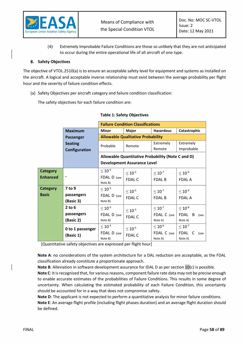
Means of Compliance with
the Special Condition VTOL
Doc. No: MOC SC-VTOL Issue: 2 Date: 12 May 2021
FINAL Page 58 of 89
Extremely Improbable Failure Conditions are those so unlikely that they are not anticipated
to occur during the entire operational life of all aircraft of one type.
Safety Objectives
The objective of VTOL.2510(a) is to ensure an acceptable safety level for equipment and systems as installed on
the aircraft. A logical and acceptable inverse relationship must exist between the average probability per flight
hour and the severity of failure condition effects.
(a) Safety Objectives per aircraft category and failure condition classification:
The safety objectives for each failure condition are:
Table 1: Safety Objectives
Failure Condition Classifications
Maximum
Passenger
Seating
Configuration
Minor Major Hazardous Catastrophic
Allowable Qualitative Probability
Probable Remote Extremely
Remote
Extremely
Improbable
Allowable Quantitative Probability (Note C and D)
Development Assurance Level
Category
Enhanced - ≤ 10-3
FDAL D (see
Note B)
≤ 10-5
FDAL C
≤ 10-7
FDAL B
≤ 10-9
FDAL A
Category
Basic
7 to 9
passengers
(Basic 3)
≤ 10-3
FDAL D (see
Note B)
≤ 10-5
FDAL C
≤ 10-7
FDAL B
≤ 10-9
FDAL A
2 to 6
passengers
(Basic 2)
≤ 10-3
FDAL D (see
Note B)
≤ 10-5
FDAL C
≤ 10-7
FDAL C (see
Note A)
≤ 10-8
FDAL B (see
Note A)
0 to 1 passenger
(Basic 1)
≤ 10-3
FDAL D (see
Note B)
≤ 10-5
FDAL C
≤ 10-6
FDAL C (see
Note A)
≤ 10-7
FDAL C (see
Note A)
[Quantitative safety objectives are expressed per flight hour]
Note A: no considerations of the system architecture for a DAL reduction are acceptable, as the FDAL
classification already constitute a proportionate approach.
Note B: Alleviation in software development assurance for IDAL D as per section 10(c) is possible.
Note C: It is recognised that, for various reasons, component failure rate data may not be precise enough
to enable accurate estimates of the probabilities of Failure Conditions. This results in some degree of
uncertainty. When calculating the estimated probability of each Failure Condition, this uncertainty
should be accounted for in a way that does not compromise safety.
Note D: The applicant is not expected to perform a quantitative analysis for minor failure conditions.
Note E: An average flight profile (including flight phases duration) and an average flight duration should
be defined.
Means of Compliance with
the Special Condition VTOL
Doc. No: MOC SC-VTOL Issue: 2 Date: 12 May 2021
FINAL Page 59 of 89
(b) Single failure and common cause failure considerations:
According to VTOL.2510(a)(1), a catastrophic failure condition must not result from the failure of a single
component, part, or element of a system. Failure containment should be provided by the system design to
limit the propagation of the effects of any single failure to preclude catastrophic failure conditions. In
addition, there must be no common-cause failure, which could affect both the single component, part, or
element, and its failure containment provisions. A single failure includes any set of failures, which cannot be
shown to be independent from each other. Common-cause failures (including common mode failures) and
cascading failures should be evaluated as dependent failures from the point of the root cause or the initiator.
Errors in development, manufacturing, installation, and maintenance can result in common-cause failures
(including common mode failures) and cascading failures. They should, therefore, be assessed and mitigated
in the frame of the common –cause and cascading failures consideration.
Protection from multiple failures should be provided when the first failure would not be detected during
normal operations of the aircraft, which includes pre-flight checks.
Sources of common cause and cascading failures include development, manufacturing, installation,
maintenance, shared resource, event outside the system(s) concerned, etc. The ARP4761 describes types of
common cause analyses, which may be conducted, to ensure that independence is maintained (e.g.
particular risk analyses, zonal safety analysis, common mode analyses), see also Section 9(b).
While single failures should normally be assumed to occur, experienced engineering judgment and relevant
service history may show that a catastrophic failure condition by a single failure mode is not a practical
possibility. The logic and rationale used in the assessment should be so straightforward and obvious that
the failure mode simply would not occur unless it is associated with an unrelated failure condition that
would, in itself, be catastrophic.
Analyses should always consider the application of the fail-safe design concept as described in section 6,
and give special attention to ensuring the effective use of design techniques that would prevent single
failures or other events from damaging or otherwise adversely affecting more than one redundant system
channel or more than one system performing operationally similar functions
Early coordination with EASA on these aspects is advised.
Safety assessment process
(a) Overview
The Safety Assessment process aims at demonstrating that systems and components are designed and installed
in a way that occurrence probabilities of failure conditions are commensurate with their classification and that
no catastrophic failure condition results from a single failure. It consists of several objectives, listed below in no
particular order:
Examine aircraft and system functions to identify potential functional failures and classify
the hazards associated with specific failure conditions.
Establish the safety requirements for the aircraft, its systems and items and validate these
safety requirements.
Verify that system architecture and design meets the corresponding safety requirements
and the safety objectives, including the single failure criterion.

Means of Compliance with
the Special Condition VTOL
Doc. No: MOC SC-VTOL Issue: 2 Date: 12 May 2021
FINAL Page 60 of 89
Establish and verify physical and functional separation, isolation and independence
requirements between systems and items, and verify that these requirements have been
met.
Guidance on how to perform the Safety Assessment process can be found in ED-79A/ARP4754A and ARP4761.
The applicant may propose other guidance for the Safety Assessment process, which should be agreed with
EASA in conjunction with the overall proposed Development Assurance process.
The depth and scope of the analyses are dependent on the system criticality and/or complexity.
The safety assessment process is an iterative process, requiring preliminary assessment steps to ensure that the
proposed system architecture(s) can reasonably be expected to meet the safety objectives, as well as regular
coordination with EASA on the different process steps.
When identifying the aircraft and system functions and classifying the hazards associated with the Failure
Conditions, the applicant will have to substantiate the effects of failure conditions with consideration to
operational conditions and events. Guidance on the handling qualities assessment can be found in MOC
VTOL.2135.
Any assumptions made during the safety assessment process need to be justified and validated.
(b) Common mode considerations
Common mode analysis (CMA) is an analytical method to define independence principles and associated
requirements, and verify that those independence requirements have been implemented sufficiently. The
CMA serves also as a tool to identify any lack of independence and to develop mitigation means to reduce
the likelihood or the effect of a common mode failure resulting from a lack of independence.
The CMA should be performed early in the safety assessment process, because it has an impact on the
definition of the safety requirements as well as on the system architecture.
Sources of common mode failures include development, manufacturing, installation, maintenance, shared
resource, event outside the system(s) concerned, etc. When identifying mitigation means for specific
common modes, the means should be appropriate to the common mode failure/error.
It is important to note that even Items that are developed to IDAL A may be subject to development error.
Such error may simultaneously affect several instances of the same item with potential functional or safety
consequences. EASA has experienced cases, where a development error in IDAL A item has even resulted in
simultaneous failures of all affected equipment. Therefore, it should not be assumed that IDAL A items are
protected from such development errors and consequently they should be included in the scope of the
common mode analysis irrespective of the FDAL/IDAL of the system/item.
The following structured approach is accepted to accomplish a common mode analysis:
Establish program-specific checklists (for common mode types, sources, and resulting
failures/errors). ARP4761 paragraph K.3.1 can be followed for this purpose. These checklists
should be used to detect elements that may defeat the redundancy or independence
principles within the design.
The following Common Modes are examples of common mode types, sources, and resulting
failures/errors to be considered:
Means of Compliance with
the Special Condition VTOL
Doc. No: MOC SC-VTOL Issue: 2 Date: 12 May 2021
FINAL Page 61 of 89
(i) Software development errors
(ii) Hardware development errors
(iii) Hardware failures
(iv) Production/repair flaws
(v) Stress related events (e.g., abnormal flight conditions, abnormal system
configurations)
(vi) Installation errors
(vii) Requirement errors
(viii) Environmental factors (e.g., temperature, vibration, humidity, etc.)
(ix) Cascading faults
(x) Common external source faults
(xi) General Common Modes are further detailed in the ARP4761 table K1.
Identify the independence principles and requirements. ARP4761 paragraph K.3.2 can be
followed for this purpose.
These Failure Conditions should cover both the availability (i.e. loss) and integrity of
functions and protections.
Analyse the design to ensure it meets the principles and requirements identified in
paragraph (2) above. ARP4761 paragraph K.3.3 can be followed for this purpose.
The analysis of the design:
(i) should be conducted not just at system level but also at item level (Airborne Electronic
Hardware items including architecture and Software items including architecture), and
(ii) should address both the availability (i.e. loss) and integrity of functions and protections.
Document the results of the above steps of the CMA process. ARP4761 paragraph K.4 can
be followed for this purpose.
Additional considerations may be appropriate for some specific systems and functions. In particular for Fly-
by-wire Flight Control Functions, MOC 4 VTOL.2300 applies.
Development Assurance process
Any analysis necessary to show compliance with VTOL.2510(a) should consider the possibility of development
errors.
For simple systems, which are not highly integrated with other aircraft systems, errors made during the
development of systems may still be detected and corrected by exhaustive tests conducted on the system and
its components, by direct inspection, and by other direct verification methods capable of completely
characterising the behaviour of the system. Such items may be considered as meeting the DAL A rigor when they
are fully assured by a combination of testing and analysis, however requirements for these items should be
validated with the rigor corresponding to the FDAL of the function. Systems which contain software and/or
complex electronic hardware items, cannot be considered simple.
For more complex or highly integrated systems, exhaustive testing may either be impossible because all of the
system states cannot be determined or impractical because of the number of tests which should be
accomplished. For these types of systems, compliance may be shown by the use of development assurance. The

Means of Compliance with
the Special Condition VTOL
Doc. No: MOC SC-VTOL Issue: 2 Date: 12 May 2021
FINAL Page 62 of 89
level of development assurance should be commensurate with the severity of the failure conditions the system
is contributing to.
(a) Development Assurance Level (DAL) allocation
The development assurance level of a function or of an item is assigned depending on the classification of
the failure conditions it contributes to.
Initial FDAL allocation is performed in accordance with Section 8(a) in this MOC.
Guidelines, which may be further used for the allocation of development assurance levels to aircraft and
system functions (FDAL) and to items (IDAL), are described in the document ED-79A/ARP4754A, section 5.2.
In the absence of agreed guidelines on FDAL/IDAL allocation, the FDAL should be commensurate with those
applicable to the category of aircraft as per Section 8(a) in this MOC and the IDAL of all components
contributing to a given function should be equal to the FDAL of that function.
(b) Aircraft/System development assurance
For the aircraft and for systems of FDAL A, B, C or D, this MOC recognises the ED-79A/ARP4754A as
acceptable guideline for establishing a development assurance process from aircraft and systems levels
down to the level where software/ Airborne Electronic Hardware (AEH) development assurance is applied.
The extent of application of ED-79A/ARP4754A to substantiate functional development assurance activities
may vary depending on the complexity of the systems and on their level of interaction with other systems.
Early concurrence with EASA is essential.
(c) Software development assurance
This MOC recognises AMC 20-115( ) as an accepted means of compliance with requirement VTOL.2510(a).
For Commercial-Off-The-Shelf (COTS) software items and open-source software, in addition to the
provisions of AMC20-115(), this MOC recognises guidance from DO-278A/ED-109A section 12.4 as an
alternative that could be generally applied beyond the limits of CNS/ATM systems. In this case, the
association between ED-12C/DO-178C software level and ED-109A/DO-278A AL (Assurance Level) can be
found in DO-278A / ED-109A table 2-2 of section 2.3.3 ‘Assurance Level Definitions’.
Alleviation for software items of IDAL D contributing to Minor Failure Conditions:
For Category Basic 1 and Basic 2 (c.f. Table 1: Safety Objectives), it is possible to alleviate
the software-level development assurance, relying on system-level development assurance
processes, provided that:
(i) the equipment is one piece of equipment; and
(ii) the equipment is developed with an acceptable development assurance process.
For Category Basic 3 (see Table 1: Safety Objectives) and Enhanced, the software-level
development assurance may be alleviated provided that:
(i) the software high-level requirements are defined and are verified to be captured in the
systems requirements as described in ED-79A/ARP4754A section 5.4; and
Means of Compliance with
the Special Condition VTOL
Doc. No: MOC SC-VTOL Issue: 2 Date: 12 May 2021
FINAL Page 63 of 89
(ii) if some are ‘derived requirements’, a mechanism is in place to properly identify, validate
and verify those derived software high-level requirements as described in ED-
79A/ARP4754A section 5.4.
Note: In both cases, the system-level processes are not considered to be software development assurance
processes.
(d) Airborne Electronic Hardware development assurance
This MOC recognises AMC 20-152( ) as accepted means of compliance for requirement VTOL.2510(a).
(e) Open Problem Report management
This MOC recognises AMC 20-189( ) as accepted means of compliance for establishing an open problem
report management process for the system, software and AEH domains.
(f) Considerations on derived requirements
ED-79A/ARP4754A section 5.3.1.4 adequately addresses the concerns related to potential for errors
introduced by derived requirements while designing and implementing the systems
However, if ED-79A/ARP4754A section 5.3.1.4 defines the derived requirements as those that “may not be
uniquely related to a higher-level requirement “, the definition could create an ambiguity as it is limited to
“Additional requirements resulting from design or implementation decisions during the development
process which are not directly traceable to higher-level requirements”.
Requirements that trace to a higher-level requirement and add a behaviour that is not specified at a higher
level should also be considered as derived.
As a consequence, the definition from ED-79A/ARP4754A is superseded by the definition provided in Section
4 of this document.
Considerations for highly integrated systems
(a) Generic guidance
When aircraft functions are provided by a combination of systems, the relevant
requirements of those systems should be validated together, including the following
activities:
(i) Analysis of the potential interactions and interferences between systems,
(ii) Planning of dedicated activities at system and aircraft levels to ensure validation of
those requirements that are affected by interactions or interference.
When incorporating multiple functions into the same system or equipment, applicability of
AMC 20-170 should be considered. For architectures with no partitioning, particular care
should be taken in the analysis of interactions between functions.
(b) Additional Considerations for the Lift/Thrust system
For most VTOL aircraft designs, the Flight Control System and the Lift/Thrust system are highly integrated,
i.e. the propulsion system directly contributes to the controllability of the aircraft. Therefore the
development of the Lift/Thrust system should take into consideration the safety objectives of Section 8 and
should follow the provisions of VTOL.2510 and associated guidance.

Means of Compliance with
the Special Condition VTOL
Doc. No: MOC SC-VTOL Issue: 2 Date: 12 May 2021
FINAL Page 64 of 89
Latent failure considerations
The use of periodic maintenance or flight crew checks to detect significant latent failures when they occur is
undesirable and should not be used in lieu of practical and reliable failure monitoring and indications. Significant
latent failures are latent failures that would, in combination with one or more specific failure(s) or event(s),
result in a Hazardous or Catastrophic failure condition and should be avoided in system design.
Within the frame of the no single failure criterion, dual failure combinations, with either one latent, that can
lead to a Catastrophic Failure Condition should be avoided in system design. Any such combinations should be
highlighted in the relevant SSA and discussed with EASA as early as possible after identification.
Additional considerations may be appropriate for some specific systems and functions. In particular for Fly-by-
wire Flight Control Functions, MOC 5 VTOL.2300 applies.
Flight Crew and Maintenance considerations
(a) Flight Crew actions
When assessing the ability of the flight crew to cope with a failure condition, the information that is provided
to the flight crew and the complexity of the required action should be considered. If the evaluation indicates
that a potential failure condition can be alleviated or overcome during the time available without
jeopardizing other safety related flight crew tasks and without requiring exceptional pilot skill or strength,
credit may be taken for correct and appropriate corrective action for both qualitative and quantitative
assessments. Similarly, credit may be taken for correct flight crew performance if overall flight crew
workload during the time available is not excessive and if the tasks do not require exceptional pilot skill or
strength. Unless flight crew actions are accepted as normal airmanship, the appropriate procedures should
be included in the EASA-approved AFM or in the AFM revision or supplement. The AFM should include
procedures for operation of complex systems such as integrated flight guidance and control systems. These
procedures should include proper pilot response to cockpit indications, diagnosis of system failures,
discussion of possible pilot-induced flight control system problems, and use of the system in a safe manner.
(b) Maintenance actions
Credit may be taken for the correct accomplishment of maintenance tasks in both qualitative and
quantitative assessments if the tasks are evaluated and found to be reasonable. Required maintenance
tasks, which mitigate hazards, should be provided for use in EASA-approved ICA. Annunciated failures that
will be corrected before the next flight or a maximum duration should be established before a maintenance
action is required. If the latter is acceptable, the analysis should establish the maximum allowable interval
before the maintenance action is required. A scheduled maintenance task may detect latent failures. If this
approach is taken, and the failure condition is hazardous or catastrophic, then a maintenance task should
be established. The process for the identification and selection of these scheduled maintenance tasks
requires early coordination and agreement with EASA. Guidance may be found in AMC 25-19.
Credit could be given to tests performed due to mean time between failures (MTBF) to detect the presence
of hidden failures, if it can be ascertained that the equipment is removed and inspected at a rate much more
frequent than the safety analysis requires. This credit should be substantiated in the relevant SSA. The
means of detection of the hidden failures should be clearly identified, either at the opportunity of the
acceptance tests performed before the equipment enters service or leaves the manufacturer, or at the
opportunity of test of system integrity when it is installed back on the aircraft. This substantiation should be
Means of Compliance with
the Special Condition VTOL
Doc. No: MOC SC-VTOL Issue: 2 Date: 12 May 2021
FINAL Page 65 of 89
recorded in the relevant SSA. In case of double failures, with either one or both hidden, that can lead to
Catastrophic or Hazardous Failure Condition, no credit should be taken from MTBF for failure detection, and
the maintenance task enabling detection of the hidden failure should be identified as a required
maintenance task.
MOC VTOL.2515 Electrical and electronic system lightning protection
Unlikely Exposure to Lightning
It is stated in VTOL.2515 that sub paragraphs (a) and (b) are applicable “unless it is shown that the exposure to
lightning is unlikely”. The demonstration on this condition should be based on reliable meteorological reports
and/or on-board means to detect lightning, directly or indirectly (e.g. Lightning Detector, Weather Radar).
Therefore, an accepted means to avoid the compliance demonstration with electrical and electronic system
lightning protection requirements is to establish the following operational limitations:
(a) VFR Day with reliable weather reports stating the absence of significant clouds before and/or during the
flight for departure, enroute, terminal and diversion vertiports, or
(b) VFR with means to detect lightning or storm cells via a certified onboard system, and/or ground base
support plus appropriate communication with the pilot. The qualification of such ground-based system
should be ensured by the operator.
When VTOL.2515 (a) and (b) are applicable, this MOC proposes simplified methods for addressing the Indirect
Effects of Lightning (IEL) compliance demonstration on VTOL aircraft. These methods vary depending on the
VTOL Aircraft categories; Basic 1 (0 to 1 passenger), Basic 2 (2 to 6 passengers), Basic 3 (7 to 9 passengers) and
Enhanced.
Reference Documents
The following references are quoted in different sections of this MOC as a source of additional information
or to provide accepted methods and practices:
(a) Industry Standards
ASTM
F3061/F3061M Specification for Systems and Equipment in Small Aircraft
F3230 Standard Practice for Safety Assessment of Systems and Equipment in Small Aircraft
F3309 Standard Practice for Simplified Safety Assessment of Systems and Equipment in Small Aircraft
EUROCAE/SAE/RTCA
ED-81/ARP5413A Certification of an Aircraft Electrical/Electronic Systems for the Indirect Effect of Lightning
ED-84/ARP5412B Aircraft Lightning Environment and Related Test Waveforms
ED-91/ARP5414B Aircraft Lightning Zoning ED-105/ARP5416A Aircraft Lightning Test Methods

Means of Compliance with
the Special Condition VTOL
Doc. No: MOC SC-VTOL Issue: 2 Date: 12 May 2021
FINAL Page 66 of 89
ED-158/ARP5415B User/s Manual for Certification of Aircraft Electrical/Electronic Systems for the Indirect Effect of Lightning
ED-14()/DO-160() Environmental Conditions and Test Procedures for Airborne Equipment
(b) Authorities Guidance
FAA
PS-ACE-23-10 HIRF/Lightning Test Levels and Compliance Methods for 14 CFR Part 23 Class I, II, and III Aircraft Note: only partially recognised by EASA
AC 23.1309-1E System Safety Analysis and Assessment for Part 23 Aircraft
AC 20-136B The Certification of Aircraft Electrical and Electronic Systems for Operation in the High-intensity Radiated Fields (HIRF) Environment
EASA
MOC VTOL.2515 Acceptable Means of Compliance for VTOL System Safety Analysis and Assessment
AMC 20-136 Aircraft Electrical and Electronic System Lightning Protection
Definitions
For the purpose of this MOC the following definitions apply:
(a) Actual Transient Level (ATL): The level of transient voltage or current that appears at the equipment
interface circuits due to the external environment. This level may be less than or equal to the transient
control level, but should not be greater.
(b) Adverse Effect: A response of a system that results in an undesirable and/or unexpected operation of
an aircraft system, or undesirable and/or unexpected operation of the function performed by the
system.
(c) Ceiling And Visibility are OK (CAVOK): statement in meteorological report indicating that there are no
clouds below 5000 ft AGL (or Minimum Sector Altitude whichever is greater), no presence of Towering
Cumulus (TCU) and/or Cumulonimbus (CB) and visibility above 10 km.
(d) Equipment: A component of an electrical or electronic system with interconnecting electrical
conductors.
(e) Equipment Transient Design Level (ETDL): The peak amplitude of transients to which equipment is
qualified.
(f) Hazard related to lightning exposure: Comparison between the probability to be struck by Lightning
and the failure from another internal cause.
(g) IEL Group: Group of VTOL categories having the same methodology for their Indirect Effects of Lightning
compliance demonstration. 3 Groups have been identified; Group I for VTOL Category “Basic 1” (0-1
passenger), Group II for VTOL Category “Basic 2” (2-6 passengers) and Group III for VTOL Categories
“Basic 3” (7-9 passengers) and Enhanced.
(h) Immunity: Capacity of a system or piece of equipment to continue to perform its intended function, in
an acceptable manner, in the presence of an electrical transient.
(i) Indirect effects: Electrical transients induced by lightning in aircraft electrical or electronic circuits.

Means of Compliance with
the Special Condition VTOL
Doc. No: MOC SC-VTOL Issue: 2 Date: 12 May 2021
FINAL Page 67 of 89
(j) Internal environment: The potential fields and structural voltages inside the aircraft that are produced
by the external environment.
(k) Lightning Certification Level (LCL): Level of an electrical or electronic system performing a function
whose most critical Failure Condition is catastrophic, hazardous or major.
(l) Margin: The difference between the equipment transient design levels and the actual transient level.
(m) No Significant Cloud (NSC): statement where CAVOK information is not met but ensures no presence of
Towering Cumulus (TCU) and/or Cumulonimbus (CB).
(n) Normal Operation: A status where the system is performing its intended function. When addressing
compliance with VTOL.2515 (a) (2), the function whose failure would prevent the continued safe flight
and landing for Category Enhanced or a controlled emergency landing for Category Basic should be in
the same undisturbed state than before exposure to the Lightning threat. Other functions, performed
by the same system, subject to VTOL.2515 (b), are not required to be recovered.
(o) System: An electrical or electronic system includes all electrical and electronic equipment, components
and electrical interconnections that are required to perform a particular function.
(p) Transient Control Level (TCL): The maximum allowable level of transients that appear at the equipment
interface circuits because of the defined external environment.
(q) Upset: Impairment of system operation, either permanent or momentary. For example, a change of
digital or analogue state that may or may not require a manual reset.
Means of Compliance:
(a) Minimum Design Considerations
In order to utilise the methods described in this practice, the following minimum design
considerations should be addressed. If deviations from these minimum design
considerations are desired, the acceptability of the methods described should be agreed by
EASA.
The airframe should incorporate low impedance electrical conductors to allow lightning
current to flow through the aircraft. The low impedance conductors should be incorporated
into the basic structure of the aircraft.
(i) For aircraft with primarily metal structure, the metal skin provides a low impedance
electrical conductor. Standard rivets and bolts should provide adequate electrical
bonding between permanent structural joints. Electrical bonding straps or jumpers
should be installed on moving parts or for removable panels or parts.
(ii) For aircraft with primarily carbon fibre or fiberglass structure, metal mesh, metal foil,
or expanded metal foil should be incorporated onto the external surfaces of the aircraft
composite structure. This mesh or foil should be joined together electrically and provide
a continuous electrical conductor between the extremities of the aircraft. Metallic
components that are internal to the structure of the aircraft may also be used to provide
similar shielding for equipment and its wiring.
(iii) For aircraft constructed of tube and fabric, the tube skeleton can be considered to be
the low impedance electrical path through the aircraft. The bonding also may be
achieved by the use of bonding straps or jumpers where required to electrically bond
other metallic sub-structure that might be relied upon to provide bonding for
equipment.
Electrical bonding specifications and verifications should be developed and implemented on
the production drawings and instructions for continued airworthiness.
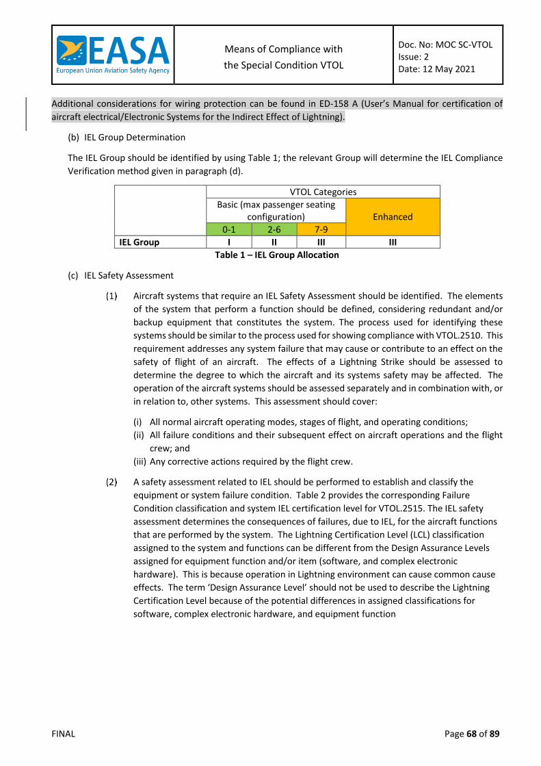
Means of Compliance with
the Special Condition VTOL
Doc. No: MOC SC-VTOL Issue: 2 Date: 12 May 2021
FINAL Page 68 of 89
Additional considerations for wiring protection can be found in ED-158 A (User’s Manual for certification of
aircraft electrical/Electronic Systems for the Indirect Effect of Lightning).
(b) IEL Group Determination
The IEL Group should be identified by using Table 1; the relevant Group will determine the IEL Compliance
Verification method given in paragraph (d).
VTOL Categories
Basic (max passenger seating configuration)
Enhanced
0-1 2-6 7-9
IEL Group I II III III
Table 1 – IEL Group Allocation
(c) IEL Safety Assessment
Aircraft systems that require an IEL Safety Assessment should be identified. The elements
of the system that perform a function should be defined, considering redundant and/or
backup equipment that constitutes the system. The process used for identifying these
systems should be similar to the process used for showing compliance with VTOL.2510. This
requirement addresses any system failure that may cause or contribute to an effect on the
safety of flight of an aircraft. The effects of a Lightning Strike should be assessed to
determine the degree to which the aircraft and its systems safety may be affected. The
operation of the aircraft systems should be assessed separately and in combination with, or
in relation to, other systems. This assessment should cover:
(i) All normal aircraft operating modes, stages of flight, and operating conditions;
(ii) All failure conditions and their subsequent effect on aircraft operations and the flight
crew; and
(iii) Any corrective actions required by the flight crew.
A safety assessment related to IEL should be performed to establish and classify the
equipment or system failure condition. Table 2 provides the corresponding Failure
Condition classification and system IEL certification level for VTOL.2515. The IEL safety
assessment determines the consequences of failures, due to IEL, for the aircraft functions
that are performed by the system. The Lightning Certification Level (LCL) classification
assigned to the system and functions can be different from the Design Assurance Levels
assigned for equipment function and/or item (software, and complex electronic
hardware). This is because operation in Lightning environment can cause common cause
effects. The term ‘Design Assurance Level’ should not be used to describe the Lightning
Certification Level because of the potential differences in assigned classifications for
software, complex electronic hardware, and equipment function
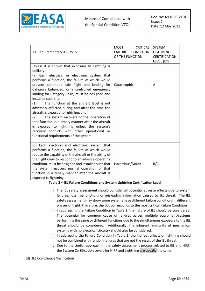
Means of Compliance with
the Special Condition VTOL
Doc. No: MOC SC-VTOL Issue: 2 Date: 12 May 2021
FINAL Page 69 of 89
IEL Requirements VTOL.2515
MOST CRITICAL FAILURE CONDITION OF THE FUNCTION
SYSTEM LIGHTNING CERTIFICATION LEVEL (LCL)
Unless it is shown that exposure to lightning is unlikely: (a) Each electrical or electronic system that performs a function, the failure of which would prevent continued safe flight and landing for Category Enhanced, or a controlled emergency landing for Category Basic, must be designed and installed such that: (1) The function at the aircraft level is not adversely affected during and after the time the aircraft is exposed to lightning; and (2) The system recovers normal operation of that function in a timely manner after the aircraft is exposed to lightning unless the system’s recovery conflicts with other operational or functional requirements of the system.
Catastrophic
A
(b) Each electrical and electronic system that performs a function, the failure of which would reduce the capability of the aircraft or the ability of the flight crew to respond to an adverse operating condition, must be designed and installed such that the system recovers normal operation of that function in a timely manner after the aircraft is exposed to lightning.
Hazardous/Major
B/C
Table 2 – IEL Failure Conditions and System Lightning Certification Level
(i) The IEL safety assessment should consider all potential adverse effects due to system
failures; loss, malfunctions or misleading information caused by IEL threat. The IEL
safety assessment may show some systems have different failure conditions in different
phases of flight; therefore, the LCL corresponds to the most critical Failure Condition
(ii) In addressing the Failure Condition in Table 2, the nature of IEL should be considered.
The potential for common cause of failures across multiple equipment/systems
performing the same or different functions due to the simultaneous exposure to the IEL
threat should be considered. Additionally, the inherent immunity of mechanical
systems with no electrical circuitry should also be considered.
(iii) In addressing the Failure Condition in Table 2, the indirect effects of lightning should
not be combined with random failures that are not the result of the IEL threat.
(iv) Due to the similar approach in the safety assessment process related to IEL and HIRF,
the System Certification Levels for HIRF and Lightning are usually the same.
(d) IEL Compliance Verification

Means of Compliance with
the Special Condition VTOL
Doc. No: MOC SC-VTOL Issue: 2 Date: 12 May 2021
FINAL Page 70 of 89
Unless operational limitations are implemented to only allow operation in VFR Day with
reliable weather reports on the absence of significant clouds, or the Operation in VFR is
permitted with certified VTOL systems to detect the lightning strike or storm cells, then the
likelihood of exposure to lightning in VMC condition has to be considered (see Figures 1 and
2 in Section 5). Nevertheless, the Hazard related to this exposure on VTOL aircraft could be
assessed by comparing the Rate of lightning strike to Aircraft and the Safety objectives at
Aircraft Level (see Table 3 in Section 5); in some cases, the probability of having a lightning
strike to an aircraft is lower than the probability of having a failure from another technical
cause. In such cases, the Hazard associated with a lightning strike can be considered to be
unlikely and therefore for lower IEL Groups and the IEL Groups operating in VFR, VTOL.2515
(b) is not applicable for Level B and/or C systems that can be removed from the verification
(see Section 6).
IEL Group I
(i) For level A Systems (Display and Non-Display)
(A) Follow the AMC 20-136; or
(B) Conduct Equipment/System testing using the following categories:
According to the VTOL aircraft primary structure and wiring type,
choose the appropriate Category/Waveform at Level 3 in EUROCAE ED-
14G section 22.
Fail/Pass Criteria: when subjected to the Lightning Environment, it
could be acceptable that equipment is/are subject to adverse effect,
provided that the Level A function is maintained at the aircraft level and
all the Equipment/Systems that are required in normal operation
recover manually or automatically, in a timely manner, this function
after the threat.
(ii) For Level B Systems on aircraft approved for IFR Operation
Conduct Equipment/System testing using the following categories:
(A) According to the VTOL aircraft primary structure and wiring type, choose the
appropriate Category/Waveform at Level 2 in EUROCAE ED-14G 22.
(B) Fail/Pass Criteria; when submitted to the Lightning Environment, it could be
acceptable that redundant equipment is/are subject to adverse effect, provided that
the Level B function is recovered manually or automatically, in a timely manner, after
the threat.
IEL Group II
(i) For level A Systems (Display and Non-Display)
(A) Follow the AMC 20-136; or
(B) Conduct Equipment/System testing using the following categories:
According to the VTOL aircraft primary structure and wiring type,
choose the appropriate Category/Waveform at Level 3 in EUROCAE ED-
14G section 22.

Means of Compliance with
the Special Condition VTOL
Doc. No: MOC SC-VTOL Issue: 2 Date: 12 May 2021
FINAL Page 71 of 89
Fail/Pass Criteria; when submitted to the Lightning Environment, it
could be acceptable that equipment is/are subject to adverse effect;
provided that the Level A function is maintained at the aircraft level and
all the Equipment/System, required in normal operation, recover
manually or automatically, in a timely manner, this function after the
threat.
(ii) For Level B Systems
Conduct Equipment/System testing using the following categories:
(A) According to the VTOL aircraft primary structure and wiring type, choose the
appropriate Category/Waveform at Level 2 in EUROCAE ED-14G 22.
(B) Fail/Pass Criteria; when submitted to the Lightning Environment, it could be
acceptable that redundant equipment is/are subject to adverse effects, provided
that the Level B function is recovered manually or automatically, in a timely manner,
after the threat.
IEL Group III
(i) For Level A Non-Display Systems:
(A) Follow the AMC 20-136; or
(B) Determine the aircraft Actual Transient Level (ATL) (by test, analysis, combination of
both or by similarity); and
(C) Conduct Equipment/System testing using the following categories:
According to the VTOL aircraft primary structure and wiring type,
choose the appropriate Category/Waveform at Level 3 or 4 in EUROCAE
ED-14G section 22.
Fail/Pass Criteria; when submitted to the Lightning Environment, it
could be acceptable that equipment is/are subject to adverse effect,
provided that the Level A function is maintained at the aircraft level and
all the Equipment/Systems that are required in normal operation,
recover manually or automatically, in a timely manner, this function
after the threat.
Verify the positive margin between the default levels applied during the
Equipment/System testing (EDTL as defined in (a)) and the Transient
Control Level (TCL, maximum expected aircraft ATLs). If a positive
margin is not established, corrective measures should be implemented
in line with AMC 20-136.
(ii) For level A Display Systems:
Conduct Equipment/System testing using the following categories:
(A) For VTOL aircraft with primarily metal structure, EUROCAE ED-14G section 22
category A3J3L3.
(B) For VTOL aircraft with primarily carbon fibre, fiberglass or non-conductive material
structure, EUROCAE ED-14G section 22 category B3K3L3.
Means of Compliance with
the Special Condition VTOL
Doc. No: MOC SC-VTOL Issue: 2 Date: 12 May 2021
FINAL Page 72 of 89
(C) Fail/Pass Criteria; when submitted to the Lightning Environment, it could be
acceptable that equipment is/are subject to adverse effect, provided that the Level
A function is maintained at the aircraft level and all the Equipment/Systems required
in normal operation recover manually or automatically, in a timely manner, this
function after the threat.
(iii) For level B Systems:
Conduct Equipment/System testing using the following categories:
(A) For VTOL aircraft with primarily metal structure, EUROCAE ED-14G 22 category
A2J2L2.
(B) For VTOL aircraft with primarily carbon fibre, fiberglass or non-conductive material
structure, EUROCAE ED-14G section 22 category B2K2L2.
(C) Fail/Pass Criteria; when submitted to the Lightning Environment, it could be
acceptable if redundant equipment is/are subject to adverse effect, provided that
the Level B function is recovered manually or automatically, in a timely manner, after
the threat.
(iv) For Level C Systems on aircraft approved for IFR Operation:
Conduct Equipment/System testing using the following categories:
(A) For VTOL aircraft with primarily metal structure, EUROCAE ED-14G 22 category
A1J1L1.
(B) For VTOL aircraft with primarily carbon fibre, fiberglass or non-conductive material
structure, EUROCAE ED-14G section 22 category B1K1L1.
(C) Fail/Pass Criteria; when submitted to the Lightning Environment, it could be
acceptable that redundant equipment is/are subject to adverse effect, provided that
the Level C function is recovered manually or automatically, in a timely manner, after
the threat.
IEL Testing for Level A Systems considerations;
(i) The Test Levels for upper IEL Group could also be used for lower IEL Group; for instance,
the use of the level for Level A Non-Display System for IEL Group III can be used for Level
A System of IEL Groups I/II.
(ii) Equipment testing is acceptable when it is shown that the interdependencies between
equipment performing a function are understood and each equipment is tested and
monitored to verify there is no unacceptable upset of the function. (iii) If similar equipment are used to perform the same function, the test can be limited to
a single equipment.
Level A System architecture consideration: when a level A system is composed of redundant
channels/equipment that perform the same level A function, it is permitted to limit the
system to the channels/equipment that are required in normal operation provided that they
are not susceptible when they comply with VTOL.2515(a); for instance if it is demonstrated
that the primary channels comply with VTOL.2515(a) without the support of the back-up
channel, the equipment of this channel is/are not required to be qualified to Level 3/4,
however this back-up channel should be considered to be as a level B system (Level 2).
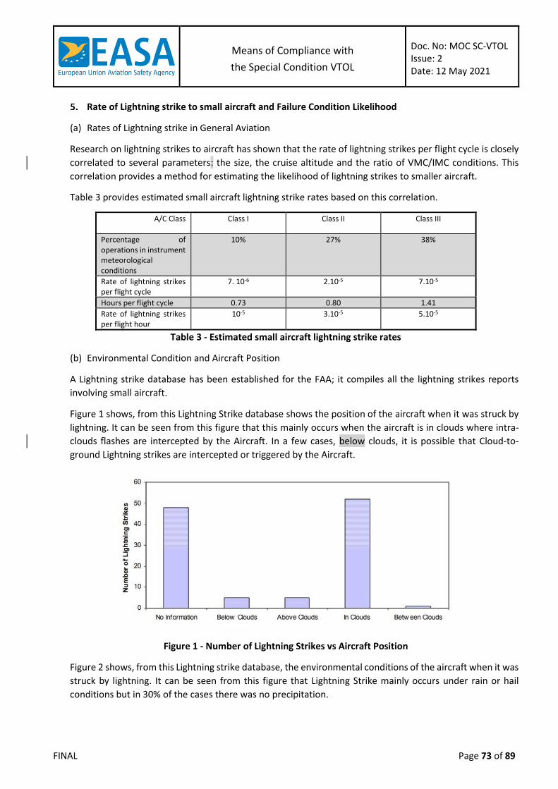
Means of Compliance with
the Special Condition VTOL
Doc. No: MOC SC-VTOL Issue: 2 Date: 12 May 2021
FINAL Page 73 of 89
Rate of Lightning strike to small aircraft and Failure Condition Likelihood
(a) Rates of Lightning strike in General Aviation
Research on lightning strikes to aircraft has shown that the rate of lightning strikes per flight cycle is closely
correlated to several parameters: the size, the cruise altitude and the ratio of VMC/IMC conditions. This
correlation provides a method for estimating the likelihood of lightning strikes to smaller aircraft.
Table 3 provides estimated small aircraft lightning strike rates based on this correlation.
A/C Class Class I Class II Class III
Percentage of operations in instrument meteorological conditions
10% 27% 38%
Rate of lightning strikes per flight cycle
7. 10-6 2.10-5 7.10-5
Hours per flight cycle 0.73 0.80 1.41
Rate of lightning strikes per flight hour
10-5 3.10-5 5.10-5
Table 3 - Estimated small aircraft lightning strike rates
(b) Environmental Condition and Aircraft Position
A Lightning strike database has been established for the FAA; it compiles all the lightning strikes reports
involving small aircraft.
Figure 1 shows, from this Lightning Strike database shows the position of the aircraft when it was struck by
lightning. It can be seen from this figure that this mainly occurs when the aircraft is in clouds where intra-
clouds flashes are intercepted by the Aircraft. In a few cases, below clouds, it is possible that Cloud-to-
ground Lightning strikes are intercepted or triggered by the Aircraft.
Figure 1 - Number of Lightning Strikes vs Aircraft Position
Figure 2 shows, from this Lightning strike database, the environmental conditions of the aircraft when it was
struck by lightning. It can be seen from this figure that Lightning Strike mainly occurs under rain or hail
conditions but in 30% of the cases there was no precipitation.
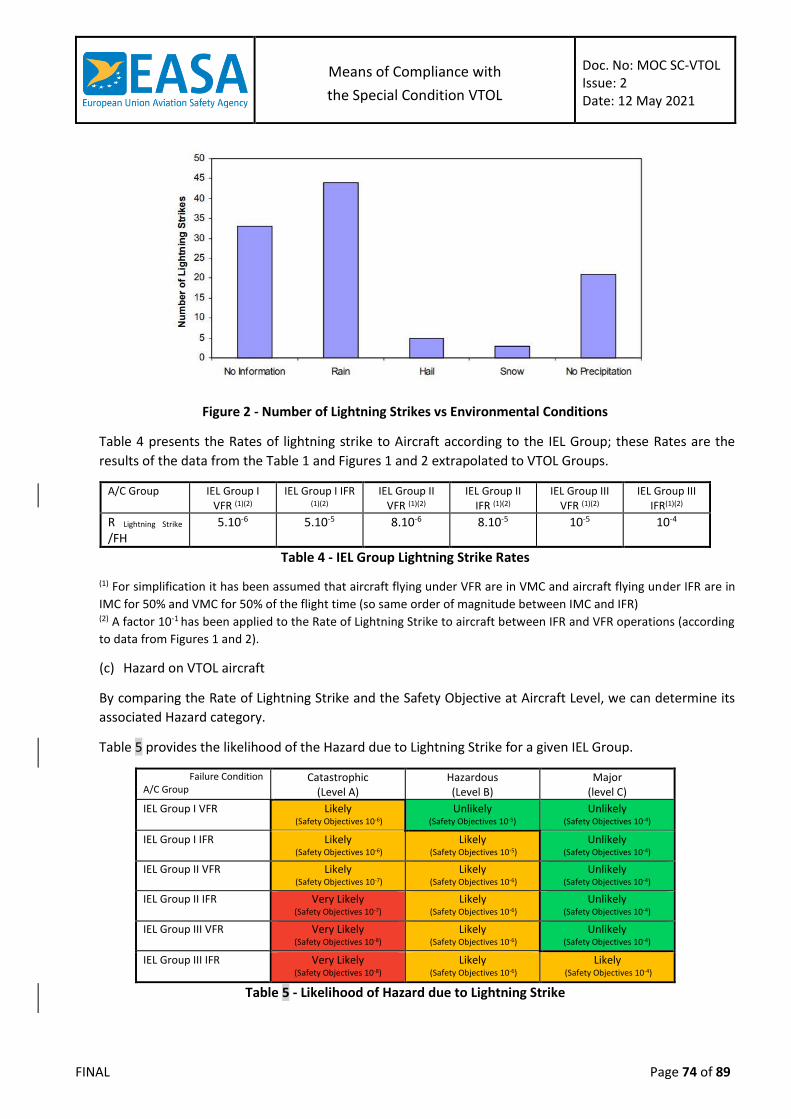
Means of Compliance with
the Special Condition VTOL
Doc. No: MOC SC-VTOL Issue: 2 Date: 12 May 2021
FINAL Page 74 of 89
Figure 2 - Number of Lightning Strikes vs Environmental Conditions
Table 4 presents the Rates of lightning strike to Aircraft according to the IEL Group; these Rates are the
results of the data from the Table 1 and Figures 1 and 2 extrapolated to VTOL Groups.
A/C Group IEL Group I VFR (1)(2)
IEL Group I IFR (1)(2)
IEL Group II VFR (1)(2)
IEL Group II IFR (1)(2)
IEL Group III VFR (1)(2)
IEL Group III IFR(1)(2)
R Lightning Strike
/FH 5.10-6 5.10-5 8.10-6 8.10-5 10-5 10-4
Table 4 - IEL Group Lightning Strike Rates
(1) For simplification it has been assumed that aircraft flying under VFR are in VMC and aircraft flying under IFR are in
IMC for 50% and VMC for 50% of the flight time (so same order of magnitude between IMC and IFR) (2) A factor 10-1 has been applied to the Rate of Lightning Strike to aircraft between IFR and VFR operations (according
to data from Figures 1 and 2).
(c) Hazard on VTOL aircraft
By comparing the Rate of Lightning Strike and the Safety Objective at Aircraft Level, we can determine its
associated Hazard category.
Table 5 provides the likelihood of the Hazard due to Lightning Strike for a given IEL Group.
Failure Condition A/C Group
Catastrophic (Level A)
Hazardous (Level B)
Major (level C)
IEL Group I VFR Likely (Safety Objectives 10-6)
Unlikely (Safety Objectives 10-5)
Unlikely (Safety Objectives 10-4)
IEL Group I IFR Likely (Safety Objectives 10-6)
Likely (Safety Objectives 10-5)
Unlikely (Safety Objectives 10-4)
IEL Group II VFR Likely (Safety Objectives 10-7)
Likely (Safety Objectives 10-6)
Unlikely (Safety Objectives 10-4)
IEL Group II IFR
Very Likely (Safety Objectives 10-7)
Likely (Safety Objectives 10-6)
Unlikely (Safety Objectives 10-4)
IEL Group III VFR Very Likely (Safety Objectives 10-8)
Likely (Safety Objectives 10-6)
Unlikely (Safety Objectives 10-4)
IEL Group III IFR Very Likely (Safety Objectives 10-8)
Likely (Safety Objectives 10-6)
Likely (Safety Objectives 10-4)
Table 5 - Likelihood of Hazard due to Lightning Strike

Means of Compliance with
the Special Condition VTOL
Doc. No: MOC SC-VTOL Issue: 2 Date: 12 May 2021
FINAL Page 75 of 89
P Hazard = R Lightning Strike / S Safety Objective
P Hazard < 1: Hazard is Unlikely, 1 ≤ P Hazard ≤ 102: Hazard is Likely, P Risk > 102: Hazard is Very Likely
Decisional Flow Chart on the Hazard related to Lightning Exposure to Aircraft
MOC VTOL.2520 High-intensity radiated fields (HIRF) protection
Scope of this MOC
This MOC proposes simplified methods for addressing High Intensity Radiated Fields (HIRF) compliance
demonstration on VTOL aircraft. These methods depend on the VTOL Aircraft Category; Basic 0 to 1 passenger,
Basic 2 to 6 passengers, Basic 7 to 9 passengers and Enhanced.
The topics covered within this MOC are: Minimum Design Requirements, HIRF Group Determination, HIRF Safety
Assessment and HIRF Compliance Verification.
Operational Limitations
Yes
No
Level C System ?
Yes
Level B System ?
No IEL Group I
VFR?
Yes
IEL Group III IFR?
No
Yes
No
No
Yes
Lightning Exposure
It is a Level A System
Hazard related to lightning is Likely – Assessment requested For Level A System, Level B System (Except IEL Group I VFR) and Level C for
IEL Group III IFR
No Hazard related to lightning – No assessment needed For all Systems on VTOL Aircraft A/C flying with CAVOK/NSC conditions
or For Level C System (Except IEL Group III IFR) and Level B System for IEL
Group I VFR
IEL Safety Assessment (Level A/B/C Systems)

Means of Compliance with
the Special Condition VTOL
Doc. No: MOC SC-VTOL Issue: 2 Date: 12 May 2021
FINAL Page 76 of 89
Reference Documents
The following references are quoted in different sections of this MOC as a source of additional information or
to provide accepted methods and practices:
(a) Industry Standards
ASTM
F3061/F3061M Specification for Systems and Equipment in Small Aircraft
F3230 Standard Practice for Safety Assessment of Systems and Equipment in Small Aircraft
F3309 Standard Practice for Simplified Safety Assessment of Systems and Equipment in Small Aircraft
EUROCAE/SAE/RTCA
ED-107A/ARP 5583A
Guide to Certification of Aircraft in a High Intensity Radiated Field (HIRF) Environment
ED-14()/DO-160()
Environmental Conditions and Test Procedures for Airborne Equipment
(b) Authorities Guidance
FAA
PS-ACE-23-10 HIRF/Lightning Test Levels and Compliance Methods for 14 CFR Part 23 Class I, II, and III Airplanes Note: only partially recognised by EASA
AC 23.1309-1E System Safety Analysis and Assessment for Part 23 Airplanes
AC 20-158A The Certification of Aircraft Electrical and Electronic Systems for Operation in the High-intensity Radiated Fields (HIRF) Environment
EASA
MOC VTOL.2510 Means of Compliance for VTOL Equipment Systems and installations
AMC 20-158 Aircraft Electrical and Electronic System High-intensity Radiated Fields (HIRF) Protection
Definitions
For the purpose of this MOC the following definitions apply:
(a) Adverse Effect: A response of a system that results in an undesirable and/or unexpected operation of
an aircraft system, or undesirable and/or unexpected operation of the function performed by the
system.
(b) Attenuation: Term used to denote a decrease in electromagnetic field strength in transmission from one
point to another. Attenuation may be expressed as a scalar ratio of the input magnitude to the output
magnitude or in decibels (dB).

Means of Compliance with
the Special Condition VTOL
Doc. No: MOC SC-VTOL Issue: 2 Date: 12 May 2021
FINAL Page 77 of 89
(c) Equipment: Component of an electrical or electronic system with interconnecting electrical conductors.
(d) External High-intensity Radiated Fields Environment: Electromagnetic RF fields at the exterior of an
aircraft.
(e) Field Strength: Magnitude of the electromagnetic energy propagating in free space expressed in volts
per meter (V/m).
(f) High-intensity Radiated Fields (HIRF) Environment: Electromagnetic environment that exists from the
transmission of high power RF energy into free space.
(g) High-intensity Radiated Fields (HIRF) Test level: The level of Field Strength applied during the
Equipment/System Test, it may vary according the RF Band.
(h) HIRF Certification Level (HCL): The level of an electrical or electronic system that performs a function
whose worst Failure Condition classification is catastrophic, hazardous or major.
(i) HIRF Group: Group of VTOL categories having the same methodology for their HIRF compliance
demonstration. 3 Groups have been identified; Group I for VTOL Category “Basic 1” (0-1 passenger),
Group II for VTOL Category “Basic 2” (2-6 passengers) and Group III for VTOL Categories “Basic 3” (7-9
passengers) and Enhanced.
(j) Immunity: The capacity of a system or piece of equipment to continue to perform its intended function,
in an acceptable manner, in the presence of RF fields.
(k) Internal HIRF Environment: RF environment inside an airframe, equipment enclosure, or cavity. The
internal RF environment is described in terms of the internal RF field strength or wire bundle current.
(l) Normal Operation: A state of the system where the system is performing its intended function. When
addressing compliance with VTOL.2520 (a) (2), the function whose failure would prevent the continued
safe flight and landing for Category Enhanced or a controlled emergency landing for Category Basic
should be in the same undisturbed state than before exposure to the HIRF threat. Other functions,
performed by the same system, subject to VTOL.2520 (b), are not required to be recovered.
(m) Radio Frequency (RF): Frequency useful for radio transmission. The present practical limits of RF
transmissions are roughly 10 kilohertz (kHz) to 100 gigahertz (GHz). Within this frequency range,
electromagnetic energy may be detected and amplified as an electric current at the wave frequency.
(n) System: The piece of equipment connected via electrical conductors to another piece of equipment,
both of which are required to make a system function. A system may contain pieces of equipment,
components, parts, and wire bundles.
(o) Transfer Function: The ratio of the electrical output of a system to the electrical input of a system,
expressed in the frequency domain. For HIRF, a typical transfer function is the ratio of the current on a
wire bundle to the external HIRF field strength, as a function of frequency.
(p) Upset: An impairment of system operation, either permanent or momentary. For example, a change of
digital or analogue state that may or may not require a manual reset.
Means of Compliance
(a) Minimum Design Considerations
In order to utilise the methods described in this practice, the following minimum design
considerations should be addressed. If deviations from these minimum design
considerations are desired, the acceptability of the methods described should be agreed to
by EASA.
The airframe should incorporate low impedance electrical conductors to allow induced
current to flow through the aircraft. The low impedance conductors should be incorporated
into the basic structure of the aircraft.

Means of Compliance with
the Special Condition VTOL
Doc. No: MOC SC-VTOL Issue: 2 Date: 12 May 2021
FINAL Page 78 of 89
(i) For aircraft with primarily metal structure, the metal skin provides a low impedance
electrical conductor. Standard rivets and bolts should provide adequate electrical
bonding between permanent structural joints. Electrical bonding straps or jumpers
should be installed on moving parts or for removable panels or parts.
(ii) For aircraft with primarily carbon fibre or fiberglass structure, metal mesh, metal foil,
or expanded metal foil should be incorporated onto the external surfaces of the aircraft
composite structure. This mesh or foil should be joined together electrically and provide
a continuous electrical conductor between the extremities of the aircraft. Metallic
components that are internal to the structure of the aircraft may also be used to provide
similar shielding for equipment and its wiring.
(iii) For aircraft constructed of tube and fabric, the tube skeleton can be considered to be
the low impedance electrical path through the aircraft. The bonding also may be
achieved by the use of bonding straps or jumpers where required to electrically bond
other metallic sub-structure that might be relied upon to provide bonding for
equipment.
Electrical bonding specifications and verifications should be developed and implemented on
the production drawings and instructions for continued airworthiness.
(b) HIRF Group Determination
The HIRF Group should be identified by using Table 1; the relevant Group will determine the HIRF
Compliance Verification method given in paragraph (d).
VTOL Categories
Basic (max passenger seating configuration)
Enhanced
0-1 2-6 7-9
HIRF Group I II III III
Table 1 – HIRF Group Allocation
(c) HIRF Safety Assessment
The VTOL aircraft systems that require a HIRF Safety Assessment should be identified. The
elements of the system that perform a function should be defined, considering the use of
redundant and/or backup equipment that constitutes the system. The process used for
identifying these systems should be similar to the process used for showing compliance with
VTOL.2510. This requirement addresses any system failure that may cause or contribute to
an effect on the safety of flight of a VTOL aircraft. The effects of a HIRF encounter should
be assessed to determine the degree to which the aircraft and its systems safety may be
affected. The operation of the aircraft systems should be assessed separately and in
combination with, or in relation to, other systems. This assessment should cover:
(i) All normal VTOL aircraft operating modes, stages of flight, and operating conditions;
(ii) All failure conditions and their subsequent effect on VTOL aircraft operations and the
flight crew; and
(iii) Any corrective actions required by the flight crew
A safety assessment related to HIRF should be performed to establish and classify the
equipment or system failure condition. Table 2 provides the corresponding Failure
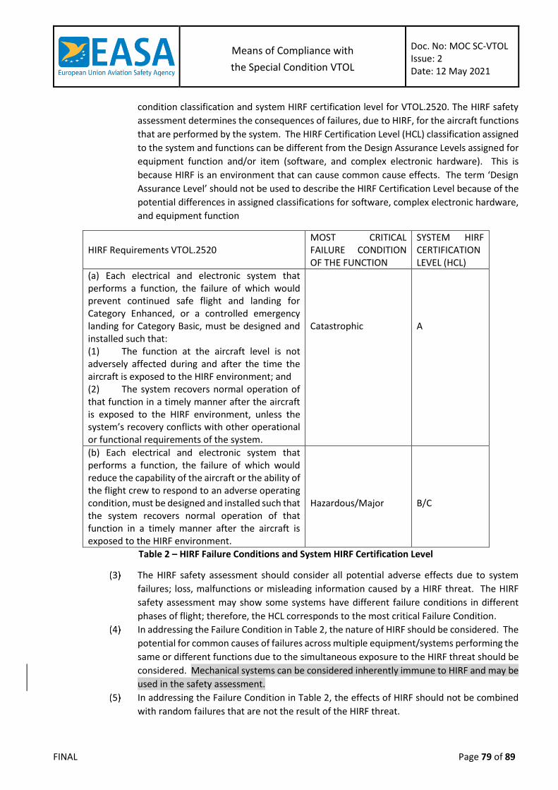
Means of Compliance with
the Special Condition VTOL
Doc. No: MOC SC-VTOL Issue: 2 Date: 12 May 2021
FINAL Page 79 of 89
condition classification and system HIRF certification level for VTOL.2520. The HIRF safety
assessment determines the consequences of failures, due to HIRF, for the aircraft functions
that are performed by the system. The HIRF Certification Level (HCL) classification assigned
to the system and functions can be different from the Design Assurance Levels assigned for
equipment function and/or item (software, and complex electronic hardware). This is
because HIRF is an environment that can cause common cause effects. The term ‘Design
Assurance Level’ should not be used to describe the HIRF Certification Level because of the
potential differences in assigned classifications for software, complex electronic hardware,
and equipment function
HIRF Requirements VTOL.2520
MOST CRITICAL FAILURE CONDITION OF THE FUNCTION
SYSTEM HIRF CERTIFICATION LEVEL (HCL)
(a) Each electrical and electronic system that performs a function, the failure of which would prevent continued safe flight and landing for Category Enhanced, or a controlled emergency landing for Category Basic, must be designed and installed such that: (1) The function at the aircraft level is not adversely affected during and after the time the aircraft is exposed to the HIRF environment; and (2) The system recovers normal operation of that function in a timely manner after the aircraft is exposed to the HIRF environment, unless the system’s recovery conflicts with other operational or functional requirements of the system.
Catastrophic
A
(b) Each electrical and electronic system that performs a function, the failure of which would reduce the capability of the aircraft or the ability of the flight crew to respond to an adverse operating condition, must be designed and installed such that the system recovers normal operation of that function in a timely manner after the aircraft is exposed to the HIRF environment.
Hazardous/Major
B/C
Table 2 – HIRF Failure Conditions and System HIRF Certification Level
The HIRF safety assessment should consider all potential adverse effects due to system
failures; loss, malfunctions or misleading information caused by a HIRF threat. The HIRF
safety assessment may show some systems have different failure conditions in different
phases of flight; therefore, the HCL corresponds to the most critical Failure Condition.
In addressing the Failure Condition in Table 2, the nature of HIRF should be considered. The
potential for common causes of failures across multiple equipment/systems performing the
same or different functions due to the simultaneous exposure to the HIRF threat should be
considered. Mechanical systems can be considered inherently immune to HIRF and may be
used in the safety assessment.
In addressing the Failure Condition in Table 2, the effects of HIRF should not be combined
with random failures that are not the result of the HIRF threat.
Means of Compliance with
the Special Condition VTOL
Doc. No: MOC SC-VTOL Issue: 2 Date: 12 May 2021
FINAL Page 80 of 89
Due to the similar approach in the safety assessment process related to IEL and HIRF, the
System Certification Levels for HIRF and Lightning are usually the same.
(d) HIRF Compliance Verification
By applying the ‘Net Safety Benefit’ approach1 on the lower HIRF Group, VTOL.2520 (b) is
not applicable for level C system of HIRF Groups I and II, it could be removed from the
Compliance Verification.
HIRF Groups I and II
(i) For Level A Non-Display Systems:
(A) Follow AMC 20-158; or
(B) Conduct Equipment/System testing using the following default levels:
Conducted susceptibility testing with the Generic transfer function for
aircraft (according to VTOL shape and size) extrapolated to the HIRF
Environment III (as defined in Section 5) corresponding to the EUROCAE
ED-14G section 20 categories Y or W.
Radiated Susceptibility testing with Generic attenuation curves
(depending on equipment location) extrapolated to the HIRF
Environment III (as defined in Section 5) corresponding to the EUROCAE
ED-14G section 20 categories L, G or F
Fail/Pass Criteria; when subjected to the HIRF Environment, it could be
acceptable that redundant equipment is/are subject to adverse effects,
provided that the Level A function is maintained at the aircraft level and
all the Equipment/Systems that are required in normal operation
recover manually or automatically, in a timely manner, this function
after the threat.
(ii) For Level A Display Systems:
(A) Follow the AMC 20-158; or
(B) Conduct Equipment/System testing using the following default levels:
Conducted susceptibility testing ?with the Generic transfer function for
aircraft (according to VTOL shape and size) extrapolated to the HIRF
Environment I (as defined in Section 5) corresponding to the EUROCAE
ED-14G section 20 categories O or M.
Radiated Susceptibility testing with Generic attenuation curves
(depending on equipment location) extrapolated to the HIRF
Environment I (as defined in Section 5) corresponding to the EUROCAE
ED-14G section 20 categories G, F or D.
Fail/Pass Criteria; when subjected to the HIRF Environment, it could be
acceptable that redundant equipment is/are subject to adverse effects,
provided that the Level A function is maintained at the aircraft level and
all the Equipment/Systems that are required in normal operation
1 For additional information, refer to the EASA Proposed Certification Memorandum CM-SA-001 published in the EASA Website: Proposed Certification Memorandum CM-SA-001 - Net Safety Benefit - Issue 01 | EASA (europa.eu)

Means of Compliance with
the Special Condition VTOL
Doc. No: MOC SC-VTOL Issue: 2 Date: 12 May 2021
FINAL Page 81 of 89
recover manually or automatically, in a timely manner, this function
after the threat.
(iii) For Level B Systems:
(A) Follow the AMC 20-158 (by using Equipment HIRF Test Levels 1 or 2 as defined in
Section 5); or
(B) Conduct Equipment/System testing as defined in (d) (2) (ii) (B) (a) and (b); when
submitted to the HIRF Environment, if the Equipment/System subject to adverse
effects does not to recover its level B function after the threat, the method proposed
by the AMC 20-158 for Level B systems in (d) (2) (iii) (A) can be used as an
alternatively.
HIRF Group III
(i) For Level A Non-Display Systems:
(A) Follow the AMC 20-158; or
(B) Conduct Equipment/System testing using the following default levels:
Conducted susceptibility testing with the real transfer function of the
aircraft (determined by Low Level coupling test, analysis, combination
of both or similarity) extrapolated to the HIRF Environment III (as
defined in Section 5).
Radiated Susceptibility testing with real attenuation curves
(determined by Low level Testing, analysis, combination of both or
similarity) extrapolated to the HIRF Environment III (as defined in
Section 5).
Fail/Pass Criteria; when submitted subjected to the HIRF Environment,
it could be acceptable that redundant equipment is/are subject to
adverse effects, provided that the Level A function is maintained at the
aircraft level and all the Equipment/Systems that are required in normal
operation recover manually or automatically, in a timely manner, this
function after the threat.
(ii) For Level A Display Systems:
(A) Follow the AMC 20-158; or
(B) Conduct Equipment/System testing using the following default levels:
Conducted susceptibility with the Generic transfer function for aircraft
(according to VTOL shape and size) extrapolated to the HIRF
Environment I (as defined in Section 5) corresponding to the EUROCAE
ED-14G section 20 categories O or M.
Radiated Susceptibility with Generic attenuation curves (depending on
equipment location) applied HIRF Environment I (as defined in Section
5) corresponding to the EUROCAE ED-14G section 20 categories G, F or
D.
Fail/Pass Criteria; when subjected to the HIRF Environment, it could be
acceptable that redundant equipment are subject to adverse effect,

Means of Compliance with
the Special Condition VTOL
Doc. No: MOC SC-VTOL Issue: 2 Date: 12 May 2021
FINAL Page 82 of 89
provided the Level A function is maintained at the aircraft level and all
the Equipment/Systems required in normal operation recover manually
or automatically, in a timely manner, this function after the threat.
(iii) For Level B Systems:
(A) Follow the AMC 20-158 (by using Equipment HIRF Test Levels 1 or 2 as defined in
Section 5); or
(B) Conduct Equipment/System testing as defined in (d) (3) (ii) (a) and (b); when
submitted to the HIRF Environment, if the Equipment/System, subject to adverse
effects, does not to recover to its level B function after the threat, the method
proposed by the AMC 20-158 for Level B systems in (d) (3) (iii) (A) can be used as an
alternative.
(iv) For Level C Systems:
(A) Follow the AMC 20-158 (by using Equipment HIRF Test Level 3 as defined in Section
5); or
(B) Conduct Equipment/System testing as defined in (d) (3) (ii) (a) and (b); when
submitted to the HIRF Environment, if the Equipment/System, subject to adverse
effects, does not to recover to its level C function after the threat, the method
proposed by the AMC 20-158 for Level C systems in (d) (3) (iv)(A) can be used as an
alternative.
HIRF Testing for Level A systems considerations;
(i) The Test Levels for upper HIRF Group can also be used for lower HIRF Groups; for
instance the use of real transfer function and attenuation curves and/or more severe
External HIRF Environment can be used for Level A Systems of HIRF Groups I/II.
(ii) Equipment testing is acceptable when it is shown that the interdependencies between
equipment performing a function are understood and each equipment is tested and
monitored to verify that there are no unacceptable upsets of the function.
(iii) If similar equipment are used to perform the same function; the test can be limited to
a single equipment.
Level A System architecture consideration; when a Level A system comprises redundant
channels/equipment that perform the same level A function, it is permitted to limit the
system to the channels/equipment that are required in normal operation provided that they
are not susceptible when they comply with VTOL.2520(a); for instance if it is demonstrated
that the primary channels comply with VTOL.2520(a) without the support of the back-up
channel, this channel is not requested to be exposed to the HIRF Environment I/III, however
this back-up channel should be considered to be a level B system.
HIRF Environments and Equipment HIRF Test Levels
This Section specifies the HIRF environments and equipment HIRF test levels for electrical and electronic systems
under VTOL.2520.
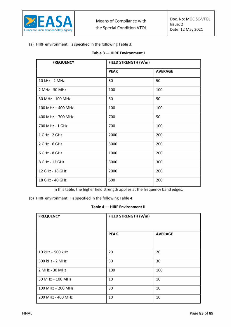
Means of Compliance with
the Special Condition VTOL
Doc. No: MOC SC-VTOL Issue: 2 Date: 12 May 2021
FINAL Page 83 of 89
(a) HIRF environment I is specified in the following Table 3:
Table 3 — HIRF Environment I
FREQUENCY FIELD STRENGTH (V/m)
PEAK AVERAGE
10 kHz - 2 MHz 50 50
2 MHz - 30 MHz 100 100
30 MHz - 100 MHz 50 50
100 MHz – 400 MHz 100 100
400 MHz – 700 MHz 700 50
700 MHz - 1 GHz 700 100
1 GHz - 2 GHz 2000 200
2 GHz - 6 GHz 3000 200
6 GHz - 8 GHz 1000 200
8 GHz - 12 GHz 3000 300
12 GHz - 18 GHz 2000 200
18 GHz - 40 GHz 600 200
In this table, the higher field strength applies at the frequency band edges.
(b) HIRF environment II is specified in the following Table 4:
Table 4 — HIRF Environment II
FREQUENCY FIELD STRENGTH (V/m)
PEAK
AVERAGE
10 kHz – 500 kHz 20 20
500 kHz - 2 MHz 30 30
2 MHz - 30 MHz 100 100
30 MHz – 100 MHz 10 10
100 MHz – 200 MHz 30 10
200 MHz - 400 MHz 10 10

Means of Compliance with
the Special Condition VTOL
Doc. No: MOC SC-VTOL Issue: 2 Date: 12 May 2021
FINAL Page 84 of 89
FREQUENCY FIELD STRENGTH (V/m)
PEAK
AVERAGE
400 MHz - 1 GHz 700 40
1 GHz - 2 GHz 1300 160
2 GHz - 4 GHz 3000 120
4 GHz - 6 GHz 3000 160
6 GHz - 8 GHz 400 170
8 GHz - 12 GHz 1230 230
12 GHz – 18 GHz 730 190
18 GHz - 40 GHz 600 150
In this table, the higher field strength applies at the frequency band edges.
(c) HIRF environment III is specified in the following Table 5:
Table 5 — HIRF Environment III
FREQUENCY FIELD STRENGTH (V/m)
PEAK
AVERAGE
10 kHz – 100 kHz 150 150
100 kHz - 400 MHz 200 200
400 MHz - 700 MHz 730 200
700 MHz – 1 GHz 1400 240
1 GHz - 2 GHz 5000 250
2 GHz - 4 GHz 6000 490
4 GHz - 6 GHz 7200 400
6 GHz - 8 GHz 1100 170
8 GHz - 12 GHz 5000 330
12 GHz – 18 GHz 2000 330

Means of Compliance with
the Special Condition VTOL
Doc. No: MOC SC-VTOL Issue: 2 Date: 12 May 2021
FINAL Page 85 of 89
FREQUENCY FIELD STRENGTH (V/m)
PEAK
AVERAGE
18 GHz - 40 GHz 1000 420
In this table, the higher field strength applies at the frequency band edges.
(d) Equipment HIRF Test Level 1.
Equipment Level Test ED-14G (or later Revision) Cat R for both conducted and radiated susceptibility.
(e) Equipment HIRF Test Level 2.
Equipment HIRF test level 2 is HIRF environment II in table 4 of this Section reduced by acceptable generic
aircraft transfer function and attenuation curves. Testing should cover the frequency band of 10 kHz to 8
GHz.
(f) Equipment HIRF Test Level 3.
Equipment Level Test ED-14G (or later Revision) Cat T for both conducted and radiated susceptibility.
MOC VTOL.2555 Installation of recorders
This MOC is applicable to each recorder installed to comply with VTOL.2555.
(a) General:
The recorder should have an ETSO authorisation against one of the following ETSOs or a later equivalent:
ETSO-C123b; or
ETSO-C124b; or
ETSO-2C197
(b) Recorder installation:
The container of the recording medium should be located and mounted so as to minimise the probability of
the container rupturing or the recording medium being destroyed as a result of impact with the Earth’s
surface or of heat damage caused by a post-impact fire.
The structural provisions within the aircraft for the mounting of the recorder should be able to withstand
the loads resulting from severe vibration (such as those resulting from rotor imbalance). In addition, the
strength of the local attachments should be able to withstand the crash safety loads in CS 27.561(b)(3).
If the recorder has an erasure device or function, the installation must be designed to minimise the
probability of inadvertent operation and actuation of the erasure device or function during crash impact.
(c) Recorder identification:
A high proportion of the area of the outer surfaces of the container of the memory medium should be
coloured bright orange.

Means of Compliance with
the Special Condition VTOL
Doc. No: MOC SC-VTOL Issue: 2 Date: 12 May 2021
FINAL Page 86 of 89
The height, width and depth of the container of the memory medium must each be 4 cm (1.5 inches) or
greater
(d) Recorder characteristics:
The recorder should:
Permit quick downloading of the flight parameters without having to remove the recorder;
Be capable of retaining the flight parameters that are recorded during at least the preceding
5 hours and the audio recording during at least the preceding 2 hours;
Automatically start to record as early as possible after power-on and in any case prior to the
aircraft being capable of moving under its own power;
Continue to record until the termination of the flight when the aircraft is no longer capable
of moving under its own power;
If the recorder has a recording duration of less than 25 hours, have a means for the flight
crew to stop the recording upon completion of the flight in such a way that re-enabling the
recording is only possible by a dedicated manual action.
(e) Flight Parameters and audio recording:
The recorder, or the combination of recorders installed to comply with VTOL.2555, should:
Record the flight parameters required to accurately determine the flight path, speed,
attitude, engine power, operation and configuration of the VTOL aircraft. The minimum list
of flight parameters to be recorded is provided in paragraphs (h) and (j). All recorded
parameter values should be accurately time-stamped according to a common time
reference and be recorded at a rate not below 4 Hz;
For aircraft with a minimum flight crew of two pilots, simultaneously record, on separate
channels and with reference to a timescale:
(i) The aural environment of the cockpit (area microphone);
(ii) Pilots’ headset audio, including but not limited to voice communications, audio signals
for navigation aids, aural alerts.
(f) Maintenance instructions:
When developing the ICA for the recorder systems, the applicant should address all the
failures that may affect their correct functioning or the quality of the recorded information.
Note: ‘Recorder systems’ designates the recorders and their dedicated equipment (e.g.
dedicated sensors or transducers, dedicated data busses, dedicated power source…).
Examples of failures (indicative and non-exhaustive list):
(i) Loss of the recording function or of the acquisition function of the recorder;
(ii) Failure of a means to facilitate the finding of the recording medium after an accident
(e.g. an underwater locating device or an emergency locator transmitter attached to
the recorder);
(iii) Failure of a means to detect a crash impact (for the purpose of stopping the recording
after a crash impact, or for the purpose of deploying the recorder if it is deployable);
(iv) Failure of any power source dedicated to the recorder (e.g. dedicated battery);
(v) Failure of the start-and-stop function;
Means of Compliance with
the Special Condition VTOL
Doc. No: MOC SC-VTOL Issue: 2 Date: 12 May 2021
FINAL Page 87 of 89
(vi) Failure of a sensor dedicated to the recorder system;
(vii) For flight parameters recording, when any required parameter is missing, or is not
correctly recorded;
(viii) For audio recording (if applicable):
(ix) Any required audio signal is missing, or is recorded with an audio quality that is rated
‘poor’ (refer to the example of audio quality rating provided in Section 9 of AMC
25.1459);
(x) Failure of a transducer or amplifier dedicated to the recorder system (e.g. failure of
the cockpit area microphone).
(g) Data transmission & ground recording: [Reserved]
(h) The following flight parameters should as a minimum be recorded with a recording resolution at least
as high as specified in EUROCAE Documents ED-155 or ED-112:
Time
Altitude
Latitude
Longitude
Indicated airspeed or calibrated airspeed
Groundspeed
Outside Air Temperature (OAT)
Heading (magnetic or true)
Track
Vertical speed
Pitch attitude
Roll attitude
Longitudinal acceleration (body axis)
Normal acceleration
Lateral acceleration
Roll rate or Roll acceleration
Pitch rate or Pitch acceleration
Yaw rate or yaw acceleration
If electric engines are used:
(i) Electric Engines: rotation speed of each rotor (in RPM)
(ii) Electric Engines: health status of each electric engine controller
(iii) Electric Engines: temperature of each electric engine
(iv) Electric Engines: temperature of each electric engine controller
(v) Electric Engines: measured electrical current for each electric engine
(vi) For liquid cooled electric engines: pressure and temperature of the cooling liquid
Flight controls
(i) Pilot input positions on all axis and corresponding flight control,
(ii) Outputs (e.g. target RPM for each electric engine, flight surface positions, …)
Status of each flight control computer
Wings angle (if applicable)
Nacelles angles (if applicable)

Means of Compliance with
the Special Condition VTOL
Doc. No: MOC SC-VTOL Issue: 2 Date: 12 May 2021
FINAL Page 88 of 89
Propeller pitch (for each variable pitch propeller)
Air-Ground status such as Weight on Wheels or equivalent parameter
Alerts (including master warning and master caution status)
Manual voice transmission keying (if voice communications are used)
For each battery used for propulsion and/or flight controls:
(i) Health status, State Of Charge (SOC), voltage, temperature, current flow,
(ii) if available:
(A) State of Power (SOP); or
(B) Calculated remaining flight time.
Health status of each electrical distribution unit (e.g. distribution units, converters)
contributing to the propulsion and/or flight controls
Status of the battery management system (if any)
If combustion engine(s) are used:
(i) Fuel parameters;
(ii) Oil pressure and oil temperature;
(iii) Parameters required to determine propulsive thrust or power delivered;
(iv) Turbine RPM (if applicable);
(v) FADEC health status (if applicable);
(vi) Aircraft inputs used by the FADEC (if applicable);
(vii) Any electrical current generation; and
(viii) Any other parameter subject to a limitation
(i) In addition, the following flight parameters should be recorded if they are used by the aircraft systems
or are available for use by the pilot to operate the aircraft. They should be recorded with a recording
resolution at least as high as specified in EUROCAE Documents ED-155 or ED-112:
Active AFCS mode
Radio altitude or terrain elevation
Current navigation source,
Vertical and lateral deviation with respect to current active navigation path
DME 1 & 2 distances
Drift angle
Wind speed
Wind direction
Landing gear position
Ice: ice detection, status of de-icing or anti-icing system
Electric Engine: vibration level
Traffic advisories or alerts, if installed (e.g. ADS-B IN, ACAS…)
Obstacle and terrain alerts, if installed (e.g. TAWS, …)
(j) If the VTOL aircraft has datalink communication capabilities, the following should be recorded:
data link communication messages to and from the aircraft, including messages applying to
the following applications:
(i) data link initiation and termination,

Means of Compliance with
the Special Condition VTOL
Doc. No: MOC SC-VTOL Issue: 2 Date: 12 May 2021
FINAL Page 89 of 89
(ii) controller-pilot communication,
(iii) addressed surveillance,
(iv) flight information, including weather data (if required for operation),
(v) aircraft broadcast surveillance,
(vi) aircraft operational control data, and
(vii) graphics.
information that enables correlation to any associated records related to data link
communications and stored separately from the helicopter; and
information on the time and priority of data link communications messages, taking into
account the system’s architecture.