me1720 software, autocad 2d lesson 3 – dimensions...
TRANSCRIPT
ME1720 Software, AutoCAD 2D Lesson 3 – Dimensions Document URL: http://ide20.com/upload/ModuleAC/Lesson03_2014JBS.pdf Developer: [email protected], 8/2015 update by [email protected]
Copyright 2015, Missouri S&T
1
AutoCAD 2D Lesson 3 – Dimensions Pre-reqs/Technical Skills
• Basic computer use • Completion of AutoCAD Lessons 1&2
Expectations • Read lesson material • Implement steps in software while reading through lesson material • Complete quiz on Blackboard • Submit completed assignment on Blackboard • Ask questions as needed
Objectives/Measurables • Learn to use dimensions AutoCAD, measured via assignment score • Learn various features in AutoCAD, measured via Blackboard quiz score
Lecture Topics • Adding Dimensions • Adding Notes • Simple Tolerances
Table of Contents
AutoCAD 2D ........................................................................................................................................ 1 Lesson 3 – Dimensions .......................................................................................................................................................................... 1
Pre-reqs/Technical Skills ........................................................................................................................................................................... 1 Expectations ..................................................................................................................................................................................................... 1 Objectives/Measurables ............................................................................................................................................................................. 1 Lecture Topics ................................................................................................................................................................................................. 1
Introduction – AutoCAD 2014 ............................................................................................................................................................ 1 Adding Dimensions ................................................................................................................................................................................. 1 Linear dimensions ................................................................................................................................................................................... 2 Circular dimensions ............................................................................................................................................................................... 5 Notes ........................................................................................................................................................................................................... 13 Tolerances ................................................................................................................................................................................................ 15 Assignment ............................................................................................................................................................................................... 16
Introduction – AutoCAD 2014 AutoCAD is a 2D and 3D computer aided drafting (CAD) program. It is used primarily for mechanical and architectural drafting. Essentially, it provides a computer-based method for producing engineering drawings. The 2010+ versions integrate the Windows Ribbon interface which may be unfamiliar to those who have used earlier versions. This module uses the default Ribbon interface and is designed for those new to AutoCAD or those who wish to use the new Ribbon interface.
Adding Dimensions AutoCAD is frequently used to generate printed drawings. These drawing can be used to communicate aspects of a design to other people. In technical applications, including dimensions is necessary to completely convey the design. AutoCAD allows you to add dimensions to drawn elements and include tolerances and text notes.
ME1720 Software, AutoCAD 2D Lesson 3 – Dimensions Document URL: http://ide20.com/upload/ModuleAC/Lesson03_2014JBS.pdf Developer: [email protected], 8/2015 update by [email protected]
Copyright 2015, Missouri S&T
2
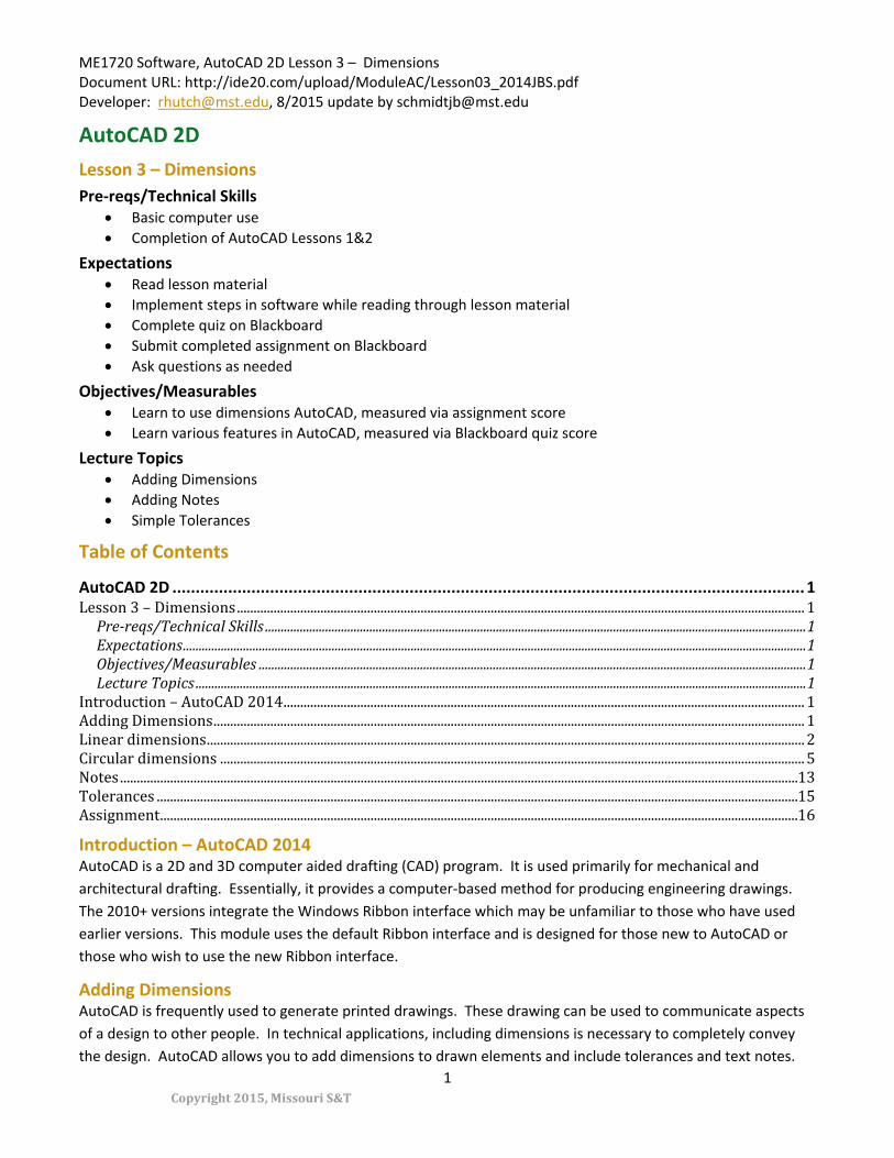
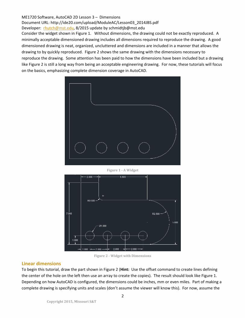
Consider the widget shown in Figure 1. Without dimensions, the drawing could not be exactly reproduced. A minimally acceptable dimensioned drawing includes all dimensions required to reproduce the drawing. A good dimensioned drawing is neat, organized, uncluttered and dimensions are included in a manner that allows the drawing to by quickly reproduced. Figure 2 shows the same drawing with the dimensions necessary to reproduce the drawing. Some attention has been paid to how the dimensions have been included but a drawing like Figure 2 is still a long way from being an acceptable engineering drawing. For now, these tutorials will focus on the basics, emphasizing complete dimension coverage in AutoCAD.
Figure 1 - A Widget
Figure 2 - Widget with Dimensions
Linear dimensions To begin this tutorial, draw the part shown in Figure 2 (Hint: Use the offset command to create lines defining the center of the hole on the left then use an array to create the copies). The result should look like Figure 1. Depending on how AutoCAD is configured, the dimensions could be inches, mm or even miles. Part of making a complete drawing is specifying units and scales (don’t assume the viewer will know this). For now, assume the

ME1720 Software, AutoCAD 2D Lesson 3 – Dimensions Document URL: http://ide20.com/upload/ModuleAC/Lesson03_2014JBS.pdf Developer: [email protected], 8/2015 update by [email protected]
Copyright 2015, Missouri S&T
3
units to be in inches. The first dimension to be added is the 7” vertical at the left. This gives the total height of the part. To add dimensions, switch to the Annotate tab (Figure 3).
Figure 3 - Annotate Tab
Look over the various options in this tab. They all relate to adding dimensions and notes to your drawings. To add a simple linear dimension, click the down arrow under Dimension and select Linear (Figure 4).
Figure 4 - Adding a Linear Dimension
The first step in adding a linear dimension is to select a start point (Figure 5). Click on the bottom-left corner of the object to select it (make sure you see the endpoint snap come up to ensure you are at the true endpoint and not just close).

ME1720 Software, AutoCAD 2D Lesson 3 – Dimensions Document URL: http://ide20.com/upload/ModuleAC/Lesson03_2014JBS.pdf Developer: [email protected], 8/2015 update by [email protected]
Copyright 2015, Missouri S&T
4
Figure 5 - Setting the First Point
Now click to select the top-left corner of the object (Figure 6).
Figure 6 - Setting the Second Point
A dimension will appear attached to your mouse cursor, drag the dimension away from the part to a convenient location. This location can be changed later (and even set a fixed distance away). For now, place it as shown in (Figure 7).
ME1720 Software, AutoCAD 2D Lesson 3 – Dimensions Document URL: http://ide20.com/upload/ModuleAC/Lesson03_2014JBS.pdf Developer: [email protected], 8/2015 update by [email protected]
Copyright 2015, Missouri S&T
5
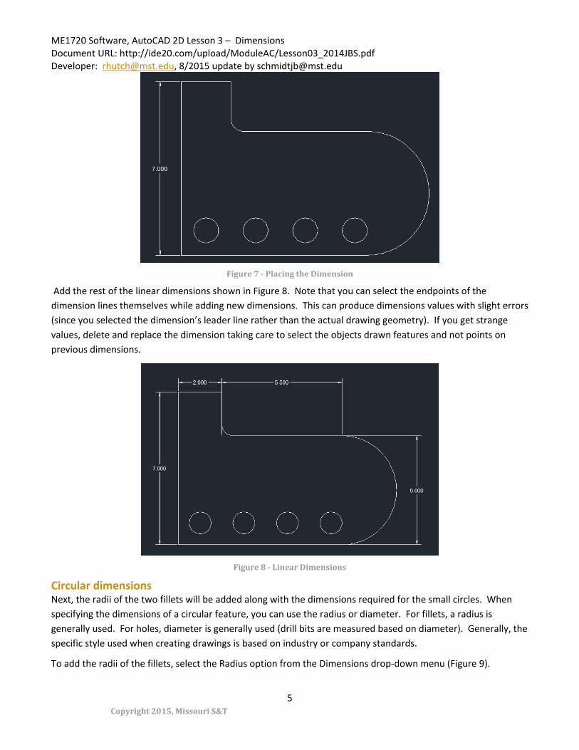
Figure 7 - Placing the Dimension
Add the rest of the linear dimensions shown in Figure 8. Note that you can select the endpoints of the dimension lines themselves while adding new dimensions. This can produce dimensions values with slight errors (since you selected the dimension’s leader line rather than the actual drawing geometry). If you get strange values, delete and replace the dimension taking care to select the objects drawn features and not points on previous dimensions.
Figure 8 - Linear Dimensions
Circular dimensions Next, the radii of the two fillets will be added along with the dimensions required for the small circles. When specifying the dimensions of a circular feature, you can use the radius or diameter. For fillets, a radius is generally used. For holes, diameter is generally used (drill bits are measured based on diameter). Generally, the specific style used when creating drawings is based on industry or company standards.
To add the radii of the fillets, select the Radius option from the Dimensions drop-down menu (Figure 9).

ME1720 Software, AutoCAD 2D Lesson 3 – Dimensions Document URL: http://ide20.com/upload/ModuleAC/Lesson03_2014JBS.pdf Developer: [email protected], 8/2015 update by [email protected]
Copyright 2015, Missouri S&T
6
Figure 9 - Radius Dimensions
Now select the circular arc to be dimensioned (Figure 10). Start with the smaller fillet (click on it to select it).
Figure 10 - Selecting the Arc
Like with linear dimensions, the dimension will appear attached to the mouse cursor. Move to a suitable location and click to add it (Figure 11).

ME1720 Software, AutoCAD 2D Lesson 3 – Dimensions Document URL: http://ide20.com/upload/ModuleAC/Lesson03_2014JBS.pdf Developer: [email protected], 8/2015 update by [email protected]
Copyright 2015, Missouri S&T
7
Figure 11 - Placing the Dimension
Now add the radius of the larger fillet (Figure 12).
Figure 12 - Dimension Added to the Large Fillet
Now, we need to specify the location of each of the circles. To do this, we will first add center marks then dimensions to these marks. To add a center mark, click the down arrow next to Dimensions (Figure 13).
Figure 13 - Dimensions Button
Now click the Center Mark button (Figure 14).

ME1720 Software, AutoCAD 2D Lesson 3 – Dimensions Document URL: http://ide20.com/upload/ModuleAC/Lesson03_2014JBS.pdf Developer: [email protected], 8/2015 update by [email protected]
Copyright 2015, Missouri S&T
8
Figure 14 - Adding a Center Mark
Select the circle that needs the center mark (Figure 15).
Figure 15 - Selecting the Circle
The mark will be added (Figure 16).
Figure 16 - A Center Mark
Now add marks to all four circles (Figure 17).

ME1720 Software, AutoCAD 2D Lesson 3 – Dimensions Document URL: http://ide20.com/upload/ModuleAC/Lesson03_2014JBS.pdf Developer: [email protected], 8/2015 update by [email protected]
Copyright 2015, Missouri S&T
9
Figure 17 - All Center Marks Added
Linear dimensions can now be added to specify the location of the holes using the center marks (Figure 18).
Figure 18 - Holes Dimensioned
Note that the height of only the first circle is included. To be clear that this dimension applies to all of the circles, the leader of the dimension should extend across all circles. To move the leader for the dimension, click to select the dimension. You can now drag the leader lines and dimension center around. Move the leader from the center of the first circle (Figure 19) over to the center of the fourth circle (from the left).
Figure 19 - Moving the Leader
Also note that there are crossed leader lines (the 1” and 7” dimensions). This is generally a bad practice as it clutters a drawing. To correct this, move both dimensions. To move a dimension, click to select it, then click the drag handle at the center of the dimension number, you can now move it (Figure 20).
ME1720 Software, AutoCAD 2D Lesson 3 – Dimensions Document URL: http://ide20.com/upload/ModuleAC/Lesson03_2014JBS.pdf Developer: [email protected], 8/2015 update by [email protected]
Copyright 2015, Missouri S&T
10
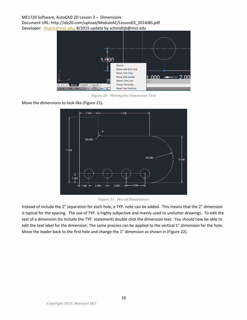
Figure 20 - Moving the Dimension Text
Move the dimensions to look like (Figure 21).
Figure 21 - Moved Dimensions
Instead of include the 2” separation for each hole, a TYP. note can be added. This means that the 2” dimension is typical for the spacing. The use of TYP. is highly subjective and mainly used to unclutter drawings. To edit the text of a dimension (to include the TYP. statement) double click the dimension text. You should now be able to edit the text label for the dimension. The same process can be applied to the vertical 1” dimension for the hole. Move the leader back to the first hole and change the 1” dimension as shown in (Figure 22).

ME1720 Software, AutoCAD 2D Lesson 3 – Dimensions Document URL: http://ide20.com/upload/ModuleAC/Lesson03_2014JBS.pdf Developer: [email protected], 8/2015 update by [email protected]
Copyright 2015, Missouri S&T
11
Figure 22 - Editing Text
The drawing should look like Figure 23. Note that you might have mixed precision among the dimensions (e.g. some have three decimal places some have four). Once again, the “correct” format depends on the standards of your industry. To change the precision of a dimension, click to select the dimension then right-click to get the pop-up shown in Figure 24.
Figure 23 - Typical Dimensions
Select the Precision option and select a number of decimal places. Set the precision of each dimension to three decimal places for now (Figure 24).

ME1720 Software, AutoCAD 2D Lesson 3 – Dimensions Document URL: http://ide20.com/upload/ModuleAC/Lesson03_2014JBS.pdf Developer: [email protected], 8/2015 update by [email protected]
Copyright 2015, Missouri S&T
12
Figure 24 - Setting Precision
The result should look like Figure 25 (in this case, no change from Figure 23).
Figure 25 - All Precisions Changed
Add the hole size dimension now. For the hole add a diameter-based dimension rather than the radius-based dimension used for the fillets. Select Diameter from the Dimension dropdown. Select the hole and place the dimension as shown in Figure 26.
ME1720 Software, AutoCAD 2D Lesson 3 – Dimensions Document URL: http://ide20.com/upload/ModuleAC/Lesson03_2014JBS.pdf Developer: [email protected], 8/2015 update by [email protected]
Copyright 2015, Missouri S&T
13
Figure 26 - Hole Size Added
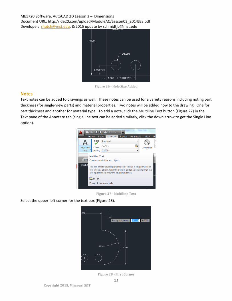
Notes Text notes can be added to drawings as well. These notes can be used for a variety reasons including noting part thickness (for single-view parts) and material properties. Two notes will be added now to the drawing. One for part thickness and another for material type. To add a note, click the Multiline Text button (Figure 27) in the Text pane of the Annotate tab (single line text can be added similarly, click the down arrow to get the Single Line option).
Figure 27 - Multiline Text
Select the upper-left corner for the text box (Figure 28).
Figure 28 - First Corner
ME1720 Software, AutoCAD 2D Lesson 3 – Dimensions Document URL: http://ide20.com/upload/ModuleAC/Lesson03_2014JBS.pdf Developer: [email protected], 8/2015 update by [email protected]
Copyright 2015, Missouri S&T
14
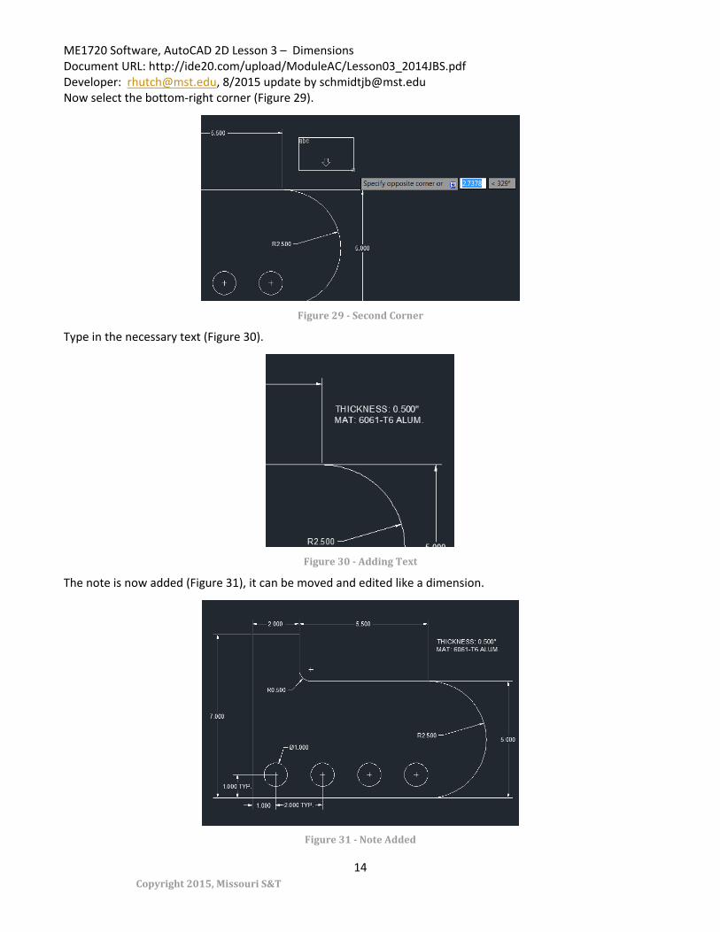
Now select the bottom-right corner (Figure 29).
Figure 29 - Second Corner
Type in the necessary text (Figure 30).
Figure 30 - Adding Text
The note is now added (Figure 31), it can be moved and edited like a dimension.
Figure 31 - Note Added

ME1720 Software, AutoCAD 2D Lesson 3 – Dimensions Document URL: http://ide20.com/upload/ModuleAC/Lesson03_2014JBS.pdf Developer: [email protected], 8/2015 update by [email protected]
Copyright 2015, Missouri S&T
15
Tolerances When a part is being manufactured, it can only be produced to a maximum level of precision determined by the manufacturing process. No two manufactured parts will ever be truly identical. The allowable level of precision required for the part must be determined by the part’s designer and specified on the drawing. Tolerances are a critical aspect of design and entire courses are devoted to proper assignment and management of them. As a result, how to properly tolerance a drawing cannot be covered in this tutorial. However, the basic method of adding a simple +/- dimension tolerance will be covered.
To add a simple +/- tolerance, click the down arrow next to Dimensions in the Annotate tab. Now click on the Tolerance button (Figure 32).
Figure 32 - Adding a Tolerance
The Geometric Tolerance dialog will open (Figure 33). In this dialog you can add tolerance symbols and numbers. For now, type in the text as shown and click OK.
Figure 33 - Geometric Tolerance Dialog

ME1720 Software, AutoCAD 2D Lesson 3 – Dimensions Document URL: http://ide20.com/upload/ModuleAC/Lesson03_2014JBS.pdf Developer: [email protected], 8/2015 update by [email protected]
Copyright 2015, Missouri S&T
16
You can now place the tolerance as shown in (Figure 34).
Figure 34 - Tolerance Placed
If every dimension on a drawing does not include a tolerance, a default tolerance generally must be included. This can be done with a note.
Assignment Create the drawing shown in Figure 34. Include the tolerance on the 7 inch height and the note specifying the thickness and material.
• The part itself (3) • Linear dimensions (3) • Circular and hole placement dimensions (3) • Note (3) • Tolerance (3)
Submit a .dwg file to the appropriate link under Assignments in Blackboard.