me 3560 fluid mechanics - homepages at wmuhomepages.wmich.edu/~s9montef/me3560chapterii.pdf · me...
TRANSCRIPT

ME3560 – Fluid Mechanics
Chapter II. Fluid Statics
Spring 2018
1
ME 3560 Fluid Mechanics
Chapter II. Fluid Statics

ME3560 – Fluid Mechanics
Chapter II. Fluid Statics
Spring 2018
2
• Fluid power cylinder.• Aquarium observation
windows.
• Storage tank.
• Tank with curved surface. • Retaining wall.
• Fluid reservoir and hatch.
Examples of cases where forces on submerged surfaces must be calculated.

ME3560 – Fluid Mechanics
Chapter II. Fluid Statics
Spring 2018
3
2.1 Pressure at a Point• The term pressure is used to indicate the normal force per unit area at agiven point acting on a given plane within the fluid mass of interest.
zszz
ysyy
azyxzyxsxpyxpF
azyxsxpzxpF
22cos
2sin
ME3560 – Fluid Mechanics
Chapter II. Fluid Statics
Spring 2018
4
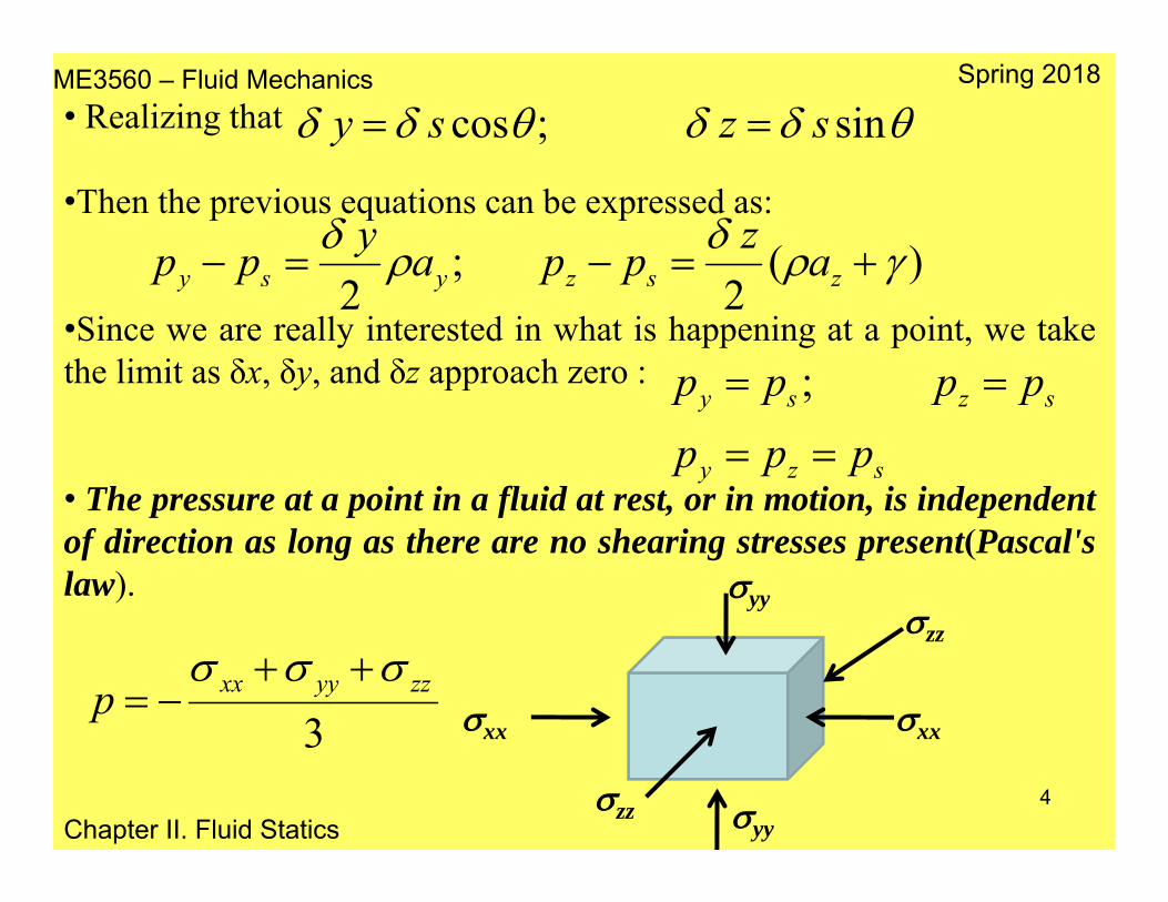
• Realizing that
•Then the previous equations can be expressed as:
•Since we are really interested in what is happening at a point, we takethe limit as δx, δy, and δz approach zero :
• The pressure at a point in a fluid at rest, or in motion, is independentof direction as long as there are no shearing stresses present(Pascal'slaw).
sin;cos szsy
)(2
;2
zszysy azppaypp
szy
szsy
ppp
pppp
;
zz
zz
xx
yy
yy
xx3zzyyxxp

ME3560 – Fluid Mechanics
Chapter II. Fluid Statics
Spring 2018
5
2.2 Basic Equation for Pressure Field• Consider a small rectangular element of fluid.•There are two types of forces acting on this element:•surface forces due to the pressure•body force equal to the weight of the element.
• Let p be the pressure at thecenter of the element bedesignated as p, then thesurface forces in the y directionis:
zxyypp
zxyyppFy
)2
(
)2
(

ME3560 – Fluid Mechanics
Chapter II. Fluid Statics
Spring 2018
6
• Simplifying the previous expression we get:
•Following a similar procedure the surface forces for x and z are:
•The surface forces exerted on the element of fluid can be expressed as:
zyxypFy
zyxzpFzyx
xpF zx
kz
jy
ix
zyxpF
zyxkzpj
ypi
xpF
kFjFiFF
s
s
zyxs
ˆ()ˆ()ˆ()();
)ˆˆˆ(
ˆˆˆ

ME3560 – Fluid Mechanics
Chapter II. Fluid Statics
Spring 2018
7
• By considering the body forces, we can find that the weight of theelement is:
•Adding up body and surface forces, and applying Newton’s 2nd Law weget:
•Which after simplification becomes:
•This is the general equation of motion for a fluid in which there are noshearing stresses.
kzyxkzyxgkW ˆˆˆ
azyxzyxkgp )ˆ(
akgp )ˆ(

ME3560 – Fluid Mechanics
Chapter II. Fluid Statics
Spring 2018
8
2.3 Pressure Variation in a Fluid at Rest• For a fluid at rest, the equation:•Becomes:•Which can also be expressed as:
•These equations show that the pressure does not depend on x or y.•Therefore p depends only on z (vertical direction – depth)
•This is the fundamental equation for fluids at rest and can be used todetermine how pressure changes with elevation.•This equation expresses that the pressure decreases as we move upwardin a fluid at rest.
akgp )ˆ(0ˆ kgp
gzp
yp
xp
00
gdzdp

ME3560 – Fluid Mechanics
Chapter II. Fluid Statics
Spring 2018
9
2.3.1 Incompressible Fluid• A fluid with constant density is called an incompressible fluid.• For liquids the variation in density is usually negligible, even overlarge vertical distances ( and therefore are constant):
2
1
2
1
z
z
p
pdzgdp )( 1221 zzgpp
hghpp 21• The pressure head can bedefined from the previousequation as:
•If p0 is a referencepressure, the pressure at adepth h is
2121 pp
gpph
0php

ME3560 – Fluid Mechanics
Chapter II. Fluid Statics
Spring 2018
10
• As demonstrated, the pressure in a homogeneous, incompressible fluidat rest depends on the depth of the fluid relative to some reference plane,and it is not influenced by the size or shape of the tank or container inwhich the fluid is held. The actual value of the pressure along ABdepends only on the depth, h, the surface pressure, p0, and the specificweight, , of the liquid in the container.
ME3560 – Fluid Mechanics
Chapter II. Fluid Statics
Spring 2018
11
2.3.2 Compressible Fluid• Gases such as air, oxygen, and nitrogen are compressible fluids.
•gas<< liq•Since gas are comparatively small, then p/z is small (even overdistances of several hundred feet the pressure will remain essentiallyconstant for a gas).•Thus the effect of elevation changes on the pressure in gases can beneglected in tanks, pipes.
),( pTfgas

ME3560 – Fluid Mechanics
Chapter II. Fluid Statics
Spring 2018
12
• When the variations in heights are large, on the order of thousands offeet, the variation in must be taken into account.• For an ideal (or perfect) gas the eqn. of state is: which whencombined with
Results in the following relation:
•This equation can be integrated to obtain:
•Finally, it is necessary to specify the nature of the variation oftemperature with elevation. If the temperature has a constant value T0over the range z2 to z1 (isothermal conditions), then
RTp
gdzdp
RTpg
dzdp
2
1
2
1 1
2lnz
z
p
p Tdz
Rg
pp
pdp
0
1212
)(expRT
zzgpp
ME3560 – Fluid Mechanics
Chapter II. Fluid Statics
Spring 2018
13
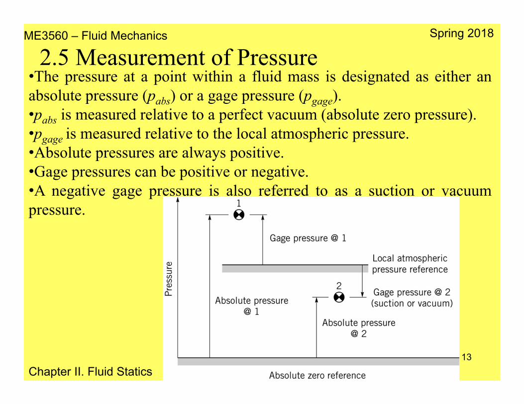
2.5 Measurement of Pressure•The pressure at a point within a fluid mass is designated as either anabsolute pressure (pabs) or a gage pressure (pgage).•pabs is measured relative to a perfect vacuum (absolute zero pressure).•pgage is measured relative to the local atmospheric pressure.•Absolute pressures are always positive.•Gage pressures can be positive or negative.•A negative gage pressure is also referred to as a suction or vacuumpressure.

ME3560 – Fluid Mechanics
Chapter II. Fluid Statics
Spring 2018
14
• Since p=F/A, its units are lb/ft2 (psf), lb/in2
(psi) and N/m2 (Pa)•Pressure can also be expressed as theheight of a column of liquid.•The units will refer to the height of thecolumn (in., ft, mm, m), also the liquid inthe column must be specified (H2O, Hg).•The measurement patm is usually done witha mercury barometer.•The column of mercury will come to anequilibrium position where its weight plusthe force due to the vapor pressure (whichdevelops in the space above the column)balances the force due to the atmosphericpressure.
vaporvaporatm phpghp https://www.youtube.com/watch?v=EkDhlzA-lwI

ME3560 – Fluid Mechanics
Chapter II. Fluid Statics
Spring 2018
15
2.6 Manometry
2.6.1 Piezometer Tube•The simplest type of manometer consists of a vertical tube, open at thetop, and attached to the container in which the pressure is desired.
•A standard technique for measuring pressure involves the use of liquidcolumns in vertical or inclined tubes.•Pressure measuring devices based on this technique are calledmanometers.•Three common types of manometers are: the piezometer tube, the U-tube manometer, and the inclined-tube manometer.
•Manometers involve columns of fluids at rest, thus
gives the pressure at any elevation within ahomogeneous fluid in terms p0 and h•Applying this equation to the piezometer tube
0php
11hpA

ME3560 – Fluid Mechanics
Chapter II. Fluid Statics
Spring 2018
16
2.6.2 U–Tube Manometer•The U–Tube manometer consists of a tube formed into the shape of a U.•The fluid in the manometer is called the gage fluid.•To find the pressure pA in terms of the various column heights, ananalysis is started at one end of the system towards the other end.
02211 hhpA

ME3560 – Fluid Mechanics
Chapter II. Fluid Statics
Spring 2018•The U-tube manometer is also used to measure the difference inpressure between two containers or two points in a given system.
•Consider a manometer connectedbetween containers A and B. Thedifference in pressure between A and Bcan be found by again starting at one endof the system and working around to theother end. Thus:
BA phhhp 332211
•Therefore, the pressure difference is:
113322 hhhpp BA

ME3560 – Fluid Mechanics
Chapter II. Fluid Statics
Spring 2018
18
2.6.3 Inclined–Tube Manometer•To measure small pressure changes, an inclined–tube manometer isfrequently used.
BA phlhp 332211 sin
113322 sin hhlpp BA

ME3560 – Fluid Mechanics
Chapter II. Fluid Statics
Spring 2018
19
• Fluid power cylinder.• Aquarium observation
windows.
• Storage tank.
• Tank with curved surface. • Retaining wall.
• Fluid reservoir and hatch.
Examples of cases where forces on submerged surfaces must be calculated.

ME3560 – Fluid Mechanics
Chapter II. Fluid Statics
Spring 2018
20
2.8 Hydrostatic Force on a Plane Surface•When a surface is submerged in a fluid, forces develop on the surfacedue to the fluid.•The determination of these forces is important in the design of storagetanks, ships, dams, and other hydraulic structures.•For fluids at rest we know that the force must be perpendicular to thesurface since there are no shearing stresses present.•For incompressible fluids, the pressure varies linearly with depth.•For horizontal surfaces, magnitude ofthe resultant force is FR=pA.•If patm acts on both sides of thebottom, the FR on the bottom is onlydue to the liquid in the tank.•Since the pressure is constant anduniformly distributed over the bottom,FR acts through the centroid of thearea.

ME3560 – Fluid Mechanics
Chapter II. Fluid Statics
Spring 2018
21
•When a submerged plane surface is inclined and assuming that the fluidsurface is open to the atmosphere.
•Let the plane in which thesurface lies intersect the freesurface at 0 and make anangle θ with this surface.•The x–y coordinate system isdefined so that 0 is the originand y = 0 (i.e., the x-axis) isdirected along the surface asshown.•The objective is to determinethe direction, location, andmagnitude of the resultantforce acting on one side of thesubmerged area.

ME3560 – Fluid Mechanics
Chapter II. Fluid Statics
Spring 2018
22
•At any given depth, h, the force acting on dA is dF = h dA and isperpendicular to the surface.
•Thus, the magnitude of theresultant force can be foundby summing these differentialforces over the entire surface.In equation form:
•Since and are constant:
AR
AR
dAyF
hdAF
sin
AR ydAF sin

ME3560 – Fluid Mechanics
Chapter II. Fluid Statics
Spring 2018
23
•The integral appearing in the previous equation is the first moment ofthe area with respect to the x axis
•yc is the y coordinate of the centroid of area A measured from the x axis.The equation for FR can be written as
•hc is the vertical distance from the fluid surface to the centroid of thearea. The magnitude of the force depends only on the , A, and hc (it isindependent of θ).•The magnitude of the resultant fluid force is equal to the pressureacting at the centroid of the area multiplied by the total area.•The y coordinate, yR, of the resultant force can be determined bysummation of moments around the x axis. That is, the moment of theresultant force must equal the moment of the distributed pressure force:
AyydA cA
AhAyF ccR sin
AA
RR dAyydFyF 2sin

ME3560 – Fluid Mechanics
Chapter II. Fluid Statics
Spring 2018
24
•Therefore, since FR= Ayc sinθ:
•The integral in the numerator is the moment of inertia, Ix, with respect toan axis formed by the intersection of the plane containing the surface andthe free surface (x axis). Thus
•By using the parallel axis theorem to express Ix:•Ixc is the moment of inertia of the area with respect to an axis passingthrough its centroid and parallel to the x axis:
•In a similar analysis
Ay
dAyy
c
AR
2
AyIyc
xR
2cxcx AyII
cc
xcR y
AyIy
cc
xy
c
AR Ay
IAy
xydAx
ME3560 – Fluid Mechanics
Chapter II. Fluid Statics
Spring 2018
25
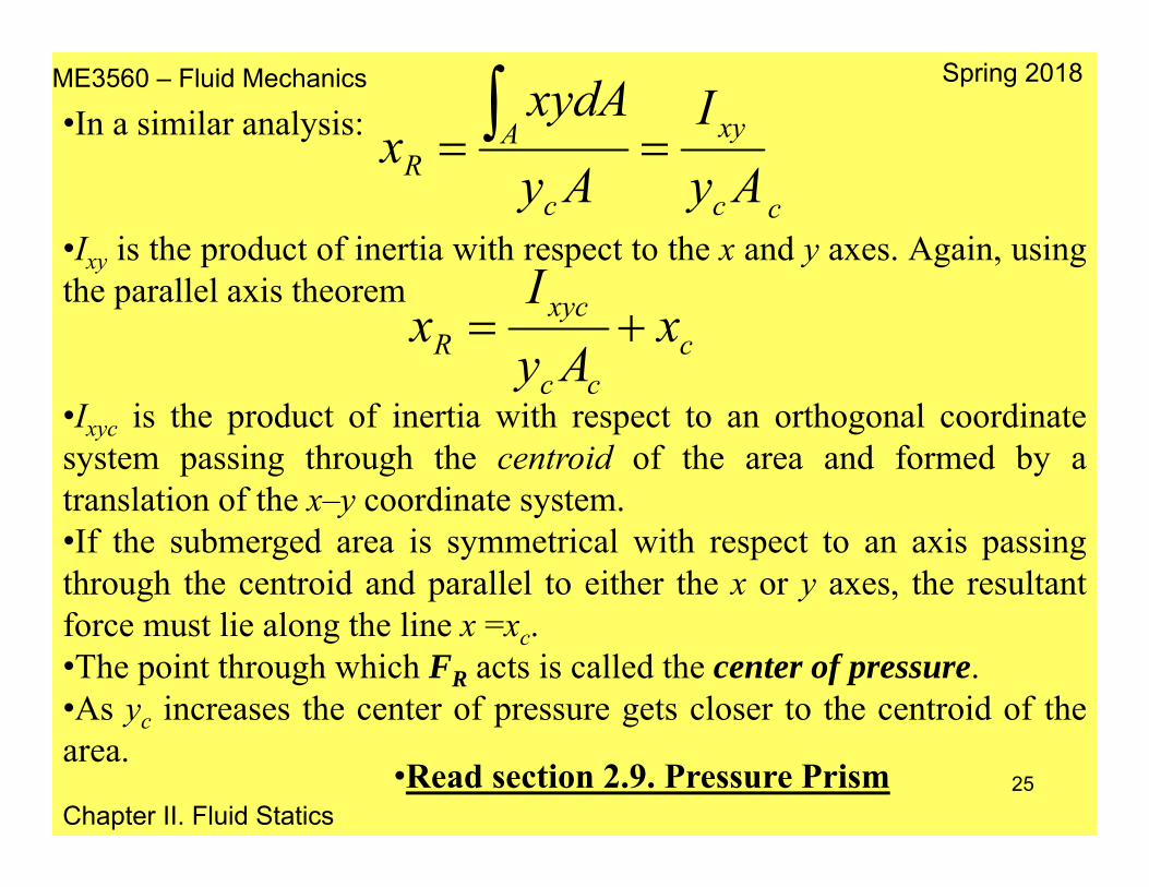
•In a similar analysis:
•Ixy is the product of inertia with respect to the x and y axes. Again, usingthe parallel axis theorem
•Ixyc is the product of inertia with respect to an orthogonal coordinatesystem passing through the centroid of the area and formed by atranslation of the x–y coordinate system.•If the submerged area is symmetrical with respect to an axis passingthrough the centroid and parallel to either the x or y axes, the resultantforce must lie along the line x =xc.•The point through which FR acts is called the center of pressure.•As yc increases the center of pressure gets closer to the centroid of thearea.
cc
xy
c
AR Ay
IAy
xydAx
ccc
xycR x
AyI
x
•Read section 2.9. Pressure Prism
ME3560 – Fluid Mechanics
Chapter II. Fluid Statics
Spring 2018
26
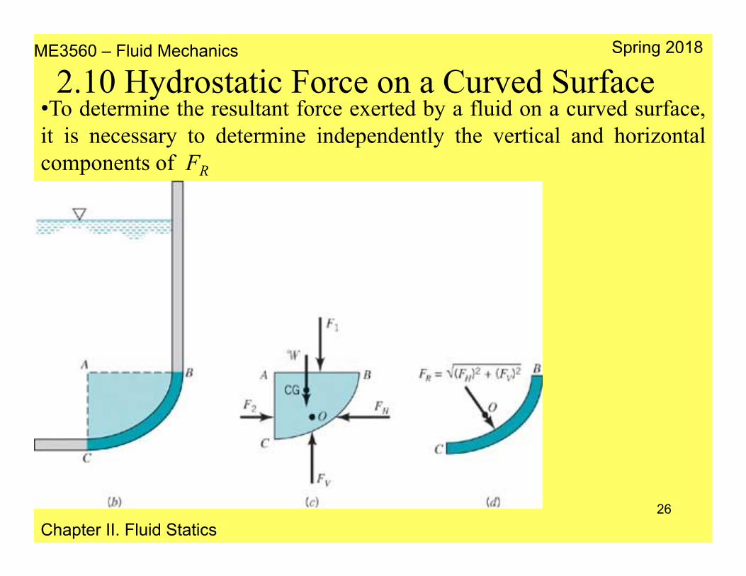
2.10 Hydrostatic Force on a Curved Surface•To determine the resultant force exerted by a fluid on a curved surface,it is necessary to determine independently the vertical and horizontalcomponents of FR

ME3560 – Fluid Mechanics
Chapter II. Fluid Statics
Spring 2018
27
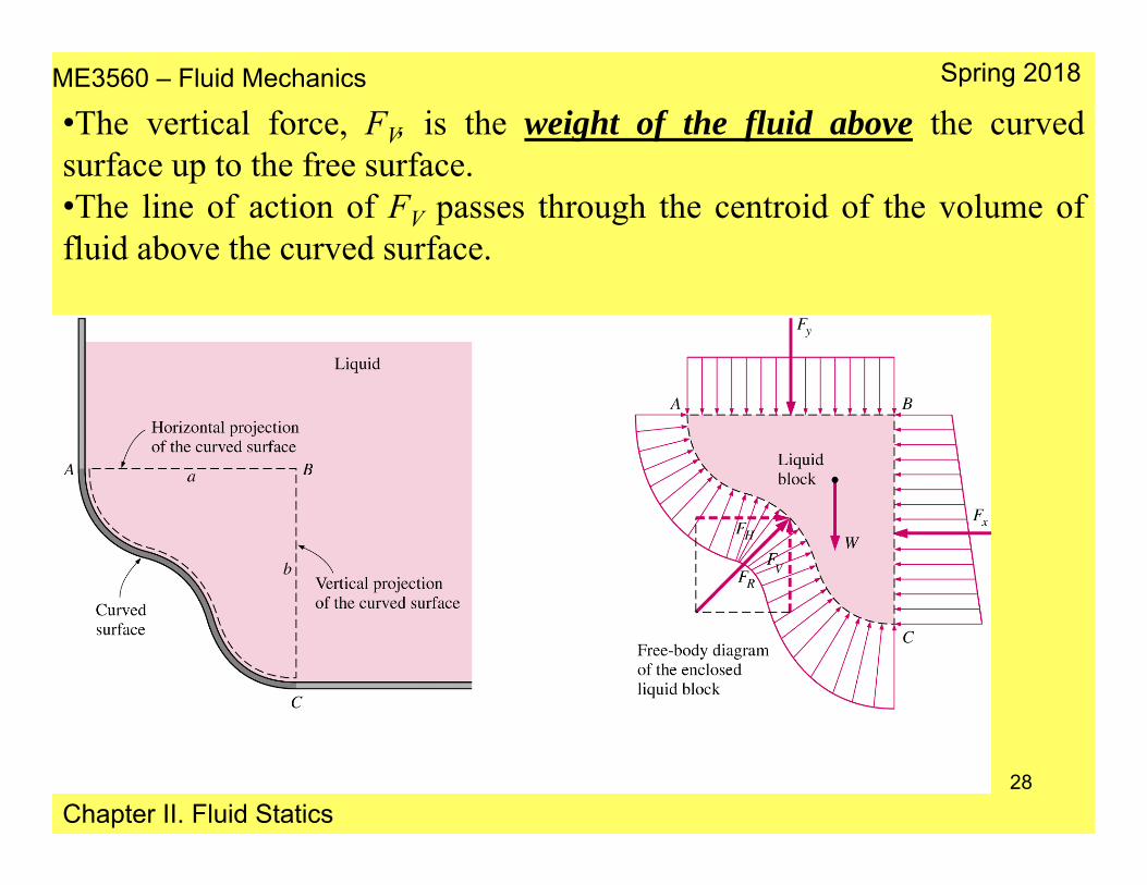
•The horizontal force, FH, is determined by projecting the curved surfaceonto the vertical plane (y–z) and calculating the force that the fluid wouldexert on this imaginary vertical surface.•The point of application of FH corresponds to the location where theforce would act on the imaginary (projection) vertical surface.
ME3560 – Fluid Mechanics
Chapter II. Fluid Statics
Spring 2018
28
•The vertical force, FV, is the weight of the fluid above the curvedsurface up to the free surface.•The line of action of FV passes through the centroid of the volume offluid above the curved surface.

ME3560 – Fluid Mechanics
Chapter II. Fluid Statics
Spring 2018
29
2.11 Buoyancy, Flotation and Stability
•If a stationary body is completely or partially (floating) submerged in afluid, the force exerted by the fluid on the body called buoyant force.•A net upward vertical force results because pressure increases withdepth and the pressure forces acting from below are larger than thepressure forces acting from above.
2.11.1 Archimedes’ Principle

ME3560 – Fluid Mechanics
Chapter II. Fluid Statics
Spring 2018
30
•Consider a flat plate of thickness h submerged in a liquid of density fparallel to the free surface.•The area of the top and bottom surface of the plate is A and its distanceto the free surface is s.•The pressure at the top and bottom surfaces are f gs and f g(s+h).•The hydrostatic force acting on the top surface is Ftop=f gsA, the largerforce Fbottom=fg(s+h)A acts upward on the bottom surface of the plate.•The difference between these two forces is a net upward force(buoyancy force)
gVghAF
gsAAhsgF
FFF
ffB
ffB
topbottomB
)(
ME3560 – Fluid Mechanics
Chapter II. Fluid Statics
Spring 2018
31
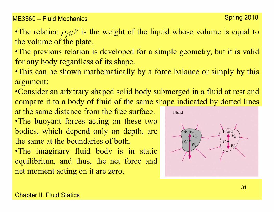
•The relation f gV is the weight of the liquid whose volume is equal tothe volume of the plate.•The previous relation is developed for a simple geometry, but it is validfor any body regardless of its shape.•This can be shown mathematically by a force balance or simply by thisargument:•Consider an arbitrary shaped solid body submerged in a fluid at rest andcompare it to a body of fluid of the same shape indicated by dotted linesat the same distance from the free surface.•The buoyant forces acting on these twobodies, which depend only on depth, arethe same at the boundaries of both.•The imaginary fluid body is in staticequilibrium, and thus, the net force andnet moment acting on it are zero.
ME3560 – Fluid Mechanics
Chapter II. Fluid Statics
Spring 2018
32
•Thus, the upward buoyant force must be equal to the weight of theimaginary fluid body, whose volume is equal to the volume of the solidbody.•Further, the weight and the buoyant force must have the same line ofaction to have a zero moment.•This is known as Archimedes’ Principle:•The buoyant force acting on a body immersed in a fluid is equal tothe weight of the fluid displaced by the body, and it acts upwardthrough the centroid of the displaced volume.
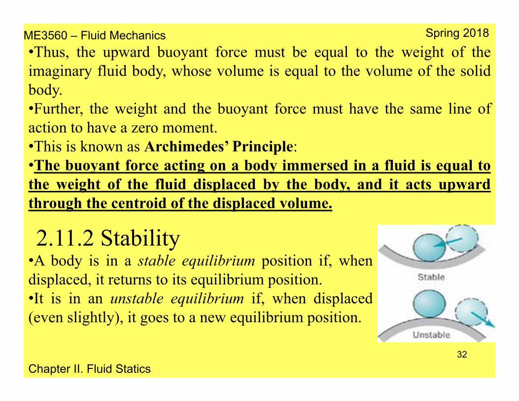
•A body is in a stable equilibrium position if, whendisplaced, it returns to its equilibrium position.•It is in an unstable equilibrium if, when displaced(even slightly), it goes to a new equilibrium position.
2.11.2 Stability

ME3560 – Fluid Mechanics
Chapter II. Fluid Statics
Spring 2018
33
•Stability considerations are particularlyimportant for submerged or floating bodiessince the centers of buoyancy and gravitydo not necessarily coincide.•A small rotation can result in either arestoring or overturning couple.•For a completely submerged body withCG below the center of buoyancy.•A rotation from its equilibrium position will create a restoring coupleformed by the weight, W, and the buoyant force, FB, causing the body torotate back to its original position. Thus, for this configuration the bodyis stable.•The body will be stable as long as the center of gravity falls belowthe center of buoyancy.

ME3560 – Fluid Mechanics
Chapter II. Fluid Statics
Spring 2018
34
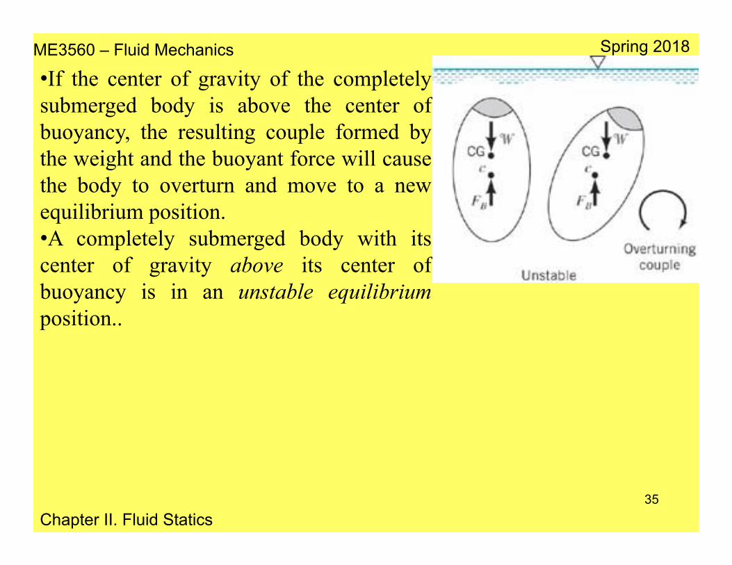
•For the completely submerged body shown, which has a center ofgravity below the center of buoyancy, a rotation from its equilibriumposition will create a restoring couple formed by the weight, W, and thebuoyant force, FB, which causes the body to rotate back to its originalposition. Thus, for this configuration the body is stable. It is to be notedthat the body will be stable as long as the center of gravity falls belowthe center of buoyancy, thus the body is in a stable equilibrium positionwith respect to small rotations. However, as is illustrated in Fig. 2.26, ifthe center of gravity of the completely submerged body is above thecenter of buoyancy, the resulting couple formed by the weight and thebuoyant force will cause the body to overturn and move to a newequilibrium position. Thus, a completely submerged body with its centerof gravity above its center of buoyancy is in an unstable equilibriumposition.
ME3560 – Fluid Mechanics
Chapter II. Fluid Statics
Spring 2018
35
•If the center of gravity of the completelysubmerged body is above the center ofbuoyancy, the resulting couple formed bythe weight and the buoyant force will causethe body to overturn and move to a newequilibrium position.•A completely submerged body with itscenter of gravity above its center ofbuoyancy is in an unstable equilibriumposition..

ME3560 – Fluid Mechanics
Chapter II. Fluid Statics
Spring 2018
36
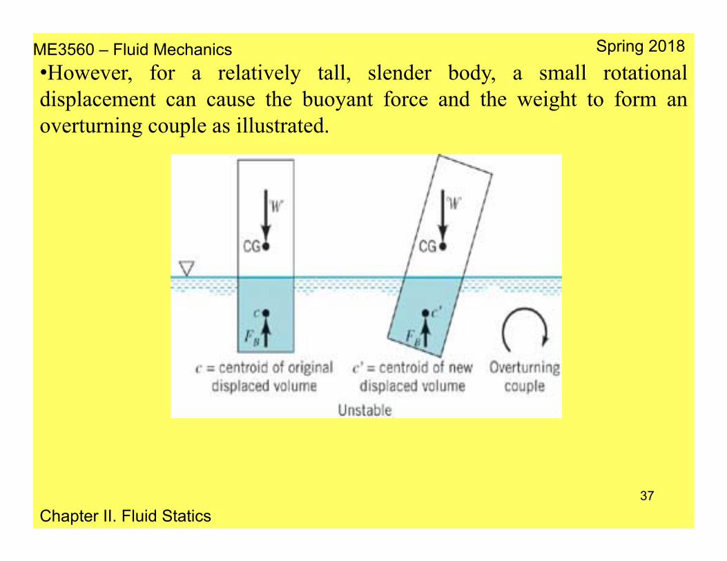
•For floating bodies the stability problem is more complicated.•As the body rotates the location of the center of buoyancy (which passesthrough the centroid of the displaced volume) may change.•A floating body such as a barge that rides low in the water can be stableeven though the center of gravity lies above the center of buoyancy.•This is true since as the body rotates FB shifts to pass through thecentroid of the newly formed displaced volume and combines with W toform a couple which will cause the body to return to its originalequilibrium position.
ME3560 – Fluid Mechanics
Chapter II. Fluid Statics
Spring 2018
37
•However, for a relatively tall, slender body, a small rotationaldisplacement can cause the buoyant force and the weight to form anoverturning couple as illustrated.

ME3560 – Fluid Mechanics
Chapter II. Fluid Statics
Spring 2018
38
•The general equation of motion:•was developed for both fluids at rest and fluids in motion, for situationswhere there were no shearing stresses present. This equation can beexpressed as
•Problems involving fluid motion with no shearing stresses appear whena mass of fluid undergoes rigid-body motion.•For example, if a container of fluid accelerates along a straight path, thefluid will move as a rigid mass (after the initial sloshing motion has diedout) with each particle having the same acceleration. Since there is nodeformation, there will be no shearing stresses. Thus the previousequations apply.
2.12 Pressure Variation in a Fluid with Rigid–Body Motion
akp ˆ
zyx azpa
ypa
xp

ME3560 – Fluid Mechanics
Chapter II. Fluid Statics
Spring 2018
39
•Consider an open container of a liquid that is translating along a straightpath with a constant acceleration a (ax = 0), therefore ∂p/∂x = 0.•In the y and z directions:
•The change in pressure between two closely spaced points located at y,z, and y + dy, z + dz can be expressed as
•Or in terms of the problem studied:
2.12.1 Linear Motion
)( gazp
ayp
z
y
dzzpdy
ypdp
dzagdyadp zy )(

ME3560 – Fluid Mechanics
Chapter II. Fluid Statics
Spring 2018
40
•Along a line of constant pressure (for examplethe free surface), dp = 0, then the slope of this lineis:
z
y
aga
dydz
•Thus, the free surface of the acceleratingmass will be inclined if ay 0.•In addition, all lines of constant pressurewill be parallel to the free surface.•For the case when ay = 0, az ≠ 0 (the massof fluid accelerating in the verticaldirection), the fluid surface will behorizontal with pressure distributiondifferent than hydrostatic, and given by
)( zagdzdp

ME3560 – Fluid Mechanics
Chapter II. Fluid Statics
Spring 2018
41
•After an initial “start-up” transient, a fluid contained in a tank thatrotates with a constant angular velocity ω about an axis will rotate withthe tank as a rigid body.•The acceleration of a fluid particle located at a distance r from the axisof rotation is equal in magnitude to rω2, and the direction of theacceleration is toward the axis of rotation.•The pressure gradient p can be expressed in cylindrical polarcoordinates r, θ, and z as:
•In terms of this coordinate system:•It follows from
•That the eqns. are:
2.12.2 Rigid–Body Rotation
zr ezpep
rerpp ˆˆ1ˆ
0;0;ˆ2 zrr aaera
akp ˆ
zpp
rp r ;0;2
ME3560 – Fluid Mechanics
Chapter II. Fluid Statics
Spring 2018
42
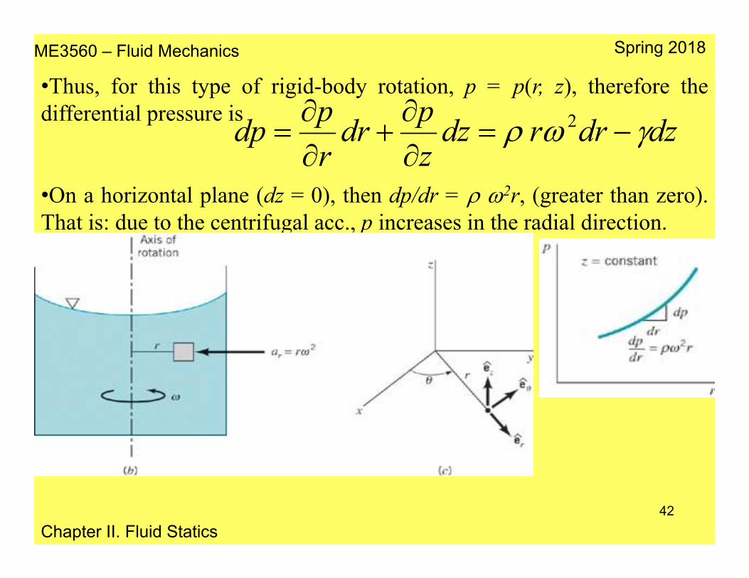
•Thus, for this type of rigid-body rotation, p = p(r, z), therefore thedifferential pressure is
•On a horizontal plane (dz = 0), then dp/dr = 2r, (greater than zero).That is: due to the centrifugal acc., p increases in the radial direction.
dzdrrdzzpdr
rpdp
2

ME3560 – Fluid Mechanics
Chapter II. Fluid Statics
Spring 2018
43
•Along a surface of constant pressure, such as the free surface, dp = 0,
•Integration of this result gives the equation for surfaces of constantpressure as
•This expression reveals that these surfaces of constant pressure areparabolic.
gr
drdzdzdrrdp
22
constant2
22
g
rz

ME3560 – Fluid Mechanics
Chapter II. Fluid Statics
Spring 2018
44
•Integration of•Yields
•The constant of integration can beexpressed in terms of a specifiedpressure at some arbitrary point r0, z0.
•This result shows that the pressurevaries with the distance from the axisof rotation, but at a fixed radius, thepressure varies hydrostatically in thevertical direction.
dzdrrdp 2
constant2
22
2
zrp
dzrdrdp

ME3560 – Fluid Mechanics
Chapter II. Fluid Statics
Spring 2018
45
Read Sections:2.3.2 Compressible Fluid2.6.3 Inclined–Tube Manometer2.9. Pressure Prism

ME3560 – Fluid Mechanics
Chapter II. Fluid Statics
Spring 2018
46