me 113 computer aided engineering...
TRANSCRIPT

ME 113
Computer Aided Engineering
Drawing
Asst.Prof.Dr.Turgut AKYÜREK
Çankaya University, Ankara
Sectioning

Section Views
T.Akyürek 2/128 ME 113 Computer Aided Engineering Drawing – Sectioning
Ordinary multiview drawings may not be enough to fully
explain the inner details of the objects in some cases.
Section views are used in such cases.

Section Views
T.Akyürek 3/128 ME 113 Computer Aided Engineering Drawing – Sectioning
Reel itself Section view of the reel

Section Views
Sections can be used to reveal interior
features of an object that are not easily
represented using hidden lines.
Aims of sectioning are;
– to improve the visualization of new designs,
– to clarify multiview drawings,
– to facilitate the dimensioning of drawings.
T.Akyürek 4/128 ME 113 Computer Aided Engineering Drawing – Sectioning

Section Views
T.Akyürek 5/128 ME 113 Computer Aided Engineering Drawing – Sectioning
A Typical multiview technical drawing shows the right side view in full section and removed section details.

Sectioning Basics
T.Akyürek 6/128 ME 113 Computer Aided Engineering Drawing – Sectioning
Cutting Planes
Imaginary cutting planes used to create section views are passed through the object to reveal interior features.

Sectioning Basics
T.Akyürek 7/128 ME 113 Computer Aided Engineering Drawing – Sectioning
Suppose a
cutting plane
through the top
view, then the
front view would
become a
section view.
Section View Reveals Hidden Features

The cutting plane (section plane)
is represented by section line with
arrows denoting the direction of
view. The portions cut by the
section view are cross-hatched.
Sectioning Basics
T.Akyürek 8/128 ME 113 Computer Aided Engineering Drawing – Sectioning

Sectioning Examples
T.Akyürek 9/128 ME 113 Computer Aided Engineering Drawing – Sectioning
Mechanical assembly of a jet aircraft in section showing how parts
fit and their spatial relationship

Sectioning Examples
T.Akyürek 10/128 ME 113 Computer Aided Engineering Drawing – Sectioning
Bent cap section of a prestressed concreate box girder bridge superstructure

Sectioning Examples
T.Akyürek 11/128 ME 113 Computer Aided Engineering Drawing – Sectioning
Sectioned technical illustration of an internal combustion engine

Suppose that we want to generate the section view of
the object shown below cut by the hatched plane.
Sectioning Steps
T.Akyürek 12/128 ME 113 Computer Aided Engineering Drawing – Sectioning

1. Denote the sectioning plane on a suitable view. For this
case select the top view. Name the sectioning plane by
letters (A-A', or A-A).
Sectioning Steps
T.Akyürek 13/128 ME 113 Computer Aided Engineering Drawing – Sectioning
Top view of the part

2. Draw what you see along the cutting plane and beyond on
the corresponding view (right side view in this case). Hatch
the portions where the cutting plane passes. Label the
section view than (Section A-A' or Section A-A).
Sectioning Steps
T.Akyürek 14/128 ME 113 Computer Aided Engineering Drawing – Sectioning
Section view

Sectioning Basics
T.Akyürek 15/128 ME 113 Computer Aided Engineering Drawing – Sectioning
Treatment of Hidden Lines
Normally, hidden lines are omitted from section views.

Sectioning Basics
T.Akyürek 16/128 ME 113 Computer Aided Engineering Drawing – Sectioning
Optional Use of Hidden Lines
Hidden lines can be shown in section views to eliminate the need for another view.

Sectioning Basics
T.Akyürek 17/128 ME 113 Computer Aided Engineering Drawing – Sectioning
Representing Surfaces and
Edges in Section Views

Not only the portions where
the cutting plane passes
are drawn, but also the
features beyond the cutting
plane are drawn. An
illustrative example is on
the right.
Some Details
T.Akyürek 18/128 ME 113 Computer Aided Engineering Drawing – Sectioning
Correct Incorrect

Ribs, webs and
other thin
features: – A rib or web is a
thin, flat part that acts as a support.
– Ribs, webs, lugs and other thin features are not section lined (crosshatched) when the cutting plane passes parallel to the feature.
Some Details
T.Akyürek 19/128 ME 113 Computer Aided Engineering Drawing – Sectioning
Correct Incorrect

Some Details
(A) True orthographic
projection sometimes yields a
misimpression of objects.
Foreshortening of features such
as holes, lugs, ribs, spokes,
and arms should be avoided.
(B) Recommended practice is
to rotate the feature into the
plane of projection to yield an
aligned view. Here both the
hole and the rib have been
rotated.
T.Akyürek 20/128 ME 113 Computer Aided Engineering Drawing – Sectioning

Some Details
When shown in section
views (case A), the web is
sectioned to indicate the
continuity of the material
throughout the
circumference of the wheel.
When shown in section
views (case B), spokes are
not sectioned to indicate
gaps around the
circumference.
T.Akyürek 21/128 ME 113 Computer Aided Engineering Drawing – Sectioning

Some Details
T.Akyürek 22/128 ME 113 Computer Aided Engineering Drawing – Sectioning

CAD Technique
T.Akyürek 23/128 ME 113 Computer Aided Engineering Drawing – Sectioning
Defining a Cutting Plane on a CAD Model
A 3-D CAD solid model can be sectioned by positioning a cutting plane relative to the object.
Sectioned CAD Model
The object is automatically cut along the cutting plane to produce a section view.

Visualization of Section Views
T.Akyürek 24/128 ME 113 Computer Aided Engineering Drawing – Sectioning
Visualization of a Section View
A section view is created by drawing the outline of the surfaces cut by the cutting plane. Details then are added to show surfaces behind the cutting plane, such as the back of counterbored hole.
Counter bore
Through hole

Visualization of Section Views
T.Akyürek 25/128 ME 113 Computer Aided Engineering Drawing – Sectioning
Labeling Features for Visualization
The section view is created by passing an imaginary cutting plane vertically through the object. Corners are labeled to assist in the visualization of the orthographic section view.
Counter bore
Through hole

Cutting Plane Lines
T.Akyürek 26/128 ME 113 Computer Aided Engineering Drawing – Sectioning
Placement of Cutting Plane Lines
The cutting plane line is placed in the view where the cutting plane appears on edge.

Cutting Plane Lines
T.Akyürek 27/128 ME 113 Computer Aided Engineering Drawing – Sectioning
Standard Cutting Plane Linestyles
Standard cutting plane linestyles are thick lines terminated with arrows.

Cutting Plane Lines
T.Akyürek 28/128 ME 113 Computer Aided Engineering Drawing – Sectioning
Horizontal Section View
A horizontal section view is one in which the cutting plane is on adge in the front view and the top view is sectioned.

Cutting Plane Lines
T.Akyürek 29/128 ME 113 Computer Aided Engineering Drawing – Sectioning
Profile Section View
A profie section view is one in which the cutting plane is on edge in the front and top views and the profile view is sectioned.

Cutting Plane Lines
T.Akyürek 30/128 ME 113 Computer Aided Engineering Drawing – Sectioning
Multiple Section Views
Multiple section views can be created on a single multiview drawing. This example shows horizontal and profile section views. Note that each section view is labeled to correspond to its cutting plane line.

Section (Cross-Hatch) Lines
T.Akyürek 31/128 ME 113 Computer Aided Engineering Drawing – Sectioning
ANSI Standard Section Lines for Various
Materials
General
Purpose
Section
Line

Section (Cross-Hatch) Lines
T.Akyürek 32/128 ME 113 Computer Aided Engineering Drawing – Sectioning
Examples of Good and Poor
Section Lining Techniques

Section (Cross-Hatch) Lines
T.Akyürek 33/128 ME 113 Computer Aided Engineering Drawing – Sectioning
Section Line Placement
Avoid placing section lines parallel or perpendicular to visible lines.

Section (Cross-Hatch) Lines
T.Akyürek 34/128 ME 113 Computer Aided Engineering Drawing – Sectioning
Notes in Section-Lined Areas
Section lines are omitted around notes and dimensions.

Section (Cross-Hatch) Lines
T.Akyürek 35/128 ME 113 Computer Aided Engineering Drawing – Sectioning
Outline Sectioning
Outline sectioning is used on large areas.

Section (Cross-Hatch) Lines
T.Akyürek 36/128 ME 113 Computer Aided Engineering Drawing – Sectioning
Thin Parts in Section
Thin parts in section are represented without section lines (ASME Y14.2M-1992).

Section View Types Full section
Half section
Offset section
Aligned section
Revolved (Rotated)
section
Broken-out section
Removed section
Assembly section
Auxiliary Section
T.Akyürek 37/128 ME 113 Computer Aided Engineering Drawing – Sectioning

The object is cut thoroughly.
Full Section
T.Akyürek 38/128 ME 113 Computer Aided Engineering Drawing – Sectioning

Full Section
T.Akyürek 39/128 ME 113 Computer Aided Engineering Drawing – Sectioning

Creating a Full-Section View
T.Akyürek 40/128 ME 113 Computer Aided Engineering Drawing – Sectioning

Half sections are used with symmetrical parts and with
cylinders, in particular as shown in the figures.
Half Section
T.Akyürek 41/128 ME 113 Computer Aided Engineering Drawing – Sectioning
Half Section
A half-section view is created by passing a cutting plane halfway through the object.

Half Section
T.Akyürek 42/128 ME 113 Computer Aided Engineering Drawing – Sectioning

Offset Section
T.Akyürek 43/128 ME 113 Computer Aided Engineering Drawing – Sectioning
Offset Section
An offset-section view is created by bending the cutting plane at 90-degree angles to pass through important features.

Offset Section
T.Akyürek 44/128 ME 113 Computer Aided Engineering Drawing – Sectioning
Multiple Offset Sections
Multiple offset-section views use labels for identification.

Offset Section
T.Akyürek 45/128 ME 113 Computer Aided Engineering Drawing – Sectioning

Offset Section
T.Akyürek 46/128 ME 113 Computer Aided Engineering Drawing – Sectioning

Aligned Section
The filter cover has tri-
symmetric features
that are equally spaced
around the circular
body. For this case, an
aligned section
technique is
appropriate. An
angular cutting plane
cuts through two of the
three slots as shown
on the figure.
T.Akyürek 47/128 ME 113 Computer Aided Engineering Drawing – Sectioning

Aligned Section
T.Akyürek 48/128 ME 113 Computer Aided Engineering Drawing – Sectioning
Aligned Section
T.Akyürek 49/128 ME 113 Computer Aided Engineering Drawing – Sectioning
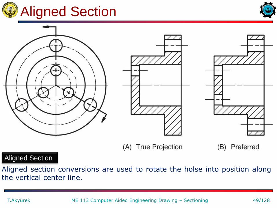
Aligned Section
Aligned section conversions are used to rotate the holse into position along the vertical center line.

Aligned Section
T.Akyürek 50/128 ME 113 Computer Aided Engineering Drawing – Sectioning
Aligning Spokes
Aligning spokes in section views is the conventional method of representation.

Aligned Section
T.Akyürek 51/128 ME 113 Computer Aided Engineering Drawing – Sectioning
Aligning Lugs
Aligning lugs in section views is the conventional method of representation.

Aligned Section
T.Akyürek 52/128 ME 113 Computer Aided Engineering Drawing – Sectioning
Aligning Ribs
Aligning ribs in section views is the conventional method of representation.

Rotated (Revolved) Section
Imaginary slices of this
chisel are taken
perpendicular (at right
angles) to the view shown.
The slices are then rotated
90º in place where the "slice"
was cut.
If the revolved section does
not fit within the edges of the
cut surface, break lines are
used to show the section, as
shown on the far left section
of this chisel drawing.
T.Akyürek 53/128 ME 113 Computer Aided Engineering Drawing – Sectioning

Rotated (Revolved) Section
T.Akyürek 54/128 ME 113 Computer Aided Engineering Drawing – Sectioning
Revolved (Rotated) Section
A revolved-section view is created by passing a cutting plane through the object, then revolving the cross section 90 degrees.

A broken-out section view is created by breaking off
part of the object to reveal interior features.
Broken-out Section
T.Akyürek 55/128 ME 113 Computer Aided Engineering Drawing – Sectioning
Broken-Out Section
A broken-out section view is created by breaking off part of the object to reveal interior features.

Removed Section
A removed section is
the same as a revolved
section, except that the
perpendicular "slice" is
"removed" to another
area of the drawing.
Cutting-plane lines and
the corresponding
removed sections
are labeled with UPPER
CASE letters in double
alphabetical order:
AA, BB, CC, etc.
T.Akyürek 56/128 ME 113 Computer Aided Engineering Drawing – Sectioning

Removed Section
T.Akyürek 57/128 ME 113 Computer Aided Engineering Drawing – Sectioning
Removed Section
A removed section view is created by making a cross section, then moving it to an area adjacent to the view.

Removed Section
T.Akyürek 58/128 ME 113 Computer Aided Engineering Drawing – Sectioning
Multiple Removed-Section
Views of a Connecting
Rod Identified with Labels

Removed Section
T.Akyürek 59/128 ME 113 Computer Aided Engineering Drawing – Sectioning
Scaled-Section View
A scaled removed section view is placed at any convenient location and labeled with the scale.

Removed Section
T.Akyürek 60/128 ME 113 Computer Aided Engineering Drawing – Sectioning
Aligning Removed-Section Views
In one technique, the removed-section view is aligned along center lines adjacent to the regular view.

Assembly Section
T.Akyürek 61/128 ME 113 Computer Aided Engineering Drawing – Sectioning
Assembly section views are typically full or half sections of multiple assembled parts.

Assembly Section
T.Akyürek 62/128 ME 113 Computer Aided Engineering Drawing – Sectioning

Assembly Section
In addition to thin structural
features, parts not sectioned
also include standard
mechanical elements such as
shafts, bolts, screws, nuts,
rivets, keys, pins, bearings
(roller or ball), and gear teeth.
Here the shaft, bolts, and
nuts of the assembly are not
sectioned even though they
are cut by the cutting plane.
T.Akyürek 63/128 ME 113 Computer Aided Engineering Drawing – Sectioning

Assembly Section
T.Akyürek 64/128 ME 113 Computer Aided Engineering Drawing – Sectioning
Standard Parts not Section Lined
Standard parts, such as fasteners and shafts, are not section lined in assembly sections, even if they are cut by the cutting plane.

Assembly Section
T.Akyürek 65/128 ME 113 Computer Aided Engineering Drawing – Sectioning
Section Lining Adjacent Parts
Adjacent parts in an assembly section are section lined at different angles so that individual parts can be more easily identified.

Assembly Section
T.Akyürek 66/128 ME 113 Computer Aided Engineering Drawing – Sectioning
Translucency of a CAD Model
With a 3-D CAD model, translucency can be used instaed of cutting planes to reveal interior features.

Auxiliary Section
T.Akyürek 67/128 ME 113 Computer Aided Engineering Drawing – Sectioning
A Full Auxiliary Section View

Auxiliary Section
T.Akyürek 68/128 ME 113 Computer Aided Engineering Drawing – Sectioning
A Partial Auxiliary Section View
Parts of the object appearing behind the auxiliary section view sometimes are not drawn, to improve the clarity of the drawing.

Conventional Breaks
T.Akyürek 69/128 ME 113 Computer Aided Engineering Drawing – Sectioning
Examples of Conventional Break Symbols Used for
Various Materials

Sectioning in AutoCAD
T.Akyürek 70/128 ME 113 Computer Aided Engineering Drawing – Sectioning

Sectioning in AutoCAD
T.Akyürek 71/128 ME 113 Computer Aided Engineering Drawing – Sectioning
If we have more than one part in our view, we will need to make sure that it stands out. Here we have the same part, but with another piece placed inside it.

Drawing Section Views in AutoCAD
T.Akyürek 72/128 ME 113 Computer Aided Engineering Drawing – Sectioning
Begin by drawing the part below. You do not need to draw the Isometric view, it is just for reference.

Drawing Section Views in AutoCAD
T.Akyürek 73/128 ME 113 Computer Aided Engineering Drawing – Sectioning
To draw the "Cutting Plane" that marks the section, draw a line and then use the leader command to make the arrows. Add text for the "A"s. Copy the related view. Change the hidden lines. Remove the lines that lost edge position. Section view before hatching:

From “draw” pull-down menu
choose hatch or click the hatch
icon.
You will get Boundary hatch
dialog box.
Select a hatching pattern
(Hatching pattern should be
the same for the same
material).
Use ANSI31 as a pattern for
sections. You can choose 0.5,
0.75 or 1 as a scale depending
of your drawing.
Select the object to hatch.
Hatching in AutoCAD
T.Akyürek 74/128 ME 113 Computer Aided Engineering Drawing – Sectioning

Drawing Section Views in AutoCAD
Start the Hatch command and pick in the spots shown below.
Pick all the three areas at the same time so that the hatch
creates one object instead of three.
T.Akyürek 75/128 ME 113 Computer Aided Engineering Drawing – Sectioning

Drawing Section Views in AutoCAD
T.Akyürek 76/128 ME 113 Computer Aided Engineering Drawing – Sectioning

Section Views with 3-D CAD
T.Akyürek 77/128 ME 113 Computer Aided Engineering Drawing – Sectioning
A Section View Created of
a 3-D CAD Model

Section View Exercise 8_1.dwg
T.Akyürek 78/128 ME 113 Computer Aided Engineering Drawing – Isometric Drawing
Generate the section
view A-A'
Full Section

Section View Exercise 8_1.dwg
T.Akyürek 79/128 ME 113 Computer Aided Engineering Drawing – Sectioning
Full Section

Section View Exercise 8_2.dwg
T.Akyürek 80/128 ME 113 Computer Aided Engineering Drawing – Isometric Drawing
Generate the section
view A-A'
Be careful on the
direction of viewing.
Full Section

Section View Exercise 8_2.dwg
T.Akyürek 81/128 ME 113 Computer Aided Engineering Drawing – Isometric Drawing
Full Section

Section View Exercise 8_3.dwg
T.Akyürek 82/128 ME 113 Computer Aided Engineering Drawing – Isometric Drawing
Generate
the section
view A-A'
Full Section

Section View Exercise 8_3.dwg
T.Akyürek 83/128 ME 113 Computer Aided Engineering Drawing – Isometric Drawing
Full Section

Section View Exercise 8_4.dwg
T.Akyürek 84/128 ME 113 Computer Aided Engineering Drawing – Sectioning
Full Section

Section View Exercise 8_4.dwg
T.Akyürek 85/128 ME 113 Computer Aided Engineering Drawing – Sectioning
Full Section

Section View Exercise 8_5.dwg
T.Akyürek 86/128 ME 113 Computer Aided Engineering Drawing – Sectioning
Full Section

Section View Exercise 8_5.dwg
T.Akyürek 87/128 ME 113 Computer Aided Engineering Drawing – Sectioning
Full Section

Section View Exercise 8_6.dwg
T.Akyürek 88/128 ME 113 Computer Aided Engineering Drawing – Sectioning
Full Section

Section View Exercise 8_6.dwg
T.Akyürek 89/128 ME 113 Computer Aided Engineering Drawing – Sectioning
Full Section

Section View Exercise 8_7.dwg
T.Akyürek 90/128 ME 113 Computer Aided Engineering Drawing – Sectioning
Full Section

Section View Exercise 8_7.dwg
T.Akyürek 91/128 ME 113 Computer Aided Engineering Drawing – Sectioning
Full Section

Section View Exercise 8_8.dwg
T.Akyürek 92/128 ME 113 Computer Aided Engineering Drawing – Sectioning
Full Section

Section View Exercise 8_8.dwg
T.Akyürek 93/128 ME 113 Computer Aided Engineering Drawing – Sectioning
Full Section

Section View Exercise 8_9.dwg
T.Akyürek 94/128 ME 113 Computer Aided Engineering Drawing – Sectioning
Offset Section

Section View Exercise 8_9.dwg
T.Akyürek 95/128 ME 113 Computer Aided Engineering Drawing – Sectioning
Offset Section

Section View Exercise 8_10.dwg
T.Akyürek 96/128 ME 113 Computer Aided Engineering Drawing – Sectioning
Full Section

Section View Exercise 8_10.dwg
T.Akyürek 97/128 ME 113 Computer Aided Engineering Drawing – Sectioning
Full Section

Section View Exercise 8_11.dwg Draw the multi view. Then, generate
the section view on the front view.
T.Akyürek 98/128 ME 113 Computer Aided Engineering Drawing – Sectioning
Full Section

Section View Exercise 8_11.dwg
T.Akyürek 99/128 ME 113 Computer Aided Engineering Drawing – Sectioning
Full Section

Section View Exercise 8_12.dwg
T.Akyürek 100/128 ME 113 Computer Aided Engineering Drawing – Sectioning
Draw the multi view. Then, generate the section view on the side view.
Full Section

Section View Exercise 8_12.dwg
T.Akyürek 101/128 ME 113 Computer Aided Engineering Drawing – Sectioning
Full Section

Section View Exercise 8_13.dwg
T.Akyürek 102/128 ME 113 Computer Aided Engineering Drawing – Sectioning
Full Section

Section View Exercise 8_13.dwg
T.Akyürek 103/128 ME 113 Computer Aided Engineering Drawing – Sectioning
Full Section

Section View Exercise 8_14.dwg
T.Akyürek 104/128 ME 113 Computer Aided Engineering Drawing – Sectioning
Aligned Section

Section View Exercise 8_14.dwg
T.Akyürek 105/128 ME 113 Computer Aided Engineering Drawing – Sectioning
Aligned Section

Section View Exercise 8_15.dwg
T.Akyürek 106/128 ME 113 Computer Aided Engineering Drawing – Sectioning
Aligned Section

Section View Exercise 8_15.dwg
T.Akyürek 107/128 ME 113 Computer Aided Engineering Drawing – Sectioning
Aligned Section

Section View Exercise 8_16.dwg
T.Akyürek 108/128 ME 113 Computer Aided Engineering Drawing – Sectioning
Half Section

Section View Exercise 8_16.dwg
T.Akyürek 109/128 ME 113 Computer Aided Engineering Drawing – Sectioning
Half Section

Section View Exercise 8_17.dwg
T.Akyürek 110/128 ME 113 Computer Aided Engineering Drawing – Sectioning
Aligned Section

Section View Exercise 8_17.dwg
T.Akyürek 111/128 ME 113 Computer Aided Engineering Drawing – Sectioning
Aligned Section

Section View Exercise 8_18.dwg
T.Akyürek 112/128 ME 113 Computer Aided Engineering Drawing – Sectioning
Full Section

Section View Exercise 8_18.dwg
T.Akyürek 113/128 ME 113 Computer Aided Engineering Drawing – Sectioning
Full Section

Section View Exercise 8_19.dwg
T.Akyürek 114/128 ME 113 Computer Aided Engineering Drawing – Sectioning
Full Section

Section View Exercise 8_19.dwg
T.Akyürek 115/128 ME 113 Computer Aided Engineering Drawing – Sectioning
Full Section

Section View Exercise 8_20.dwg
T.Akyürek 116/128 ME 113 Computer Aided Engineering Drawing – Sectioning
Full Section

Section View Exercise 8_20.dwg
T.Akyürek 117/128 ME 113 Computer Aided Engineering Drawing – Sectioning
Full Section

Problem 8.1 (Figure 8.53 (C))
T.Akyürek 118/128 ME 113 Computer Aided Engineering Drawing – Sectioning
Sketch, or draw with CAD, full-section views. Each grid is 0.25’’ or 10 mm.

Problem 8.2 (Figure 8.54 (D))
T.Akyürek 119/128 ME 113 Computer Aided Engineering Drawing – Sectioning
Sketch, or draw with CAD, offset-section views. Each grid is 0.25’’ or 10 mm.

Problem 8.3 (Figure 8.55(B))
T.Akyürek 120/128 ME 113 Computer Aided Engineering Drawing – Sectioning
Sketch, or draw with CAD, half-section views. Each grid is 0.25’’ or 10 mm.

Problem 8.5 (Figure 8.57 (5))
T.Akyürek 121/128 ME 113 Computer Aided Engineering Drawing – Sectioning
Sketch, or draw with CAD, the views with sections as indicated by the cutting plane lines. Each grid is 0.25’’ or 10 mm.

Problem 8.5 (Figure 8.57 (18))
T.Akyürek 122/128 ME 113 Computer Aided Engineering Drawing – Sectioning
Sketch, or draw with CAD, the views with sections as indicated by the cutting plane lines. Each grid is 0.25’’ or 10 mm.

Problem 8.6 (Figure 8.59) Counter Block
T.Akyürek 123/128 ME 113 Computer Aided Engineering Drawing – Sectioning
Sketch, or draw with CAD, then create the necessary views, including a section view, or create a 3-D model.

Problem 8.6 (Figure 8.63) Taper Collar
T.Akyürek 124/128 ME 113 Computer Aided Engineering Drawing – Sectioning
Sketch, or draw with CAD, then create the necessary views, including a section view, or create a 3-D model.

Problem 8.6 (Figure 8.65) Heavy-Duty V-Pulley
T.Akyürek 125/128 ME 113 Computer Aided Engineering Drawing – Sectioning
Sketch, or draw with CAD, then create the necessary views, including a section view, or create a 3-D model.
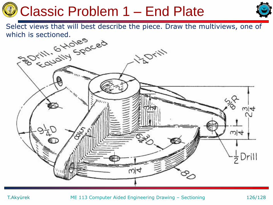
Classic Problem 1 – End Plate
T.Akyürek 126/128 ME 113 Computer Aided Engineering Drawing – Sectioning
Select views that will best describe the piece. Draw the multiviews, one of which is sectioned.

Figure 8.70 – Roller-Model TX
T.Akyürek 127/128 ME 113 Computer Aided Engineering Drawing – Sectioning
Construct 3-D solid part, then create the necessary views, including a section view.

English – Turkish Dictionary
section kesit sectioning Kesit alma Section view Kesit görünüş
Inner details İç ayrıntılar Reel makara Cutting plane Kesme düzlemi
hatching tarama Cross-hatching Kesit tarama hatched taralı
web support destek lug Sap, kulp
spoke Cant teli (kolu) Full section Tam kesit Half section Yarım kesit
Offset section Çıkıntılı kesit Aligned section Hizalı kesit Rotated section (Ekseni etrafında)
döndürülmüş kesit
Revolved
section
(bir eksen etrafında)
döndürülümüş kesit
Assembly section Montaj kesiti nut somun
bolt civata rivet perçin screw vida
key kama pin pim bearing (mil) yatak, burç
gear dişli İnterior features İç özellikler
T.Akyürek 128/128 ME 113 Computer Aided Engineering Drawing – Sectioning