me 102b – final project december 8, 2020 line follower robot
TRANSCRIPT
ME 102B – Final Project
Jeremiah F Teofil
December 8, 2020
Line Follower Robot
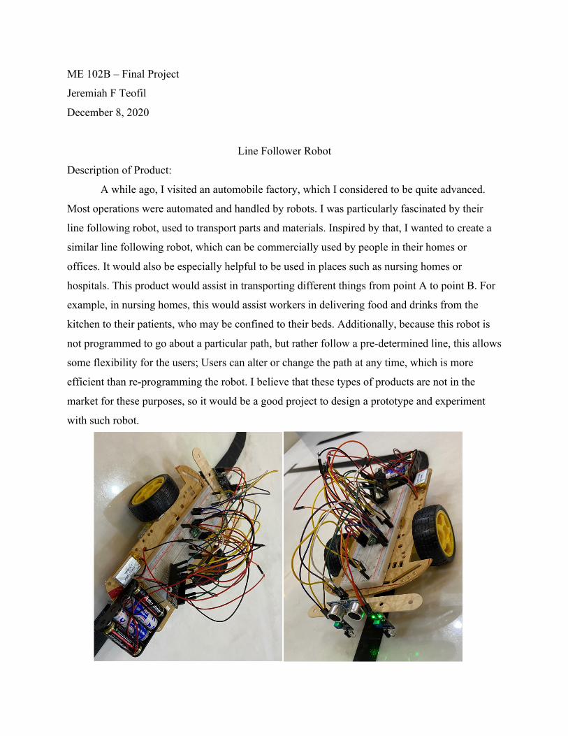
Description of Product:
A while ago, I visited an automobile factory, which I considered to be quite advanced.
Most operations were automated and handled by robots. I was particularly fascinated by their
line following robot, used to transport parts and materials. Inspired by that, I wanted to create a
similar line following robot, which can be commercially used by people in their homes or
offices. It would also be especially helpful to be used in places such as nursing homes or
hospitals. This product would assist in transporting different things from point A to point B. For
example, in nursing homes, this would assist workers in delivering food and drinks from the
kitchen to their patients, who may be confined to their beds. Additionally, because this robot is
not programmed to go about a particular path, but rather follow a pre-determined line, this allows
some flexibility for the users; Users can alter or change the path at any time, which is more
efficient than re-programming the robot. I believe that these types of products are not in the
market for these purposes, so it would be a good project to design a prototype and experiment
with such robot.
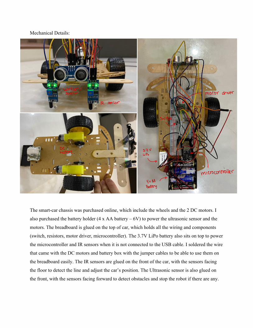
Mechanical Details:
The smart-car chassis was purchased online, which include the wheels and the 2 DC motors. I
also purchased the battery holder (4 x AA battery – 6V) to power the ultrasonic sensor and the
motors. The breadboard is glued on the top of car, which holds all the wiring and components
(switch, resistors, motor driver, microcontroller). The 3.7V LiPo battery also sits on top to power
the microcontroller and IR sensors when it is not connected to the USB cable. I soldered the wire
that came with the DC motors and battery box with the jumper cables to be able to use them on
the breadboard easily. The IR sensors are glued on the front of the car, with the sensors facing
the floor to detect the line and adjust the car’s position. The Ultrasonic sensor is also glued on
the front, with the sensors facing forward to detect obstacles and stop the robot if there are any.
ultrasonicsensor motor driver
IR sensor b
switch
77
DC3.7 V
MotorsLito
←
77
microcontroller>
4xAABattery

Circuit:
This project does not go too complicated with the functions and may not implement every
aspect of motor control introduced in this class, but I had the chance to work with new
components: (1) IR sensor and (2) Ultrasonic sensor
(1) IR Sensor: for the IR sensor, I went ahead and bought 2 pieces at a relatively cheap
price online since it was not included in our lab kit. The component works for 3.3-5V
DC supply. This sensor is the primary component that will keep the robot on track.
Specifically, the IR sensor will detect white (floor) and black (line) differently; it
gives a high (1) signal when it detects the line, and low (0) when it detects the floor.
(2) Ultrasonic Sensor: for the ultrasonic sensor, it was included in our lab kit – HC-SR04
Ultrasonic Sonar Distance Sensor. Because this component runs on 5V, and 5V
power supply included is not a battery, I went ahead and also purchased a battery
holder (4 x AA battery – 6V) to run the sensor. This sensor is responsible for obstacle
detection, which stops the robot.
In addition to these components, I also bought a smart-car chassis along with wheels and 2 DC
motors to run the wheels. These parts were relatively cheap as well. The battery holder (4 x AA
battery – 6V) will also be used to run the motors. I had to solder the jumper cables to the wire
that came along with the DC motors and battery holder to be able to use them with the
breadboard. I also used the
switch (which was used in
earlier assignments) to
switch the robot between
idle and running state, and
also the 3.7V LiPo battery
included in the lab kit to
power the microcontroller
when disconnected from
the USB cable.

Finite State Machine:
The behavior of this robot is relatively simple. It always starts on idle (off). When the
switch is pressed, it will move forward. There are 2 IR sensors attached on the front of the robot
(on the left and right). When the left IR sensor detects the line, it will turn left. Similarly, when
the right IR sensor detects the line, it will turn right. When both IR sensors detects the line, it
means that the robot has reached the end, and returns to the idle state. There is also an Ultrasonic
sensor on the front of the robot for obstacle detection. When it detects an obstacle, it stops the
motor for as long as the obstacle is still present. (Code on the last page)
Further Improvements: This product has lots of flaws. One thing I noticed which sometimes make the robot to go out of path is the fact that the robot moves relatively fast. However, setting the speed to be lower (by reducing PWM), the duty cycle does not provide enough power to start turning the wheels. Also, the robot struggles to make sharp turns, which is why the path are rounded along the corners. Sometimes, too, the IR sensor gives a false signal, causing the robot to turn in a certain direction and go out of path. By improving the code, using better sensors, and adding more components, the movement of the robot can be much smoother and follows the path better or even detects the upcoming path and anticipate the direction. Note on the video: For some reason, the 3.7V LiPo battery is causing the sensors to not work properly. Using the USB cable gives a much better result after a few runs, which is why I used the USB cable instead of the battery in the video

Code: #include <NewPing.h> #define lefts 39 #define rights 36 #define Button_Pin 32 int trigPin = 23; // Trigger int echoPin = 15; // Echo long duration; long cm; int T = 7; NewPing sonar(trigPin, echoPin, 200); long distance; #define MotorA_Pin0 17 #define MotorA_Pin1 16 #define MotorB_Pin0 12 #define MotorB_Pin1 13 #define freq 5000 #define ledChannel1 1 #define ledChannel2 2 #define ledChannel3 3 #define ledChannel4 4 #define resolution 8 #define Debounce 200 boolean state = 0; volatile boolean buttonPressEvent = false; volatile int buttonTimer = 0; volatile int buttonTimer_Last = 0; volatile int currentmillis = 0; volatile int lastmillis = 0; void setup() { pinMode (Button_Pin, INPUT); pinMode (trigPin, OUTPUT); // Sets the trigPin as an OUTPUT pinMode (echoPin, INPUT); // Sets the echoPin as an INPUT pinMode (MotorA_Pin0, OUTPUT); pinMode (MotorA_Pin1, OUTPUT); pinMode (MotorB_Pin0, OUTPUT); pinMode (MotorB_Pin1, OUTPUT); pinMode (lefts,INPUT); pinMode (rights,INPUT); attachInterrupt(digitalPinToInterrupt(Button_Pin), buttonIsPressed, FALLING); ledcSetup(ledChannel1, freq, resolution); ledcSetup(ledChannel2, freq, resolution); ledcSetup(ledChannel3, freq, resolution); ledcSetup(ledChannel4, freq, resolution); ledcAttachPin(MotorA_Pin0, ledChannel1); ledcAttachPin(MotorA_Pin1, ledChannel2); ledcAttachPin(MotorB_Pin0, ledChannel3); ledcAttachPin(MotorB_Pin1, ledChannel4); ledcWrite(ledChannel1, 0); ledcWrite(ledChannel2, 0); ledcWrite(ledChannel3, 0); ledcWrite(ledChannel4, 0); Serial.begin(9600); } void loop() { switch (state) { case 0:

ledcWrite(ledChannel1, 0); ledcWrite(ledChannel2, 0); ledcWrite(ledChannel3, 0); ledcWrite(ledChannel4, 0); if (buttonPressEvent == true) { state = 1; buttonPressEvent = false; } break; case 1: distance = sonar.ping_cm(); Serial.println(distance); if(digitalRead(lefts) == 0 && digitalRead(rights) == 0){ ledcWrite(ledChannel1, 0); ledcWrite(ledChannel2, 200); ledcWrite(ledChannel3, 200); ledcWrite(ledChannel4, 0); } if(digitalRead(lefts) == 0 && digitalRead(rights) == 1){ ledcWrite(ledChannel1, 180); ledcWrite(ledChannel2, 0); ledcWrite(ledChannel3, 200); ledcWrite(ledChannel4, 0); } if(digitalRead(lefts) == 1 && digitalRead(rights) == 0){ ledcWrite(ledChannel1, 0); ledcWrite(ledChannel2, 200); ledcWrite(ledChannel3, 0); ledcWrite(ledChannel4, 180); } if(digitalRead(lefts) == 1 && digitalRead(rights) == 1){ state = 0; } if(distance > 1 && distance < 10){ ledcWrite(ledChannel1, 0); ledcWrite(ledChannel2, 0); ledcWrite(ledChannel3, 0); ledcWrite(ledChannel4, 0); } if (buttonPressEvent == true) { state = 0; buttonPressEvent = false; } } } void buttonIsPressed() { buttonTimer = millis(); if (buttonTimer - buttonTimer_Last > Debounce) { buttonPressEvent = true; buttonTimer_Last = buttonTimer; } }