mdg 41 review - gary nauer
TRANSCRIPT

1
MINING DESIGN GUIDELINE | MDG 41
Guideline for fluid power system safety at mines
Comments close 31 October 2015. Comments should be forward to: [email protected]
2
MINING DESIGN GUIDELINE | MDG 41
The guide for fluid power systems safety at mines MDG41 has undergone an update in line with WHS requirements and industry feedback. It focuses on risk management & mitigation controls to be considered, along with competency and operational guidance. MDG41 now also incorporates links to other relevant data and historical incident reporting along with exposure frequency for more meaningful Risk Assessments.

3
MINING DESIGN GUIDELINE | MDG 41
This document provides an industry benchmark for engineering standards and fit-for-purpose equipment. This document was compiled to formulate a management system approach for the safe use of fluid power systems in mines. Use it for guidance when assessing the safety aspects of fluid power systems. This document is not intended to be a compliance document, it is intended only to highlight risks and possible risk controls for consideration.

4
MINING DESIGN GUIDELINE | MDG 41
1.3 Application This guideline applies to all fluid power systems on plant in mines.
It should be used for all mining plant such as longwalls, mobile plant (open cut and underground mines), development equipment, fixed installations, compressed air systems, etc.
This guideline should be considered when:
a) undertaking risk assessments b) designing, manufacturing, altering and/or supplying fluid power systems (new or previously used) c) installing or commissioning fluid power systems on a mine site d) operating or using fluid power systems e) maintaining, repairing, or overhauling, fluid power systems f) site contracts are being considered g) introducing fluid power systems to a mine on the first occasion h) reviewing the adequacy of risk controls following an incident i) assessing/auditing existing standards and practices.

5
MINING DESIGN GUIDELINE | MDG 41
1.4.1 Applicable legislation Principal safety legislation for mines includes:
a) Work Health and Safety Act 2011, (WHS Act). b) Work Health and Safety Regulation 2011, (WHS Regulation). c) Work Health and Safety (Mines) Act 2014, (WHS (Mines) Act). d) Work Health and Safety (Mines) Regulation, (WHS (Mines) Regulation).
Details of the legislation can be found at www.legislation.nsw.gov.au/

6
MINING DESIGN GUIDELINE | MDG 41
1.5.16 Reasonably practicable That which is (or was at a particular time) reasonably able to be done to ensure health and safety, taking into account and weighing up all relevant matters including:
a) the likelihood of the hazard or the risk concerned occurring
b) the degree of harm that might result from the hazard or the risk
c) what the person concerned knows, or reasonably should know, about the hazard or risk, and ways of eliminating or minimizing the risk
d) the availability and suitability of ways to eliminate or minimise the risk
e) after assessing the extent of the risk and the available ways of eliminating or minimising the risk, the cost associated with available ways of eliminating or minimising the risk, including whether the cost is grossly disproportionate to the risk.
In considering what is reasonably practicable, first consider what can be done, what is possible in the circumstances for ensuring health and safety. Then consider whether it is reasonable in the circumstances to do all that is possible. This means what can be done should be done unless it is reasonable in the circumstances to do something less.

7
MINING DESIGN GUIDELINE | MDG 41 RISK BASED CONSIDERATIONS

8
Review of past incidents People in control of fluid power systems should provide the plant designer with details of relevant incidents and include these in the plant safety file.
9
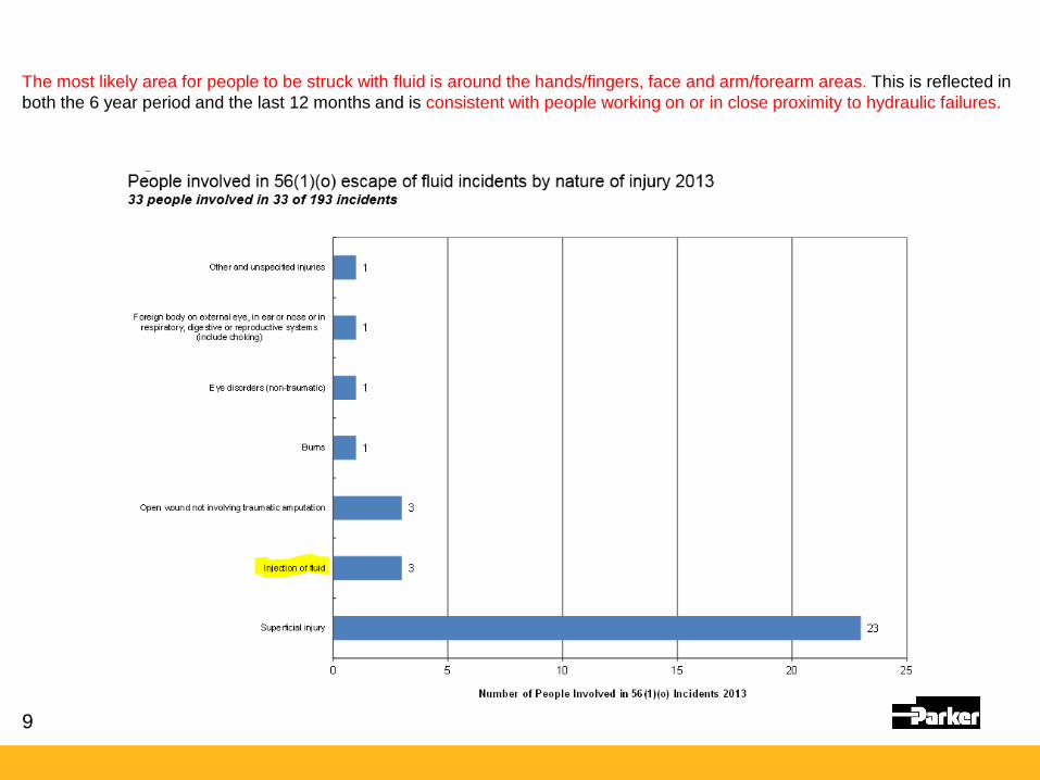
The most likely area for people to be struck with fluid is around the hands/fingers, face and arm/forearm areas. This is reflected in both the 6 year period and the last 12 months and is consistent with people working on or in close proximity to hydraulic failures.

10
Operation Type 2007 2008 2009 2010 2011 2012 2013 TotalUnderground 1 1 1 1 0 0 3 7Surface 0 1 0 0 0 1 0 2
Total 1 2 1 1 0 1 3 9
Circumstances of 56(1)(o) escape of fluid incidents with 55(a)(v) fluid injection injuries
a) Outbye: A brain pump blockage in the delivery line and air pressurised, releasing fluid pressure which struck a person in the
leg. (deputy, permanent employee, pumping duties). b) Coal handling plant: A painter was cleaning an airless spray gun which injected fluid into his finger. (painter [operator]
contractor employee, surface painting duties, injected in finger). c) Development unit: Employees were cable bolting and the cable bolt tensioner pipe ruptured due to intensification.
(contractor employee supervisor, secondary bolting operations, struck in the hand – fingers) d) Longwall: A staple was removed from a pressurised inter chock hose which released fluid injecting the employee in his
hand. (fitter, maintenance duties, hand) e) Open cut: A contractor was cleaning equipment using pressure water cleaner and he cleaned the blocked nozzle with his
hand which injected water into his finger. (contractor, cleaning operations, injected in finger). f) Open cut: Fitter received a high pressure grease injury to left upper chest when pressure was retained in grease system
when removing a component on excavator. (fitter, permanent employee, chest) g) Development unit: A contract operator received an injection of hydraulic oil to his right forearm from a blown hose while
operating R/H inner bolting rig on a continuous miner. He went to remove the dolly from the drill motor and as he reached to remove the dolly a hydraulic hose burst hitting him. (miner, contractor, arm/forearm)
h) Outbye: A contract fitter while attempting to identify a blown hose was moving hoses out of the way with his left hand and operating a hydraulic lever with his right hand when he received an oil injection to his left hand ring finger. (Fitter, contractor, hands and fingers). This injury also resulted in loss of consciousness.
i) Outbye: A Mineworker was cleaning mud around a QDS tongue retract hose on an LHD in order to identify a suspected oil leak. He asked the LHD operator to activate the function while he had his hand near the damaged hose resulting in an oil injection which required surgery. (miner, permanent employee, hands and fingers)

11
MINING DESIGN GUIDELINE | MDG 41
Work health and Safety Legislation 2.1.2 General duties in relation plant A person conducting a business or undertaking (PCBU) has a primary duty of care under section 19 of the WHS Act to ensure, so far as is reasonably practicable, that workers and other people are not exposed to health and safety risks arising from the business or undertaking. This duty includes ensuring, so far as is reasonably practicable:
•the provision and maintenance of safe plant and structures
•the provision and maintenance of safe systems of work
•the safe use, handling and storage of plant and structures
•the provision of any information, training, instruction and supervision that is necessary to protect all persons from risks to their health and safety arising from work carried out as part of the conduct of the business or undertaking.
In meeting this duty at a mine, a PCBU must manage risks to health and safety associated with mining operations at the mine in accordance with part 3.1 of the WHS Regulation and clause 9 of the WHS (Mines) Regulation 2014:
•ensuring that a risk assessment is conducted by a person who is competent to conduct the particular risk assessment having regard to the nature of the hazard
•identifying all reasonably foreseeable hazards
•eliminate risks to health and safety so far as is reasonably practicable
•if it is not reasonably practicable to eliminate risks to health and safety – minimise risks so far as reasonably practicable in accordance with the hierarchy of risk control measures
12
MINING DESIGN GUIDELINE | MDG 41
2.4 Plant safety file Safety-related aspects of fluid power systems should be fully documented. These records should be maintained in a plant safety file that covers the lifecycle of the system. The plant safety file should be created by the designer and maintained by the person in control of the fluid power system. The plant safety file should contain the following information:
a) design specifications, performance and operational conditions
b) design documentation
c) installation requirements
d) hazard identification and risk assessment documents
e) risk control methods
f) identification of all safety-critical systems and their safety category or integrity level
g) consultation records
h) commissioning and test results
i) maintenance records, safety inspections and test reports
j) change of procedures, monitoring, audit and review reports
k) reports of accidents and safety statistics
l) fluid system alterations.
The records should be stored and maintained in such a way that they are readily retrievable and protected against damage, deterioration or loss. A plant safety file may not necessarily be one complete document, and may refer to where the information can be obtained.

13
MINING DESIGN GUIDELINE | MDG 41
3.3 Fluid power systems design 3.3.1 General Fluid power systems should be designed and components selected to provide safe operation over the intended design lifecycle of the systems.
Seals and sealing devices should be compatible with the fluid used, adjacent materials, working conditions and environment.
Fluid systems should be designed to minimise excessive heat generation.
3.3.2 Rated working pressure To avoid pressurised fluids escaping into the environment, fluid power system components should have appropriate factors of safety on the rated working pressure to bursting pressure.
Hose assemblies should have a factor of safety of at least 4:1.
Adaptor fittings should have a factor of safety of at least:
a) 4:1 on rated working pressure to catastrophic failure of the adaptor or fitting b) 2.5:1 on the rated working pressure to yield or deformation of the component. Other fluid power components, such as cylinders, valves, actuators or similar should have a factor of safety of at least 2.5:1.
Where the above safety factors are reduced, appropriate engineering analysis and/or cycle and endurance testing should be carried out and documented. ISO 7751 provides guidance.
Energy conversion components such as pumps, motors, cylinders, gas charged accumulators, reservoirs, etc should be designed in accordance with ISO 4413 & ISO 4414

14

15
MINING DESIGN GUIDELINE | MDG 41
3.7.6.2 Staple type fittings Staple lock connections are a legacy longwall technology, which need be managed with appropriate control measures to be implemented for continued use. Staples are not recommended above those pressures nominated in DIN 20043, BS 6537 and SAE J1467. All staple life expectancy is limited by cyclic loading (cyclic fatigue). This information should be included in suppliers data.
People have suffered fatal injuries from the withdrawal of a staple type fittings when the fitting inadvertently or unknowingly remained under pressure. For this reason, consideration should be given to alternative to staple type fittings when designing new fluid power systems. Staple fittings should only be used when there is no other reasonably practicable alternative fitting.
Unlike some other fittings, a staple fitting does not leak and gives no indication there is pressurised fluid in the system when the staple is being removed. Once the staple is removed full pressure and flow will expel from the fitting.
There are alternate non staple/pin connections available cannot be disconnected under pressure that may be suitable.

16
MINING DESIGN GUIDELINE | MDG 41
3.3.4 Protection from uncontrolled escape of pressurised fluids The design should minimise the risk of injury to operators and maintenance personnel from the uncontrolled escape of pressurised fluids. Controls must be provided in accordance with the hierarchy of controls, refer 2.1.2. Consideration should be given to: a) routing hoses, pipes and pressurised components away from high risk areas, or otherwise as far away as is possible b) use of protective fixed guards to prevent escaped fluids entering work areas c) use of devices to divert or disperse the escaped fluid d) providing means to detect a potential component failure before it occurs e) providing means for effective isolation, energy dissipation and verification, refer Clause 3.6. It is not considered acceptable to solely rely on PPE in high-risk areas. 3.7.2.8 Hose assembly energy diffusion devices
Where hoses are in a high-risk area and there is no other means to provide protection from the uncontrolled escape of pressurised fluids, a hose assembly energy diffusion device may be appropriate if an unacceptable residual risk remains for potential harm to people. Diffusion devices may limit inspection for damage and hose deterioration. When used – the hose assembly energy diffusion device should be able to diffuse the energy in the hydraulic fluid, to a level where fluid injection will not occur provision should be made for the safe routine inspection of the hose contained within the diffusion device. Inspection of hose assemblies should be undertaken with the sleeves removed Diffusion sleeves are required to be a loose fit over the hose to redirect the energy of any ejected fluid. Covering layers of spiral guarding may negate the effectiveness of the sleeve the sleeve should be manufactured from high abrasion, ozone, heat resistant material and should be suitably attached in underground coal mines this sleeve should be fire resistant.

17
MINING DESIGN GUIDELINE | MDG 41
3.7.2.10 Fire resistance All hydraulic hose assemblies should be fire resistant unless the hose is in a low risk fire area. Fire resistance hoses should be tested in accordance with AS 1180-10B or ISO 8030 and the average duration of the flaming and glowing should not exceed 30 seconds. MDG 3608 provides guidance on FRAS in underground coal mines.
6.2 Hydraulic Hose • Hydraulic hose is used in underground coal mines shall be constructed of materials that meet the following
requirements. 6.2.1.1 Fire Resistance • When tested in accordance with ISO 8030, meets the requirements of ISO 6805:1994 Clause 15. 6.2.1.2 Electrical Resistance • When tested in accordance with ISO 8031,meets the requirements of ISO 6805:1994 Clause 14.

18
MINING DESIGN GUIDELINE | MDG 41
3.7.3.3 Effective service life In order to maximise the effective service life of hose assembly, design and installation should be carried out in accordance with SAE J1273 or ISO 17165-2. Poor design of installation standards is a predominate factor in effective service life In addition consideration should be given to: a) external cover protection that may be exposed to abrasion or impact damage b) shielding to protect hose assemblies from heat sources such as engine manifolds, exhausts, turbos etc c) accidental damage caused by: falling rock, vehicle collision, tensile load, shear load, crushing, fire d) mechanical loads – vibration, tensile, shear e) corrosive spillage, molten metal, pressure surge f) corrosion of end fittings (alkalinity / acidic water) / Coal (sulphur) g) heat generated internally and externally to the hose assembly h) refer hose life degradation (ref S-N studies) ACARP C17020 i) working fluid temperature, velocity and contamination.

19
MINING DESIGN GUIDELINE | MDG 41
3.7.3.4 Hose and hose assembly shelf life and storage Storage and age control can affect hose life. The following should be considered: a) A system of age control should be implemented to ensure hose assemblies are used prior to shelf life expiration. b) Hose and hose assemblies should be stored in accordance with ISO 8331. c) Storage areas should be relatively cool and dark, as well as free of dust, dirt, dampness and mildew. d) Hose and hose assemblies can be adversely affected by temperature, humidity, ozone, sunlight, ultraviolet light, oils,
solvents, corrosive liquids, and fumes, acids and alkalis, insects, rodents, sharp edges and abrasive surfaces, electric or strong magnetic fields, mould and fungi, and radioactive materials.
e) Storage of tested hose assemblies should be limited to two years from inspection, refer to SAE J1273 Clause 9.1.c. f) Hose assembly stored for more than two years, should be visually inspected and proof tested or follow manufacturer’s
recommendations. g) Hose assemblies with hose older than five years (five years or greater post cure date) should be re-proof tested (see
3.8.7.1) and hose assemblies with hose older than eight years should be discarded unless otherwise recommended by the hose manufacturer. After successfully retesting, the hose assemblies should be clearly remarked.

20
MINING DESIGN GUIDELINE | MDG 41
3.7.6.1 General Hose ends should not be interchanged and should be properly matched to the hose based on proven type test result. Only select hose ends compatible with the hose for the application. The fitting and hose manufacturer’s recommendations should be strictly followed.

21
MINING DESIGN GUIDELINE | MDG 41
3.9.7 Operation and maintenance instructions Operation and maintenance manuals should be provided. These manuals should contain the following information categorised in appropriate sections: a) Recommended maintenance requirements to maintain the fluid system in a safe operating condition. b) Recommended inspection and tests, to check if the equipment is safe to operate. c) Identification of any hazards involved in maintaining and operating the equipment. d) Identification of all high risk areas. e) Energy isolation, dissipation and control procedures. f) Safe work procedures to carry out maintenance on the system, including setting of controls. g) Protective equipment requirements. h) Trouble shooting guide. i) Safe handling and disposal of fluids. j) Recommended spares.

22
MINING DESIGN GUIDELINE | MDG 41
4.1 Manufacture and assembly - of fluid power systems and components Manufacturers and assemblers of fluid power systems and components should use the design specifications provided by the designer. Clause 193 of the WHS Regulation imposes specific duties on the manufacturer of plant. The following should be considered in the manufacture and assembly of fluid power systems and components: • Specific conditions relating to the method of manufacture. • Instructions for fitting or refitting plant parts and their location on other components of the plant or their housings
where errors could be made when installing the plant. • Instruction where hot or cold parts or material may create a hazard. • Specifications of material. • Schematic diagrams. • Specifications for proprietary items e.g. electric motors. • Component specifications including drawings and tolerances. • Assembly drawings. • Assembly procedures including specific tools or equipment to be used. • Manufacturing processes e.g, requirements for crimping. • Details of hazards presented by materials during manufacturing. • Safety outcomes Any alterations during the manufacturing / assembly phase of a fluid power systems is considered a design change in which designers obligations apply.

23
MINING DESIGN GUIDELINE | MDG 41
7.1.1 Competence All people associated with the maintenance of the fluid power system (including contractors) should be competent to safely carry out work on the fluid system.
Some relevant competencies include:
•MEM18052B Maintain fluid power systems for mobile plant •Minimum Bend Radius •Minimum Bend Radius AURTTA3013 Repair hydraulic systems
Competence of maintenance personnel should include:
a)system functional requirements and operating parameters b)troubleshooting and individual component testing c)safe energy isolation and dissipation in accordance with the mines isolation management plan d)electrical / fluid power interfaces and control circuitry e)hose management f)importance of cleanliness g)energy isolation process in particular hazardous activity isolation. Specific competence on energy isolation should be carried out on large and complex fluid power systems such as longwall roof supports.
24
MINING DESIGN GUIDELINE | MDG 41
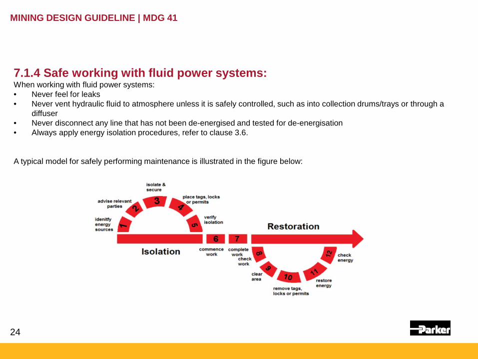
7.1.4 Safe working with fluid power systems: When working with fluid power systems: • Never feel for leaks • Never vent hydraulic fluid to atmosphere unless it is safely controlled, such as into collection drums/trays or through a
diffuser • Never disconnect any line that has not been de-energised and tested for de-energisation • Always apply energy isolation procedures, refer to clause 3.6. A typical model for safely performing maintenance is illustrated in the figure below:

25
MINING DESIGN GUIDELINE | MDG 41
7.2 Isolation and energy dissipation The mine will have an energy isolation management plan, refer to MDG 40
This plan will include:
a)an energy isolation process used for the de-energisation of all energies b)an assessment process for people who need to demonstrate competence c)identified specific isolation processes for high risk activities d)emergency management e)training. All safe work methods should identify energy isolation, dissipation and verification requirements.
MDG 40 offers guidance on the requirements for energy isolation management.
26
MINING DESIGN GUIDELINE | MDG 41
3.6.1 General
In the performance of many lifecycle tasks such as installation, repair, service, component replacement, maintenance and disassembly it is imperative to have isolation and energy dissipation considered in the design of the fluid power system.
Isolation valves should not be installed in the return circuit of a hydraulic system as they provide a means for pressure intensification if left closed.
The design risk assessment should consider effective means of energy isolation, dissipation and verification of fluid power hazards. This should include:
a) identification of all energy sources to prevent a release of energy, (such as stored fluid power, gravity, (suspended loads), springs, electrical) and / or prevent unintended activation or movement of equipment
b) provision of a means to isolate all identified energy sources to prevent a possible state change. This includes purpose designed isolation devices that are lockable.
c) provision of a means to safely dissipate fluid. If used as part of the isolation process a dissipation device should be a purpose-designed dissipation devices and lockable.
d) provision of a system that verifies that pressure has been dissipated. (Test for dead or safe state) e) clear identification of all isolation and dissipation points f) provision of safe work methods for the use of the isolation, dissipation and verification devices. Should include removal
and restoration of energy. g) information on required people competence to isolate, diffuse and verify isolation.

27
MINING DESIGN GUIDELINE | MDG 41
7.6 Hose assembly management 7.6.1 General A hose management plan should be developed, implemented and maintained (refer to clause 7.5 and clause 3.7.12). The hose management plan should be established and maintained in consultation with all stakeholders, including site management, maintenance and suppliers. The hose management plan should be integral with the mines maintenance system and the site specific maintenance strategies. A hose management program will reduce equipment downtime, maintain peak operating performance, and reduce the risk for personal injury and/or property damage. The hose management plan should include: • A database of the range of hose assemblies on the mine site • A maintenance schedule such that all hose assemblies are inspected at a frequency as required for their risk to safety and
equipment operation, refer Work Health and Safety (Mines) Regulation 2014 Section 13 and Schedule 2. • Discarded hose assemblies or hoses with no known history (e.g. longwall, monorail, AFC/BSL hoses) not being reinstalled
unless tested and certified in accordance with clause 3.7.11.1 Individual Hose assembly proof testing. If reinstalled, the hoses being cleaned and labelled in readiness for reuse. This is not intended to include the disconnection and reconnection for operational or maintenance purposes.
• Hose failure mode analysis.

28
MINING DESIGN GUIDELINE | MDG 41
MDG41 is not a Hose & fitting standard MDG41 is not a Compliance document
29
MINING DESIGN GUIDELINE | MDG 41 Guideline for fluid power system safety at mines
Focuses on risk management & mitigation controls to be considered, along with competency and operational guidance. MDG41 now also incorporates links to other relevant data and historical incident reporting along with exposure frequency for more meaningful Risk Assessments.

30
Thank you