mcu: interrupts and timers ganesh pitchiah. what’s an mcu ?
TRANSCRIPT
MCU: Interrupts and Timers
Ganesh Pitchiah

What’s an MCU ?
Frequency = 8 MHzTime Period = 1/f = 0.125 us
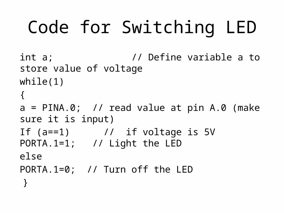
Code for Switching LED
int a; // Define variable a to store value of voltage while(1){a = PINA.0; // read value at pin A.0 (make sure it is input)If (a==1) // if voltage is 5V
PORTA.1=1; // Light the LEDelse
PORTA.1=0; // Turn off the LED }
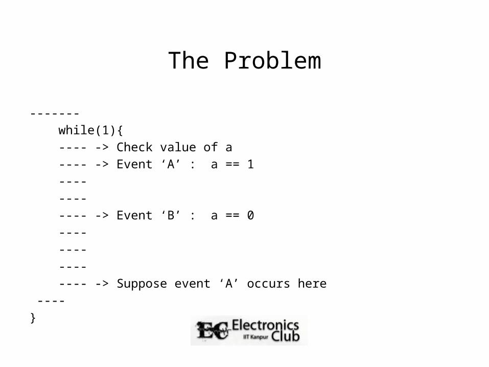
The Problem
------- while(1){ ---- -> Check value of a ---- -> Event ‘A’ : a == 1 ---- ---- ---- -> Event ‘B’ : a == 0 ---- ---- ---- ---- -> Suppose event ‘A’ occurs here ---- }
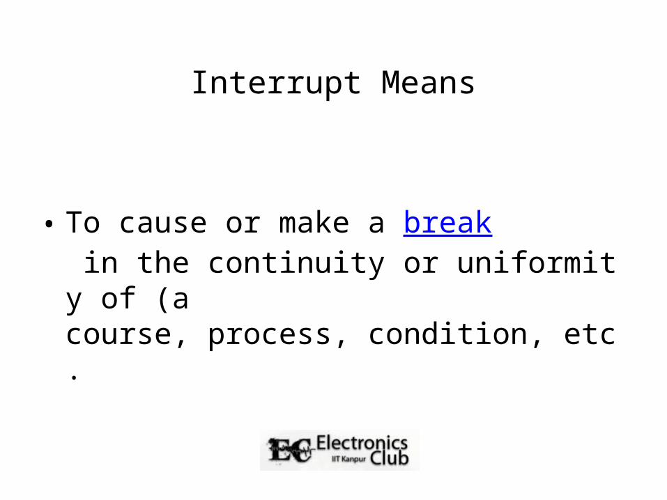
Interrupt Means
• To cause or make a break in the continuity or uniformity of (a course, process, condition, etc.
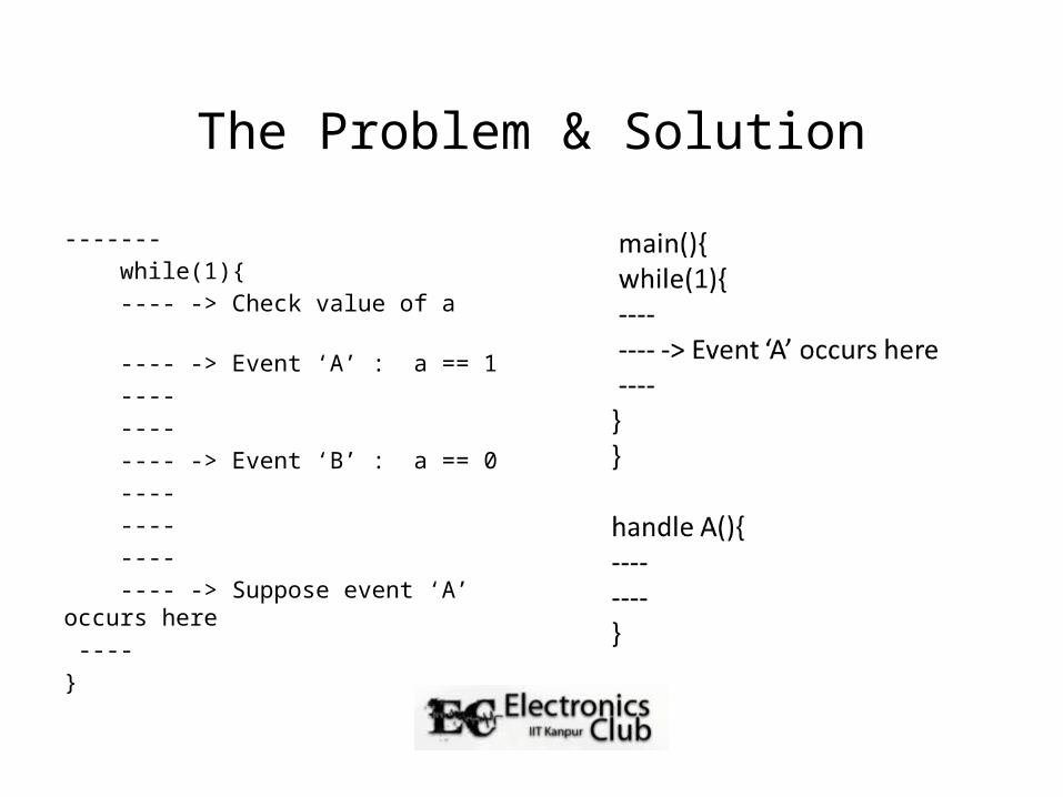
The Problem & Solution
------- while(1){ ---- -> Check value of a ---- -> Event ‘A’ : a == 1 ---- ---- ---- -> Event ‘B’ : a == 0 ---- ---- ---- ---- -> Suppose event ‘A’ occurs here ---- }
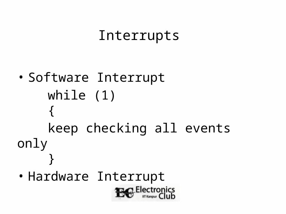
Interrupts
• Software Interrupt while (1) { keep checking all events only }• Hardware Interrupt

Why Interrupts?
• Interrupts are special events that can “interrupt” the normal flow of a program.
• The processor stops the normal program, handles the interrupt, and then resumes its normal work.
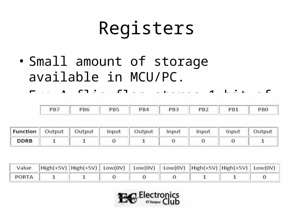
Registers
• Small amount of storage available in MCU/PC.• Ex: A flip flop stores 1-bit of memory.
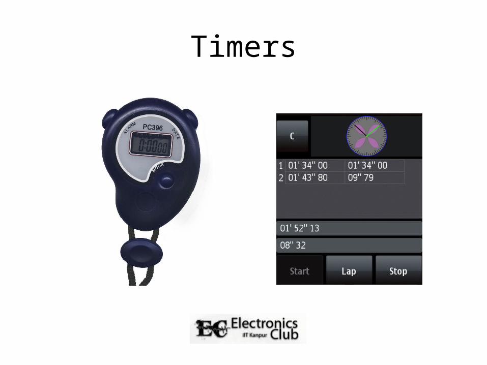
Timers
Timers
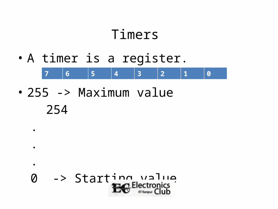
• A timer is a register. • 255 -> Maximum value 254
.
.
. 0 -> Starting value
7 6 5 4 3 2 1 0
Timers
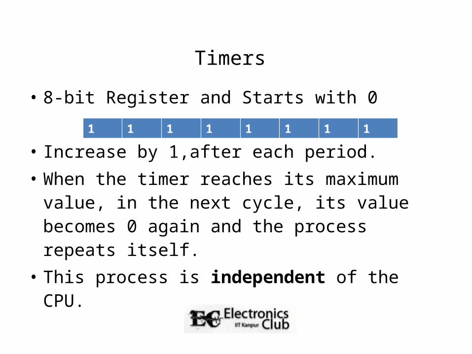
• 8-bit Register and Starts with 0 • Increase by 1,after each period. • When the timer reaches its maximum value, in
the next cycle, its value becomes 0 again and the process repeats itself.
• This process is independent of the CPU.
7 6 5 4 3 2 1 00 0 0 0 0 0 0 00 0 0 0 0 0 0 10 0 0 0 0 0 1 01 1 1 1 1 1 1 1
Simple statistics
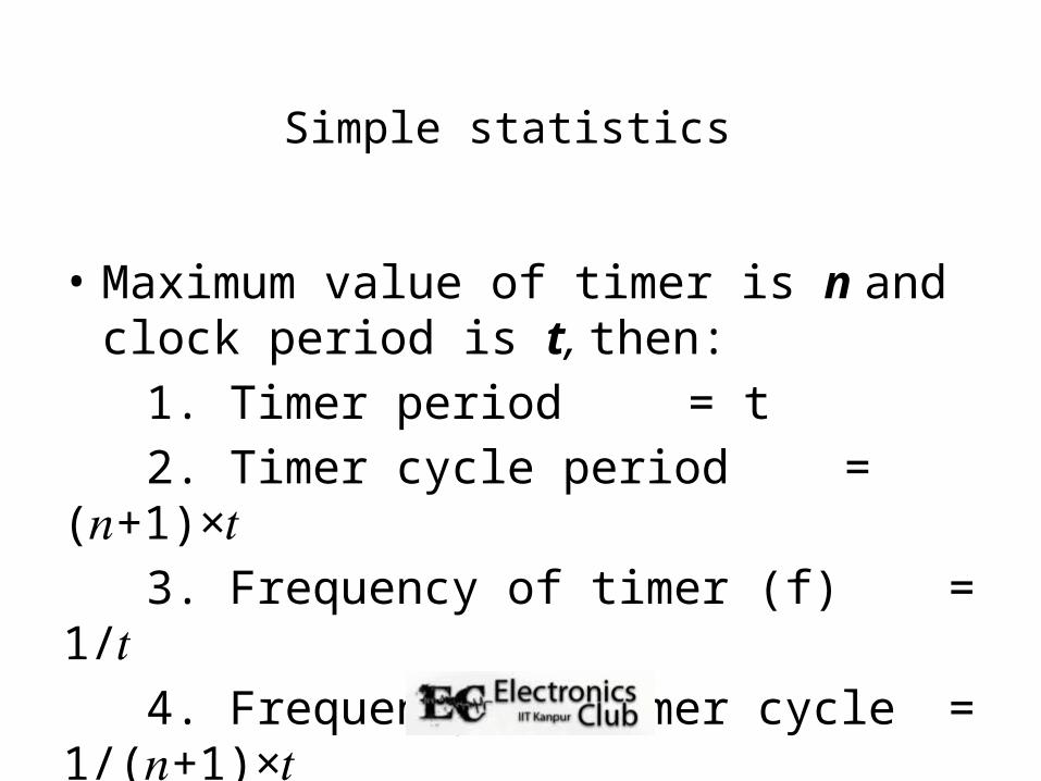
• Maximum value of timer is n andclock period is t, then:
1. Timer period = t 2. Timer cycle period = ( +1)× 𝑛 𝑡 3. Frequency of timer (f) = 1/ 𝑡 4. Frequency of timer cycle = 1/( +1)× 𝑛 𝑡
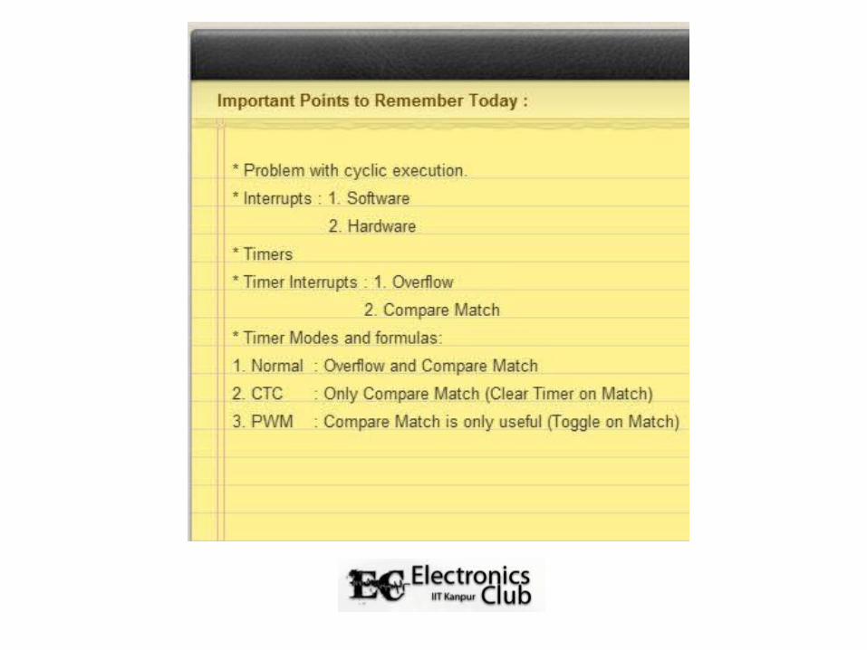
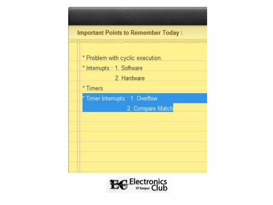
Timers and Interrupts
• Timers can generate certain two interrupts: 1. OVERFLOW interrupt and 2. COMPARE MATCH interrupt.
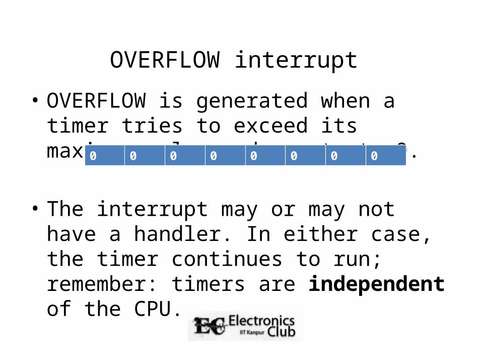
OVERFLOW interrupt
• OVERFLOW is generated when a timer tries to exceed its maximum value and resets to 0.
• The interrupt may or may not have a handler. In either case, the timer continues to run; remember: timers are independent of the CPU.
0 0 0 0 0 0 0 0
OVERFLOW statistics
• Suppose a timer of maximum value n has a time period t (also called as clock period).
1. Timer cycle frequency = 1/( +1)× 𝑛 𝑡 2. OVERFLOW interrupt frequency = 1/( +1)×𝑛 𝑡• If OVERFLOW interrupt is enabled, then an
interrupt is generated in every cycle.
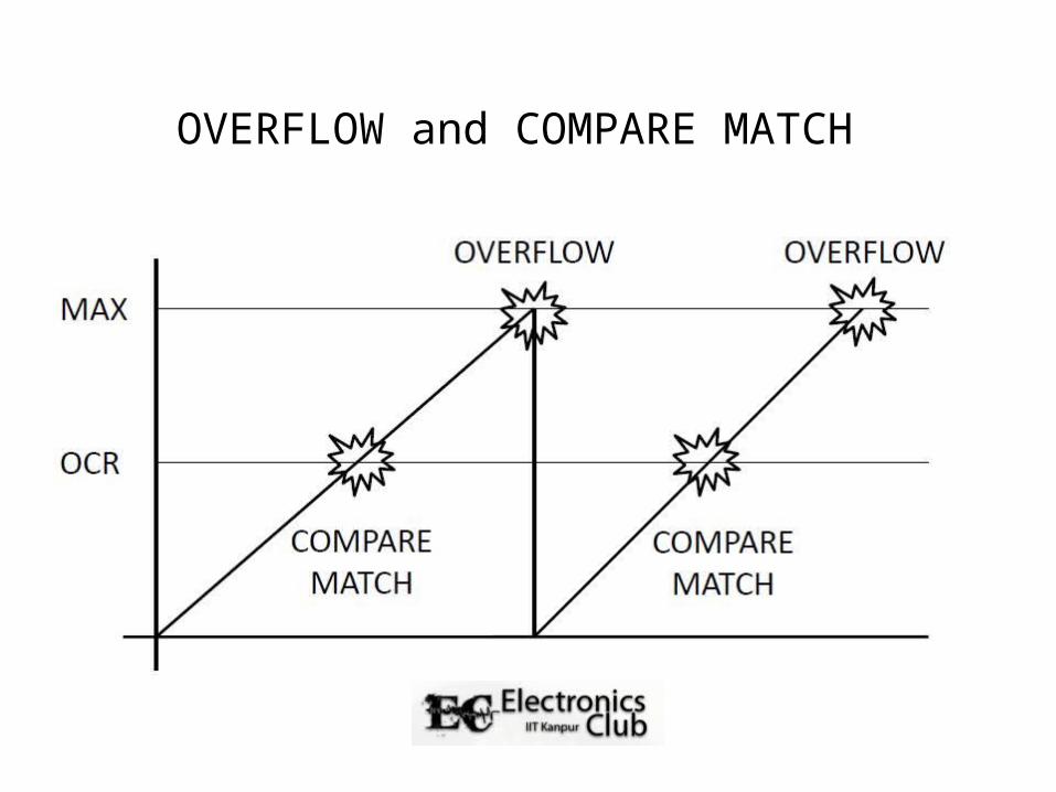
OVERFLOW and COMPARE MATCH
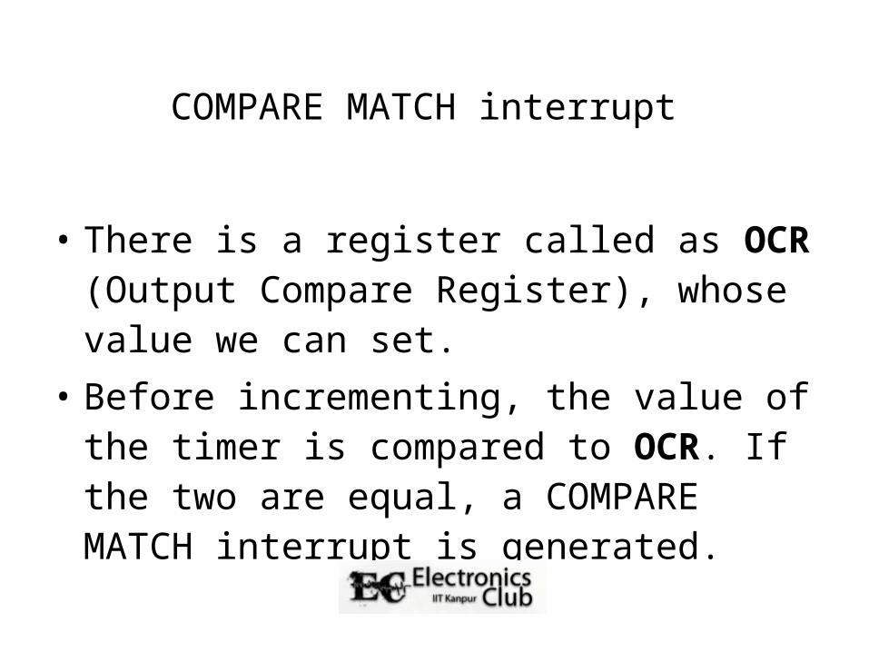
COMPARE MATCH interrupt
• There is a register called as OCR (Output Compare Register), whose value we can set.
• Before incrementing, the value of the timer is compared to OCR. If the two are equal, a COMPARE MATCH interrupt is generated.
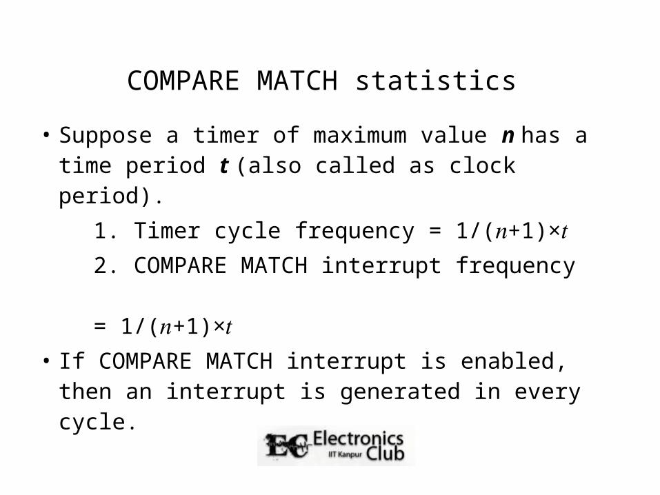
COMPARE MATCH statistics
• Suppose a timer of maximum value n has a time period t (also called as clock period).
1. Timer cycle frequency = 1/( +1)× 𝑛 𝑡 2. COMPARE MATCH interrupt frequency = 1/( +1)× 𝑛 𝑡• If COMPARE MATCH interrupt is enabled, then
an interrupt is generated in every cycle.

OVERFLOW and COMPARE MATCH
Summary of Timers
• A timer is not affected by interrupts: it generated interrupts, but it does not stop running because of them.
• Interrupts is how timers are useful. Sample applications: digital clock, periodic events (such as blinking LEDs quickly for POV globe), etc.
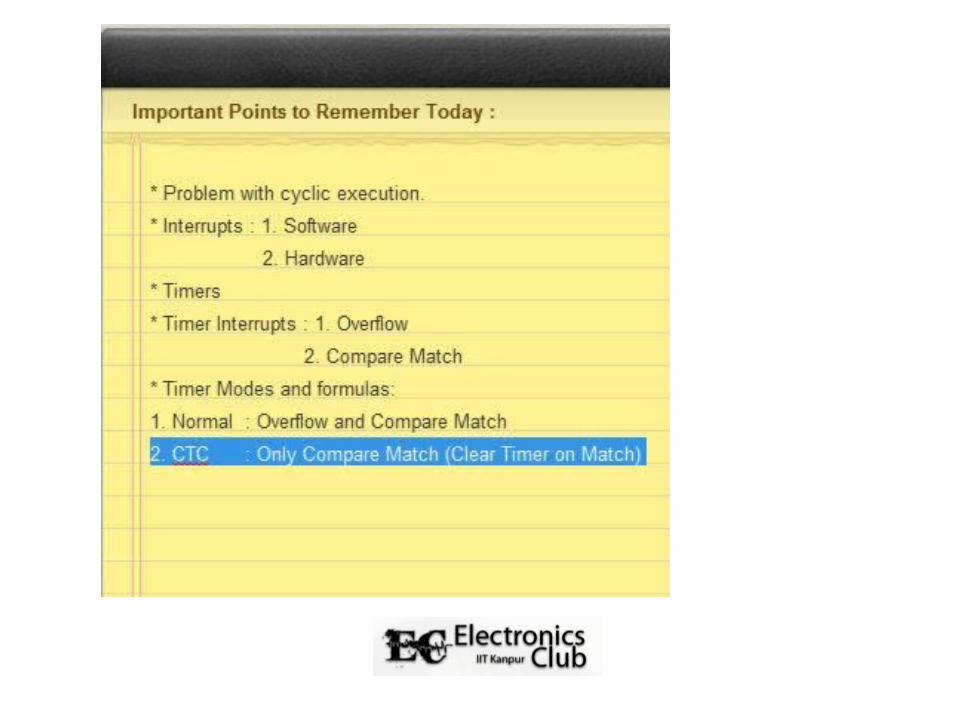
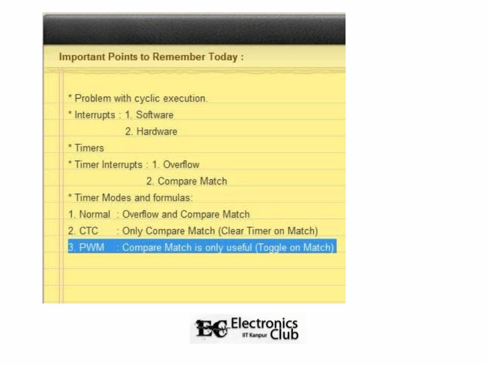
Timer Modes
• A timer works in three modes: Normal, CTC and PWM.
• All three modes are again unaffected by interrupts, but all three modes can generate interrupts.
• The timer mode used so far in this presentation is normal mode.
Normal Mode
• Standard mode: Timer starts at 0, goes to maximum value and then resets itself.
• OVERFLOW and COMPARE MATCH interrupts generated as normal.
CTC (Clear Timer on Compare) Mode
• Timer starts at 0 as usual, but instead of resetting after maximum value, it resets after reaching value specified in OCR register.
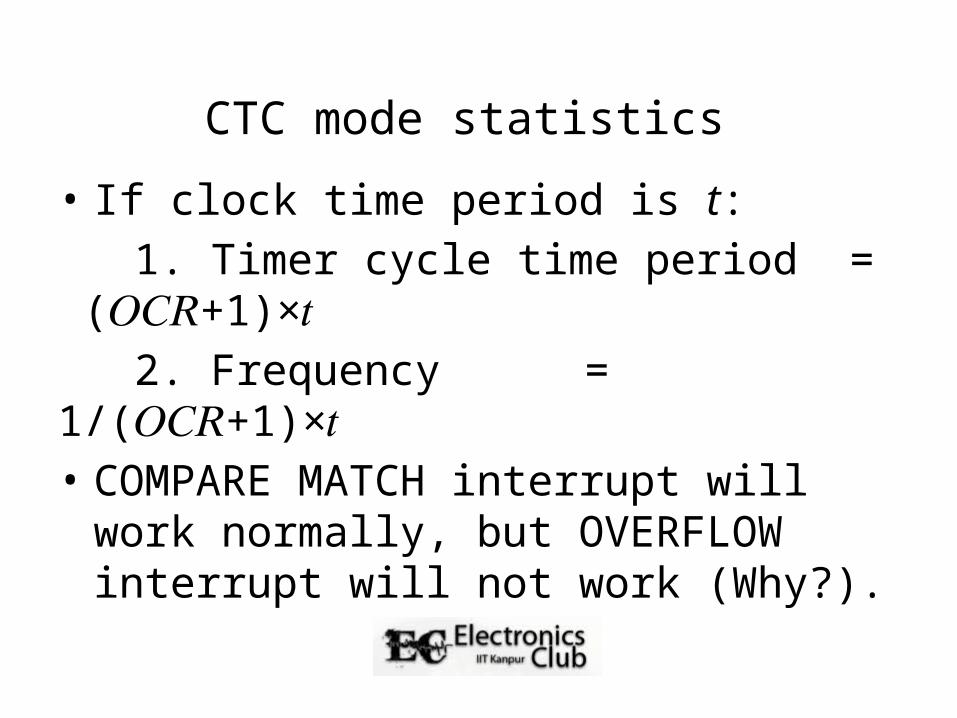
CTC mode statistics
• If clock time period is t: 1. Timer cycle time period = ( +1)× 𝑂𝐶𝑅 𝑡 2. Frequency = 1/( +1)× 𝑂𝐶𝑅 𝑡• COMPARE MATCH interrupt will work
normally, but OVERFLOW interrupt will not work (Why?).
PWM (Pulse Width Modulation) Mode
• Simple method of obtaining analog output of any value between 0 and 5V.
• Desired output is x% of 5V. • If Ton = x% then average value is x% of 5V.
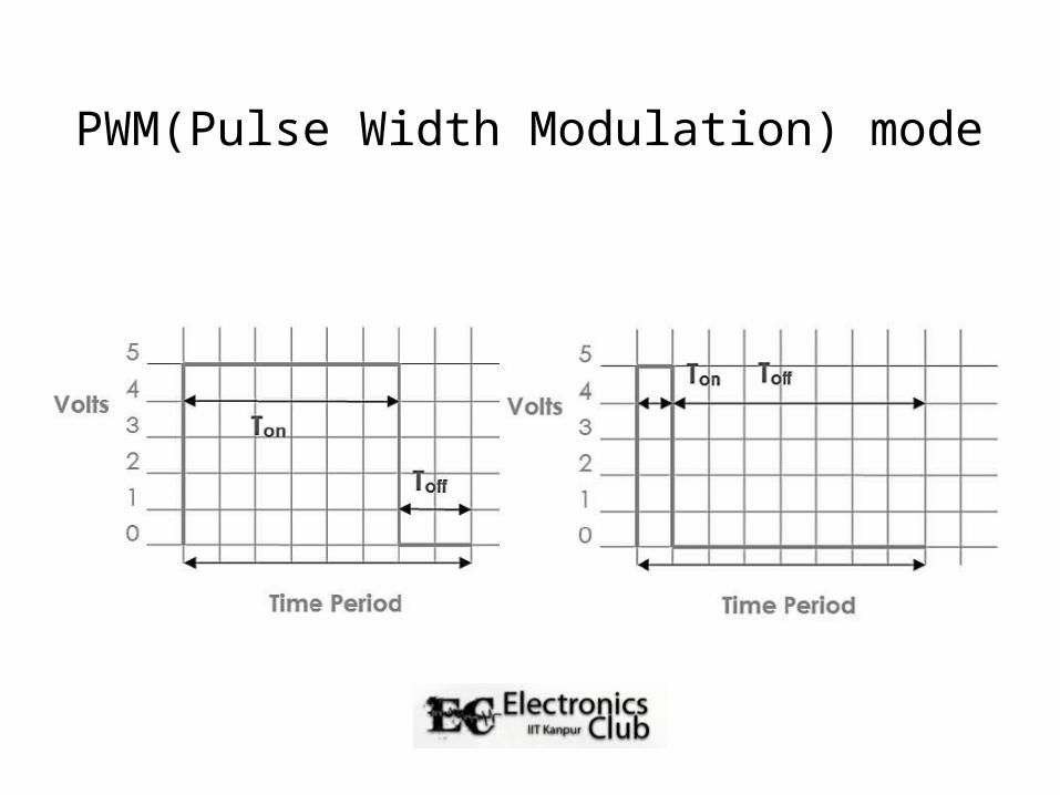
PWM(Pulse Width Modulation) mode
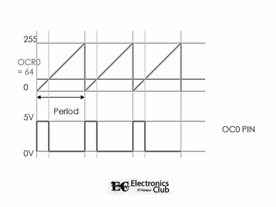
• A specific pin is set as output. • When the timer reaches 0, the voltage of the
pin is set to 5V. • When the timer reaches the value specified by
OCR, on the next clock, the pin voltage is set to 0 until the timer resets itself.
PWM mode
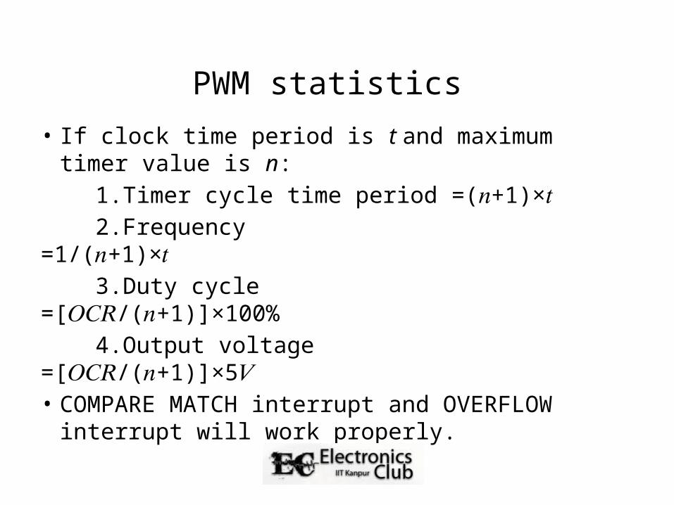
PWM statistics
• If clock time period is t and maximum timer value is n:
1.Timer cycle time period =( +1)× 𝑛 𝑡 2.Frequency =1/( +1)× 𝑛 𝑡 3.Duty cycle =[ /( +1)]×100% 𝑂𝐶𝑅 𝑛 4.Output voltage =[ /( +1)]×5 𝑂𝐶𝑅 𝑛 𝑉• COMPARE MATCH interrupt and OVERFLOW
interrupt will work properly.
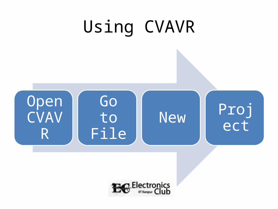
Using CVAVR
Open CVAVR
Go to File New Project
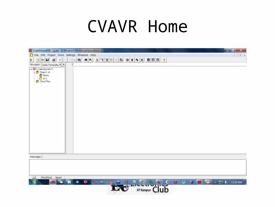
CVAVR Home
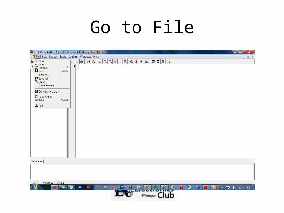
Go to File
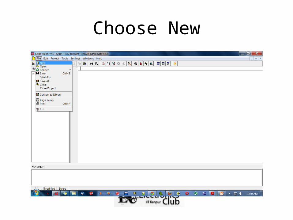
Choose New
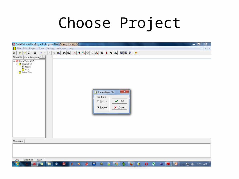
Choose Project
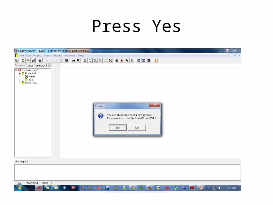
Press Yes
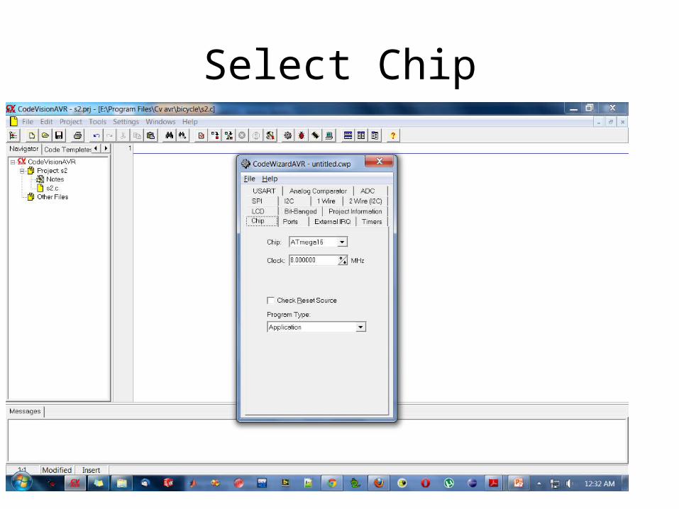
Select Chip
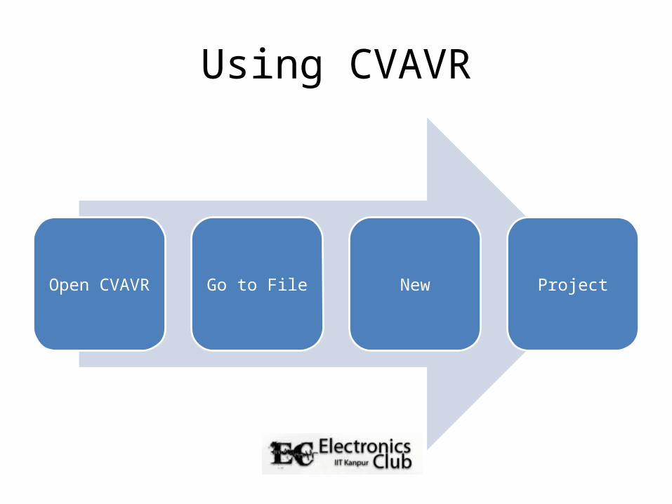
Using CVAVR
Open CVAVR Go to File New Project
Demo