mcpat: an integrated power, area, and timing modeling
TRANSCRIPT

McPAT: An Integrated Power, Area, and Timing ModelingFramework for Multicore and Manycore Architectures
Sheng Li†‡, Jung Ho Ahn§‡, Richard D. Strong¶, Jay B. Brockman†, Dean M. Tullsen¶, Norman P. Jouppi‡†University of Notre Dame, ‡Hewlett-Packard Labs,
§Seoul National University, ¶University of California, San Diego†{sli2, jbb}@nd.edu, ‡[email protected], §[email protected], ¶{rstrong, tullsen}@cs.ucsd.edu
ABSTRACTThis paper introduces McPAT, an integrated power, area,and timing modeling framework that supports comprehen-sive design space exploration for multicore and manycoreprocessor configurations ranging from 90nm to 22nm andbeyond. At the microarchitectural level, McPAT includesmodels for the fundamental components of a chip multipro-cessor, including in-order and out-of-order processor cores,networks-on-chip, shared caches, integrated memory con-trollers, and multiple-domain clocking. At the circuit andtechnology levels, McPAT supports critical-path timing mod-eling, area modeling, and dynamic, short-circuit, and leak-age power modeling for each of the device types forecast inthe ITRS roadmap including bulk CMOS, SOI, and double-gate transistors. McPAT has a flexible XML interface tofacilitate its use with many performance simulators.
Combined with a performance simulator, McPAT enablesarchitects to consistently quantify the cost of new ideas andassess tradeoffs of different architectures using new metricslike energy-delay-area2 product (EDA2P) and energy-delay-area product (EDAP). This paper explores the interconnectoptions of future manycore processors by varying the degreeof clustering over generations of process technologies. Clus-tering will bring interesting tradeoffs between area and per-formance because the interconnects needed to group coresinto clusters incur area overhead, but many applicationscan make good use of them due to synergies of cache shar-ing. Combining power, area, and timing results of McPATwith performance simulation of PARSEC benchmarks at the22nm technology node for both common in-order and out-of-order manycore designs shows that when die cost is nottaken into account clustering 8 cores together gives the bestenergy-delay product, whereas when cost is taken into ac-count configuring clusters with 4 cores gives the best EDA2Pand EDAP.
Categories and Subject DescriptorsC.0 [Computer Systems Organizations]: GENERAL
Permission to make digital or hard copies of all or part of this work forpersonal or classroom use is granted without fee provided that copies arenot made or distributed for profit or commercial advantage and that copiesbear this notice and the full citation on the first page. To copy otherwise, orrepublish, to post on servers or to redistribute to lists, requires prior specificpermission and/or a fee.MICRO’09, December 12–16, 2009, New York, NY, USA.(c) 2009 ACM 978-1-60558-798-1/09/12 ...$10.00.
General TermsPerformance, Verification
1. INTRODUCTIONIt has always been true in this community that tools both
limit and drive research directions. Wattch [8], first pre-sented in 2000, has been such a tool, enabling a tremendoussurge in power-related architecture research. However, sev-eral factors drive the need for new tools to address changesin architecture and technology. This includes the need toaccurately model multicore and manycore architectures, theneed to model and evaluate power, area, and timing simul-taneously, the need to accurately model all sources of powerdissipation, and the need to accurately scale circuit mod-els into deep-submicron technologies. This paper introducesa new power, area, and timing modeling framework calledMcPAT (Multicore Power, Area, and Timing), which ad-dresses these challenges.
McPAT advances the state of the art in several direc-tions compared to Wattch, which is the current standard forpower research. First, McPAT is an integrated power, area,and timing modeling framework that enables architects touse new metrics combining performance with both powerand area such as energy-delay-area2 product (EDA2P) andenergy-delay-area product (EDAP), which are useful to quan-tify the cost of new architectural ideas. McPAT specifies thelow-level design parameters of regular components (e.g. in-terconnects, caches, and other array-based structures) basedon high-level constraints (clock rate and optimization tar-get) given by a user, ensuring the user is always modeling areasonable design. This approach enables the user, if theychoose, to ignore many of the low-level details of the circuitsbeing modeled.
Second, McPAT models more than just dynamic power,which is critical in deep-submicron technologies since staticpower has become comparable to dynamic power [38]. Mc-PAT models all three types of power dissipation—dynamic,static, and short-circuit power—to give a complete view ofthe power envelope of multicore processors.
Third, McPAT provides a complete, integrated solutionfor multithreaded and multicore/manycore processor power.Some researchers have combined Wattch’s core power modelwith a router power model [18], but even that is an incom-plete solution. Today’s multicores are complex systems ofcores, caches, interconnects, memory controllers, multiple-domain clocking, and other components. McPAT models thepower of most of the important parts of multicore processors,

including all of the components listed above. Modeling mul-tithreaded processors using Wattch is also hard since it doesnot model resource-sharing/partitioning schemes nor hard-ware implementation overhead in multithreaded processors.Wattch models out-of-order (OOO) processors based on thesynthetic RUU model of SimpleScalar [9]. McPAT supportsmore detailed and realistic models based on existing OOOprocessors. McPAT can model both a reservation-stationmodel and a physical-register-file model based on real archi-tectures, including the Intel P6 [16] and Netburst [15].
Fourth, McPAT handles technologies that can no longerbe modeled by the linear scaling assumptions used by Wattch.The simple linear scaling principles are no longer valid be-cause device scaling has become highly non-linear in thedeep-submicron era. McPAT uses technology projectionsfrom ITRS [38] for dynamic, static, and short-circuit power;as a result, this tool will naturally evolve with ITRS evenbeyond the end of the current road map.
The remainder of this paper is organized as follows. Afterdiscussing related work in Section 2, we describe the over-all structure of McPAT in Section 3. Section 4 discussesthe hierarchical, integrated model of power, area, and tim-ing. It also presents the validation results. In Section 5, wecombine McPAT with performance simulators and explorethe interconnect options of future manycore processors byvarying the degree of clustering over generations of processtechnologies. We conclude in Section 6.
2. RELATED WORKCACTI [41] was the first tool to address the need for rapid
power, area, and timing estimates for computer architectureresearch, focusing on RAM-based structures. The most re-cent release of the tool supports SRAM and DRAM basedcaches as well as plain memory arrays. It uses device modelsbased on the industry-standard ITRS roadmap [38], usingMASTAR [38] to calculate device parameters at differenttechnology nodes. CACTI uses the method of logical effortto size transistors. It contains optimization features thatenable the tool to find a configuration with minimal powerconsumption, given constraints on area and timing.
The complexity-effective approach [33] was one of the firstattempts to use analytic models to obtain rapid estimatesfor processor timing, focusing on control, issue, selection,and bypass logic. Using generic circuit models for pipelinestages, it estimates the RC delay for each stage and deter-mines the critical path.
Wattch [8] is a widely-used processor power estimationtool. Wattch calculates dynamic power dissipation fromswitching events obtained from an architectural simulationand capacitance models of components of the microarchitec-ture. For array structures, Wattch uses capacitance modelsfrom CACTI, and for the pipeline it uses models from [33].When modeling out-of-order processors, Wattch uses thesynthetic RUU model that is tightly coupled to the Sim-pleScalar simulator [9]. Wattch has enabled the computerarchitecture research community to explore power-efficientdesign options, as technology has progressed; however, lim-itations of Wattch have become apparent. First, Wattchmodels power without considering timing and area. Sec-ond, Wattch only models dynamic power consumption; theHotLeakage package [45] partially addressed this deficiencyby adding models for subthreshold leakage. Third, Wattch
uses simple linear scaling models based on 0.8µm technol-ogy that are inaccurate to make predictions for current andfuture deep-submicron technology nodes.
Orion [18] is a tool for modeling power in networks-on-chip (NoC). Version 2.0 includes models for area, dynamicpower, and gate leakage, but does not consider short-circuitpower or timing. It uses repeated wire models for inter-connect, as well as device parameters for future technologynodes obtained from the ITRS roadmap using MASTAR andother methods. Kumar et al. provide further details on NoClayouts that take chip floorplans into consideration [22].
3. MCPAT: OVERVIEW AND OPERATIONMcPAT is the first integrated power, area, and timing
modeling framework for multithreaded and multicore/many-core processors. It is designed to work with a variety ofperformance simulators (and thermal simulators, etc.) overmany technology generations. McPAT allows the user tospecify low-level configuration details. It also provides de-fault values when the user chooses to only specify high-levelarchitectural parameters.
Figure 1 is a block diagram of the McPAT framework.Rather than being hardwired to a particular simulator, Mc-PAT uses an XML-based interface with the performancesimulator. This interface allows both the specification of thestatic microarchitecture configuration parameters and thepassing of dynamic activity statistics generated by the per-formance simulator. McPAT can also send runtime powerdissipation back to the performance simulator through theXML-based interface, so that the performance simulator canreact to power (or even temperature) data. This approachmakes McPAT very flexible and easily ported to other per-formance simulators. McPAT runs separately from a sim-ulator and only reads performance statistics from it. Per-formance simulator overhead is minor – only the possibleaddition of some performance counters. Since McPAT pro-vides complete hierarchical models from the architecture tothe technology level, the XML interface also contains circuitimplementation style and technology parameters that arespecific to a particular target processor. Examples are arraytypes, crossbar types, and the CMOS technology generationwith associated voltage and device types.
The key components of McPAT are (1) the hierarchicalpower, area, and timing models described in Section 4, (2)the optimizer for determining circuit-level implementations,and (3) the internal chip representation that drives the anal-ysis of power, area, and timing. Most of the parameters inthe internal chip representation, such as cache capacity andcore issue width, are directly set by the input parameters.
McPAT’s hierarchical structure allows it to model struc-tures at a very low level, and yet still allows an architect tofocus on the high-level configuration. The optimizer deter-mines unspecified parameters in the internal chip representa-tion, focusing on two major regular structures: interconnectsand arrays. For example, the user can specify the frequencyand bisection bandwidth of the network-on-chip, the capac-ity and the associativity of caches, or the number of cachebanks, while letting the tool determine the implementationdetails such as the choice of metal planes, the effective signalwiring pitch for the interconnect, or the length of wordlinesand bitlines of the cache bank. These optimizations lessenthe burden on the architect to figure out every detail, and

Chip
Representation
Optimizer
Timing
Area
Sta
tsC
onfigu
re MCPAT
Power/Area/
Timing Model
Arch. Circuit Tech.
Power
Dynamic
Leakage
Short-circuit
XML Interface
Op
tim
iza
tio
n
(Micro)Architecture ParamFrequency, Vdd, In-order,
OoO, Cache Size NoC type
Core count, Multithreaded? …
Circuit Parameters
SRAM, DRAM, DFF, Crossbar type ...
Tech Parameters
Device (HP, LSTP, LOP) , Wire Type
Optimization Target
Max area/power Deviation
Optimization function
Machine Stats
Hardware utilization
P-State / C-state Config
Runtime Power Stats
Thermal Stats
If thermal Model plugged in
User Input
Cycle-by-cycle
performance
simulator
Figure 1: Block diagram of the McPAT framework.
significantly lowers the learning curve to use the tool. Usersalways have the flexibility to turn off these features and setthe circuit-level implementation parameters by themselves.
The main focus of our tool is accurate power and areamodeling, and a target clock rate is used as a design con-straint. The user of McPAT specifies the target clock fre-quency, the area and power deviation, the optimization func-tion, and other architectural/circuit/technology parameters.The optimization space that McPAT explores can be huge,especially when there are many unspecified parameters. Mc-PAT does intelligent and extensive search of the design space.For each processor component, McPAT optimizes the circuit-level structure to satisfy the timing constraint. Then, if theresulting power or area is not within the allowed deviationof the best value found so far, the configuration is discarded.Finally, among the configurations satisfying the power andarea deviation, McPAT applies the optimization function toreport the final power and area values. The module power,area, and timing models together with the final chip repre-sentation generated by the optimizer are used to computethe final chip-area, timing, and peak power. The peak powerof individual units and the machine utilization statistics (ac-tivity factor) are used to calculate the final runtime powerdissipation.
Another distinguishing feature of McPAT is its ability tomodel advanced power management techniques, such as theP- and C-state [30] power management of modern proces-sors. After calling McPAT to finish initialization, a perfor-mance simulator can pass statistical information and invokeMcPAT anytime during the simulation. McPAT will thencalculate the corresponding power dissipation for the partic-ular period and send it back to the performance simulatorwhen required. This allows the simulator to react to sim-ulated power or thermal sensors (assuming a temperaturemodel is attached to the backend), by changing voltage andfrequency settings, or invoking one of multiple power-savingstates on idle circuit blocks. This allows the architect to usethe framework to model the full range of power managementalternatives.
4. MODELING FRAMEWORKS AND VAL-IDATION OF MCPAT
In order to model the power, area, and timing of a multi-core processor, McPAT takes an integrated and hierarchical
approach. It is integrated in that McPAT models power,area, and timing simultaneously. Because of this McPAT is
able to ensure that the results are mutually consistent froman electrical standpoint. It is hierarchical in that it decom-poses the models into three levels: architectural, circuit, andtechnology. This provides users with the flexibility to modela broad range of possible multicore configurations acrossseveral implementation technology generations. Taken to-gether, this integrated and hierarchical approach enables theuser to paint a comprehensive picture of a design space, ex-ploring tradeoffs between design and technology choices interms of power, area, and timing.
4.1 Power, Area, and Timing ModelsPower Modeling: Power dissipation of CMOS circuits
has three main components: dynamic, short-circuit, andleakage power. Circuits dissipate dynamic power when theycharge and discharge the capacitive loads to switch states.Dynamic power is proportional to the total load capacitance,the supply voltage, the voltage swing during switching, theclock frequency, and the activity factor. We calculate theload capacitance of a module by decomposing it into ba-sic circuit blocks, and using analytic models for each blockwith appropriately sized devices. We calculate the activityfactor using access statistics from architectural simulationtogether with circuit properties. Switching circuits also dis-sipate short-circuit power due to a momentary short throughthe pull-up and pull-down devices. We compute the short-circuit power using the equations derived in the work byNose et al. [32] that predicts trends for short-circuit power.If the ratio of the threshold voltage to the supply voltageshrinks, short-circuit power becomes more significant. It istypically about 10% of the total dynamic power, howeverit can be as high as 25% of the dynamic power in somecases [32].
Transistors in circuits leak, dissipating static power. Leak-age current depends on the width of the transistors and thelocal state of the devices. There are two leakage mecha-nisms. Subthreshold leakage occurs because a small currentpasses between the source and drain of off-state transistors.Gate leakage is the current leaking through the gate ter-minal, and varies greatly with the state of the device. Wedetermine the unit leakage current using MASTAR [38] andIntel’s data [4].
Timing Modeling: Like the power model, McPAT’stiming model breaks the system down into components andstages. While the power model requires only the capaci-tance to compute dynamic power, the timing model usesboth resistance and capacitance to compute RC delays, us-

ing a methodology similar to CACTI [41] and the work byPalacharla et al. [33], with significant changes in implemen-tation described later in this section. McPAT determines theachievable clock frequency of a processor from the delays ofits components along the critical path.
Area Modeling: McPAT takes the analytical methodol-ogy described in CACTI to model basic logic gates and reg-ular structures, including memory arrays (e.g., RAM, CAM(content addressable memory), and DFFs (D flip-flop)), in-terconnects (e.g., router and link), and regular logic (e.g.,decoder and dependency-checking unit). An algorithmic ap-proach does not work well for complex structures that havecustom layouts, such as ALUs. For these, currently McPATtakes an empirical modeling approach [12, 36] which usescurve fitting to build a parameterizable numerical model forarea from published information on existing processor de-signs, and then scales the area for different target technolo-gies.
4.2 Hierarchical Modeling FrameworkMcPAT’s integrated power, area, and timing models are
organized in a three-level hierarchy, as illustrated in Fig-ure 2. This is the first modeling framework which completelymodels a multicore/manycore processor from the architec-ture to the technology level. On the architectural level,a multicore processor is decomposed into major architec-tural components such as cores, NoCs, caches, memory con-trollers, and clocking. On the circuit level, the architecturalbuilding blocks are mapped into four basic circuit struc-tures: hierarchical wires, arrays, complex logic, and clock-ing networks. On the technology level, data from the ITRSroadmap [38] is used to calculate the physical parameters ofdevices and wires, such as unit resistance, capacitance, andcurrent densities.
4.2.1 Multicore Architecture Level ModelingThe architecture level represents the building blocks of a
multicore processor system. Below, we provide an overviewof the models for these high-level blocks and how they aremapped to the circuit level.
Core: A core can be divided into several main units: aninstruction fetch unit (IFU), an execution unit (EXU), aload and store unit (LSU), and an out-of-order (OOO) is-sue/dispatch unit for an OOO processor. Each of them canbe further divided into hardware structures. For example,the EXU may contain ALUs, FPUs, bypass logic, and regis-ter files. In our hierarchical framework, the ALU and FPUare mapped to the complex logic model at the circuit level.Bypass logic can be mapped to a combination of the wire andlogic models, while register files can be mapped to the arraymodel. McPAT supports detailed and realistic models thatare based on existing high-performance OOO processors.We greatly extend the basic analytical models in Palacharla,et al.’s work [33] to support both the reservation-station-based (data-capture scheduler) architectures such as the In-tel P6 architecture [16] and the physical-register-file-based(non-data-capture scheduler) architectures such as the IntelNetburst [15] and the DEC Alpha architecture [19]. McPATsupports both RAM- and CAM-based renaming logic whichcan be found in the Intel and Alpha architectures.
McPAT also models the power, area, and timing of mul-tithreaded processors, whether in-order (e.g., Sun Niagara)
...
MC
...
Noc
...
Shared
Cache...
Wire Array LogicClock
network
Device Wire
Core
OOO LSU
ALURFBypass
EXU
Clocking
Figure 2: Modeling methodology of McPAT.
or out-of-order (e.g., Intel Nehalem). Since McPAT alreadycontains models for each of the base processors, multithread-ing support is included by modeling the sharing and du-plication of hardware resources, as well as the extra hard-ware overhead. McPAT models multithreaded architecturesbased on designs of the Niagara processors [20, 31], Intelhyperthreading technology [21], and early research in SMTarchitecture [42].
NoC: A NoC has two main components: signal links androuters. For signal links, we use hierarchical wires, as de-scribed in Section 4.2.2. We use the same analytical ap-proach used in modeling cores to model routers: breakingthe routers into basic building blocks such as flit buffers,arbiters, and crossbars; then building analytical models foreach building block. Unlike Orion 2 [18] that only mod-els area and power, McPAT models power, area and tim-ing. McPAT is the first modeling tool supporting a double-pumped crossbar [43], which reduces die area for on-chipinterconnect intensive designs.
On-chip caches: McPAT supports both shared and pri-vate caches. It models coherent caches by modeling the di-rectory storage associated with each cache bank. Depend-ing on the architecture, a directory can be mapped to CAMstructures at the circuit level as in Niagara processors [20,31]or normal cache structures as in the Alpha 21364 [17].
Memory controller: McPAT is the first modeling frame-work to model on-chip memory controllers. Memory con-troller modeling follows a design from Denali [10] that con-tains three main hardware structures: 1) the front-end en-gine responsible for rescheduling the memory requests, 2)the transaction processing engine that has the logic and se-quencer to generate the command, address, and data signal,and 3) the physical interface (PHY) that serves as an actualchannel of the memory controller for communicating off-chipto memory. The front-end engine is modeled using CAM andRAM structures. We empirically model PHY and the trans-action processing engine according to published data fromRambus [23] and AMD [3].
Clocking: Clocking circuitry has two main parts: thephase-locked loop (PLL) with fractional dividers to generatethe clock signals for multiple clock domains, and the clockdistribution network to route the clock signals. McPAT usesan empirical model for the power of a PLL and fractionaldivider, based on scaling published results from Sun andIntel [2,37]. The clock distribution network can be directlymapped to the clock network model at the circuit level.
4.2.2 Circuit Level ModelingHierarchical repeated wires: Hierarchical repeated
wires are used to model both local and global on-chip wires.Performance of wires is governed by two important param-eters: resistance and capacitance. We model short wires us-

ing a one-section π-RC model [41]. Wires scale more slowlythan gates with respect to RC delays, and unbuffered wirescannot keep up with the improved transistor delay. For longwires, we use a buffered wire model [41], where we optimizesizing parameters for energy-delay product rather than onlyfor speed.
We assume multiple metal planes for local, intermediate,and global interconnect, each with different wire pitches andaspect ratios. The assignment of signals to wiring planesplays a key role in determining power, area, and timing char-acteristics. McPAT’s optimizer automatically assigns wiresto planes to achieve specified objectives by trying differentmetal layers and varying effective wiring pitches. Latchesare also inserted and modeled when necessary to satisfy thetarget clock rate.
Arrays: McPAT includes models for three basic arraymodels at the circuit level: RAM-, CAM-, and DFF-basedarrays. These structures are modeled based on CACTI [41],with several important extensions. First, McPAT reimple-ments the CAM model from CACTI to more accuratelyreflect its multi-banked/ported structure and also adds awrite operation. Second, McPAT adds a detailed DFF ar-ray model. Finally, McPAT adds gate leakage and improvedtiming models for arrays.
Logic: McPAT employs three different schemes for mod-eling logic blocks, depending on the complexity of the block.For highly regular blocks with predictable structures, suchas memories or networks, McPAT uses the algorithmic ap-proach of CACTI [41]. For structures that are less regu-lar but can still be parameterized, such as thread selectionor decoding logic, McPAT uses analytic models similar tothose in [33] but modeled after existing processors from Intel,AMD, and Sun. Finally, for highly customized blocks suchas functional units, McPAT uses empirical models based onpublished data for existing designs scaled to different tech-nologies. For example, the ALU and FPU models are basedon actual designs by Intel [29] and Sun [24].
Clock distribution network: A clock distribution net-work is responsible for routing clock signals of different fre-quencies to clock domains, with drops to individual circuitblocks. This network is a special case of a hierarchical re-peated wire network, but has strict timing requirements withlarge fanout loads spanning the entire chip. It consumes asignificant fraction of total chip power [11]. We representa clock distribution network using a separate circuit modelthat has three distinct levels: global, domain, and local. Weassume an H-tree topology for global-level and domain-levelnetworks and a grid topology for the local networks as shownin both the Niagara processors [20,31] and the Intel Itaniumprocessors [27]. NAND gates are used at all final clock headsto enable clock gating.
4.2.3 Technology Level ModelingMcPAT uses MASTAR [38] to derive device parameters
from the ITRS 2007 roadmap [38]. The current implemen-tation of McPAT includes data for the 90nm, 65nm, 45nm,32nm, and 22nm technology nodes, which covers the ITRSroadmap through 2016. The ITRS assumes that planar bulkCMOS devices will reach practical scaling limits at 36nm, atwhich point the technology will switch to silicon-on-insulator(SOI). Below 25nm, the ITRS predicts that SOI will reach itslimits and that double-gate devices will be the only option.
McPAT captures each of these options, making it scalablewith the ITRS roadmap.
4.3 Modeling Power-saving TechniquesMcPAT models two major power saving techniques: clock
gating to reduce dynamic power and power-saving states(a.k.a. sleep states or C-states) to reduce static power. Mc-PAT models the actual clock gating buffer circuitry at thedistribution network heads, rather than using a heuristicapproach as Wattch [8] did. McPAT is the first major archi-tectural modeling tool to include power-saving states, whichare used in many modern multicore processors such as theIntel Core 2 Duo [30]. Our framework models power-savingstates with multiple sleep modes as described in [1]. Thecircuitry uses footer devices and adjusts their gate bias toachieve four operating modes: Active, Sleep, Dream, andSnore. Having different sleep modes allows tradeoffs betweenthe power savings and the wakeup overhead with respect towakeup power and delay. For example, dream mode can save50% more static power than sleep mode, but at the expenseof twice the wakeup delay and three times the wakeup en-ergy. The user can specify power-saving modes for variouscomponents. As mentioned in Section 3, the modeling of C-states and the flexible XML-based interface enable McPATto model advanced power management alternatives when re-quired by the performance simulator.
4.4 ValidationThe primary focus of McPAT is accurate power and area
modeling at the architectural level when timing is given as amain design constraint. Both relative and absolute accuracyare important for architectural level power modeling. Rela-tive accuracy means that changes in modeled power as a re-sult of architecture modifications should reflect on a relativescale the changes one would see in a real design. While rela-tive accuracy is critical, absolute accuracy is also importantif one wants to compare results against thermal design power(TDP) limits, or to put power savings in the core in the con-text of the whole processor or whole system. The relativeaccuracy of McPAT ensures that the relative power weightsof different components of a chip have been correctly mod-eled. The absolute magnitude accuracy of McPAT meansthat the power numbers for individual components and to-tal power are evaluated correctly.
We compare the output of McPAT against published datafor the 90nm Niagara processor [24] running at 1.2GHz witha 1.2V power supply, the 65nm Niagara2 processor [31] run-ning at 1.4GHz with a 1.1V power supply, the 65nm Xeonprocessor [37] running at 3.4GHz with a 1.25V power sup-ply, and the 180nm Alpha 21364 processor [17] running at1.2GHz with a 1.5V power supply. These include in-orderand out-of-order processors as well as single-threaded andmultithreaded processors in the validation targets. Thus,the validations stress McPAT in a comprehensive and de-tailed way. The comparisons against Niagara and Niagara2processors also test our ability to cross technology genera-tions and retain accuracy. The configurations for the valida-tions are based on published data on the target processorsin [17,24,31,37,40], including target clock rate, working tem-perature, and architectural parameters. The target clock cy-cle time is used as the upper bound for the timing constraintthat is used in McPAT to determine the basic circuit prop-erties and must be satisfied before other optimizations and

16.527%
3.86%
1626%
7.312%
0.51%
10.317%
711%
Cores Crossbar Leakage L2 Cache Global Clock Interconnect I/Os
15.0127%
3.77%
12.322%
6.411%
0.861%
12.522%
5.410%
Published Niagara 1 Data@ 1.2GHz/1.2V
McPAT Modeled Data
(a) Validation against Niagara processor
26.534%
0.81%
17.723%
16.521%
1.12%
4.15%
11.114%
Cores Crossbar Leakage L2 Cache Global Clock Interconnect I/Os
Published Niagara2 Data
@ 1.4GHz/1.1V
23.6534%
1.131%16.82
24%
14.5421%
1.342%
6.029%
6.29%
McPAT Modeled Data
(b) Validation against Niagara2 processor
8.907%
10.679%
4.764%
5.975%
5.975%
19.0216%
9.178%
22.9019%
32.5027%
Caches OoO Issue logic MMU
FPU IEXEU Clock
L2 NoC MemController
6.907%
10.9711% 4.07
4%
4.765%
3.273%
13.0213%
9.8010%
19.3520%
25.8027%
McPAT Modeled DataPublished Alpha 21364 Data@ 1.2GHz/1.5V
(c) Validation against Alpha 21364 processor
80.8555%
30.1521%
8.16%
9.97%
12.458%
4.053%
Core Dyn Core Lkg L3 Dyn L3 Lkg Control Dyn Control Lkg
65.4956%22.61
20%
7.587%
8.447%
9.098%
2.882%
Published Xeon (Tulsa) Data @ 3.4GHz/1.25V
McPAT Modeled Data
(d) Validation against Xeon Tulsa processor
Figure 3: McPAT validation results. The numbers in all charts are the reported and modeled power numbers of the
components. The percentages denote the ratios of the component power to the total power. There are miscellaneous
components such as SOC logic and I/O that McPAT does not model in detail because their structures are unknown.
Therefore, 61.4W out of the total 63W, 77.9W out of the total 84W, 119.8W out of the total 125W, and 145.5W out
of the total 150W are modeled for Niagara, Niagara2, Alpha 21364, and Xeon Tulsa, respectively.
trade-offs can be applied. Therefore, the generated resultsmust match the clock rate of the actual target processor. Be-cause timing (target clock rate) is already considered whencomputing and optimizing power and area, only power andarea validation results are shown in this section.
Detailed validation exercises can be found in the McPATtech report [25]; here we simply summarize the validationresults. Figure 3 shows these results. Unfortunately, thebest available power numbers we have for these processorsare for peak power rather than average power. Fortunately,McPAT can also output peak power numbers based on max-imum activity factors. Results show that modeled powernumbers track the published numbers well. For the Niagaraprocessor, the absolute power numbers for cores and cross-bars generated by McPAT match very well with the pub-lished data. Over all seven components, the average differ-ence in absolute power between the modeled power numbersand published Niagara data is just 1.47W, for an average er-ror per component of 23%. That number seems high, butthe two big contributors are clock power (72% error, but asmall contributor to total power) and leakage power (23%error). Both are significantly more accurate for the Nia-gara2. For Niagara2, the average error is 1.87W (26%), butby far the biggest contributor (4.9W error) is the I/O power.This arises because Niagara2 is a complicated SOC with dif-ferent types of I/Os including memory, PCI-e, and 10Gb
Ethernet [31] while McPAT only models on-chip memorycontrollers/channels as I/Os. If we were validating averagepower instead of peak power, this difference would shrinkgiven the expected relative activity factors of those compo-nents. The modeled power of the OOO issue logic, a keycomponent of the OOO core in the Alpha 21364 processor,is very close to the reported power with only 2.78% differ-ence. Although there are no detailed power breakdowns ofboth the core and uncore parts of Xeon Tulsa, the modeledbulk power of core and uncore comes close to reported data,at -20.63% and -11% respectively.
Table 1 shows the comparison of total power and areafor validations against the target processors. Differences be-tween the total peak power generated by McPAT and re-ported data are 10.84%, 17.02%, 21.68%, and 22.61% forNiagara, Niagara2, Alpha 21364, and Xeon Tulsa, respec-tively. It is worth noting that these differences include theunknown parts that we do not model in detail. Chip-to-chippower variation in recent microprocessor designs [7] is alsocomparable to the magnitude of the power validation errorsreported in Table 1. The modeled area numbers also trackthe published numbers well as shown in Table 1. The error ishigher for Niagara2 because it has more I/O components, asmentioned above, which are not modeled in McPAT. Giventhe generic nature of McPAT, we consider these errors onboth power and area acceptable.

Processor Published total Power and Area McPAT Results % McPAT error
Niagara 63 W / 378 mm2 56.17 W / 295 mm2 -10.84 / -21.8Niagara2 84 W / 342 mm2 69.70 W / 248 mm2 -17.02 / -27.3Alpha 21364 125 W / 396 mm2 97.9 W / 324 mm2 -21.68 / -18.2Xeon Tulsa 150 W / 435 mm2 116.08 W / 362 mm2 -22.61 / -16.7
Table 1: Validation results of McPAT with regard to total power and area of target processors.
5. SCALING AND CLUSTERING TRADE-OFFS IN MANYCORE PROCESSORS
We illustrate the utilization of McPAT by applying it toscaling and clustering tradeoffs in a manycore architecture.We evaluate the following aspects of this architecture: (1)the scaling trends of power, area, and timing of the pro-posed manycore architecture, and (2) the benefits of orga-nizing cores into clusters with local interconnect. We eval-uate this architecture across five technologies—90, 65, 45,32, and 22nm—which covers years 2004 to 2016 of the ITRSroadmap.
5.1 Experimental SetupFigure 4 shows the manycore architecture we assume tar-
geting future high throughput computing. It consists of mul-tiple clusters connected by a 2D-mesh on-chip network. Acluster has one or more multithreaded Niagara-like [20] coresand a multi-banked L2 cache. Each core has up to 4 activethreads and 32KB 4-way set-associative L1 instruction anddata caches. All cores in a cluster share a multi-banked16-way set-associative L2 cache. The number of L2 banksequals the number of cores per cluster. The size of an L2bank is 256KB. All caches have 64B cache lines. A cross-bar is used to connect cores and L2 cache banks for intra-cluster communications. A two-level hierarchical directory-based MESI protocol is used for cache coherency. Within acluster, the L2 cache is inclusive and filters coherency traf-fic between L1 caches and directories. Between clusters, acache directory is implemented by using directory cachesthat are associated to the on-chip memory controllers, sim-ilar to the implementation in the Alpha 21364 processor.The 2D-mesh networks have a data width of 256 bits. Weuse minimal dimension-order routing and two virtual chan-nels per physical port. Each virtual channel has a 32-deepflit input buffer. Double-pumped crossbars [43] are used inthe routers to reduce the die area. Routers in the networkshave a local port that connects the hub of a cluster as wellas ports that connect the neighboring routers.
Table 2 shows the parameters of the manycore architec-ture at each technology generation. We start from a conser-vative 2.0GHz clock rate at 90nm technology, which is aboutthe average of that of the Niagara processor and Intel pro-cessors fabricated in 90nm processes. The intrinsic speed ofhigh-performance transistors increases by 17% per year ac-cording to the ITRS. However, increasing clock frequencyat this pace will lead to unmanageable chip power den-sity. Moreover, unlike Intel’s approach of changing micro-architectures of their processors during technology scaling,we increase the number of cores and memory controllers ag-gressively, while keeping the same micro-architecture for newgenerations. Therefore, we increase the clock frequency con-servatively by around 15% every generation. We also startfrom a conservative die size around 200mm2 at 90nm tech-
Router
Hub
Cro
ssb
ar
L2
Ba
nk
Co
re
MC
...L
2
Ba
nk
L2
Ba
nk
Co
re C
ore
...
MC
MC MC
Figure 4: Manycore system architecture. MCs refer to
memory controllers.
nology and use McPAT to optimize power, area, and timing.The results show that four cores can be placed within thespecified area at 90nm. Then, we double the number of coresfor each generation. It is difficult to increase the number ofmemory controllers and channels linearly with the increasedcore count because of the limited pin count of the chip [38].We assume that the number of memory controllers growsproportional to the square root of the cluster count sincethe bandwidth of each controller also increases over time.The memory channels are shared by all clusters through theon-chip network and placed at the edge of the chip to mini-mize the routing overhead as shown in Figure 4. As shownin Table 2, we also scale the bandwidth of main memorybased on the expected availability of major DIMM productsat each technology node.
We developed a manycore simulation infrastructure wherea timing simulator and a functional simulator are decou-pled, as in GEMS [28]. We modified a user-level threadlibrary [34] in the Pin [26] binary instrumentation tool tosupport more pthread APIs, and use it as a functional simu-lator to run applications. In-order cores, caches, directories,on-chip networks, and memory channels are modeled in anevent-driven timing simulator, which controls the executionflow of a program running in the functional simulator andeffectively operates as a thread scheduler.
SPLASH-2 [44], PARSEC [5], and SPEC CPU2006 [14]benchmark suites are used for experiments. The number ofthreads spawned in a multithreaded workload is the sameas the number of hardware threads so each thread is stati-cally mapped to a hardware thread. We use all SPLASH-2applications and 5 of the PARSEC applications (only can-neal, streamcluster, blackscholes, fluidanimate, and swap-tions currently run on our infrastructure.) The simlargedataset is used for PARSEC applications while the datasetsused for SPLASH-2 applications are summarized in Table 3.For each application, the same dataset is used throughoutall process generations. We use the SPEC CPU2006 bench-mark suite to measure the system performance on consoli-dated workloads. The benchmark suite consists of integer(CINT) and floating-point (CFP) benchmarks, all of whichare single-threaded. We pick 12 applications from both

Parameters 90nm 65nm 45nm 32nm 22nm
Clock rate (GHz) 2.0 2.3 2.7 3.0 3.5The number of cores 4 8 16 32 64The number of memory controllers 2 3 4 6 8Memory capacity per channel (GB) 2 4 4 8 8Main memory type DDR2-667 DDR3-800 DDR3-1066 DDR3-1333 DDR3-1600
Table 2: Parameters of the manycore architecture across technology generations. Each memory controller has one
memory channel.
CINT and CFP, and make 3 groups each, 4 applications pergroup, based on their main-memory bandwidth demand [14]as shown in Table 3. We find the representative simulationphases of each application and their weights using Simpoint3.0 [39]. Each hardware thread runs a simulation phaseand the number of instances per phase is proportional to itsweight. We skip the initialization phases of each workloadand simulate 2 billion instructions unless it finishes earlier.
5.2 Overview of Area and Power
Table 4 shows the area and maximum power of the pro-posed architecture with four cores per cluster across fivetechnology generations. Core area varies from 43% to 62%of total die size across technologies. Core area scales worsethan uncore area since uncore components, especially L2caches, crossbars, and routers, are more regular and eas-ier to scale across generations than cores. According toMcPAT’s area modeling results, the double-pumped cross-bars reduce the area of intra-cluster crossbars and 2D meshrouters by 54.1% and 35.6% respectively, compared to thesingle-pumped crossbar implementations. Although we savesignificant area on interconnects within and between clus-ters, uncore components still occupy a big portion of totaldie area.
Short-circuit power is around 10% of the total dynamicpower, with fluctuations within 3.1% across all the technol-ogy generations. The main reason for the stable short-circuitpower is that we use ITRS technology models that have sta-ble Vth to Vdd ratios. Cores burn about half of the totalmaximum dynamic power across generations. Gate leakageis an important component in 90nm and 65nm technology,being 37.6% of the total leakage power at 65nm technology.Hi-k metal gate transistors [4] are introduced at 45nm, whichreduces the gate leakage by more than 90%. SOI technologyand double gate (DG) devices that are used at 32nm and22nm technology also help to keep the subthreshold leakageunder control.
Table 5 shows the die areas of various manycore architec-tures when the number of cores per cluster is varied from 1to 8 at the 22nm technology node. Since the total numberof cores is fixed at 64, NoC size decreases as the number ofcores per cluster increases. We keep the same NoC bisec-tion bandwidth on all configurations. The 1 core per clusterdesign is the smallest in size because it does not need cross-bars between cores and L2 caches. Even though it needsmore routers to connect clusters, the size of each router issmaller since we keep the same bisection bandwidth. Whenthe size of a mesh network is not square, its bisection band-width is limited by a cut through its smaller dimension. Sowe need the same link width for 8 × 4 and 4 × 4 networks.That is why the die size of the 2 core per cluster design
NoC size Die size (mm2)
1 core per cluster 8 × 8 239.12 cores per cluster 4 × 8 246.34 cores per cluster 4 × 4 250.68 cores per cluster 2 × 4 278.6
Table 5: NoC sizes and die areas of the manycore archi-
tecture at 22nm. The NoC bisection bandwidth is kept
constant across configurations.
is very close to that of the 4 core per cluster design, eventhough the latter has much bigger crossbars in the clusters.
5.3 Performance and Efficiency Tradeoffs inTechnology Scaling and Clustering
Because McPAT provides an integrated power, area, andtiming model, when combined with performance data, chipmultiprocessors can be analyzed using several metrics previ-ously unavailable in architecture studies. We think energy-delay-area2 product (EDA2P) and energy-delay-area prod-uct (EDAP) are particularly interesting metrics. These met-rics include both an operational cost component (energy) aswell as a capital cost component (area). Although the dieyield is proportional to the fourth power of the area [35],in practice due to good die yield and when combined withdie per wafer, die cost is roughly proportional to the squareof the area [13]. So when designing and manufacturing achip multiprocessor, we believe EDA2P is a good way ofincluding chip cost into the optimization process. However,other fixed system costs such as memory and I/O reduce theoverall system cost dependence on chip multiprocessor cost.Thus we believe EDAP could be a more useful metric for chipmultiprocessors at the system level than EDA2P. Hence, achip vendor may favor EDA2P, while a system vendor couldprefer EDAP. Finally, given McPAT’s area models, anotherinteresting metric is power density: chip power divided byarea. Cooling a microprocessor becomes substantially moredifficult as power density increases, and this can add signif-icant capital cost for more advanced packaging.
Figure 5 shows power, instructions per cycle (IPC), sys-tem energy-delay product (EDP), and EDAP of the 5 systemconfigurations where the technology nodes are changed from90nm to 22nm. These are all 4-core/cluster configurations.Applications are grouped by three benchmark suites, and ineach group there are applications which are not listed due tospace limitations, but they are included when average valuesare computed. Figure 5(a) shows the IPC and the dynamicpower of 5 configurations. Applications such as RADIOS-ITY, CINT.low, and blackscholes are not limited by mainmemory bandwidth and scale close to linearly with the num-ber of cores in the system. The IPCs of RADIX, CFP.high,

SPLASH-2
Application Dataset Application Dataset
Barnes 16K particles Cholesky tk17.OFFT 1024K points Radiosity roomFMM 16K particles Raytrace carLU 512×512 matrix Volrend headOcean 258×258 gridsRadix 8M integersWater-Sp 4K molecules
SPEC CPU2006
Set Applications
CINThigh 429.mcf, 462.libquantum, 471.omnetpp, 473.astarmed 403.gcc, 445.gobmk, 464.h264ref, 483.xalancbmklow 400.perlbench, 401.bzip2, 456.hmmer, 458.sjeng
CFPhigh 433.milc, 450.soplex, 459.GemsFDTD, 470.lbmmed 410.bwaves, 434.zeusmp, 437.leslie3d, 481.wrflow 436.cactusADM, 447.dealII, 454.calculix, 482.sphinx3
Table 3: SPLASH-2 datasets and SPEC 2006 application mixes for high, med, and low memory bandwidth.
90nm 65nm 45nm 32nm 22nm
Core area (mm2) 81.9 96.4 113.4 133.5 157.1Uncore area (mm2) 104.3 111.3 102.7 101.6 93.5Die area (mm2) 186.3 207.7 216.2 235.1 250.6Max core dynamic power (W) 24.1 30.7 41.7 48.3 56.4Max uncore dynamic power (W) 20.6 36.1 45.9 54.5 61.8Total subthreshold leakage (W) 6.5 11.2 17.6 21.5 25.8Total gate leakage (W) 2.6 6.7 0.7 1.6 2.5Chip max power (W) 53.8 84.8 106.0 125.9 146.7
Table 4: Area and maximum power of configurations with 4 cores per cluster across technology generations.
0
10
20
30
40
50
60
70
80
90
nm
65nm
45
nm
32nm
22
nm
90
nm
65nm
45
nm
32nm
22
nm
90
nm
65nm
45
nm
32nm
22
nm
90
nm
65nm
45
nm
32nm
22
nm
90
nm
65nm
45
nm
32nm
22
nm
90
nm
65nm
45
nm
32nm
22
nm
90
nm
65nm
45
nm
32nm
22
nm
90
nm
65nm
45
nm
32nm
22
nm
90
nm
65nm
45
nm
32nm
22
nm
90
nm
65nm
45
nm
32nm
22
nm
90
nm
65nm
45
nm
32nm
22
nm
90
nm
65nm
45
nm
32nm
22
nm
90
nm
65nm
45
nm
32nm
22
nm
90
nm
65nm
45
nm
32nm
22
nm
90
nm
65nm
45
nm
32nm
22
nm
0
10
20
30
40
50
60
70
80
Pro
cess
or d
ynam
ic p
ower
(W
)
Inst
ruct
ions
per
cyc
le
SPLASH-2 SPECCPU2006 PARSECaveragestreamclustercannealblackscholesaverageCINT.lowCINT.highCFP.highaverageRAYTRACERADIOSITYOCEANBARNESRADIXCHOLESKY
IFU LSU EXU Xbar L2$ Router MC IPC
(a) Processor dynamic power and IPC
0
20
40
60
80
100
90
nm
65nm
45
nm
32nm
22
nm
90
nm
65nm
45
nm
32nm
22
nm
90
nm
65nm
45
nm
32nm
22
nm
90
nm
65nm
45
nm
32nm
22
nm
90
nm
65nm
45
nm
32nm
22
nm
90
nm
65nm
45
nm
32nm
22
nm
90
nm
65nm
45
nm
32nm
22
nm
90
nm
65nm
45
nm
32nm
22
nm
90
nm
65nm
45
nm
32nm
22
nm
90
nm
65nm
45
nm
32nm
22
nm
90
nm
65nm
45
nm
32nm
22
nm
90
nm
65nm
45
nm
32nm
22
nm
90
nm
65nm
45
nm
32nm
22
nm
90
nm
65nm
45
nm
32nm
22
nm
90
nm
65nm
45
nm
32nm
22
nm
0.0
0.2
0.4
0.6
0.8
1.0
1.2
1.4
1.6
1.8
Sys
tem
pow
er (
W)
Rel
ativ
e E
DP
, ED
AP
, Pow
er-d
ensi
ty
SPLASH-2 SPECCPU2006 PARSECaveragestreamclustercannealblackscholesaverageCINT.lowCINT.highCFP.highaverageRAYTRACERADIOSITYOCEANBARNESRADIXCHOLESKY
Core Uncore Leakage Mem standby Mem dynamic EDP Power-density EDAP
(b) System power, EDP, and EDAP
Figure 5: Power, power-density, IPC, EDP, and EDAP of the manycore systems while the technology nodes are
changed from 90nm to 22nm. For each suite, there are applications which are not listed due to space limitations, but
they are included when average values are computed.
CINT.high, and canneal improve relatively slowly since theyare limited by main memory bandwidth, which scales worsethan computation power. CHOLESKY and OCEAN arethe applications with limited IPC scaling because of the in-sufficient parallelism within applications or small datasets,which in turn leads to the decrease of power density over
technology generations. Figure 5(b) shows the system powerbreakdown, the power density, the EDP, and the EDAP of 5configurations. The power density, the EDP and the EDAPvalues are normalized to the values of the 65nm configu-ration. Many of the applications have inflection points inpower density at 65 nm because gate leakage is reduced by

0
10
20
30
40
50
60
70
80
1co
re 2
core
4co
re 8
core
1co
re 2
core
4co
re 8
core
1co
re 2
core
4co
re 8
core
1co
re 2
core
4co
re 8
core
1co
re 2
core
4co
re 8
core
1co
re 2
core
4co
re 8
core
1co
re 2
core
4co
re 8
core
1co
re 2
core
4co
re 8
core
1co
re 2
core
4co
re 8
core
1co
re 2
core
4co
re 8
core
1co
re 2
core
4co
re 8
core
1co
re 2
core
4co
re 8
core
1co
re 2
core
4co
re 8
core
1co
re 2
core
4co
re 8
core
1co
re 2
core
4co
re 8
core
0
10
20
30
40
50
60
70
80
Pro
cess
or d
ynam
ic p
ower
(W
)
Inst
ruct
ions
per
cyc
le
SPLASH-2 SPECCPU2006 PARSECaveragestreamclustercannealblackscholesaverageCINT.lowCINT.highCFP.highaverageRAYTRACERADIOSITYOCEANBARNESRADIXCHOLESKY
IFU LSU EXU Xbar L2$ Router MC IPC
(a) Processor dynamic power and IPC
0
20
40
60
80
100
1co
re 2
core
4co
re 8
core
1co
re 2
core
4co
re 8
core
1co
re 2
core
4co
re 8
core
1co
re 2
core
4co
re 8
core
1co
re 2
core
4co
re 8
core
1co
re 2
core
4co
re 8
core
1co
re 2
core
4co
re 8
core
1co
re 2
core
4co
re 8
core
1co
re 2
core
4co
re 8
core
1co
re 2
core
4co
re 8
core
1co
re 2
core
4co
re 8
core
1co
re 2
core
4co
re 8
core
1co
re 2
core
4co
re 8
core
1co
re 2
core
4co
re 8
core
1co
re 2
core
4co
re 8
core
0.0
0.2
0.4
0.6
0.8
1.0
1.2
1.4
1.6
1.8
Sys
tem
pow
er (
W)
Rel
ativ
e E
DP
SPLASH-2 SPECCPU2006 PARSECaveragestreamclustercannealblackscholesaverageCINT.lowCINT.highCFP.highaverageRAYTRACERADIOSITYOCEANBARNESRADIXCHOLESKY
Core Uncore Leakage Mem standby Mem dynamic EDP
(b) System power and EDP
0.7
0.8
0.9
1.0
1.1
1.2
1.3
1.4
1.5
1co
re 2
core
4co
re 8
core
1co
re 2
core
4co
re 8
core
1co
re 2
core
4co
re 8
core
1co
re 2
core
4co
re 8
core
1co
re 2
core
4co
re 8
core
1co
re 2
core
4co
re 8
core
1co
re 2
core
4co
re 8
core
1co
re 2
core
4co
re 8
core
1co
re 2
core
4co
re 8
core
1co
re 2
core
4co
re 8
core
1co
re 2
core
4co
re 8
core
1co
re 2
core
4co
re 8
core
1co
re 2
core
4co
re 8
core
1co
re 2
core
4co
re 8
core
1co
re 2
core
4co
re 8
core
Rel
ativ
e E
DP
, ED
AP
, Pow
er-d
ensi
ty
SPLASH-2 SPECCPU2006 PARSECaveragestreamclustercannealblackscholesaverageCINT.lowCINT.highCFP.highaverageRAYTRACERADIOSITYOCEANBARNESRADIXCHOLESKY
EDP Power-density EDAP
(c) System EDAP, EDP, and power-density
Figure 6: Power, power-density, IPC, EDP, and EDAP of the manycore systems while the number of cores per cluster
is changed from 1 to 8 on the 22nm technology node. For each suite, there are applications which are not listed due
to space limitations, but they are included when average values are computed.
more than 90% from 65nm to 45nm. On many applications,the EDP values improve rapidly as process technology im-proves. But on CHOLESKY and OCEAN the EDP stopsimproving after the 32nm process due to limited IPC scal-ing. The EDAP values scale in a similar way to the EDPvalues, but change less since the die area increases as shownin Table 4.
In Figure 6, the number of cores per cluster is varied from1 to 8 on the 22nm technology node. The layout of Figure 6is the same as that of Figure 5, but here the power density,the EDP, and the EDAP values are normalized to the 4-coreper cluster configuration. Figure 6(a) shows that through-out the applications, the intra-cluster crossbar power (Xbar)increases and inter-cluster power decreases as the number ofcores per cluster increases. This is expected because the sizeand power of a crossbar scales super-linearly with the num-ber of cores per cluster. The effects of this clustering on IPCdepend heavily on applications. As more cores are groupedinto a cluster, the size of the L2 cache that a core can accessincreases even though more cores share the multi-banked
cache, so if multiple cores in a cluster share data (cores usea shared L2 cache synergistically), then an L2 cache can re-tain more of the combined working sets, hence lowering L2misses. On OCEAN, RAYTRACE, and canneal, the IPC in-creases noticeably because of this synergistic cache sharingeffect. As a result, the EDP of these applications improvesas the number of cores per cluster increases, as shown inFigure 6(b). In contrast, there are applications like RA-DIOSITY, CINT.low, and blackscholes whose performanceis not affected by cache sharing. On these applications, theEDP gets worse as more cores are grouped since the intra-cluster crossbar power increases.
On average, clustering more cores together improves thesystem energy-delay product. However, if we take the area ofthe processors into account, the benefits of cache sharing arenegated, especially when the number of cores per cluster is 8.In that configuration, the system energy-delay-area productis worse than the configuration with 4 cores per cluster onall benchmark suites on average (Figure 6(c)). RADIX andCFP.high are two applications showing interesting perfor-
mance characteristics, which in turn is reflected in the EDP.On RADIX, when the number of cores per cluster changesfrom 1 to 2, the L2 miss percentage increases noticeablybecause cache lines in the L2 caches are evicted more fre-quently, meaning that cores in a cluster interfere with eachother. On CFP.high, cache sharing does not affect perfor-mance when the number of cores per cluster is changed from1 to 4, but the L2 miss rate drops considerably as 8 cores aregrouped into a cluster. This is because with fewer cores percluster, there are noticeable miss rate fluctuations betweenL2 caches, which are mostly attenuated when 8 cores sharean L2 cache.
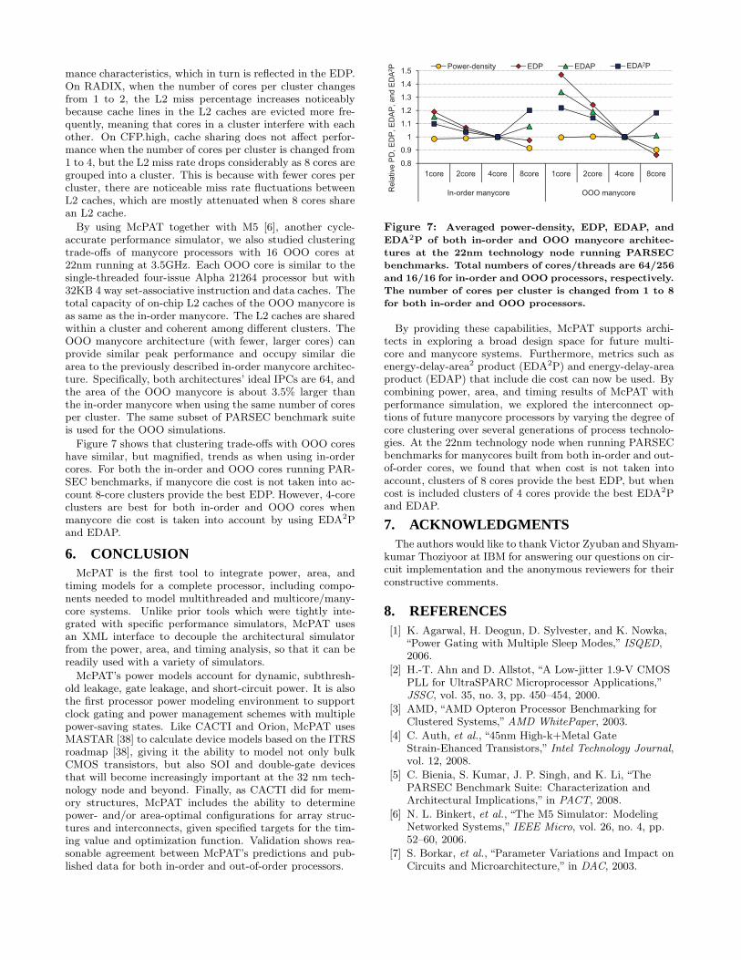
By using McPAT together with M5 [6], another cycle-accurate performance simulator, we also studied clusteringtrade-offs of manycore processors with 16 OOO cores at22nm running at 3.5GHz. Each OOO core is similar to thesingle-threaded four-issue Alpha 21264 processor but with32KB 4 way set-associative instruction and data caches. Thetotal capacity of on-chip L2 caches of the OOO manycore isas same as the in-order manycore. The L2 caches are sharedwithin a cluster and coherent among different clusters. TheOOO manycore architecture (with fewer, larger cores) canprovide similar peak performance and occupy similar diearea to the previously described in-order manycore architec-ture. Specifically, both architectures’ ideal IPCs are 64, andthe area of the OOO manycore is about 3.5% larger thanthe in-order manycore when using the same number of coresper cluster. The same subset of PARSEC benchmark suiteis used for the OOO simulations.
Figure 7 shows that clustering trade-offs with OOO coreshave similar, but magnified, trends as when using in-ordercores. For both the in-order and OOO cores running PAR-SEC benchmarks, if manycore die cost is not taken into ac-count 8-core clusters provide the best EDP. However, 4-coreclusters are best for both in-order and OOO cores whenmanycore die cost is taken into account by using EDA2Pand EDAP.
6. CONCLUSIONMcPAT is the first tool to integrate power, area, and
timing models for a complete processor, including compo-nents needed to model multithreaded and multicore/many-core systems. Unlike prior tools which were tightly inte-grated with specific performance simulators, McPAT usesan XML interface to decouple the architectural simulatorfrom the power, area, and timing analysis, so that it can bereadily used with a variety of simulators.
McPAT’s power models account for dynamic, subthresh-old leakage, gate leakage, and short-circuit power. It is alsothe first processor power modeling environment to supportclock gating and power management schemes with multiplepower-saving states. Like CACTI and Orion, McPAT usesMASTAR [38] to calculate device models based on the ITRSroadmap [38], giving it the ability to model not only bulkCMOS transistors, but also SOI and double-gate devicesthat will become increasingly important at the 32 nm tech-nology node and beyond. Finally, as CACTI did for mem-ory structures, McPAT includes the ability to determinepower- and/or area-optimal configurations for array struc-tures and interconnects, given specified targets for the tim-ing value and optimization function. Validation shows rea-sonable agreement between McPAT’s predictions and pub-lished data for both in-order and out-of-order processors.
1.4
1.5Power-density EDP EDAP EDA2PEDA2P
d E
DA
2P
1 1
1.2
1.3
1.4
1.5Power-density EDP EDAP EDA2PEDA2P
DA
P, a
nd
ED
A2P
0.9
1
1.1
1.2
1.3
1.4
1.5Power-density EDP EDAP EDA2PEDA2P
, E
DP
, E
DA
P, and E
DA
2P
0.8
0.9
1
1.1
1.2
1.3
1.4
1.5
1core 2core 4core 8core 1core 2core 4core 8core
Power-density EDP EDAP EDA2PEDA2P
lative
PD
, E
DP
, E
DA
P, a
nd
ED
A2P
0.8
0.9
1
1.1
1.2
1.3
1.4
1.5
1core 2core 4core 8core 1core 2core 4core 8core
In-order manycore OOO manycore
Power-density EDP EDAP EDA2PEDA2P
Re
lative
PD
, E
DP
, E
DA
P, a
nd
ED
A2P
0.8
0.9
1
1.1
1.2
1.3
1.4
1.5
1core 2core 4core 8core 1core 2core 4core 8core
In-order manycore OOO manycore
Power-density EDP EDAP EDA2PEDA2P
Re
lative
PD
, E
DP
, E
DA
P, a
nd
ED
A2P
0.8
0.9
1
1.1
1.2
1.3
1.4
1.5
1core 2core 4core 8core 1core 2core 4core 8core
In-order manycore OOO manycore
Power-density EDP EDAP EDA2PEDA2P
Re
lative
PD
, E
DP
, E
DA
P, a
nd
ED
A2P
Figure 7: Averaged power-density, EDP, EDAP, and
EDA2P of both in-order and OOO manycore architec-
tures at the 22nm technology node running PARSEC
benchmarks. Total numbers of cores/threads are 64/256
and 16/16 for in-order and OOO processors, respectively.
The number of cores per cluster is changed from 1 to 8
for both in-order and OOO processors.
By providing these capabilities, McPAT supports archi-tects in exploring a broad design space for future multi-core and manycore systems. Furthermore, metrics such asenergy-delay-area2 product (EDA2P) and energy-delay-areaproduct (EDAP) that include die cost can now be used. Bycombining power, area, and timing results of McPAT withperformance simulation, we explored the interconnect op-tions of future manycore processors by varying the degree ofcore clustering over several generations of process technolo-gies. At the 22nm technology node when running PARSECbenchmarks for manycores built from both in-order and out-of-order cores, we found that when cost is not taken intoaccount, clusters of 8 cores provide the best EDP, but whencost is included clusters of 4 cores provide the best EDA2Pand EDAP.
7. ACKNOWLEDGMENTSThe authors would like to thank Victor Zyuban and Shyam-
kumar Thoziyoor at IBM for answering our questions on cir-cuit implementation and the anonymous reviewers for theirconstructive comments.
8. REFERENCES[1] K. Agarwal, H. Deogun, D. Sylvester, and K. Nowka,
“Power Gating with Multiple Sleep Modes,” ISQED,2006.
[2] H.-T. Ahn and D. Allstot, “A Low-jitter 1.9-V CMOSPLL for UltraSPARC Microprocessor Applications,”JSSC, vol. 35, no. 3, pp. 450–454, 2000.
[3] AMD, “AMD Opteron Processor Benchmarking forClustered Systems,” AMD WhitePaper, 2003.
[4] C. Auth, et al., “45nm High-k+Metal GateStrain-Ehanced Transistors,” Intel Technology Journal,vol. 12, 2008.
[5] C. Bienia, S. Kumar, J. P. Singh, and K. Li, “ThePARSEC Benchmark Suite: Characterization andArchitectural Implications,” in PACT, 2008.
[6] N. L. Binkert, et al., “The M5 Simulator: ModelingNetworked Systems,” IEEE Micro, vol. 26, no. 4, pp.52–60, 2006.
[7] S. Borkar, et al., “Parameter Variations and Impact onCircuits and Microarchitecture,” in DAC, 2003.

[8] D. Brooks, V. Tiwari, and M. Martonosi, “Wattch: aframework for architectural-level power analysis andoptimizations,” in ISCA, 2000.
[9] D. Burger and T. M. Austin, “The simplescalar toolset, version 2.0,” SIGARCH Comput. Archit. News,vol. 25, no. 3, 1997.
[10] Denali, “Using Configurable Memory ControllerDesign IP with Encounter RTL Complier,” Cadence
CDNLive!, 2007.
[11] M. K. Gowan, L. L. Biro, and D. B. Jackson, “PowerConsiderations in the Design of the Alpha 21264Microprocessor,” in DAC, 1998.
[12] S. Gupta, S. Keckler, and D. Burger, “TechnologyIndependent Area and Delay Estimates forMicroprocessor Building Blocks,” UT Austin,Department of Computer Science,” Tech. Rep., 2000.
[13] J. L. Hennessy and D. A. Patterson, Computer
Architecture: A Quantitative Approach. 4th Edition,2007.
[14] J. L. Henning, “Performance Counters andDevelopment of SPEC CPU2006,” Computer
Architecture News, vol. 35, no. 1, 2007.
[15] G. Hinton, et al., “The Microarchitecture of thePentium 4 Processor,” Intel Technology Journal,vol. 1, 2001.
[16] Intel, “P6 Family of Processors Hardware Developer’sManual,” Intel White Paper, 1998.
[17] A. Jain, et al., “A 1.2 GHz Alpha Microprocessor with44.8 GB/s Chip Pin Bandwidth,” in ISSCC, 2001.
[18] A. Kahng, B. Li, L.-S. Peh, and K. Samadi, “ORION2.0: A Fast and Accurate NoC Power and Area Modelfor Early-Stage Design Space Exploration,” in DATE,2009.
[19] R. E. Kessler, “The Alpha 21264 Microprocessor,”IEEE Micro, vol. 19, no. 2, 1999.
[20] P. Kongetira, K. Aingaran, and K. Olukotun,“Niagara: A 32-Way Multithreaded Sparc Processor,”IEEE Micro, vol. 25, no. 2, 2005.
[21] D. Koufaty and D. T. Marr, “HyperthreadingTechnology in the Netburst Microarchitecture,” IEEE
Micro, vol. 23, no. 2, 2003.
[22] R. Kumar, V. Zyuban, and D. M. Tullsen,“Interconnections in Multi-Core Architectures:Understanding Mechanisms, Overheads and Scaling,”in ISCA, 2005.
[23] H. Lee, et al., “A 16Gb/s/link, 64GB/s BidirectionalAsymmetric Memory Interface,” JSSC, vol. 44, no. 4,2009.
[24] A. S. Leon, K. W. Tam, J. L. Shin, D. Weisner, andF. Schumacher, “A Power-Efficient High-Throughput32-Thread SPARC Processor,” JSSC, vol. 42, 2007.
[25] S. Li, J. Ahn, J. B. Brockman, and N. P. Jouppi,“McPAT 1.0: An Integrated Power, Area, and TimingModeling Framework for Multicore Architecture,” HPLabs, Tech. Rep. HPL-2009-206.
[26] C.-K. Luk, et al., “Pin: Building Customized ProgramAnalysis Tools with Dynamic Instrumentation,” inPLDI, Jun 2005.
[27] P. Mahoney, E. Fetzer, B. Doyle, and S. Naffziger,“Clock Distribution on a Dual-Core Multi-ThreadedItanium Family Processor,” in ISSCC, 2005.
[28] M. M. K. Martin, et al., “Multifacet’s GeneralExecution-driven Multiprocessor Simulator (GEMS)Toolset,” SIGARCH Computer Architecture News,vol. 33, no. 4, 2005.
[29] S. Mathew, et al., “A 4-GHz 300-mW 64-bit IntegerExecution ALU with Dual Supply Voltages in 90-nmCMOS,” JSSC, vol. 40, no. 1, 2005.
[30] A. Naveh, et al., “Power and Thermal Management inthe Intel Core Duo Processor,” Intel Technology
Journal, vol. 10, pp. 109–122, 2006.
[31] U. Nawathe, et al., “Implementation of an 8-Core,64-Thread, Power-Efficient SPARC Server on a Chip,”JSSC, vol. 43, no. 1, 2008.
[32] K. Nose and T. Sakurai, “Analysis and Future Trendof Short-circuit Power,” IEEE TCAD, vol. 19, no. 9,2000.
[33] S. Palacharla, N. P. Jouppi, and J. E. Smith,“Complexity-Effective Superscalar Processors,” inISCA, 1997.
[34] H. Pan, K. Asanovic, R. Cohn, and C.-K. Luk,“Controlling Program Execution through BinaryInstrumentation,” Computer Architecture News,vol. 33, no. 5, 2005.
[35] J. Rabaey, A. Chandrakasan, and B. Nikolic, Digital
Integrated Circuits: A Design Perspective; 2nd ed.,2003.
[36] A. F. Rodrigues, “Parametric Sizing for Processors,”Sandia National Laboratories,” Tech. Rep., 2007.
[37] S. Rusu, S. Tam, H. Muljono, D. Ayers, and J. Chang,“A Dual-Core Multi-Threaded Xeon Processor with16MB L3 Cache,” in ISSCC, 2006.
[38] Semiconductor Industries Association, “Model forAssessment of CMOS Technologies and Roadmaps(MASTAR),” 2007, http://www.itrs.net/models.html.
[39] T. Sherwood, E. Perelman, G. Hamerly, andB. Calder, “Automatically Characterizing Large ScaleProgram Behavior,” in ASPLOS, Oct 2002.
[40] Sun Microsystems, “OpenSPARC,”http://www.opensparc.net.
[41] S. Thoziyoor, J. Ahn, M. Monchiero, J. Brockman,and N. Jouppi, “A Comprehensive Memory ModelingTool and its Application to the Design and Analysis ofFuture Memory Hierarchies,” in ISCA, 2008.
[42] D. M. Tullsen, et al., “Exploiting Choice: InstructionFetch and Issue on an Implementable SimultaneousMultithreading Processor,” in ISCA, 1996.
[43] S. Vangal, N. Borkar, and A. Alvandpour, “A Six-port57GB/s Double-pumped Nonblocking Router Core,” inVLSI, June 2005.
[44] S. C. Woo, M. Ohara, E. Torrie, J. P. Singh, andA. Gupta, “The SPLASH-2 programs:Characterization and Methodological Considerations,”in ISCA, 1995.
[45] Y. Zhang, D. Parikh, K. Sankaranarayanan,K. Skadron, and M. Stan, “HotLeakage: ATemperature-Aware Model of Subthreshold and GateLeakage for Architects,” University of Virgina,Department of Computer Science,” Tech. Rep., 2003.