mcon -lc/lcg msep -lc scon -lc/lcg - iai-robot.co.jpme0329-8d).… · mcon -lc/lcg msep -lc scon...
TRANSCRIPT

IAI Corporation
Programming Manual
Eighth Edition
MCON -LC/LCGMSEP -LCSCON -LC/LCG


Please Read Before Use Thank you for purchasing our product. This Instruction Manual describes all necessary information to operate this product safely such as the operation procedure, structure and maintenance procedure. Before operation, read this manual carefully and fully understand it to operate this product safely. The DVD that comes with the product contains instruction manuals for IAI products. For a use of the products, print out or display on your personal computer the necessary pages of the applicable Instruction Manuals. After reading the Instruction Manuals, be sure to keep them in a convenient place easily accessible to the personnel using this product.
[Important] This Instruction Manual is original. This product is not to be used for any other purpose from what is noted in this Instruction Manual.
IAI shall not be liable whatsoever for any loss or damage arising from the result of using the product for any other purpose from what is noted in the manual.
The information contained in this Instruction Manual is subject to change without notice for the purpose of production improvement.
If you have any question or finding regarding the information contained in this Instruction Manual, contact our customer center or our sales office near you.
Using or copying all or a part of this Instruction Manual without permission is prohibited. The company names, names of products and trademarks of each company shown in the
sentences are registered trademarks.


Table of Contents Safety Guide ꞏꞏꞏꞏꞏꞏꞏꞏꞏꞏꞏꞏꞏꞏꞏꞏꞏꞏꞏꞏꞏꞏꞏꞏꞏꞏꞏꞏꞏꞏꞏꞏꞏꞏꞏꞏꞏꞏꞏꞏꞏꞏꞏꞏꞏꞏꞏꞏꞏꞏꞏꞏꞏꞏꞏꞏꞏꞏꞏꞏꞏꞏꞏꞏꞏꞏꞏꞏꞏꞏꞏꞏꞏꞏꞏꞏꞏꞏꞏꞏꞏꞏꞏꞏꞏꞏꞏꞏꞏꞏꞏꞏꞏꞏꞏꞏ1 1 Overviewꞏꞏꞏꞏꞏꞏꞏꞏꞏꞏꞏꞏꞏꞏꞏꞏꞏꞏꞏꞏꞏꞏꞏꞏꞏꞏꞏꞏꞏꞏꞏꞏꞏꞏꞏꞏꞏꞏꞏꞏꞏꞏꞏꞏꞏꞏꞏꞏꞏꞏꞏꞏꞏꞏꞏꞏꞏꞏꞏꞏꞏꞏꞏꞏꞏꞏꞏꞏꞏꞏꞏꞏꞏꞏꞏꞏꞏꞏꞏꞏꞏꞏꞏꞏꞏꞏꞏꞏꞏꞏꞏꞏꞏꞏꞏꞏꞏꞏꞏ9
2 Ladder Program ꞏꞏꞏꞏꞏꞏꞏꞏꞏꞏꞏꞏꞏꞏꞏꞏꞏꞏꞏꞏꞏꞏꞏꞏꞏꞏꞏꞏꞏꞏꞏꞏꞏꞏꞏꞏꞏꞏꞏꞏꞏꞏꞏꞏꞏꞏꞏꞏꞏꞏꞏꞏꞏꞏꞏꞏꞏꞏꞏꞏꞏꞏꞏꞏꞏꞏꞏꞏꞏꞏꞏꞏꞏꞏꞏꞏꞏꞏꞏꞏꞏꞏꞏꞏꞏꞏꞏ10 2.1 How to Create Description ꞏꞏꞏꞏꞏꞏꞏꞏꞏꞏꞏꞏꞏꞏꞏꞏꞏꞏꞏꞏꞏꞏꞏꞏꞏꞏꞏꞏꞏꞏꞏꞏꞏꞏꞏꞏꞏꞏꞏꞏꞏꞏꞏꞏꞏꞏꞏꞏꞏꞏꞏꞏꞏꞏꞏꞏꞏꞏꞏꞏꞏꞏꞏꞏꞏꞏꞏꞏꞏꞏꞏꞏꞏꞏꞏꞏ 10 2.2 Execution Orderꞏꞏꞏꞏꞏꞏꞏꞏꞏꞏꞏꞏꞏꞏꞏꞏꞏꞏꞏꞏꞏꞏꞏꞏꞏꞏꞏꞏꞏꞏꞏꞏꞏꞏꞏꞏꞏꞏꞏꞏꞏꞏꞏꞏꞏꞏꞏꞏꞏꞏꞏꞏꞏꞏꞏꞏꞏꞏꞏꞏꞏꞏꞏꞏꞏꞏꞏꞏꞏꞏꞏꞏꞏꞏꞏꞏꞏꞏꞏꞏꞏꞏꞏꞏꞏꞏꞏꞏꞏꞏ 10 2.3 Main Program and Subroutine Program ꞏꞏꞏꞏꞏꞏꞏꞏꞏꞏꞏꞏꞏꞏꞏꞏꞏꞏꞏꞏꞏꞏꞏꞏꞏꞏꞏꞏꞏꞏꞏꞏꞏꞏꞏꞏꞏꞏꞏꞏꞏꞏꞏꞏꞏꞏꞏꞏꞏꞏꞏꞏꞏꞏꞏꞏꞏꞏꞏꞏ11 2.4 Execution and Functions ꞏꞏꞏꞏꞏꞏꞏꞏꞏꞏꞏꞏꞏꞏꞏꞏꞏꞏꞏꞏꞏꞏꞏꞏꞏꞏꞏꞏꞏꞏꞏꞏꞏꞏꞏꞏꞏꞏꞏꞏꞏꞏꞏꞏꞏꞏꞏꞏꞏꞏꞏꞏꞏꞏꞏꞏꞏꞏꞏꞏꞏꞏꞏꞏꞏꞏꞏꞏꞏꞏꞏꞏꞏꞏꞏꞏꞏꞏꞏ11
2.4.1 I/O Refreshꞏꞏꞏꞏꞏꞏꞏꞏꞏꞏꞏꞏꞏꞏꞏꞏꞏꞏꞏꞏꞏꞏꞏꞏꞏꞏꞏꞏꞏꞏꞏꞏꞏꞏꞏꞏꞏꞏꞏꞏꞏꞏꞏꞏꞏꞏꞏꞏꞏꞏꞏꞏꞏꞏꞏꞏꞏꞏꞏꞏꞏꞏꞏꞏꞏꞏꞏꞏꞏꞏꞏꞏꞏꞏꞏꞏꞏꞏꞏꞏꞏꞏꞏꞏ 12 2.4.2 Constant Scanꞏꞏꞏꞏꞏꞏꞏꞏꞏꞏꞏꞏꞏꞏꞏꞏꞏꞏꞏꞏꞏꞏꞏꞏꞏꞏꞏꞏꞏꞏꞏꞏꞏꞏꞏꞏꞏꞏꞏꞏꞏꞏꞏꞏꞏꞏꞏꞏꞏꞏꞏꞏꞏꞏꞏꞏꞏꞏꞏꞏꞏꞏꞏꞏꞏꞏꞏꞏꞏꞏꞏꞏꞏꞏꞏꞏꞏꞏꞏꞏ 12 2.4.3 WDT (Watchdog Timer)ꞏꞏꞏꞏꞏꞏꞏꞏꞏꞏꞏꞏꞏꞏꞏꞏꞏꞏꞏꞏꞏꞏꞏꞏꞏꞏꞏꞏꞏꞏꞏꞏꞏꞏꞏꞏꞏꞏꞏꞏꞏꞏꞏꞏꞏꞏꞏꞏꞏꞏꞏꞏꞏꞏꞏꞏꞏꞏꞏꞏꞏꞏꞏꞏꞏꞏꞏ 12 2.4.4 Detection of Command Execution Error ꞏꞏꞏꞏꞏꞏꞏꞏꞏꞏꞏꞏꞏꞏꞏꞏꞏꞏꞏꞏꞏꞏꞏꞏꞏꞏꞏꞏꞏꞏꞏꞏꞏꞏꞏꞏꞏꞏꞏꞏꞏꞏꞏꞏꞏꞏꞏ 12
2.5 Available Numbers ꞏꞏꞏꞏꞏꞏꞏꞏꞏꞏꞏꞏꞏꞏꞏꞏꞏꞏꞏꞏꞏꞏꞏꞏꞏꞏꞏꞏꞏꞏꞏꞏꞏꞏꞏꞏꞏꞏꞏꞏꞏꞏꞏꞏꞏꞏꞏꞏꞏꞏꞏꞏꞏꞏꞏꞏꞏꞏꞏꞏꞏꞏꞏꞏꞏꞏꞏꞏꞏꞏꞏꞏꞏꞏꞏꞏꞏꞏꞏꞏꞏꞏꞏꞏꞏꞏ 13 2.6 Total Number of Stepsꞏꞏꞏꞏꞏꞏꞏꞏꞏꞏꞏꞏꞏꞏꞏꞏꞏꞏꞏꞏꞏꞏꞏꞏꞏꞏꞏꞏꞏꞏꞏꞏꞏꞏꞏꞏꞏꞏꞏꞏꞏꞏꞏꞏꞏꞏꞏꞏꞏꞏꞏꞏꞏꞏꞏꞏꞏꞏꞏꞏꞏꞏꞏꞏꞏꞏꞏꞏꞏꞏꞏꞏꞏꞏꞏꞏꞏꞏꞏꞏꞏꞏ 13
3 Input and Output (PIO) Assignment ꞏꞏꞏꞏꞏꞏꞏꞏꞏꞏꞏꞏꞏꞏꞏꞏꞏꞏꞏꞏꞏꞏꞏꞏꞏꞏꞏꞏꞏꞏꞏꞏꞏꞏꞏꞏꞏꞏꞏꞏꞏꞏꞏꞏꞏꞏꞏꞏꞏꞏꞏꞏꞏꞏꞏꞏꞏꞏꞏꞏꞏꞏ14 3.1 MSEP-LC, MCON-LC/LCG ꞏꞏꞏꞏꞏꞏꞏꞏꞏꞏꞏꞏꞏꞏꞏꞏꞏꞏꞏꞏꞏꞏꞏꞏꞏꞏꞏꞏꞏꞏꞏꞏꞏꞏꞏꞏꞏꞏꞏꞏꞏꞏꞏꞏꞏꞏꞏꞏꞏꞏꞏꞏꞏꞏꞏꞏꞏꞏꞏꞏꞏꞏꞏꞏꞏꞏꞏꞏꞏꞏꞏꞏꞏꞏꞏ 14 3.2 SCON-LC/LCGꞏꞏꞏꞏꞏꞏꞏꞏꞏꞏꞏꞏꞏꞏꞏꞏꞏꞏꞏꞏꞏꞏꞏꞏꞏꞏꞏꞏꞏꞏꞏꞏꞏꞏꞏꞏꞏꞏꞏꞏꞏꞏꞏꞏꞏꞏꞏꞏꞏꞏꞏꞏꞏꞏꞏꞏꞏꞏꞏꞏꞏꞏꞏꞏꞏꞏꞏꞏꞏꞏꞏꞏꞏꞏꞏꞏꞏꞏꞏꞏꞏꞏꞏꞏꞏꞏꞏꞏꞏꞏꞏ 17
3.2.1 PIOꞏꞏꞏꞏꞏꞏꞏꞏꞏꞏꞏꞏꞏꞏꞏꞏꞏꞏꞏꞏꞏꞏꞏꞏꞏꞏꞏꞏꞏꞏꞏꞏꞏꞏꞏꞏꞏꞏꞏꞏꞏꞏꞏꞏꞏꞏꞏꞏꞏꞏꞏꞏꞏꞏꞏꞏꞏꞏꞏꞏꞏꞏꞏꞏꞏꞏꞏꞏꞏꞏꞏꞏꞏꞏꞏꞏꞏꞏꞏꞏꞏꞏꞏꞏꞏꞏꞏꞏꞏꞏꞏꞏꞏꞏ 17 3.2.2 Fieldbusꞏꞏꞏꞏꞏꞏꞏꞏꞏꞏꞏꞏꞏꞏꞏꞏꞏꞏꞏꞏꞏꞏꞏꞏꞏꞏꞏꞏꞏꞏꞏꞏꞏꞏꞏꞏꞏꞏꞏꞏꞏꞏꞏꞏꞏꞏꞏꞏꞏꞏꞏꞏꞏꞏꞏꞏꞏꞏꞏꞏꞏꞏꞏꞏꞏꞏꞏꞏꞏꞏꞏꞏꞏꞏꞏꞏꞏꞏꞏꞏꞏꞏꞏꞏꞏꞏꞏꞏ 18
4 Memory List ꞏꞏꞏꞏꞏꞏꞏꞏꞏꞏꞏꞏꞏꞏꞏꞏꞏꞏꞏꞏꞏꞏꞏꞏꞏꞏꞏꞏꞏꞏꞏꞏꞏꞏꞏꞏꞏꞏꞏꞏꞏꞏꞏꞏꞏꞏꞏꞏꞏꞏꞏꞏꞏꞏꞏꞏꞏꞏꞏꞏꞏꞏꞏꞏꞏꞏꞏꞏꞏꞏꞏꞏꞏꞏꞏꞏꞏꞏꞏꞏꞏꞏꞏꞏꞏꞏꞏꞏꞏꞏꞏꞏꞏ19 4.1 Types of Memories and Points ꞏꞏꞏꞏꞏꞏꞏꞏꞏꞏꞏꞏꞏꞏꞏꞏꞏꞏꞏꞏꞏꞏꞏꞏꞏꞏꞏꞏꞏꞏꞏꞏꞏꞏꞏꞏꞏꞏꞏꞏꞏꞏꞏꞏꞏꞏꞏꞏꞏꞏꞏꞏꞏꞏꞏꞏꞏꞏꞏꞏꞏꞏꞏꞏꞏꞏꞏꞏꞏꞏꞏ 19 4.2 Memory ꞏꞏꞏꞏꞏꞏꞏꞏꞏꞏꞏꞏꞏꞏꞏꞏꞏꞏꞏꞏꞏꞏꞏꞏꞏꞏꞏꞏꞏꞏꞏꞏꞏꞏꞏꞏꞏꞏꞏꞏꞏꞏꞏꞏꞏꞏꞏꞏꞏꞏꞏꞏꞏꞏꞏꞏꞏꞏꞏꞏꞏꞏꞏꞏꞏꞏꞏꞏꞏꞏꞏꞏꞏꞏꞏꞏꞏꞏꞏꞏꞏꞏꞏꞏꞏꞏꞏꞏꞏꞏꞏꞏꞏꞏꞏꞏꞏꞏꞏꞏ 19
4.2.1 Input and Output Memory (X, Y) ꞏꞏꞏꞏꞏꞏꞏꞏꞏꞏꞏꞏꞏꞏꞏꞏꞏꞏꞏꞏꞏꞏꞏꞏꞏꞏꞏꞏꞏꞏꞏꞏꞏꞏꞏꞏꞏꞏꞏꞏꞏꞏꞏꞏꞏꞏꞏꞏꞏꞏꞏꞏꞏꞏꞏꞏ 19 4.2.2 Internal Relay (M)ꞏꞏꞏꞏꞏꞏꞏꞏꞏꞏꞏꞏꞏꞏꞏꞏꞏꞏꞏꞏꞏꞏꞏꞏꞏꞏꞏꞏꞏꞏꞏꞏꞏꞏꞏꞏꞏꞏꞏꞏꞏꞏꞏꞏꞏꞏꞏꞏꞏꞏꞏꞏꞏꞏꞏꞏꞏꞏꞏꞏꞏꞏꞏꞏꞏꞏꞏꞏꞏꞏꞏꞏꞏꞏꞏ 20 4.2.3 Special Relay (SM)ꞏꞏꞏꞏꞏꞏꞏꞏꞏꞏꞏꞏꞏꞏꞏꞏꞏꞏꞏꞏꞏꞏꞏꞏꞏꞏꞏꞏꞏꞏꞏꞏꞏꞏꞏꞏꞏꞏꞏꞏꞏꞏꞏꞏꞏꞏꞏꞏꞏꞏꞏꞏꞏꞏꞏꞏꞏꞏꞏꞏꞏꞏꞏꞏꞏꞏꞏꞏꞏꞏꞏꞏꞏꞏ 21 4.2.4 Data Register (D) ꞏꞏꞏꞏꞏꞏꞏꞏꞏꞏꞏꞏꞏꞏꞏꞏꞏꞏꞏꞏꞏꞏꞏꞏꞏꞏꞏꞏꞏꞏꞏꞏꞏꞏꞏꞏꞏꞏꞏꞏꞏꞏꞏꞏꞏꞏꞏꞏꞏꞏꞏꞏꞏꞏꞏꞏꞏꞏꞏꞏꞏꞏꞏꞏꞏꞏꞏꞏꞏꞏꞏꞏꞏꞏꞏꞏ 23 4.2.5 Special Register (SD)ꞏꞏꞏꞏꞏꞏꞏꞏꞏꞏꞏꞏꞏꞏꞏꞏꞏꞏꞏꞏꞏꞏꞏꞏꞏꞏꞏꞏꞏꞏꞏꞏꞏꞏꞏꞏꞏꞏꞏꞏꞏꞏꞏꞏꞏꞏꞏꞏꞏꞏꞏꞏꞏꞏꞏꞏꞏꞏꞏꞏꞏꞏꞏꞏꞏꞏꞏꞏꞏꞏꞏ 23 4.2.6 Index Register (IX) ꞏꞏꞏꞏꞏꞏꞏꞏꞏꞏꞏꞏꞏꞏꞏꞏꞏꞏꞏꞏꞏꞏꞏꞏꞏꞏꞏꞏꞏꞏꞏꞏꞏꞏꞏꞏꞏꞏꞏꞏꞏꞏꞏꞏꞏꞏꞏꞏꞏꞏꞏꞏꞏꞏꞏꞏꞏꞏꞏꞏꞏꞏꞏꞏꞏꞏꞏꞏꞏꞏꞏꞏꞏꞏ 24 4.2.7 Timer (T) ꞏꞏꞏꞏꞏꞏꞏꞏꞏꞏꞏꞏꞏꞏꞏꞏꞏꞏꞏꞏꞏꞏꞏꞏꞏꞏꞏꞏꞏꞏꞏꞏꞏꞏꞏꞏꞏꞏꞏꞏꞏꞏꞏꞏꞏꞏꞏꞏꞏꞏꞏꞏꞏꞏꞏꞏꞏꞏꞏꞏꞏꞏꞏꞏꞏꞏꞏꞏꞏꞏꞏꞏꞏꞏꞏꞏꞏꞏꞏꞏꞏꞏꞏꞏꞏꞏꞏ 25 4.2.8 Counter (C) ꞏꞏꞏꞏꞏꞏꞏꞏꞏꞏꞏꞏꞏꞏꞏꞏꞏꞏꞏꞏꞏꞏꞏꞏꞏꞏꞏꞏꞏꞏꞏꞏꞏꞏꞏꞏꞏꞏꞏꞏꞏꞏꞏꞏꞏꞏꞏꞏꞏꞏꞏꞏꞏꞏꞏꞏꞏꞏꞏꞏꞏꞏꞏꞏꞏꞏꞏꞏꞏꞏꞏꞏꞏꞏꞏꞏꞏꞏꞏꞏꞏꞏꞏ 26 4.2.9 Label (L) ꞏꞏꞏꞏꞏꞏꞏꞏꞏꞏꞏꞏꞏꞏꞏꞏꞏꞏꞏꞏꞏꞏꞏꞏꞏꞏꞏꞏꞏꞏꞏꞏꞏꞏꞏꞏꞏꞏꞏꞏꞏꞏꞏꞏꞏꞏꞏꞏꞏꞏꞏꞏꞏꞏꞏꞏꞏꞏꞏꞏꞏꞏꞏꞏꞏꞏꞏꞏꞏꞏꞏꞏꞏꞏꞏꞏꞏꞏꞏꞏꞏꞏꞏꞏꞏꞏꞏ 26 4.2.10 Special Relay (SM)ꞏꞏꞏꞏꞏꞏꞏꞏꞏꞏꞏꞏꞏꞏꞏꞏꞏꞏꞏꞏꞏꞏꞏꞏꞏꞏꞏꞏꞏꞏꞏꞏꞏꞏꞏꞏꞏꞏꞏꞏꞏꞏꞏꞏꞏꞏꞏꞏꞏꞏꞏꞏꞏꞏꞏꞏꞏꞏꞏꞏꞏꞏꞏꞏꞏꞏꞏꞏꞏꞏꞏꞏꞏꞏ 27
5 Command Constructionꞏꞏꞏꞏꞏꞏꞏꞏꞏꞏꞏꞏꞏꞏꞏꞏꞏꞏꞏꞏꞏꞏꞏꞏꞏꞏꞏꞏꞏꞏꞏꞏꞏꞏꞏꞏꞏꞏꞏꞏꞏꞏꞏꞏꞏꞏꞏꞏꞏꞏꞏꞏꞏꞏꞏꞏꞏꞏꞏꞏꞏꞏꞏꞏꞏꞏꞏꞏꞏꞏꞏꞏꞏꞏꞏꞏꞏꞏ28 5.1 Show to Set up Dataꞏꞏꞏꞏꞏꞏꞏꞏꞏꞏꞏꞏꞏꞏꞏꞏꞏꞏꞏꞏꞏꞏꞏꞏꞏꞏꞏꞏꞏꞏꞏꞏꞏꞏꞏꞏꞏꞏꞏꞏꞏꞏꞏꞏꞏꞏꞏꞏꞏꞏꞏꞏꞏꞏꞏꞏꞏꞏꞏꞏꞏꞏꞏꞏꞏꞏꞏꞏꞏꞏꞏꞏꞏꞏꞏꞏꞏꞏꞏꞏꞏꞏꞏꞏ 29 5.2 Condition of Command Executionꞏꞏꞏꞏꞏꞏꞏꞏꞏꞏꞏꞏꞏꞏꞏꞏꞏꞏꞏꞏꞏꞏꞏꞏꞏꞏꞏꞏꞏꞏꞏꞏꞏꞏꞏꞏꞏꞏꞏꞏꞏꞏꞏꞏꞏꞏꞏꞏꞏꞏꞏꞏꞏꞏꞏꞏꞏꞏꞏꞏꞏꞏꞏꞏꞏꞏꞏ 31 5.3 Number of Steps ꞏꞏꞏꞏꞏꞏꞏꞏꞏꞏꞏꞏꞏꞏꞏꞏꞏꞏꞏꞏꞏꞏꞏꞏꞏꞏꞏꞏꞏꞏꞏꞏꞏꞏꞏꞏꞏꞏꞏꞏꞏꞏꞏꞏꞏꞏꞏꞏꞏꞏꞏꞏꞏꞏꞏꞏꞏꞏꞏꞏꞏꞏꞏꞏꞏꞏꞏꞏꞏꞏꞏꞏꞏꞏꞏꞏꞏꞏꞏꞏꞏꞏꞏꞏꞏꞏꞏꞏꞏ 32
6 How to View Commands ꞏꞏꞏꞏꞏꞏꞏꞏꞏꞏꞏꞏꞏꞏꞏꞏꞏꞏꞏꞏꞏꞏꞏꞏꞏꞏꞏꞏꞏꞏꞏꞏꞏꞏꞏꞏꞏꞏꞏꞏꞏꞏꞏꞏꞏꞏꞏꞏꞏꞏꞏꞏꞏꞏꞏꞏꞏꞏꞏꞏꞏꞏꞏꞏꞏꞏꞏꞏꞏꞏꞏꞏꞏꞏꞏꞏ33
7 Commands Purposing for Axis Control, etc. (DFC Command) ꞏꞏꞏꞏꞏꞏꞏꞏꞏꞏꞏꞏꞏꞏꞏꞏꞏꞏꞏꞏꞏꞏꞏꞏꞏꞏꞏꞏ34 7.1 Registration of DFC ꞏꞏꞏꞏꞏꞏꞏꞏꞏꞏꞏꞏꞏꞏꞏꞏꞏꞏꞏꞏꞏꞏꞏꞏꞏꞏꞏꞏꞏꞏꞏꞏꞏꞏꞏꞏꞏꞏꞏꞏꞏꞏꞏꞏꞏꞏꞏꞏꞏꞏꞏꞏꞏꞏꞏꞏꞏꞏꞏꞏꞏꞏꞏꞏꞏꞏꞏꞏꞏꞏꞏꞏꞏꞏꞏꞏꞏꞏꞏꞏꞏꞏꞏꞏꞏ 34 7.2 Axis Control Command (DFC0-5) ꞏꞏꞏꞏꞏꞏꞏꞏꞏꞏꞏꞏꞏꞏꞏꞏꞏꞏꞏꞏꞏꞏꞏꞏꞏꞏꞏꞏꞏꞏꞏꞏꞏꞏꞏꞏꞏꞏꞏꞏꞏꞏꞏꞏꞏꞏꞏꞏꞏꞏꞏꞏꞏꞏꞏꞏꞏꞏꞏꞏꞏꞏꞏꞏꞏꞏꞏ 36 7.3 Command Transfer Command between Axis and Driver (DFC8) ꞏꞏꞏꞏꞏꞏꞏꞏꞏꞏꞏꞏꞏꞏꞏꞏꞏꞏꞏꞏꞏꞏꞏꞏꞏꞏꞏ 38 7.4 Fieldbus Communication Command (DFC9)ꞏꞏꞏꞏꞏꞏꞏꞏꞏꞏꞏꞏꞏꞏꞏꞏꞏꞏꞏꞏꞏꞏꞏꞏꞏꞏꞏꞏꞏꞏꞏꞏꞏꞏꞏꞏꞏꞏꞏꞏꞏꞏꞏꞏꞏꞏꞏꞏꞏꞏꞏꞏꞏ 40 7.5 Positioning Command (DFC10-15)ꞏꞏꞏꞏꞏꞏꞏꞏꞏꞏꞏꞏꞏꞏꞏꞏꞏꞏꞏꞏꞏꞏꞏꞏꞏꞏꞏꞏꞏꞏꞏꞏꞏꞏꞏꞏꞏꞏꞏꞏꞏꞏꞏꞏꞏꞏꞏꞏꞏꞏꞏꞏꞏꞏꞏꞏꞏꞏꞏꞏꞏꞏꞏꞏꞏ 41
8 Basic Command ꞏꞏꞏꞏꞏꞏꞏꞏꞏꞏꞏꞏꞏꞏꞏꞏꞏꞏꞏꞏꞏꞏꞏꞏꞏꞏꞏꞏꞏꞏꞏꞏꞏꞏꞏꞏꞏꞏꞏꞏꞏꞏꞏꞏꞏꞏꞏꞏꞏꞏꞏꞏꞏꞏꞏꞏꞏꞏꞏꞏꞏꞏꞏꞏꞏꞏꞏꞏꞏꞏꞏꞏꞏꞏꞏꞏꞏꞏꞏꞏꞏꞏꞏꞏꞏꞏꞏ43 8.1 Basic Command Listꞏꞏꞏꞏꞏꞏꞏꞏꞏꞏꞏꞏꞏꞏꞏꞏꞏꞏꞏꞏꞏꞏꞏꞏꞏꞏꞏꞏꞏꞏꞏꞏꞏꞏꞏꞏꞏꞏꞏꞏꞏꞏꞏꞏꞏꞏꞏꞏꞏꞏꞏꞏꞏꞏꞏꞏꞏꞏꞏꞏꞏꞏꞏꞏꞏꞏꞏꞏꞏꞏꞏꞏꞏꞏꞏꞏꞏꞏꞏꞏꞏꞏꞏꞏ 43 8.2 Explanation of the command ꞏꞏꞏꞏꞏꞏꞏꞏꞏꞏꞏꞏꞏꞏꞏꞏꞏꞏꞏꞏꞏꞏꞏꞏꞏꞏꞏꞏꞏꞏꞏꞏꞏꞏꞏꞏꞏꞏꞏꞏꞏꞏꞏꞏꞏꞏꞏꞏꞏꞏꞏꞏꞏꞏꞏꞏꞏꞏꞏꞏꞏꞏꞏꞏꞏꞏꞏꞏꞏꞏꞏꞏꞏ 44
8.2.1 Contact Command ꞏꞏꞏꞏꞏꞏꞏꞏꞏꞏꞏꞏꞏꞏꞏꞏꞏꞏꞏꞏꞏꞏꞏꞏꞏꞏꞏꞏꞏꞏꞏꞏꞏꞏꞏꞏꞏꞏꞏꞏꞏꞏꞏꞏꞏꞏꞏꞏꞏꞏꞏꞏꞏꞏꞏꞏꞏꞏꞏꞏꞏꞏꞏꞏꞏꞏꞏꞏꞏꞏꞏꞏꞏꞏ 44 8.2.2 Connect Command ꞏꞏꞏꞏꞏꞏꞏꞏꞏꞏꞏꞏꞏꞏꞏꞏꞏꞏꞏꞏꞏꞏꞏꞏꞏꞏꞏꞏꞏꞏꞏꞏꞏꞏꞏꞏꞏꞏꞏꞏꞏꞏꞏꞏꞏꞏꞏꞏꞏꞏꞏꞏꞏꞏꞏꞏꞏꞏꞏꞏꞏꞏꞏꞏꞏꞏꞏꞏꞏꞏꞏꞏꞏ 46 8.2.3 Output Commandꞏꞏꞏꞏꞏꞏꞏꞏꞏꞏꞏꞏꞏꞏꞏꞏꞏꞏꞏꞏꞏꞏꞏꞏꞏꞏꞏꞏꞏꞏꞏꞏꞏꞏꞏꞏꞏꞏꞏꞏꞏꞏꞏꞏꞏꞏꞏꞏꞏꞏꞏꞏꞏꞏꞏꞏꞏꞏꞏꞏꞏꞏꞏꞏꞏꞏꞏꞏꞏꞏꞏꞏꞏꞏꞏꞏ 48 8.2.4 Termination Command ꞏꞏꞏꞏꞏꞏꞏꞏꞏꞏꞏꞏꞏꞏꞏꞏꞏꞏꞏꞏꞏꞏꞏꞏꞏꞏꞏꞏꞏꞏꞏꞏꞏꞏꞏꞏꞏꞏꞏꞏꞏꞏꞏꞏꞏꞏꞏꞏꞏꞏꞏꞏꞏꞏꞏꞏꞏꞏꞏꞏꞏꞏꞏꞏꞏꞏꞏꞏꞏ 52

9 Practical Command ꞏꞏꞏꞏꞏꞏꞏꞏꞏꞏꞏꞏꞏꞏꞏꞏꞏꞏꞏꞏꞏꞏꞏꞏꞏꞏꞏꞏꞏꞏꞏꞏꞏꞏꞏꞏꞏꞏꞏꞏꞏꞏꞏꞏꞏꞏꞏꞏꞏꞏꞏꞏꞏꞏꞏꞏꞏꞏꞏꞏꞏꞏꞏꞏꞏꞏꞏꞏꞏꞏꞏꞏꞏꞏꞏꞏꞏꞏꞏꞏꞏꞏ53 9.1 Practical Command List ꞏꞏꞏꞏꞏꞏꞏꞏꞏꞏꞏꞏꞏꞏꞏꞏꞏꞏꞏꞏꞏꞏꞏꞏꞏꞏꞏꞏꞏꞏꞏꞏꞏꞏꞏꞏꞏꞏꞏꞏꞏꞏꞏꞏꞏꞏꞏꞏꞏꞏꞏꞏꞏꞏꞏꞏꞏꞏꞏꞏꞏꞏꞏꞏꞏꞏꞏꞏꞏꞏꞏꞏꞏꞏꞏꞏꞏꞏꞏ 53 9.2 Explanation of the Commandꞏꞏꞏꞏꞏꞏꞏꞏꞏꞏꞏꞏꞏꞏꞏꞏꞏꞏꞏꞏꞏꞏꞏꞏꞏꞏꞏꞏꞏꞏꞏꞏꞏꞏꞏꞏꞏꞏꞏꞏꞏꞏꞏꞏꞏꞏꞏꞏꞏꞏꞏꞏꞏꞏꞏꞏꞏꞏꞏꞏꞏꞏꞏꞏꞏꞏꞏꞏꞏꞏꞏꞏꞏ 55
9.2.1 Data Comparison Command ꞏꞏꞏꞏꞏꞏꞏꞏꞏꞏꞏꞏꞏꞏꞏꞏꞏꞏꞏꞏꞏꞏꞏꞏꞏꞏꞏꞏꞏꞏꞏꞏꞏꞏꞏꞏꞏꞏꞏꞏꞏꞏꞏꞏꞏꞏꞏꞏꞏꞏꞏꞏꞏꞏꞏꞏꞏꞏꞏꞏꞏ 55 9.2.2 Arithmetic Operation Commandꞏꞏꞏꞏꞏꞏꞏꞏꞏꞏꞏꞏꞏꞏꞏꞏꞏꞏꞏꞏꞏꞏꞏꞏꞏꞏꞏꞏꞏꞏꞏꞏꞏꞏꞏꞏꞏꞏꞏꞏꞏꞏꞏꞏꞏꞏꞏꞏꞏꞏꞏꞏꞏꞏꞏꞏꞏ 56 9.2.3 BCD – BIN Conversion Command ꞏꞏꞏꞏꞏꞏꞏꞏꞏꞏꞏꞏꞏꞏꞏꞏꞏꞏꞏꞏꞏꞏꞏꞏꞏꞏꞏꞏꞏꞏꞏꞏꞏꞏꞏꞏꞏꞏꞏꞏꞏꞏꞏꞏꞏꞏꞏꞏꞏꞏꞏꞏꞏ 69 9.2.4 Transfer Commandꞏꞏꞏꞏꞏꞏꞏꞏꞏꞏꞏꞏꞏꞏꞏꞏꞏꞏꞏꞏꞏꞏꞏꞏꞏꞏꞏꞏꞏꞏꞏꞏꞏꞏꞏꞏꞏꞏꞏꞏꞏꞏꞏꞏꞏꞏꞏꞏꞏꞏꞏꞏꞏꞏꞏꞏꞏꞏꞏꞏꞏꞏꞏꞏꞏꞏꞏꞏꞏꞏꞏꞏꞏꞏ 71 9.2.5 Divergence Commandꞏꞏꞏꞏꞏꞏꞏꞏꞏꞏꞏꞏꞏꞏꞏꞏꞏꞏꞏꞏꞏꞏꞏꞏꞏꞏꞏꞏꞏꞏꞏꞏꞏꞏꞏꞏꞏꞏꞏꞏꞏꞏꞏꞏꞏꞏꞏꞏꞏꞏꞏꞏꞏꞏꞏꞏꞏꞏꞏꞏꞏꞏꞏꞏꞏꞏꞏꞏꞏ 76 9.2.6 Logical Operation Command ꞏꞏꞏꞏꞏꞏꞏꞏꞏꞏꞏꞏꞏꞏꞏꞏꞏꞏꞏꞏꞏꞏꞏꞏꞏꞏꞏꞏꞏꞏꞏꞏꞏꞏꞏꞏꞏꞏꞏꞏꞏꞏꞏꞏꞏꞏꞏꞏꞏꞏꞏꞏꞏꞏꞏꞏꞏꞏꞏꞏ 81 9.2.7 Rotation Commandꞏꞏꞏꞏꞏꞏꞏꞏꞏꞏꞏꞏꞏꞏꞏꞏꞏꞏꞏꞏꞏꞏꞏꞏꞏꞏꞏꞏꞏꞏꞏꞏꞏꞏꞏꞏꞏꞏꞏꞏꞏꞏꞏꞏꞏꞏꞏꞏꞏꞏꞏꞏꞏꞏꞏꞏꞏꞏꞏꞏꞏꞏꞏꞏꞏꞏꞏꞏꞏꞏꞏꞏꞏ 90 9.2.8 Shift Commandꞏꞏꞏꞏꞏꞏꞏꞏꞏꞏꞏꞏꞏꞏꞏꞏꞏꞏꞏꞏꞏꞏꞏꞏꞏꞏꞏꞏꞏꞏꞏꞏꞏꞏꞏꞏꞏꞏꞏꞏꞏꞏꞏꞏꞏꞏꞏꞏꞏꞏꞏꞏꞏꞏꞏꞏꞏꞏꞏꞏꞏꞏꞏꞏꞏꞏꞏꞏꞏꞏꞏꞏꞏꞏꞏꞏꞏꞏ 95 9.2.9 Data Process Command ꞏꞏꞏꞏꞏꞏꞏꞏꞏꞏꞏꞏꞏꞏꞏꞏꞏꞏꞏꞏꞏꞏꞏꞏꞏꞏꞏꞏꞏꞏꞏꞏꞏꞏꞏꞏꞏꞏꞏꞏꞏꞏꞏꞏꞏꞏꞏꞏꞏꞏꞏꞏꞏꞏꞏꞏꞏꞏꞏꞏꞏꞏꞏꞏꞏ101 9.2.10 FIFO Command ꞏꞏꞏꞏꞏꞏꞏꞏꞏꞏꞏꞏꞏꞏꞏꞏꞏꞏꞏꞏꞏꞏꞏꞏꞏꞏꞏꞏꞏꞏꞏꞏꞏꞏꞏꞏꞏꞏꞏꞏꞏꞏꞏꞏꞏꞏꞏꞏꞏꞏꞏꞏꞏꞏꞏꞏꞏꞏꞏꞏꞏꞏꞏꞏꞏꞏꞏꞏꞏꞏꞏꞏꞏꞏꞏꞏ108 9.2.11 Loop Command ꞏꞏꞏꞏꞏꞏꞏꞏꞏꞏꞏꞏꞏꞏꞏꞏꞏꞏꞏꞏꞏꞏꞏꞏꞏꞏꞏꞏꞏꞏꞏꞏꞏꞏꞏꞏꞏꞏꞏꞏꞏꞏꞏꞏꞏꞏꞏꞏꞏꞏꞏꞏꞏꞏꞏꞏꞏꞏꞏꞏꞏꞏꞏꞏꞏꞏꞏꞏꞏꞏꞏꞏꞏꞏꞏꞏ 112 9.2.12 Carry Flag Commandꞏꞏꞏꞏꞏꞏꞏꞏꞏꞏꞏꞏꞏꞏꞏꞏꞏꞏꞏꞏꞏꞏꞏꞏꞏꞏꞏꞏꞏꞏꞏꞏꞏꞏꞏꞏꞏꞏꞏꞏꞏꞏꞏꞏꞏꞏꞏꞏꞏꞏꞏꞏꞏꞏꞏꞏꞏꞏꞏꞏꞏꞏꞏꞏꞏꞏꞏꞏꞏ 114
10 Appendix ꞏꞏꞏꞏꞏꞏꞏꞏꞏꞏꞏꞏꞏꞏꞏꞏꞏꞏꞏꞏꞏꞏꞏꞏꞏꞏꞏꞏꞏꞏꞏꞏꞏꞏꞏꞏꞏꞏꞏꞏꞏꞏꞏꞏꞏꞏꞏꞏꞏꞏꞏꞏꞏꞏꞏꞏꞏꞏꞏꞏꞏꞏꞏꞏꞏꞏꞏꞏꞏꞏꞏꞏꞏꞏꞏꞏꞏꞏꞏꞏꞏꞏꞏꞏꞏꞏꞏꞏꞏꞏꞏꞏꞏ 115 10.1 Axis Control Command (DFC0 to 5) Address Mapꞏꞏꞏꞏꞏꞏꞏꞏꞏꞏꞏꞏꞏꞏꞏꞏꞏꞏꞏꞏꞏꞏꞏꞏꞏꞏꞏꞏꞏꞏꞏꞏꞏꞏꞏꞏꞏꞏꞏꞏꞏꞏꞏꞏꞏ 115
10.1.1 Address Construction by IO Pattern (Operation Mode) ꞏꞏꞏꞏꞏꞏꞏꞏꞏꞏꞏꞏꞏꞏꞏꞏꞏꞏꞏꞏꞏꞏꞏꞏꞏꞏ 115 10.1.2 Control Signals of Positioner 1/Simple Direct Mode ꞏꞏꞏꞏꞏꞏꞏꞏꞏꞏꞏꞏꞏꞏꞏꞏꞏꞏꞏꞏꞏꞏꞏꞏꞏꞏꞏꞏꞏꞏꞏꞏ 117 10.1.3 Control Signals for Positioner 2 Modeꞏꞏꞏꞏꞏꞏꞏꞏꞏꞏꞏꞏꞏꞏꞏꞏꞏꞏꞏꞏꞏꞏꞏꞏꞏꞏꞏꞏꞏꞏꞏꞏꞏꞏꞏꞏꞏꞏꞏꞏꞏꞏꞏꞏꞏꞏꞏꞏꞏꞏ122 10.1.4 Control Signals for Positioner 3 Modeꞏꞏꞏꞏꞏꞏꞏꞏꞏꞏꞏꞏꞏꞏꞏꞏꞏꞏꞏꞏꞏꞏꞏꞏꞏꞏꞏꞏꞏꞏꞏꞏꞏꞏꞏꞏꞏꞏꞏꞏꞏꞏꞏꞏꞏꞏꞏꞏꞏꞏ126 10.1.5 Control Signals for Direct Indication Mode. ꞏꞏꞏꞏꞏꞏꞏꞏꞏꞏꞏꞏꞏꞏꞏꞏꞏꞏꞏꞏꞏꞏꞏꞏꞏꞏꞏꞏꞏꞏꞏꞏꞏꞏꞏꞏꞏꞏꞏꞏꞏꞏ129
10.2 I/O Signal Control and Functions of Axis Control Command (DFC0 to 5) ꞏꞏꞏꞏꞏꞏꞏꞏꞏꞏꞏꞏꞏꞏꞏ136 10.2.1 Controller Ready (CRDY) Inputꞏꞏꞏꞏꞏꞏꞏꞏꞏꞏꞏꞏꞏꞏꞏꞏꞏꞏꞏꞏꞏꞏꞏꞏꞏꞏꞏꞏꞏꞏꞏꞏꞏꞏꞏꞏꞏꞏꞏꞏꞏꞏꞏꞏꞏꞏꞏꞏꞏꞏꞏꞏꞏꞏꞏꞏꞏꞏ136 10.2.2 Emergency Stop (EMGS) input ꞏꞏꞏꞏꞏꞏꞏꞏꞏꞏꞏꞏꞏꞏꞏꞏꞏꞏꞏꞏꞏꞏꞏꞏꞏꞏꞏꞏꞏꞏꞏꞏꞏꞏꞏꞏꞏꞏꞏꞏꞏꞏꞏꞏꞏꞏꞏꞏꞏꞏꞏꞏꞏꞏꞏꞏꞏꞏ136 10.2.3 Alarm (ALM) Input ꞏꞏꞏꞏꞏꞏꞏꞏꞏꞏꞏꞏꞏꞏꞏꞏꞏꞏꞏꞏꞏꞏꞏꞏꞏꞏꞏꞏꞏꞏꞏꞏꞏꞏꞏꞏꞏꞏꞏꞏꞏꞏꞏꞏꞏꞏꞏꞏꞏꞏꞏꞏꞏꞏꞏꞏꞏꞏꞏꞏꞏꞏꞏꞏꞏꞏꞏꞏꞏꞏꞏꞏꞏꞏ136 10.2.4 Reset (RES) Output ꞏꞏꞏꞏꞏꞏꞏꞏꞏꞏꞏꞏꞏꞏꞏꞏꞏꞏꞏꞏꞏꞏꞏꞏꞏꞏꞏꞏꞏꞏꞏꞏꞏꞏꞏꞏꞏꞏꞏꞏꞏꞏꞏꞏꞏꞏꞏꞏꞏꞏꞏꞏꞏꞏꞏꞏꞏꞏꞏꞏꞏꞏꞏꞏꞏꞏꞏꞏꞏꞏꞏꞏ136 10.2.5 Servo ON Command (SON) Operation Ready (SV) Input ꞏꞏꞏꞏꞏꞏꞏꞏꞏꞏꞏꞏꞏꞏꞏꞏꞏꞏꞏꞏꞏꞏꞏꞏ137 10.2.6 Home Return (HOME) Home Return Complection (HEND) Inputꞏꞏꞏꞏꞏꞏꞏꞏꞏꞏꞏꞏꞏꞏꞏ137 10.2.7 Positioning Start (CSTR) Output ꞏꞏꞏꞏꞏꞏꞏꞏꞏꞏꞏꞏꞏꞏꞏꞏꞏꞏꞏꞏꞏꞏꞏꞏꞏꞏꞏꞏꞏꞏꞏꞏꞏꞏꞏꞏꞏꞏꞏꞏꞏꞏꞏꞏꞏꞏꞏꞏꞏꞏꞏꞏꞏꞏꞏꞏ138 10.2.8 Moving Signal (MOVE) Input ꞏꞏꞏꞏꞏꞏꞏꞏꞏꞏꞏꞏꞏꞏꞏꞏꞏꞏꞏꞏꞏꞏꞏꞏꞏꞏꞏꞏꞏꞏꞏꞏꞏꞏꞏꞏꞏꞏꞏꞏꞏꞏꞏꞏꞏꞏꞏꞏꞏꞏꞏꞏꞏꞏꞏꞏꞏꞏꞏ138 10.2.9 Positioning Complection Signal (PEND) Input ꞏꞏꞏꞏꞏꞏꞏꞏꞏꞏꞏꞏꞏꞏꞏꞏꞏꞏꞏꞏꞏꞏꞏꞏꞏꞏꞏꞏꞏꞏꞏꞏꞏꞏꞏꞏꞏꞏꞏ138 10.2.10 Pause Output ꞏꞏꞏꞏꞏꞏꞏꞏꞏꞏꞏꞏꞏꞏꞏꞏꞏꞏꞏꞏꞏꞏꞏꞏꞏꞏꞏꞏꞏꞏꞏꞏꞏꞏꞏꞏꞏꞏꞏꞏꞏꞏꞏꞏꞏꞏꞏꞏꞏꞏꞏꞏꞏꞏꞏꞏꞏꞏꞏꞏꞏꞏꞏꞏꞏꞏꞏꞏꞏꞏꞏꞏꞏꞏꞏꞏꞏꞏꞏ139 10.2.11 Zone1 (ZONE1) Zone2 (ZONE2) Input ꞏꞏꞏꞏꞏꞏꞏꞏꞏꞏꞏꞏꞏꞏꞏꞏꞏꞏꞏꞏꞏꞏꞏꞏꞏꞏꞏꞏꞏꞏꞏꞏꞏꞏꞏꞏꞏꞏꞏꞏꞏꞏꞏꞏꞏꞏ139 10.2.12 + Jog (JOG+) –JOG (JOG-) Outputꞏꞏꞏꞏꞏꞏꞏꞏꞏꞏꞏꞏꞏꞏꞏꞏꞏꞏꞏꞏꞏꞏꞏꞏꞏꞏꞏꞏꞏꞏꞏꞏꞏꞏꞏꞏꞏꞏꞏꞏꞏꞏꞏꞏꞏꞏꞏꞏꞏꞏꞏ139 10.2.13 Incremental Command (INC) Output ꞏꞏꞏꞏꞏꞏꞏꞏꞏꞏꞏꞏꞏꞏꞏꞏꞏꞏꞏꞏꞏꞏꞏꞏꞏꞏꞏꞏꞏꞏꞏꞏꞏꞏꞏꞏꞏꞏꞏꞏꞏꞏꞏꞏꞏꞏꞏꞏꞏ140 10.2.14 Jog/inching Switching (JISL) Output ꞏꞏꞏꞏꞏꞏꞏꞏꞏꞏꞏꞏꞏꞏꞏꞏꞏꞏꞏꞏꞏꞏꞏꞏꞏꞏꞏꞏꞏꞏꞏꞏꞏꞏꞏꞏꞏꞏꞏꞏꞏꞏꞏꞏꞏꞏꞏꞏꞏꞏ140 10.2.15 Brake Release (BKRL) Output ꞏꞏꞏꞏꞏꞏꞏꞏꞏꞏꞏꞏꞏꞏꞏꞏꞏꞏꞏꞏꞏꞏꞏꞏꞏꞏꞏꞏꞏꞏꞏꞏꞏꞏꞏꞏꞏꞏꞏꞏꞏꞏꞏꞏꞏꞏꞏꞏꞏꞏꞏꞏꞏꞏꞏꞏꞏ140 10.2.16 Push-motion Specification (PUSH) Output ꞏꞏꞏꞏꞏꞏꞏꞏꞏꞏꞏꞏꞏꞏꞏꞏꞏꞏꞏꞏꞏꞏꞏꞏꞏꞏꞏꞏꞏꞏꞏꞏꞏꞏꞏꞏꞏꞏꞏꞏꞏꞏ141 10.2.17 Push Direction Specification (DIR) Output ꞏꞏꞏꞏꞏꞏꞏꞏꞏꞏꞏꞏꞏꞏꞏꞏꞏꞏꞏꞏꞏꞏꞏꞏꞏꞏꞏꞏꞏꞏꞏꞏꞏꞏꞏꞏꞏꞏꞏꞏꞏꞏ142 10.2.18 Pressing and a Miss (PSFL) Input ꞏꞏꞏꞏꞏꞏꞏꞏꞏꞏꞏꞏꞏꞏꞏꞏꞏꞏꞏꞏꞏꞏꞏꞏꞏꞏꞏꞏꞏꞏꞏꞏꞏꞏꞏꞏꞏꞏꞏꞏꞏꞏꞏꞏꞏꞏꞏꞏꞏꞏꞏꞏ142 10.2.19 Light Error Alarm (ALML) Inputꞏꞏꞏꞏꞏꞏꞏꞏꞏꞏꞏꞏꞏꞏꞏꞏꞏꞏꞏꞏꞏꞏꞏꞏꞏꞏꞏꞏꞏꞏꞏꞏꞏꞏꞏꞏꞏꞏꞏꞏꞏꞏꞏꞏꞏꞏꞏꞏꞏꞏꞏꞏꞏꞏꞏꞏꞏ142 10.2.20 Reset (RES) Inputꞏꞏꞏꞏꞏꞏꞏꞏꞏꞏꞏꞏꞏꞏꞏꞏꞏꞏꞏꞏꞏꞏꞏꞏꞏꞏꞏꞏꞏꞏꞏꞏꞏꞏꞏꞏꞏꞏꞏꞏꞏꞏꞏꞏꞏꞏꞏꞏꞏꞏꞏꞏꞏꞏꞏꞏꞏꞏꞏꞏꞏꞏꞏꞏꞏꞏꞏꞏꞏꞏꞏ142 10.2.21 Operation for Positioner 1/Simple Direct Modes ꞏꞏꞏꞏꞏꞏꞏꞏꞏꞏꞏꞏꞏꞏꞏꞏꞏꞏꞏꞏꞏꞏꞏꞏꞏꞏꞏꞏꞏꞏꞏꞏꞏ143 10.2.22 Operation Timings for Positioner 2 and Positioner 3 Modes ꞏꞏꞏꞏꞏꞏꞏꞏꞏꞏꞏꞏꞏꞏꞏꞏꞏꞏꞏꞏ145 10.2.23 Operation for Direct Indication Mode ꞏꞏꞏꞏꞏꞏꞏꞏꞏꞏꞏꞏꞏꞏꞏꞏꞏꞏꞏꞏꞏꞏꞏꞏꞏꞏꞏꞏꞏꞏꞏꞏꞏꞏꞏꞏꞏꞏꞏꞏꞏꞏꞏꞏꞏꞏꞏꞏꞏ147
10.3 Command Transfer Command between Axis and Driver (DFC8) Command (Position data Reading/Writing, Read out the Alarm Axis) ꞏꞏꞏꞏꞏꞏꞏꞏꞏꞏꞏꞏꞏꞏꞏꞏꞏꞏꞏꞏꞏꞏꞏꞏꞏꞏꞏꞏꞏꞏꞏꞏꞏꞏꞏꞏ149
10.4 Axis Control Command (DFC0 to 5) of the MSEP-LC/LCG Address Mapꞏꞏꞏꞏꞏꞏꞏꞏꞏꞏꞏꞏꞏꞏꞏꞏ163 10.4.1 Address Construction by IO Pattern (Operation Mode) ꞏꞏꞏꞏꞏꞏꞏꞏꞏꞏꞏꞏꞏꞏꞏꞏꞏꞏꞏꞏꞏꞏꞏꞏꞏꞏꞏ163
10.5 SCON-LC/LCG Address Mapꞏꞏꞏꞏꞏꞏꞏꞏꞏꞏꞏꞏꞏꞏꞏꞏꞏꞏꞏꞏꞏꞏꞏꞏꞏꞏꞏꞏꞏꞏꞏꞏꞏꞏꞏꞏꞏꞏꞏꞏꞏꞏꞏꞏꞏꞏꞏꞏꞏꞏꞏꞏꞏꞏꞏꞏꞏꞏꞏꞏꞏꞏꞏꞏꞏꞏꞏꞏꞏꞏꞏꞏ165 10.5.1 Address Construction by Operation Mode ꞏꞏꞏꞏꞏꞏꞏꞏꞏꞏꞏꞏꞏꞏꞏꞏꞏꞏꞏꞏꞏꞏꞏꞏꞏꞏꞏꞏꞏꞏꞏꞏꞏꞏꞏꞏꞏꞏꞏꞏꞏꞏꞏ165
10.6 Error Code List ꞏꞏꞏꞏꞏꞏꞏꞏꞏꞏꞏꞏꞏꞏꞏꞏꞏꞏꞏꞏꞏꞏꞏꞏꞏꞏꞏꞏꞏꞏꞏꞏꞏꞏꞏꞏꞏꞏꞏꞏꞏꞏꞏꞏꞏꞏꞏꞏꞏꞏꞏꞏꞏꞏꞏꞏꞏꞏꞏꞏꞏꞏꞏꞏꞏꞏꞏꞏꞏꞏꞏꞏꞏꞏꞏꞏꞏꞏꞏꞏꞏꞏꞏꞏꞏꞏꞏꞏꞏꞏ174

10.7 Basic Positioning Sequence (Example)ꞏꞏꞏꞏꞏꞏꞏꞏꞏꞏꞏꞏꞏꞏꞏꞏꞏꞏꞏꞏꞏꞏꞏꞏꞏꞏꞏꞏꞏꞏꞏꞏꞏꞏꞏꞏꞏꞏꞏꞏꞏꞏꞏꞏꞏꞏꞏꞏꞏꞏꞏꞏꞏꞏꞏꞏꞏꞏꞏ176 10.7.1 Outlineꞏꞏꞏꞏꞏꞏꞏꞏꞏꞏꞏꞏꞏꞏꞏꞏꞏꞏꞏꞏꞏꞏꞏꞏꞏꞏꞏꞏꞏꞏꞏꞏꞏꞏꞏꞏꞏꞏꞏꞏꞏꞏꞏꞏꞏꞏꞏꞏꞏꞏꞏꞏꞏꞏꞏꞏꞏꞏꞏꞏꞏꞏꞏꞏꞏꞏꞏꞏꞏꞏꞏꞏꞏꞏꞏꞏꞏꞏꞏꞏꞏꞏꞏꞏꞏꞏꞏꞏꞏ176 10.7.2 Conditions of Settings ꞏꞏꞏꞏꞏꞏꞏꞏꞏꞏꞏꞏꞏꞏꞏꞏꞏꞏꞏꞏꞏꞏꞏꞏꞏꞏꞏꞏꞏꞏꞏꞏꞏꞏꞏꞏꞏꞏꞏꞏꞏꞏꞏꞏꞏꞏꞏꞏꞏꞏꞏꞏꞏꞏꞏꞏꞏꞏꞏꞏꞏꞏꞏꞏꞏꞏꞏꞏꞏ177 10.7.3 Ladder Programꞏꞏꞏꞏꞏꞏꞏꞏꞏꞏꞏꞏꞏꞏꞏꞏꞏꞏꞏꞏꞏꞏꞏꞏꞏꞏꞏꞏꞏꞏꞏꞏꞏꞏꞏꞏꞏꞏꞏꞏꞏꞏꞏꞏꞏꞏꞏꞏꞏꞏꞏꞏꞏꞏꞏꞏꞏꞏꞏꞏꞏꞏꞏꞏꞏꞏꞏꞏꞏꞏꞏꞏꞏꞏꞏꞏꞏ179
11 Change History ꞏꞏꞏꞏꞏꞏꞏꞏꞏꞏꞏꞏꞏꞏꞏꞏꞏꞏꞏꞏꞏꞏꞏꞏꞏꞏꞏꞏꞏꞏꞏꞏꞏꞏꞏꞏꞏꞏꞏꞏꞏꞏꞏꞏꞏꞏꞏꞏꞏꞏꞏꞏꞏꞏꞏꞏꞏꞏꞏꞏꞏꞏꞏꞏꞏꞏꞏꞏꞏꞏꞏꞏꞏꞏꞏꞏꞏꞏꞏꞏꞏꞏꞏꞏꞏ 190


1
Safety Guide “Safety Guide” has been written to use the machine safely and so prevent personal injury or property damage beforehand. Make sure to read it before the operation of this product.
Safety Precautions for Our Products The common safety precautions for the use of any of our robots in each operation.
No. Operation Description Description
1 Model Selection
● This product has not been planned and designed for the application where high level of safety is required, so the guarantee of the protection of human life is impossible. Accordingly, do not use it in any of the following applications. 1) Medical equipment used to maintain, control or otherwise affect human
life or physical health. 2) Mechanisms and machinery designed for the purpose of moving or
transporting people (For vehicle, railway facility or air navigation facility)3) Important safety parts of machinery (Safety device, etc.)
● Do not use the product outside the specifications. Failure to do so may considerably shorten the life of the product.
● Do not use it in any of the following environments. 1) Location where there is any inflammable gas, inflammable object or
explosive 2) Place with potential exposure to radiation 3) Location with the ambient temperature or relative humidity exceeding
the specification range 4) Location where radiant heat is added from direct sunlight or other large
heat source 5) Location where condensation occurs due to abrupt temperature
changes 6) Location where there is any corrosive gas (sulfuric acid or hydrochloric
acid) 7) Location exposed to significant amount of dust, salt or iron powder 8) Location subject to direct vibration or impact
● For an actuator used in vertical orientation, select a model which is equipped with a brake. If selecting a model with no brake, the moving part may drop when the power is turned OFF and may cause an accident such as an injury or damage on the work piece.

2
No. Operation Description Description
2 Transportation ● When carrying a heavy object, do the work with two or more persons or utilize equipment such as crane.
● When the work is carried out with 2 or more persons, make it clear who is to be the leader and who to be the follower(s) and communicate well with each other to ensure the safety of the workers.
● When in transportation, consider well about the positions to hold, weight and weight balance and pay special attention to the carried object so it would not get hit or dropped.
● Transport it using an appropriate transportation measure. The actuators available for transportation with a crane have eyebolts attached or there are tapped holes to attach bolts. Follow the instructions in the instruction manual for each model.
● Do not step or sit on the package. ● Do not put any heavy thing that can deform the package, on it. ● When using a crane capable of 1t or more of weight, have an operator who
has qualifications for crane operation and sling work. ● When using a crane or equivalent equipments, make sure not to hang a
load that weighs more than the equipment’s capability limit. ● Use a hook that is suitable for the load. Consider the safety factor of the
hook in such factors as shear strength. ● Do not get on the load that is hung on a crane. ● Do not leave a load hung up with a crane. ● Do not stand under the load that is hung up with a crane.
3 Storage and Preservation
● The storage and preservation environment conforms to the installation environment. However, especially give consideration to the prevention of condensation.
● Store the products with a consideration not to fall them over or drop due to an act of God such as earthquake.
4 Installation and Start
(1) Installation of Robot Main Body and Controller, etc. ● Make sure to securely hold and fix the product (including the work part). A
fall, drop or abnormal motion of the product may cause a damage or injury.Also, be equipped for a fall-over or drop due to an act of God such as earthquake.
● Do not get on or put anything on the product. Failure to do so may cause an accidental fall, injury or damage to the product due to a drop of anything, malfunction of the product, performance degradation, or shortening of its life.
● When using the product in any of the places specified below, provide a sufficient shield. 1) Location where electric noise is generated 2) Location where high electrical or magnetic field is present 3) Location with the mains or power lines passing nearby 4) Location where the product may come in contact with water, oil or
chemical droplets

3
No. Operation Description Description
(2) Cable Wiring ● Use our company’s genuine cables for connecting between the actuator
and controller, and for the teaching tool. ● Do not scratch on the cable. Do not bend it forcibly. Do not pull it. Do not
coil it around. Do not insert it. Do not put any heavy thing on it. Failure to do so may cause a fire, electric shock or malfunction due to leakage or continuity error.
● Perform the wiring for the product, after turning OFF the power to the unit, so that there is no wiring error.
● When the direct current power (+24V) is connected, take the great care of the directions of positive and negative poles. If the connection direction is not correct, it might cause a fire, product breakdown or malfunction.
● Connect the cable connector securely so that there is no disconnection or looseness. Failure to do so may cause a fire, electric shock or malfunction of the product.
● Never cut and/or reconnect the cables supplied with the product for the purpose of extending or shortening the cable length. Failure to do so may cause the product to malfunction or cause fire.
4 Installation and Start
(3) Grounding ● The grounding operation should be performed to prevent an electric shock
or electrostatic charge, enhance the noise-resistance ability and control the unnecessary electromagnetic radiation.
● For the ground terminal on the AC power cable of the controller and the grounding plate in the control panel, make sure to use a twisted pair cable with wire thickness 0.5mm2 (AWG20 or equivalent) or more for grounding work. For security grounding, it is necessary to select an appropriate wire thickness suitable for the load. Perform wiring that satisfies the specifications (electrical equipment technical standards).
● Perform Class D Grounding (former Class 3 Grounding with ground resistance 100Ω or below).
4
No. Operation Description Description
4 Installation and Start
(4) Safety Measures ● When the work is carried out with 2 or more persons, make it clear who is
to be the leader and who to be the follower(s) and communicate well with each other to ensure the safety of the workers.
● When the product is under operation or in the ready mode, take the safety measures (such as the installation of safety and protection fence) so that nobody can enter the area within the robot’s movable range. When the robot under operation is touched, it may result in death or serious injury.
● Make sure to install the emergency stop circuit so that the unit can be stopped immediately in an emergency during the unit operation.
● Take the safety measure not to start up the unit only with the power turning ON. Failure to do so may start up the machine suddenly and cause an injury or damage to the product.
● Take the safety measure not to start up the machine only with the emergency stop cancellation or recovery after the power failure. Failure to do so may result in an electric shock or injury due to unexpected power input.
● When the installation or adjustment operation is to be performed, give clear warnings such as “Under Operation; Do not turn ON the power!” etc. Sudden power input may cause an electric shock or injury.
● Take the measure so that the work part is not dropped in power failure or emergency stop.
● Wear protection gloves, goggle or safety shoes, as necessary, to secure safety.
● Do not insert a finger or object in the openings in the product. Failure to do so may cause an injury, electric shock, damage to the product or fire.
● When releasing the brake on a vertically oriented actuator, exercise precaution not to pinch your hand or damage the work parts with the actuator dropped by gravity.
5 Teaching ● When the work is carried out with 2 or more persons, make it clear who is to be the leader and who to be the follower(s) and communicate well with each other to ensure the safety of the workers.
● Perform the teaching operation from outside the safety protection fence, if possible. In the case that the operation is to be performed unavoidably inside the safety protection fence, prepare the “Stipulations for the Operation” and make sure that all the workers acknowledge and understand them well.
● When the operation is to be performed inside the safety protection fence, the worker should have an emergency stop switch at hand with him so that the unit can be stopped any time in an emergency.
● When the operation is to be performed inside the safety protection fence, in addition to the workers, arrange a watchman so that the machine can be stopped any time in an emergency. Also, keep watch on the operation so that any third person can not operate the switches carelessly.
● Place a sign “Under Operation” at the position easy to see. ● When releasing the brake on a vertically oriented actuator, exercise
precaution not to pinch your hand or damage the work parts with the actuator dropped by gravity.
* Safety protection Fence : In the case that there is no safety protection fence, the movable range should be indicated.

5
No. Operation Description Description
6 Trial Operation ● When the work is carried out with 2 or more persons, make it clear who is to be the leader and who to be the follower(s) and communicate well with each other to ensure the safety of the workers.
● After the teaching or programming operation, perform the check operation one step by one step and then shift to the automatic operation.
● When the check operation is to be performed inside the safety protection fence, perform the check operation using the previously specified work procedure like the teaching operation.
● Make sure to perform the programmed operation check at the safety speed. Failure to do so may result in an accident due to unexpected motion caused by a program error, etc.
● Do not touch the terminal block or any of the various setting switches in the power ON mode. Failure to do so may result in an electric shock or malfunction.
7 Automatic Operation
● Check before starting the automatic operation or rebooting after operation stop that there is nobody in the safety protection fence.
● Before starting automatic operation, make sure that all peripheral equipment is in an automatic-operation-ready state and there is no alarm indication.
● Make sure to operate automatic operation start from outside of the safety protection fence.
● In the case that there is any abnormal heating, smoke, offensive smell, or abnormal noise in the product, immediately stop the machine and turn OFF the power switch. Failure to do so may result in a fire or damage to the product.
● When a power failure occurs, turn OFF the power switch. Failure to do so may cause an injury or damage to the product, due to a sudden motion of the product in the recovery operation from the power failure.
6
No. Operation Description Description
8 Maintenance and Inspection
● When the work is carried out with 2 or more persons, make it clear who is to be the leader and who to be the follower(s) and communicate well with each other to ensure the safety of the workers.
● Perform the work out of the safety protection fence, if possible. In the case that the operation is to be performed unavoidably inside the safety protection fence, prepare the “Stipulations for the Operation” and make sure that all the workers acknowledge and understand them well.
● When the work is to be performed inside the safety protection fence, basically turn OFF the power switch.
● When the operation is to be performed inside the safety protection fence, the worker should have an emergency stop switch at hand with him so that the unit can be stopped any time in an emergency.
● When the operation is to be performed inside the safety protection fence, in addition to the workers, arrange a watchman so that the machine can be stopped any time in an emergency. Also, keep watch on the operation so that any third person can not operate the switches carelessly.
● Place a sign “Under Operation” at the position easy to see. ● For the grease for the guide or ball screw, use appropriate grease
according to the Instruction Manual for each model. ● Do not perform the dielectric strength test. Failure to do so may result in a
damage to the product. ● When releasing the brake on a vertically oriented actuator, exercise
precaution not to pinch your hand or damage the work parts with the actuator dropped by gravity.
● The slider or rod may get misaligned OFF the stop position if the servo is turned OFF. Be careful not to get injured or damaged due to an unnecessary operation.
● Pay attention not to lose the cover or untightened screws, and make sure to put the product back to the original condition after maintenance and inspection works. Use in incomplete condition may cause damage to the product or an injury.
* Safety protection Fence : In the case that there is no safety protection fence, the movable range should be indicated.
9 Modification and Dismantle
● Do not modify, disassemble, assemble or use of maintenance parts not specified based at your own discretion.
10 Disposal ● When the product becomes no longer usable or necessary, dispose of it properly as an industrial waste.
● When removing the actuator for disposal, pay attention to drop of components when detaching screws.
● Do not put the product in a fire when disposing of it. The product may burst or generate toxic gases.
11 Other ● Do not come close to the product or the harnesses if you are a person who requires a support of medical devices such as a pacemaker. Doing so may affect the performance of your medical device.
● See Overseas Specifications Compliance Manual to check whether complies if necessary.
● For the handling of actuators and controllers, follow the dedicated instruction manual of each unit to ensure the safety.

7
Alert Indication The safety precautions are divided into “Danger”, “Warning”, “Caution” and “Notice” according to the warning level, as follows, and described in the Instruction Manual for each model.
Level Degree of Danger and Damage Symbol
Danger This indicates an imminently hazardous situation which, if the product is not handled correctly, will result in death or serious injury.
Danger
Warning This indicates a potentially hazardous situation which, if the product is not handled correctly, could result in death or serious injury.
Warning
Caution This indicates a potentially hazardous situation which, if the product is not handled correctly, may result in minor injury or property damage.
Caution
Notice This indicates lower possibility for the injury, but should be kept to use this product properly. Notice

8
[Difference among MSEP-LC, MCON-LC/LCG and SCON-LC/LCG]
There is no dedicated command (DFC Command) in SCON-LC/LCG. Described below are the main differences among MSEP-LC, MCON-LC/LCG and SCON-LC/LCG.
• MSEP-LC and MCON-LC/LCG can select an operation mode (IO pattern) and assign
internal relays (M) with the axis control commands (DFC0 to 5). • SCON-LC/LCG is to select an operation mode (IO pattern) in the fieldbus operation
mode setting in Parameter No. 84. Assignment of the internal relays (M) is the fixed assignment with input domains from M2048 to M2303 (32 bytes) and the output domains from M2304 to M2559 (32 bytes).
Shown below is the summary of the differences. Item MSEP-LC, MCON-LC/LCG SCON-LC/LCG
Axis Operation Always turn on axis control commands (DFC0 to 5)
There is no command to be always on for axis operation.
Selection of Operation Mode (IO Pattern)
Setting of S1 in axis control commands (DFC0 to 5)
• Setting in fieldbus operation mode in Parameter No. 84
• When setting in Parameter No. 84 is Remote I/O Mode ‘0’, set the I/O mode in Parameter No. 25
Assignment of Address Map
Setting of S2 in axis control commands (DFC0 to 5)
Fixed assignment with input domain from M2048 to M2303 (32 bytes) and output domain from M2304 to M2559 (32 bytes)
Number of PIO Input and Output Points
Input : 16 or 32 Output : 16 or 32
Input : 16 Output : 16
Fieldbus Communication
Fieldbus communication command (DFC9) always on The internal relays assigned in S1 of the fieldbus communication command (DFC9) are to be the input and output.
Input is from X000 to X03F and output is from Y000 to Y03F. There is no command to be always on for fieldbus communication. (Note) PIO and fieldbus cannot be
used at the same time. Sending and Receiving of Commands
Available with command sending and receiving command (DFC8) among axis drivers.
Sending and receiving of commands is not available.
MSEP-LC : No Retention Relay (LM) MCON-LC/LCG : 128
128
Special Relay (SM) - Different
[Refer to 4.2.3 Special Relay (SM)] Comment Saving Feature
MSEP-LC : No MCON-LC/LCG : Yes No
Program Capacity
MSEP-LC : 4K Step MCON-LC/LCG : 12K Step 4K Step

1. Overview
9
1. Overview MCON-LC/LCG is a controller that has PLC function equipped in MCON Controller. MSEP-LC/LCG is a controller that has PLC function equipped in MSEP Controller. SCON-LC/LCG is a controller that has PLC function equipped in SCON Controller. MCON-LC/LCG, MSEP-LC, SCON-LC/LCG is able to operate an actuator with ladder program. In this instruction manual, explains how to create the ladder program.
2. L
adde
r Pro
gram
10
2. Ladder Program
2.1 How to Create Description
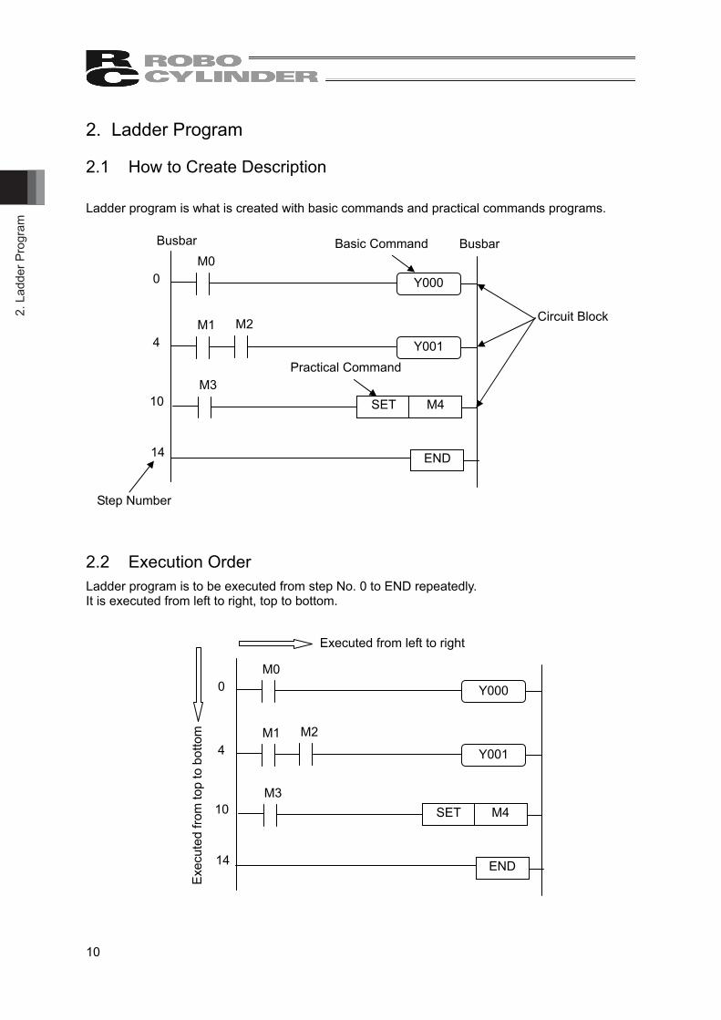
Ladder program is what is created with basic commands and practical commands programs. 2.2 Execution Order Ladder program is to be executed from step No. 0 to END repeatedly. It is executed from left to right, top to bottom.
Y000 0 M0
Y001 4 M1 M2
10 M3
SET M4
END 14
Circuit Block
Busbar Busbar
Step Number
Basic Command
Practical Command
Y000 0 M0
Y001 4 M1 M2
10 M3
SET M4
END 14
Executed from left to right
Exe
cute
d fro
m to
p to
bot
tom
2. Ladder Program
11
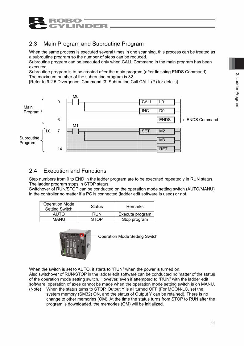
2.3 Main Program and Subroutine Program When the same process is executed several times in one scanning, this process can be treated as a subroutine program so the number of steps can be reduced. Subroutine program can be executed only when CALL Command in the main program has been executed. Subroutine program is to be created after the main program (after finishing ENDS Command) The maximum number of the subroutine program is 32. [Refer to 9.2.5 Divergence Command [3] Subroutine Call CALL (P) for details]
M0 0
CALL L0
INC D0
6 ENDS ←ENDS Command
M1 L0 7
SET M2
M3
14 RET
2.4 Execution and Functions Step numbers from 0 to END in the ladder program are to be executed repeatedly in RUN status. The ladder program stops in STOP status. Switchover of RUN/STOP can be conducted on the operation mode setting switch (AUTO/MANU) in the controller no matter if a PC is connected (ladder edit software is used) or not.
Operation Mode Setting Switch Status Remarks
AUTO RUN Execute program MANU STOP Stop program
When the switch is set to AUTO, it starts to “RUN” when the power is turned on. Also switchover of RUN/STOP in the ladder edit software can be conducted no matter of the status of the operation mode setting switch. However, even if attempted to “RUN” with the ladder edit software, operation of axes cannot be made when the operation mode setting switch is on MANU. (Note) When the status turns to STOP, Output Y is all turned OFF (For MCON-LC, set the
system memory (SM32) ON, and the status of Output Y can be retained). There is no change to other memories (OM). At the time the status turns from STOP to RUN after the program is downloaded, the memories (OM) will be initialized.
Main Program
Subroutine Program
Operation Mode Setting Switch
2. L
adde
r Pro
gram
12
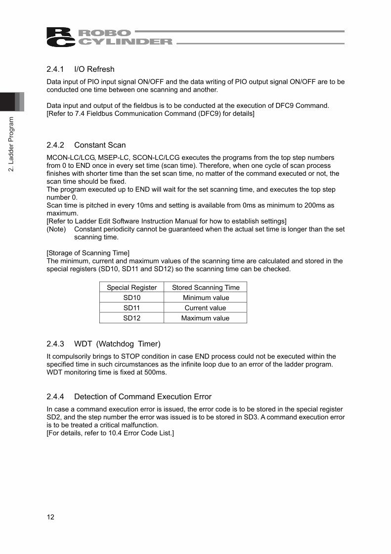
2.4.1 I/O Refresh Data input of PIO input signal ON/OFF and the data writing of PIO output signal ON/OFF are to be conducted one time between one scanning and another. Data input and output of the fieldbus is to be conducted at the execution of DFC9 Command. [Refer to 7.4 Fieldbus Communication Command (DFC9) for details]
2.4.2 Constant Scan MCON-LC/LCG, MSEP-LC, SCON-LC/LCG executes the programs from the top step numbers from 0 to END once in every set time (scan time). Therefore, when one cycle of scan process finishes with shorter time than the set scan time, no matter of the command executed or not, the scan time should be fixed. The program executed up to END will wait for the set scanning time, and executes the top step number 0. Scan time is pitched in every 10ms and setting is available from 0ms as minimum to 200ms as maximum. [Refer to Ladder Edit Software Instruction Manual for how to establish settings] (Note) Constant periodicity cannot be guaranteed when the actual set time is longer than the set
scanning time. [Storage of Scanning Time] The minimum, current and maximum values of the scanning time are calculated and stored in the special registers (SD10, SD11 and SD12) so the scanning time can be checked.
Special Register Stored Scanning Time SD10 Minimum value SD11 Current value SD12 Maximum value
2.4.3 WDT (Watchdog Timer) It compulsorily brings to STOP condition in case END process could not be executed within the specified time in such circumstances as the infinite loop due to an error of the ladder program. WDT monitoring time is fixed at 500ms. 2.4.4 Detection of Command Execution Error In case a command execution error is issued, the error code is to be stored in the special register SD2, and the step number the error was issued is to be stored in SD3. A command execution error is to be treated a critical malfunction. [For details, refer to 10.4 Error Code List.]

2. Ladder Program
13
2.5 Available Numbers The numbers available to use are the decimal (DEC) and hexadecimal (HEX) numbers as shown below. A real number with floating or fixed-point cannot be used.
Type Description Example Range Decimal Describe with number
from 0 to 9 (with no symbol added)
1234 Word data : -32768 to 32767 2 Word data : -2147483648 to 2147483647
Hexadecimal Describe with number from 0 to 9, A, B, C, D, E, and F with H on top
H1234 Word data : H0 to HFFFF 2 Word data : H0 to HFFFFFFFF
2.6 Total Number of Steps The total number of the steps in MSEP-LC, SCON-LC/LCG is more than 4096 steps. The total number of the steps in MCON-LC/LCG is more than 12288 steps.

3. In
put a
nd O
utpu
t (PI
O) A
ssig
nmen
t
14
3. Input and Output (PIO) Assignment 3.1 MSEP-LC, MCON-LC/LCG Input and output (PIO) can be prepared at 32 points of input and 32 points of output at maximum in total of Slot 1 and Slot 2. Shown below is the assignment on PIO connectors. (Note) It cannot control an actuator directly with Input and Output (PIO) Signal like MSEP-C and
MCON-C Controller does. It is necessary to make a ladder program so the actuator can be controlled with Input and Output (PIO) Signal. [Refer to 10.5 Basic Positioning Sequence (Example)]
(Note) Slot 2 can also be used as the fieldbus. Fieldbus is applicable to DeviceNet, CC-Link, PROFIBUS-DP, CompoNet, EtherNet/IP, PROFINET-IO and EtherCAT.
Slot 1
Connector pin No. Front of MSEP-LC, MCON-LC/LCG Slot 2 Connector pin No.
A (Upper Row)
B (Lower Row)
B (Lower Row)
A (Upper Row)
1 1 20 20 2 2 19 19 3 3 18 18 4 4 17 17 5 5 16 16 6 6 15 15 7 7 14 14 8 8 13 13 9 9 12 12
10 10 11 11 11 11 10 10 12 12 9 9 13 13 8 8 14 14 7 7 15 15 6 6 16 16 5 5 17 17 4 4 18 18 3 3 19 19 2 2 20 20
1 1
3. Input and Output (PIO
) Assignment
15
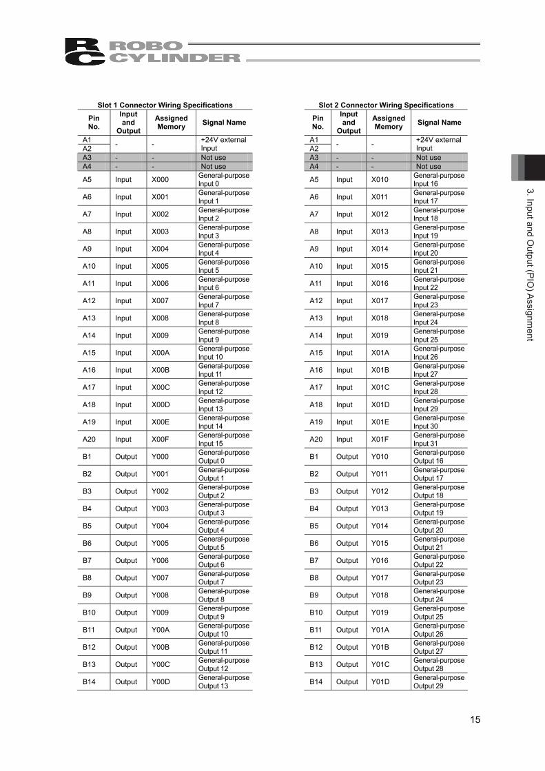
Slot 1 Connector Wiring Specifications Slot 2 Connector Wiring Specifications
Pin No.
Input and
Output Assigned Memory Signal Name
Pin No.
Input and
OutputAssigned Memory Signal Name
A1 A1 A2 - - +24V external
Input A2 - - +24V external Input
A3 - - Not use A3 - - Not use A4 - - Not use A4 - - Not use
A5 Input X000 General-purpose Input 0
A5 Input X010 General-purpose Input 16
A6 Input X001 General-purpose Input 1
A6 Input X011 General-purpose Input 17
A7 Input X002 General-purpose Input 2
A7 Input X012 General-purpose Input 18
A8 Input X003 General-purpose Input 3
A8 Input X013 General-purpose Input 19
A9 Input X004 General-purpose Input 4
A9 Input X014 General-purpose Input 20
A10 Input X005 General-purpose Input 5
A10 Input X015 General-purpose Input 21
A11 Input X006 General-purpose Input 6
A11 Input X016 General-purpose Input 22
A12 Input X007 General-purpose Input 7
A12 Input X017 General-purpose Input 23
A13 Input X008 General-purpose Input 8
A13 Input X018 General-purpose Input 24
A14 Input X009 General-purpose Input 9
A14 Input X019 General-purpose Input 25
A15 Input X00A General-purpose Input 10
A15 Input X01A General-purpose Input 26
A16 Input X00B General-purpose Input 11
A16 Input X01B General-purpose Input 27
A17 Input X00C General-purpose Input 12
A17 Input X01C General-purpose Input 28
A18 Input X00D General-purpose Input 13
A18 Input X01D General-purpose Input 29
A19 Input X00E General-purpose Input 14
A19 Input X01E General-purpose Input 30
A20 Input X00F General-purpose Input 15
A20 Input X01F General-purpose Input 31
B1 Output Y000 General-purpose Output 0
B1 Output Y010 General-purpose Output 16
B2 Output Y001 General-purpose Output 1
B2 Output Y011 General-purpose Output 17
B3 Output Y002 General-purpose Output 2
B3 Output Y012 General-purpose Output 18
B4 Output Y003 General-purpose Output 3
B4 Output Y013 General-purpose Output 19
B5 Output Y004 General-purpose Output 4
B5 Output Y014 General-purpose Output 20
B6 Output Y005 General-purpose Output 5
B6 Output Y015 General-purpose Output 21
B7 Output Y006 General-purpose Output 6
B7 Output Y016 General-purpose Output 22
B8 Output Y007 General-purpose Output 7
B8 Output Y017 General-purpose Output 23
B9 Output Y008 General-purpose Output 8
B9 Output Y018 General-purpose Output 24
B10 Output Y009 General-purpose Output 9
B10 Output Y019 General-purpose Output 25
B11 Output Y00A General-purpose Output 10
B11 Output Y01A General-purpose Output 26
B12 Output Y00B General-purpose Output 11
B12 Output Y01B General-purpose Output 27
B13 Output Y00C General-purpose Output 12
B13 Output Y01C General-purpose Output 28
B14 Output Y00D General-purpose Output 13
B14 Output Y01D General-purpose Output 29

3. In
put a
nd O
utpu
t (PI
O) A
ssig
nmen
t
16
Pin No.
Input and
Output Assigned Memory Signal Name
Pin No.
Input and
OutputAssigned Memory Signal Name
B15 Output Y00E General-purpose Output 14
B15 Output Y01E General-purpose Output 30
B16 Output Y00F General-purpose Output 15
B16 Output Y01F General-purpose Output 31
B17 - - Not use B17 - - Not use B18 - - Not use B18 - - Not use B19 B19 B20 - - 0V external
Input B20 - - 0V external Input

3. Input and Output (PIO
) Assignment
17
3.2 SCON-LC/LCG (Note) PIO and fieldbus cannot be used at the same time.
3.2.1 PIO The input and output of PIO is 16 points for input and 16 points for output. Shown below is the assignment of PIO connector.
(Note) It is not available to control actuator directly with input and output (PIO) signals like SCON-CB Controller. It is necessary to establish the ladder program in order to control the actuator with the input and output (PIO) signals.
Connector Wiring Specifications
Pin No. Input and
OutputAssigned Memory Signal Name
A1 - - +24V external Input A2 A3 - - Not use A4 - - Not use A5 Input X000 General-purpose Input 0A6 Input X001 General-purpose Input 1A7 Input X002 General-purpose Input 2A8 Input X003 General-purpose Input 3A9 Input X004 General-purpose Input 4
A10 Input X005 General-purpose Input 5A11 Input X006 General-purpose Input 6A12 Input X007 General-purpose Input 7A13 Input X008 General-purpose Input 8A14 Input X009 General-purpose Input 9A15 Input X00A General-purpose Input 10A16 Input X00B General-purpose Input 11A17 Input X00C General-purpose Input 12A18 Input X00D General-purpose Input 13A19 Input X00E General-purpose Input 14A20 Input X00F General-purpose Input 15B1 Output Y000 General-purpose Output 0B2 Output Y001 General-purpose Output 1B3 Output Y002 General-purpose Output 2B4 Output Y003 General-purpose Output 3B5 Output Y004 General-purpose Output 4B6 Output Y005 General-purpose Output 5B7 Output Y006 General-purpose Output 6B8 Output Y007 General-purpose Output 7B9 Output Y008 General-purpose Output 8
B10 Output Y009 General-purpose Output 9B11 Output Y00A General-purpose Output 10B12 Output Y00B General-purpose Output 11B13 Output Y00C General-purpose Output 12B14 Output Y00D General-purpose Output 13B15 Output Y00E General-purpose Output 14B16 Output Y00F General-purpose Output 15B17 - - Not use B18 - - Not use B19 - - 0V external Input B20
A1
A20
B1
B20

3. In
put a
nd O
utpu
t (PI
O) A
ssig
nmen
t
18
3.2.2 Fieldbus Input and output of the fieldbus is 64 points for input and 64 points for output. The fieldbus domains are assigned as shown below. (Note) Fieldbus is applicable to ether of DeviceNet, CC-Link, PROFIBUS-DP, CompoNet,
EtherNet/IP, PROFINET-IO, EtherCAT and MECHATROLINK-I/II. CC-Link (Remote Device Station 1 Station 1 Time)
RX0 Not use RY0 Not use RX1 Not use RY1 Not use RWr0 Y000 to Y00F RWw0 X000 to X00F RWr1 Y010 to Y01F RWw1 X010 to X01F RWr2 Y020 to Y02F RWw2 X020 to X02F RWr3 Y030 to Y03F RWw3 X030 to X03F
Other Networks (Input 8 Bytes / Output 8 Bytes)
Input 0 word Y000 to Y00F Output 0 word X000 to X00F Input 1 word Y010 to Y01F Output 1 word X010 to X01F Input 2 word Y020 to Y02F Output 2 word X020 to X02F Input 3 word Y030 to Y03F Output 3 word X030 to X03F
4. Mem
ory List
19
4. Memory List
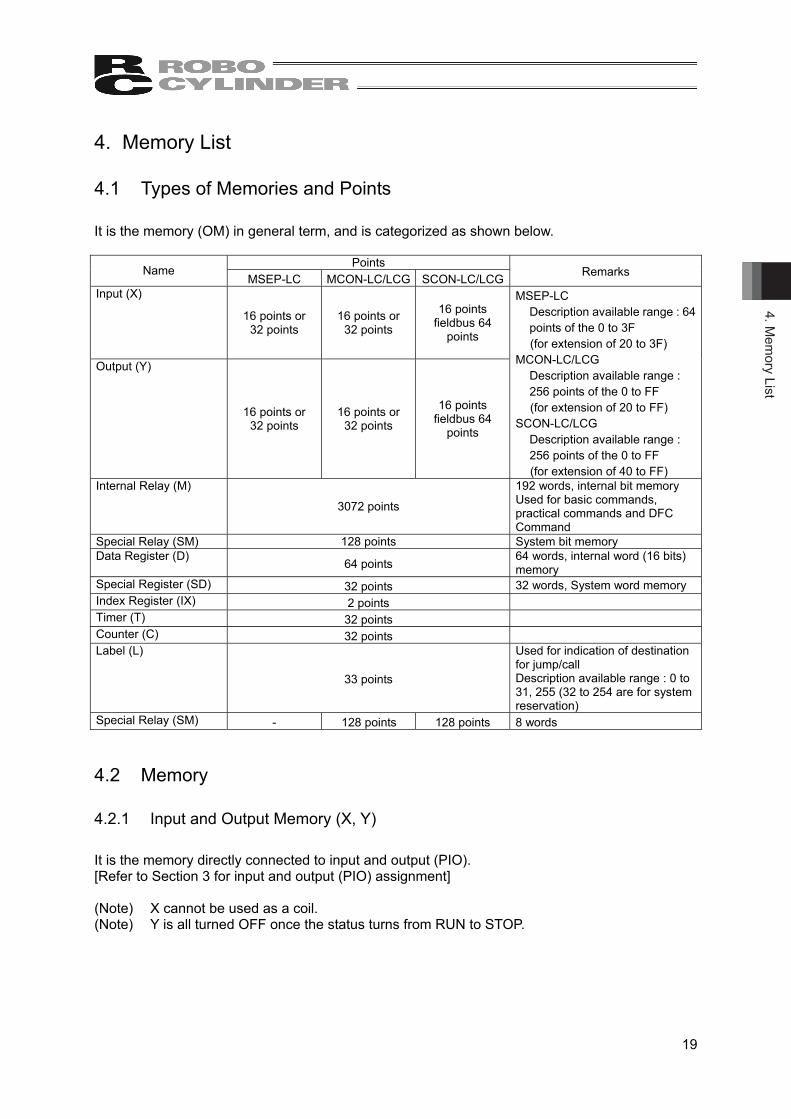
4.1 Types of Memories and Points It is the memory (OM) in general term, and is categorized as shown below.
Points Name
MSEP-LC MCON-LC/LCG SCON-LC/LCG Remarks
Input (X)
16 points or 32 points
16 points or 32 points
16 points fieldbus 64
points
Output (Y)
16 points or 32 points
16 points or 32 points
16 points fieldbus 64
points
MSEP-LC Description available range : 64 points of the 0 to 3F (for extension of 20 to 3F)
MCON-LC/LCG Description available range : 256 points of the 0 to FF (for extension of 20 to FF)
SCON-LC/LCG Description available range : 256 points of the 0 to FF (for extension of 40 to FF)
Internal Relay (M)
3072 points
192 words, internal bit memory Used for basic commands, practical commands and DFC Command
Special Relay (SM) 128 points System bit memory Data Register (D)
64 points 64 words, internal word (16 bits) memory
Special Register (SD) 32 points 32 words, System word memory Index Register (IX) 2 points Timer (T) 32 points Counter (C) 32 points Label (L)
33 points
Used for indication of destination for jump/call Description available range : 0 to 31, 255 (32 to 254 are for system reservation)
Special Relay (SM) - 128 points 128 points 8 words
4.2 Memory 4.2.1 Input and Output Memory (X, Y) It is the memory directly connected to input and output (PIO). [Refer to Section 3 for input and output (PIO) assignment] (Note) X cannot be used as a coil. (Note) Y is all turned OFF once the status turns from RUN to STOP.

4. M
emor
y Li
st
20
4.2.2 Internal Relay (M) It is the bit memory to be used for basic commands, practical commands and DFC Command. • Conduct the description shown in the table below when dealing with several bits of bit memory.
Indication Method Example Bit Memory + “ : ” + “Number of Bits”(Note) Indicate a multiple number
of 4 such as M0 or M4 for the bit memory.
M0 : 4 It indicates to use 4 bits from the bit memory M0 to M3.
• Conduct the description shown in the table below when the bit memory with words (16 bits).
Indication Method Example Bit Memory + “W” (Note) Indicate a multiple number of
16 such as M0 or M16 for the bit memory.
M0W 16 bit memories from M0 to M15 are to be
dealt.
• Conduct the description shown in the table below when the bit memory with long words (32
bits). Indication Method Example
Bit Memory + “L” (Note) Indicate a multiple number of
16 such as M0 or M16 for the bit memory.
M0L 32 bit memories from M0 to M31 are to be
dealt.
4. Mem
ory List
21
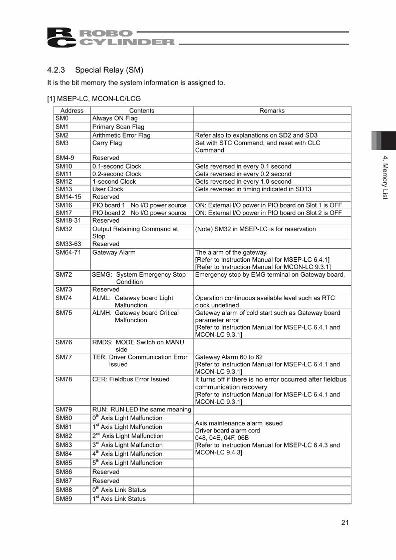
4.2.3 Special Relay (SM) It is the bit memory the system information is assigned to. [1] MSEP-LC, MCON-LC/LCG
Address Contents Remarks SM0 Always ON Flag
SM1 Primary Scan Flag
SM2 Arithmetic Error Flag Refer also to explanations on SD2 and SD3 SM3 Carry Flag Set with STC Command, and reset with CLC
Command SM4-9 Reserved
SM10 0.1-second Clock Gets reversed in every 0.1 second SM11 0.2-second Clock Gets reversed in every 0.2 second SM12 1-second Clock Gets reversed in every 1.0 second SM13 User Clock Gets reversed in timing indicated in SD13 SM14-15 Reserved
SM16 PIO board 1 No I/O power source ON: External I/O power in PIO board on Slot 1 is OFF SM17 PIO board 2 No I/O power source ON: External I/O power in PIO board on Slot 2 is OFF SM18-31 Reserved
SM32 Output Retaining Command at Stop
(Note) SM32 in MSEP-LC is for reservation
SM33-63 Reserved
SM64-71 Gateway Alarm The alarm of the gateway. [Refer to Instruction Manual for MSEP-LC 6.4.1] [Refer to Instruction Manual for MCON-LC 9.3.1]
SM72 SEMG: System Emergency Stop Condition
Emergency stop by EMG terminal on Gateway board.
SM73 Reserved
SM74 ALML: Gateway board Light Malfunction
Operation continuous available level such as RTC clock undefined
SM75 ALMH: Gateway board Critical Malfunction
Gateway alarm of cold start such as Gateway board parameter error [Refer to Instruction Manual for MSEP-LC 6.4.1 and MCON-LC 9.3.1]
SM76 RMDS: MODE Switch on MANU side
SM77 TER: Driver Communication Error Issued
Gateway Alarm 60 to 62 [Refer to Instruction Manual for MSEP-LC 6.4.1 and MCON-LC 9.3.1]
SM78 CER: Fieldbus Error Issued It turns off if there is no error occurred after fieldbus communication recovery [Refer to Instruction Manual for MSEP-LC 6.4.1 and MCON-LC 9.3.1]
SM79 RUN: RUN LED the same meaning
SM80 0th Axis Light Malfunction SM81 1st Axis Light Malfunction SM82 2nd Axis Light Malfunction SM83 3rd Axis Light Malfunction SM84 4th Axis Light Malfunction SM85 5th Axis Light Malfunction
Axis maintenance alarm issued Driver board alarm cord 048, 04E, 04F, 06B [Refer to Instruction Manual for MSEP-LC 6.4.3 and MCON-LC 9.4.3]
SM86 Reserved
SM87 Reserved
SM88 0th Axis Link Status
SM89 1st Axis Link Status

4. M
emor
y Li
st
22
Address Contents Remarks SM90 2nd Axis Link Status
SM91 3rd Axis Link Status
SM92 4th Axis Link Status
SM93 5th Axis Link Status
SM94 Reserved
SM95 Reserved
[2] SCON-LC/LCG
Address Contents Remarks SM0 Always ON Flag SM1 Primary Scan Flag SM2 Arithmetic Error Flag Refer also to explanations on SD2 and SD3 SM3 Carry Flag SM4-9 Reserved SM10 0.1-second Clock Gets reversed in every 0.1 second SM11 0.2-second Clock Gets reversed in every 0.2 second SM12 1-second Clock Gets reversed in every 1.0 second SM13 User Clock Gets reversed in timing indicated in SD13 SM16 Reserved SM32 Output Retaining Command at
Stop
SM33-77 Reserved SM78 Fieldbus link error occurred SM79-127 Reserved
4. Mem
ory List
23
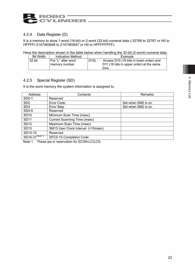
4.2.4 Data Register (D) It is a memory to store 1-word (16-bit) or 2-word (32-bit) numeral data (-32768 to 32767 or H0 to HFFFF/-2147483648 to 2147483647 or H0 to HFFFFFFFF). Have the description shown in the table below when handling the 32-bit (2-word) numeral data.
Bit Width Indication Method Example 32 bit Put “L” after word
memory number D10L · · · Access D10 (16 bits in lower-order) and
D11 (16 bits in upper order) at the same time.
4.2.5 Special Register (SD) It is the word memory the system information is assigned to.
Address Contents Remarks SD0-1 Reserved
SD2 Error Code Set when SM2 is on. SD3 Error Step Set when SM2 is on. SD4-9 Reserved
SD10 Minimum Scan Time (msec)
SD11 Current Scanning Time (msec)
SD12 Maximum Scan Time (msec)
SD13 SM13 User Clock Interval (×10msec)
SD14-15 Reserved
SD16-31(Note 1) DFC0-15 Completion Code
Note 1 These are in reservation for SCON-LC/LCG.

4. M
emor
y Li
st
24
4.2.6 Index Register (IX) Indirect indication (index modification) of the memory is available by using the index register (IX). Index register is in 16 bits. There are two types, IX0 and IX1. Index modification can be conducted on X, Y, M, T, C, SM, D, SD and L.

4. Mem
ory List
25
4.2.7 Timer (T) The timer is a count up timer. Calculation starts once the timer coil turns ON. When the current value gets the same as the set value, the timer contact turns ON. The current value turns to zero when the timer coil turns OFF, and the contact turns OFF at the same time. The maximum settable value is 32767 (327670ms).
[Timer Circuit Example]
M0 10ms
T0
T0 coil turns ON when M0 turns ON, and T0 contact turns ON in 10ms
Setting Unit 10ms unit Treatment Switching ON/OFF of the timer coil, update of current value and switching
ON/OFF of the timer contact are conducted when OUT T (timer) Command is executed. Update of timer current value and switching ON/OFF of the contact are not conducted in END process. Current value adds the value of the scan time calculated in END Command when OUT T (timer) Command is executed. i.e. the timer is calculated in scan time value. Current value would also not be updated in case the timer coil is OFF when OUT T (timer) Command is executed.
[Notes]
Number Contents 1 Several timers at the same timing cannot be made in 1 scanning.
If multiple timers in the same timing are made, update of the current value for the same timing would be held at several places, thus the calculation would not be carried out properly.
2 Execution of OUT T (timer) Command cannot be made jumped by JMP Command while the timer coil is ON. If jumped, timer contact would not turn ON/OFF.
3 If the timer is set zero, the setting value is treated as infinite. 4 When using two timers, have the ON/OFF circuit as shown in the diagram below.
[Example for using two timer circuits or more]
T0 10ms
T1
Calculation made for 10ms after T0 is turned on
T1 10ms
T0
Calculation made for 10ms when T1 is OFF
T0
M0
Repeated to turn ON/OFF in every 10ms

4. M
emor
y Li
st
26
4.2.8 Counter (C) The counter is a count up counter. The contact turns ON when the counter value gets the same as the set value. The counter is a memory to count the number of times to raise the input condition. The maximum settable value is 32767.
[Counter Circuit Example]
M0 10
C0
Treatment Switching ON/OFF of the timer coil, update of current value (Counter Value+1) and switching ON/OFF of the timer contact are conducted when OUT C (count) Command is executed.
Counting Up Updating of the current value is held only when the input condition rises (OFF → ON). When the input condition is OFF, it would not count on “ON → ON” and “ON → OFF”.
Counter Reset The current value of the counter will not be cleared (reset) even when the counter coil turns OFF. The current value of the counter can be cleared (reset) and contact be turned OFF in RST Command. The counter value gets cleared and contact turned OFF when RST C Command is executed.
[Counter Reset Circuit Example]
M1
RST C0
4.2.9 Label (L) The label indicates the destination to jump with the jump command. Also, it is used to indicate the top of the subroutine program in the subroutine command (CALL Command). 33 points, L0 to L31 and L255, can be used. (Note) L0 indicates the initializing dedicated routine if L0 is not indicated in Jump Command or
Subroutine Command. Also L255 indicate the program END.

4. Mem
ory List
27
4.2.10 Special Relay (SM) It is a memory that retains the values just before the power was turned off. • Conduct the description shown in the table below when dealing with several bits of bit memory.
Indication Method Example Bit Memory + “ : ” + “Number of Bits”(Note) Indicate a multiple number
of 4 such as M0 or M4 for the bit memory.
LM0 : 4 It indicates to use 4 bits from the bit memory LM0 to LM3.
• Conduct the description shown in the table below when the bit memory with words (16 bits).
Indication Method Example Bit Memory + “W” (Note) Indicate a multiple number of
16 such as M0 or M16 for the bit memory.
LM0W 16 bit memories from M0 to M15 are to be
dealt.
• Conduct the description shown in the table below when the bit memory with long words (32
bits). Indication Method Example
Bit Memory + “L” (Note) Indicate a multiple number of
16 such as M0 or M16 for the bit memory.
LM0L 32 bit memories from M0 to M31 are to be
dealt.

5. C
omm
and
Con
stru
ctio
n
28
5. Command Construction The command is constructed with command part, source data, destination data and number of transfer.
[Example for Add Command]
[Example for Block Transfer Command]
(1) Command Part
This shows the function of command. (2) Source Data
It indicates the memory (OM) that the data used in arithmetic is stored. Or, it establishes the constant used in arithmetic.
(3) Destination Data
It indicates the memory (OM) that the result of the arithmetic is stored. It is necessary to store arithmetic data in the destination data in advance to the execution of a command in such a case as a command shown below that the result of S + D is stored in D.
[Example for Add Command]
(4) Number of Transfer
It establishes the number of transfer in such a case as a command to use several memories (OM) such as block transfer command.
Source Data
MCPY S n D
Number of Transfer Command Part
Destination Data
+ S D
Command Part Destination Data Source Data
+ S D
Source Data Command Part Destination Data
5. Com
mand C
onstruction
29
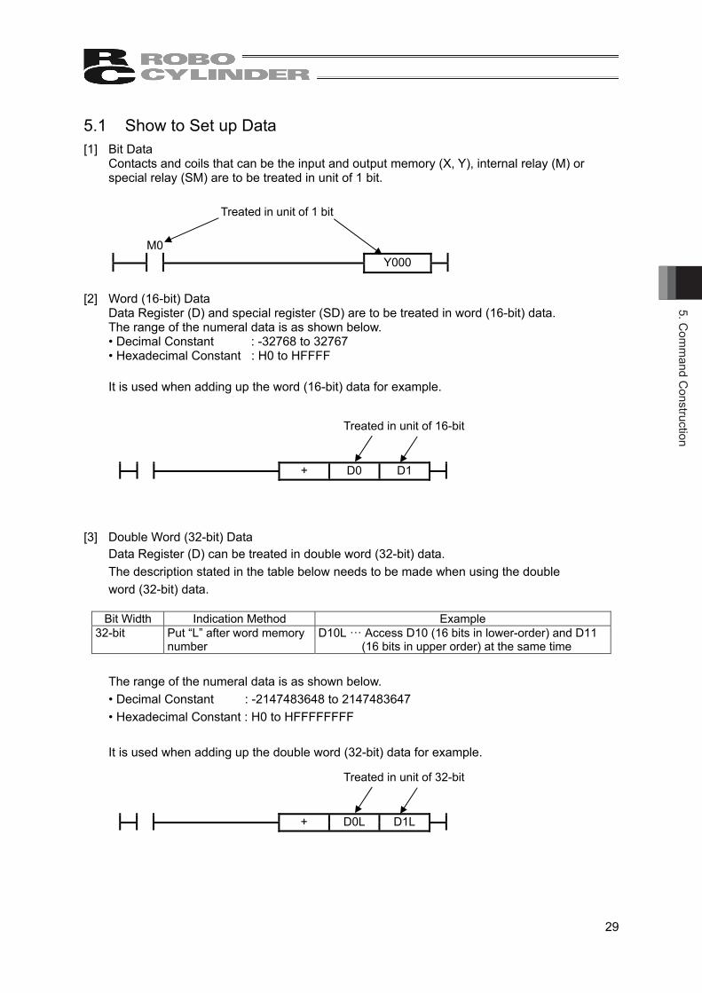
5.1 Show to Set up Data [1] Bit Data
Contacts and coils that can be the input and output memory (X, Y), internal relay (M) or special relay (SM) are to be treated in unit of 1 bit.
M0
Y000
[2] Word (16-bit) Data
Data Register (D) and special register (SD) are to be treated in word (16-bit) data. The range of the numeral data is as shown below. • Decimal Constant : -32768 to 32767 • Hexadecimal Constant : H0 to HFFFF
It is used when adding up the word (16-bit) data for example.
+ D0 D1
[3] Double Word (32-bit) Data
Data Register (D) can be treated in double word (32-bit) data. The description stated in the table below needs to be made when using the double word (32-bit) data.
Bit Width Indication Method Example
32-bit Put “L” after word memory number
D10L ··· Access D10 (16 bits in lower-order) and D11 (16 bits in upper order) at the same time
The range of the numeral data is as shown below. • Decimal Constant : -2147483648 to 2147483647 • Hexadecimal Constant : H0 to HFFFFFFFF
It is used when adding up the double word (32-bit) data for example.
+ D0L D1L
Treated in unit of 1 bit
Treated in unit of 16-bit
Treated in unit of 32-bit
5. C
omm
and
Con
stru
ctio
n
30
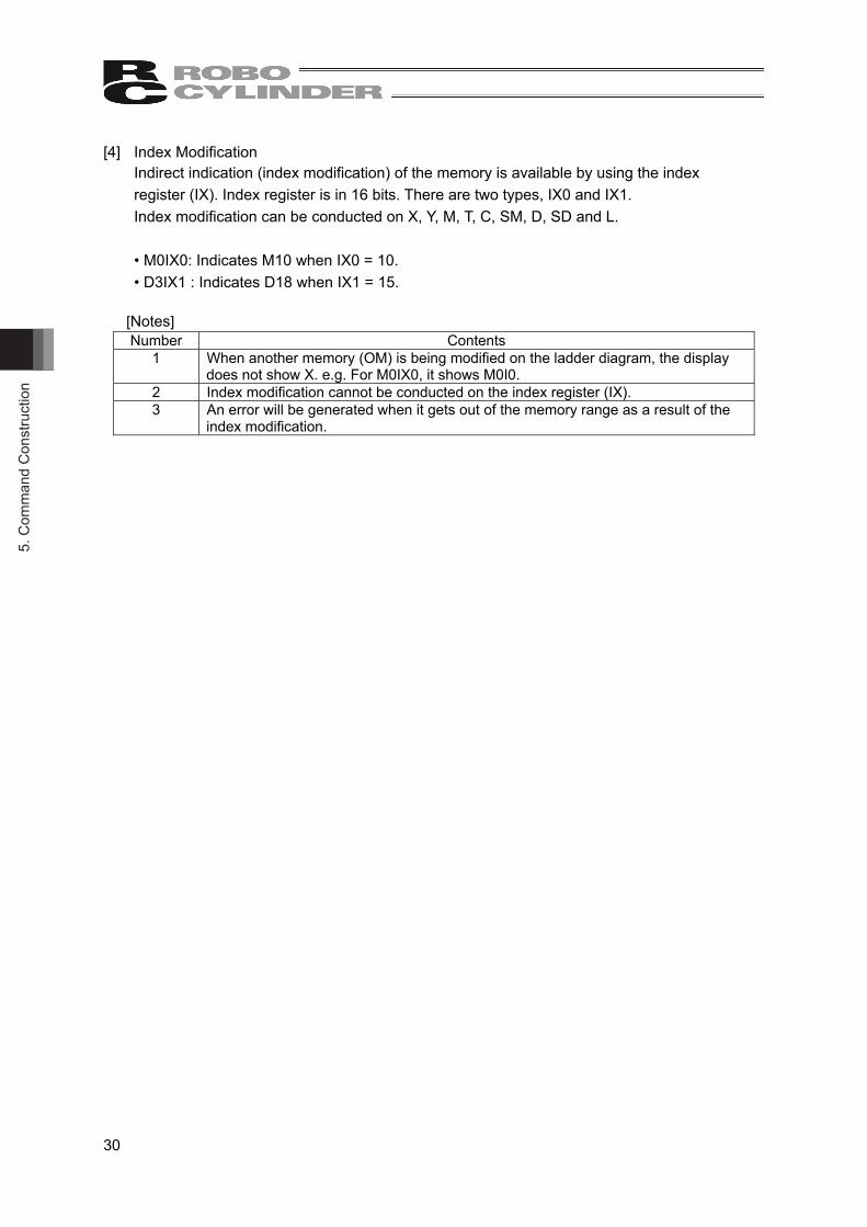
[4] Index Modification Indirect indication (index modification) of the memory is available by using the index register (IX). Index register is in 16 bits. There are two types, IX0 and IX1. Index modification can be conducted on X, Y, M, T, C, SM, D, SD and L.
• M0IX0: Indicates M10 when IX0 = 10. • D3IX1 : Indicates D18 when IX1 = 15.
[Notes] Number Contents
1 When another memory (OM) is being modified on the ladder diagram, the display does not show X. e.g. For M0IX0, it shows M0I0.
2 Index modification cannot be conducted on the index register (IX). 3 An error will be generated when it gets out of the memory range as a result of the
index modification.

5. Com
mand C
onstruction
31
5.2 Condition of Command Execution There are four types of conditions as follows of the command execution. • Commands always executed • Commands that are executed when input conditions rise (OFF → ON) • Commands that are executed when input conditions fall (ON → OFF) • Commands that are executed only when input conditions are ON [1] Commands always executed
Such commands as LD command (symbol: ) and LDN command (symbol: ) can always be executed. Check the explanation of each command.
[2] Commands that are executed when input conditions rise (OFF → ON)
The commands with “P” at the end are those executed when the input conditions rise (OFF → ON).
A command such as LDP command (symbol: ) fall under this group. Check the explanation of each command.
[3] Commands that are executed when input conditions fall (ON → OFF)
The commands with “NP” at the end are those executed when the input conditions fall (ON → OFF). A command such as LDNP command (symbol: ) fall under this group. Check the explanation of each command.
[4] Commands that are executed only when input conditions are ON
A command such as MOV command (symbol: ) is the one executed only when the input condition is ON. Check the explanation of each command.
MOV S D

5. C
omm
and
Con
stru
ctio
n
32
5.3 Number of Steps The number of steps for the basic commands and practical commands is the number that 1 step is added to the source data, destination data and number of transfer. e.g. + Command is 3 steps.
MCPY Command is 4 steps.
Check in the command list.
Command Part Source Data
Destination Data
MCPY S n D
Number of Transfer
3 + 1 = 4 steps
+ S D
2 + 1 = 3 steps Source Data Destination Data Command Part
6. How
to View C
omm
ands
33
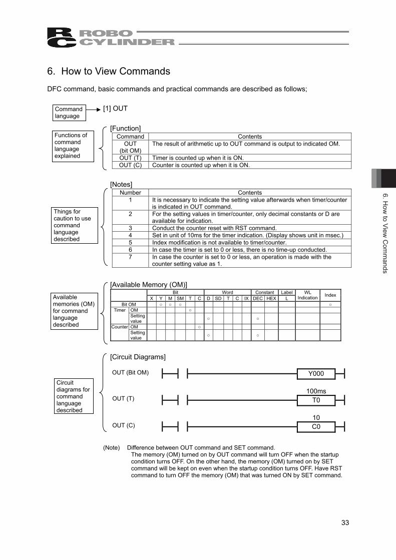
6. How to View Commands DFC command, basic commands and practical commands are described as follows;
[1] OUT
[Function] Command Contents
OUT (bit OM)
The result of arithmetic up to OUT command is output to indicated OM.
OUT (T) Timer is counted up when it is ON. OUT (C) Counter is counted up when it is ON.
[Notes] Number Contents
1 It is necessary to indicate the setting value afterwards when timer/counter is indicated in OUT command.
2 For the setting values in timer/counter, only decimal constants or D are available for indication.
3 Conduct the counter reset with RST command. 4 Set in unit of 10ms for the timer indication. (Display shows unit in msec.) 5 Index modification is not available to timer/counter. 6 In case the timer is set to 0 or less, there is no time-up conducted. 7 In case the counter is set to 0 or less, an operation is made with the
counter setting value as 1.
[Available Memory (OM)]
Bit Word Constant Label X Y M SM T C D SD T C IX DEC HEX L
WL Indication Index
Bit OM ○ ○ ○ ○ OM ○ Timer Setting value ○ ○
OM ○ Counter Setting value ○ ○
[Circuit Diagrams]
Y000
100ms
T0
10
C0
(Note) Difference between OUT command and SET command.
The memory (OM) turned on by OUT command will turn OFF when the startup condition turns OFF. On the other hand, the memory (OM) turned on by SET command will be kept on even when the startup condition turns OFF. Have RST command to turn OFF the memory (OM) that was turned ON by SET command.
Command language
Functions of command language explained
Things for caution to use command language described
Available memories (OM) for command language described
Circuit diagrams for command language described
OUT (Bit OM)
OUT (T)
OUT (C)

7. D
edic
ated
Com
man
d (D
FC C
omm
and)
34
7. Dedicated Command (DFC Command) MCON-LC/LCG, MSEP-LC controller uses the dedicated commands as DFC (Dynamic Function Call) Command to control axes as well as the basic commands such as LD Command and practical commands such as + Command. There are three types prepared as DFC command • Axis Control Command • Command Transfer Command between Axis and Driver • Fieldbus Communication Command (Note) There is no dedicated command (DFC Command) in SCON-LC/LCG. 7.1 Registration of DFC It is necessary to set up the definition for DFC command in the ladder edit tool software. However, it is not necessary to change the setting when no change is made to the names from those stated in the table below. Select in order of Support → DFC setting → DFC registration in the menu of the ladder edit tool software to establish the settings. Register the names of commands to the numbers shown in the table below. Register the registration name stated in the list and screen. In this instruction manual, explanation is provided with those registration names (examples) hereafter.
No. Definition Contents Command Name (Example) 0 Control Command of Axis No. 0 AX0IOE 1 Control Command of Axis No. 1 AX1IOE 2 Control Command of Axis No. 2 AX2IOE 3 Control Command of Axis No. 3 AX3IOE 4 Control Command of Axis No. 4 AX4IOE 5 Control Command of Axis No. 5 AX5IOE 6 Future expansion
7 Future expansion
8 Command Transfer Command between Axis and Driver CMDIOE
9 Fieldbus Communication Command MWXCHG 10 Positioning Command to Axis No. 0 AX0MVP 11 Positioning Command to Axis No. 1 AX1MVP 12 Positioning Command to Axis No. 2 AX2MVP 13 Positioning Command to Axis No. 3 AX3MVP 14 Positioning Command to Axis No. 4 AX4MVP 15 Positioning Command to Axis No. 5 AX5MVP

7. Dedicated C
omm
and (DFC
Com
mand)
35
DFC Registration Screen (other than MCON-LC/LCG)
DFC Registration Screen (MCON-LC/LCG)
NWXCHG

7. D
edic
ated
Com
man
d (D
FC C
omm
and)
36
7.2 Axis Control Command (DFC0-5) It is a command to assign the input and output domains of the axis to be used to the internal relay (M) domain, and update the internal buffer to be used when communicating with a driver board at execution.
[Function] Command Contents DFC0 to 5 Regarding the axis indicated with function name, with the address indicated in S1 as
the top, the input and output domains to the axes are assigned to the internal relay (M) domains with the IO patterns indicated in S2. It is a command to update the internal buffer to be used when communicating with a driver board at execution.
[Notes]
Number Contents 1 Have this always executed to avoid any unexpected cutoff of axis command or
response. 2 It is necessary to reboot MSEP-LC at the change of S1 and S2. 3 Do not attempt to set the number of axes in Gateway Parameter Setting Tool. 4 When selecting the internal relay (M) in S1, set a number multiple of 16 in the bit
numbers such as M384. 5 Duplication check in the domains secured in S1 and S2 for each axis is not
conducted. Pay attention not to make duplication when establishing the memory assignment settings.
6 Make the IO Patterns for two axes (S2) in the same slot. In case they are not the same, the smaller one will be prioritized.
[Available Memory (OM)]
Bit Word Constant Label X Y M SM T C D SD T C IX DEC HEX L
WL Indication Index
S1 ○ ○ S2 ○ ○
[Available S2 Values]
S2 Values
IO Pattern Name
MSEP Guideline for Assignment (Refer to 10.4 for assignment of MCON-LC/LCG) Remarks
0 Simple Direct 4 words from S1: Axis status input, Next 4 words: Axis control output
1 Positioner 1 Same as above
2 Positioner 2 2 words from S1: Axis status input, Next 2 words: Axis control output
3 Positioner 3 1 word from S1: Axis status input, Next 1 word: Axis control output
4 Direct Indication
8 words from S1: Axis status input, Next 8 words: Axis control output
[Circuit diagrams] SM0
DFC
DFC Function Name S1 S2
• S1 : Top address of internal relay (M) • S2 : IO Pattern

7. Dedicated C
omm
and (DFC
Com
mand)
37
Shown below is an example of execution when the condition is set as follows; • DFC registration names : 0 axis AX0IOE • S1 : Top address of internal relay (M) M384 • S2 : IO Pattern 0 Simple Direct [Example of Execution] SM0
DFC
DFC AX0IOE M384 0
When executed as shown in the diagram above, the input and output assignment of Axis 0 is as shown below as the simple direct type.
Current Value L 399 398 397 396 395 394 393 392 391 390 389 388 387 386 385 384
Current Value H 415 414 413 412 411 410 409 408 407 406 405 404 403 402 401 400
PM 431 430 429 428 427 426 425 424 423 422 421 420 419 418 417 416 Condition Word 447 446 445 444 443 442 441 440 439 438 437 436 435 434 433 432
EM
GS
CR
DY
Z1
Z2
-
-
-
ME
ND
ALM
L
-
PS
FL
SV
ALM
MO
VE
HE
ND
PE
ND
Target Value L 463 462 461 460 459 458 457 456 455 454 453 452 451 450 449 448
Target Value H 479 478 477 476 475 474 473 472 471 470 469 468 467 466 465 464
PC 495 494 493 492 491 490 489 488 487 486 485 484 483 482 481 480 Control Word 511 510 509 508 507 506 505 504 503 502 501 500 499 498 497 496
BK
RL
-
-
-
-
-
-
JOG
+
JOG
-
-
JIS
L
SO
N
RE
S
STP
HO
ME
CS
TR
[Refer to 10.1 Axis Control Command (DFC0 to 5) Address Map for the address maps for IO patterns.]
7. D
edic
ated
Com
man
d (D
FC C
omm
and)
38
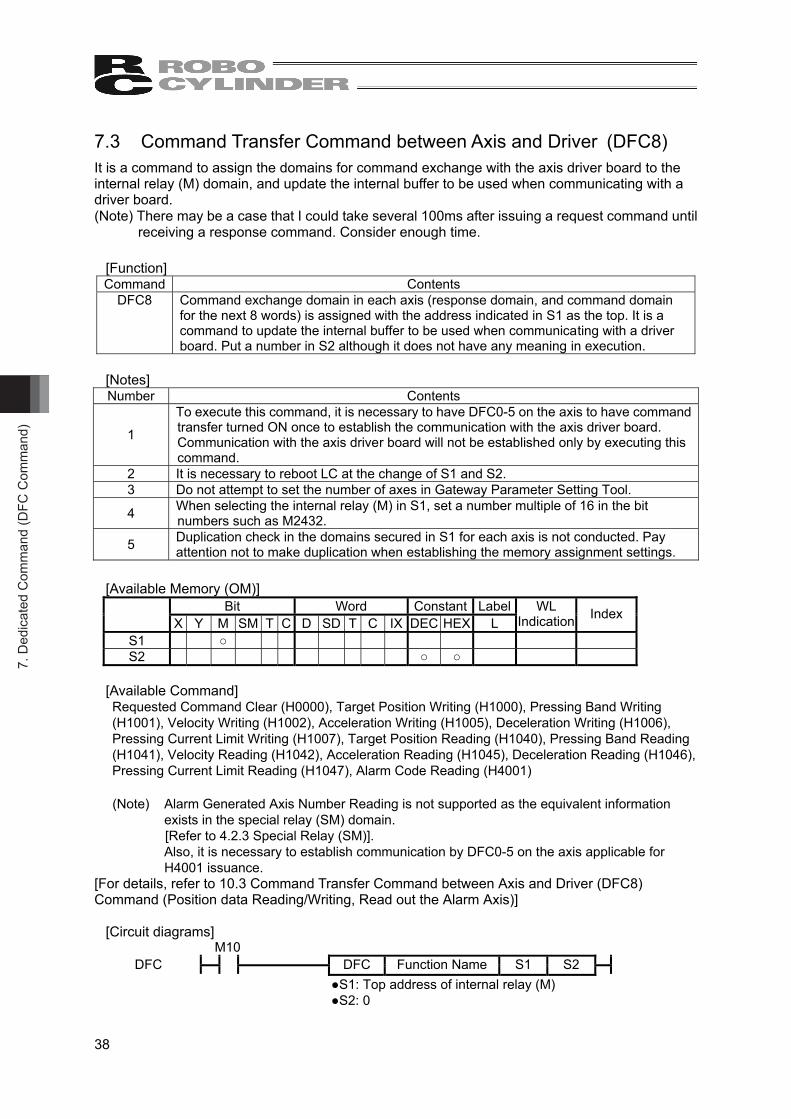
7.3 Command Transfer Command between Axis and Driver (DFC8) It is a command to assign the domains for command exchange with the axis driver board to the internal relay (M) domain, and update the internal buffer to be used when communicating with a driver board. (Note) There may be a case that I could take several 100ms after issuing a request command until
receiving a response command. Consider enough time.
[Function] Command Contents
DFC8 Command exchange domain in each axis (response domain, and command domain for the next 8 words) is assigned with the address indicated in S1 as the top. It is a command to update the internal buffer to be used when communicating with a driver board. Put a number in S2 although it does not have any meaning in execution.
[Notes] Number Contents
1
To execute this command, it is necessary to have DFC0-5 on the axis to have command transfer turned ON once to establish the communication with the axis driver board. Communication with the axis driver board will not be established only by executing this command.
2 It is necessary to reboot LC at the change of S1 and S2. 3 Do not attempt to set the number of axes in Gateway Parameter Setting Tool.
4 When selecting the internal relay (M) in S1, set a number multiple of 16 in the bit numbers such as M2432.
5 Duplication check in the domains secured in S1 for each axis is not conducted. Pay attention not to make duplication when establishing the memory assignment settings.
[Available Memory (OM)]
Bit Word Constant Label X Y M SM T C D SD T C IX DEC HEX L
WL Indication Index
S1 ○ S2 ○ ○
[Available Command] Requested Command Clear (H0000), Target Position Writing (H1000), Pressing Band Writing (H1001), Velocity Writing (H1002), Acceleration Writing (H1005), Deceleration Writing (H1006), Pressing Current Limit Writing (H1007), Target Position Reading (H1040), Pressing Band Reading (H1041), Velocity Reading (H1042), Acceleration Reading (H1045), Deceleration Reading (H1046), Pressing Current Limit Reading (H1047), Alarm Code Reading (H4001)
(Note) Alarm Generated Axis Number Reading is not supported as the equivalent information exists in the special relay (SM) domain. [Refer to 4.2.3 Special Relay (SM)]. Also, it is necessary to establish communication by DFC0-5 on the axis applicable for H4001 issuance.
[For details, refer to 10.3 Command Transfer Command between Axis and Driver (DFC8) Command (Position data Reading/Writing, Read out the Alarm Axis)]
[Circuit diagrams]
M10
DFC
DFC Function Name S1 S2
●S1: Top address of internal relay (M) ●S2: 0

7. Dedicated C
omm
and (DFC
Com
mand)
39
Shown below is an example for when assigning the command exchange domain from M2432. [Example of Execution]
M10
DFC
DFC CMDIOE M2432 0
The command domain will be assigned as shown in the table below.
Response command M2432W Request command M2560W Response position No. (Note 1) M2448W Request position No. (Note 1) (Note 2) M2576W Response data 0 M2464W Request data 0 (Note 2) M2592W Response data 1 M2480W Request data 1 (Note 2) M2608W Response axis No. M2496W Request axis No. (Note 2) M2624W Reserved M2512W Reserved M2640W Reserved M2528W Reserved M2656W Reserved M2544W Reserved M2672W
Note1 There is no response position No. or request position No. to alarm code reading (H4001). Note2 There is no response position No. or requested data 0, requested data 1, or request axis
No. to response command clear (H0000).

7. D
edic
ated
Com
man
d (D
FC C
omm
and)
40
7.4 Fieldbus Communication Command (DFC9) It is a command to assign the fieldbus domains to the internal relay (M) domain, and update the fieldbus data buffer. It is a command to receive data such as a start command from the host and to send an alarm data to the host. It is not a command to receive data to control an actuator like Fieldbus Type of other controllers. For instance, when receiving a command of the position from the host with this command, it is necessary to make a ladder program so the received position data can be executed in the axis control command (DFC0-5).
[Function] Command Contents
DFC9 The four words from the address indicated in S1 are assigned to the fieldbus input domain, and the next four words to the output domain. It is a command to update the fieldbus data buffer. Put a number in S2 although it does not have any meaning in execution.
[Notes] Number Contents
1 It is necessary to reboot LC at the change of S1 and S2.
2 When selecting the internal relay (M) in S1, set a number multiple of 16 in the bit numbers such as M2432.
3 Duplication check in the domains secured in S1 for each axis is not conducted. Pay attention not to make duplication when establishing the memory assignment settings.
[Available Memory (OM)] Bit Word Constant Label
X Y M SM T C D SD T C IX DEC HEX L WL
Indication Index
S1 ○ S2 ○ ○
[Circuit diagrams] SM0
DFC
DFC Function Name S1 S2
[Example of Execution] Shown below is an example for when assigning the fieldbus domain from M512.
SM0
DFC
DFC NWXCHG M512 0
The fieldbus domain will be assigned as shown in the table below.
CC-Link (Remote device station, 1 station 1 time) RX0 M512W RY0 M608W RX1 M528W RY1 M624W RWr0 M544W RWw0 M640W RWr1 M560W RWw1 M656W RWr2 M576W RWw2 M672W RWr3 M592W RWw3 M688W
Other Network (Input8 byte / output 8 byte) Input 0 word M512W Output 0 word M576W Input 1 word M528W Output 1 word M592W Input 2 word M544W Output 2 word M608W Input 3 word M560W Output 3 word M624W
7. Dedicated C
omm
and (DFC
Com
mand)
41
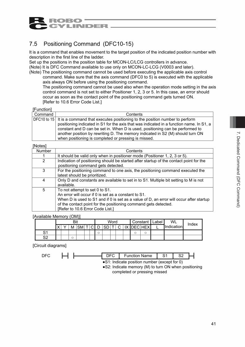
7.5 Positioning Command (DFC10-15) It is a command that enables movement to the target position of the indicated position number with description in the first line of the ladder. Set up the positions in the position table for MCON-LC/LCG controllers in advance. (Note) It is DFC Command available to use only on MCON-LC-LCG (V0003 and later). (Note) The positioning command cannot be used before executing the applicable axis control
command. Make sure that the axis command (DFC0 to 5) is executed with the applicable axis always ON before using the positioning command. The positioning command cannot be used also when the operation mode setting in the axis control command is not set to either Positioner 1, 2, 3 or 5. In this case, an error should occur as soon as the contact point of the positioning command gets turned ON. [Refer to 10.6 Error Code List.]
[Function] Command Contents DFC10 to 15 It is a command that executes positioning to the position number to perform
positioning indicated in S1 for the axis that was indicated in a function name. In S1, a constant and D can be set in. When D is used, positioning can be performed to another position by rewriting D. The memory indicated in S2 (M) should turn ON when positioning is completed or pressing is missed.
[Notes] Number Contents
1 It should be valid only when in positioner mode (Positioner 1, 2, 3 or 5). 2 Indication of positioning should be started after startup of the contact point for the
positioning command gets detected. 3 For the positioning command to one axis, the positioning command executed the
latest should be prioritized. 4 Only D and constants are available to set in to S1. Multiple bit setting to M is not
available. 5 To not attempt to set 0 to S1.
An error will occur if 0 is set as a constant to S1. When D is used to S1 and if 0 is set as a value of D, an error will occur after startup of the contact point for the positioning command gets detected. [Refer to 10.6 Error Code List.]
[Available Memory (OM)] Bit Word Constant Label
X Y M SM T C D SD T C IX DEC HEX L WL
Indication Index
S1 ○ ○ ○ S2 ○
[Circuit diagrams]
DFC
DFC Function Name S1 S2
●S1: Indicate position number (except for 0) ●S2: Indicate memory (M) to turn ON when positioning
completed or pressing missed

7. D
edic
ated
Com
man
d (D
FC C
omm
and)
42
[Process of Positioning Command] Following processes should be performed in response to the status of the contact point for the positioning command.
Status of Contact Point for Positioning Command
Detail of Basic Operation
ON • At startup (OFF to ON), indication for positioning to the indicated position number (S1) should be made.
• The indicated bit (S2) gets turned ON when the positioning operation to the indicated position number (S1) gets finished (positioning completed or pressing missed), and the indicated bit (S2) gets turned OFF when the operation is not finished.
OFF • The indicated bit (S2) gets turned OFF.
With using the value of S1 when the contact point of the position command turns ON, movement to the indicated position number starts. Even if the value in S1 gets changed (value changed using D) while the contact point is kept ON, it would not cause an error at execution as the value in S1 would not be checked after the operation has started. S2 turns ON after the positioning is completed.
[Movement of Multiple Axes] By making the S2 memory the contact of the next position command (DFC 10 to 15) or the condition to have the contact turned ON, several axes can be set to move one after another.
[Continuous Position Movement of One Axis] By making the S2 memory condition to have the contact of the next position command (DFC 10 to 15) turned ON, one axis can be moved continuously. Not that using as a contact point itself would cause the operation become as described below.
When a positioning command (hereafter called as Command 1) is executed, positioning is finished, and then another positioning command (hereafter called as Command 2) to move to another position number is executed on the same axis, S2 fo Command 1 should turn OFF. If S2 of Command 1 is used as the contact point of Command 2, S2 of Command 1 should turn OFF straight after Command 2 gets executed, and Command 2 itself also gets turned OFF. At this time, even though the positioning operation to the position number indicated in Command 2 will be executed, S2 of Command 2 would not turn ON when the positioning operation is finished.

8. Basic Com
mand
43
8.Basic Command 27 types of basic commands such as LD command are available to use in this controller. (Timer output and counter output are counted as OUT command) 8.1 Basic Command List
Classification Command Symbol Processing Step Number Page
LD S ─┤ ├─ normal open contact 2 41 LDN S ─┤/├─ normal close contact 2 41 OR S └┤ ├┘ normal open contact 2 41 ORN S └┤/├┘ normal close contact 2 41 AND S ─┤ ├─ normal open contact 2 41 ANDN S ─┤/├─ normal close contact 2 41 LDP S ─┤ ↑ ├─ Startup Trigger 2 42 LDNP S ─┤ ↓ ├─ Startup Trigger 2 42 ORP S └┤ ↑ ├┘ Startup Trigger 2 42 ORNP S └┤ ↓ ├┘ Startup Trigger 2 42 ANDP S ─┤ ↑ ├─ Startup Trigger 2 42
Contact Command
ANDNP S ─┤ ↓ ├─ Startup Trigger 2 42 OR-BLK OR block process 1 43 AND-BLK - AND block process 1 43 M-PUSH - Memory writing 1 44 M-READ - Memory reading 1 44
Connect Command(Note 1)
M-POP - Memory reading 1 44 OUT D ─( )─ Coil output 2 45
OUT T setting
value ─( )─ Timer output 3 45
OUT C setting
value ─( )─ Counter output 3 45
SET D ─[ ]─ OM set 2 46 RST D ─[ ]─ OM reset 2 46 PLS D ─[ ]─ Pulse output 2 47 PLSN D ─[ ]─ Pulse OFF output 2 47
Output Command
SFT D ─[ ]─ Bit shift 2 48 END(Note 2) ─[ ]─ Program end 1 49 Termination
Command ENDS(Note 3) ─[ ]─ Main routine end 1 49 Note 1 It does not appear on ladder diagram. Note 2 It is inserted in the end of the program. Note 3 It is used to make a subroutine description between ENDS and END.

8. B
asic
Com
man
d
44
8.2 Explanation of the Command 8.2.1 Contact Command [1] LD, LDN, AND, ANDN, OR, ORN
LD, AND and OR are activated when the contact is on, and LDN, ANDN and ORN are activated when the contact is OFF.
[Function] Command Contents LD, LDN The contents of bits are directly or reversely stored in arithmetic result.
AND, ANDN
Series connection command. The arithmetic result as of now and direct or reversed logical conjunction are defined as the arithmetic result.
OR, ORN Parallel connection command. The arithmetic result as of now and direct or reversed logical disjunction are defined as the arithmetic result.
[Available Memory (OM)] Bit Word Constant Label
X Y M SM T C D SD T C IX DEC HEX L WL
Indication Index
○ ○ ○ ○ ○ ○ ○
[Circuit diagrams]
LD
LDN
/
AND
ANDN
/
OR
ORP
/
(Note) LD, LDN, AND, ANDN, OR and ORN commands are not displayed as commands in the
ladder program. They are automatically classified by the position to use the contact signs.
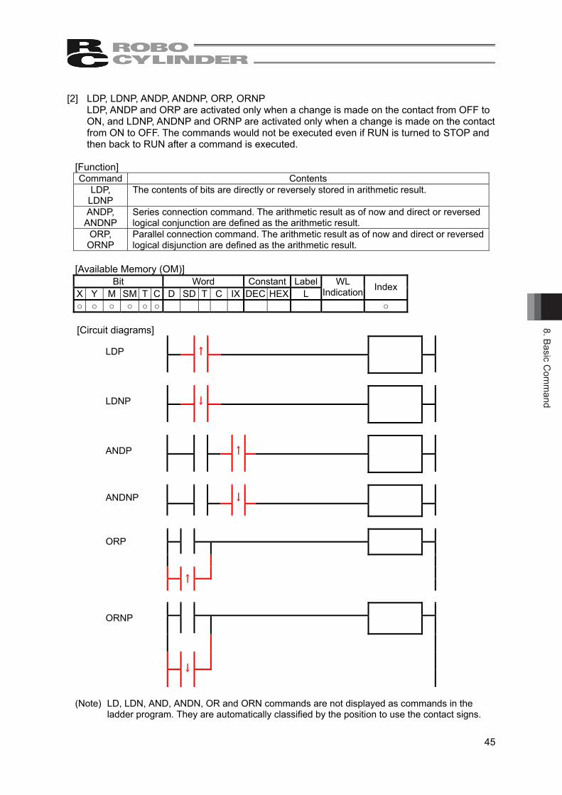
8. Basic Com
mand
45
[2] LDP, LDNP, ANDP, ANDNP, ORP, ORNP LDP, ANDP and ORP are activated only when a change is made on the contact from OFF to ON, and LDNP, ANDNP and ORNP are activated only when a change is made on the contact from ON to OFF. The commands would not be executed even if RUN is turned to STOP and then back to RUN after a command is executed.
[Function] Command Contents
LDP, LDNP
The contents of bits are directly or reversely stored in arithmetic result.
ANDP, ANDNP
Series connection command. The arithmetic result as of now and direct or reversed logical conjunction are defined as the arithmetic result.
ORP, ORNP
Parallel connection command. The arithmetic result as of now and direct or reversed logical disjunction are defined as the arithmetic result.
[Available Memory (OM)] Bit Word Constant Label
X Y M SM T C D SD T C IX DEC HEX L WL
Indication Index
○ ○ ○ ○ ○ ○ ○
[Circuit diagrams]
LDP
↑
LDNP
↓
ANDP
↑
ANDNP
↓
ORP
↑
ORNP
↓
(Note) LD, LDN, AND, ANDN, OR and ORN commands are not displayed as commands in the
ladder program. They are automatically classified by the position to use the contact signs.
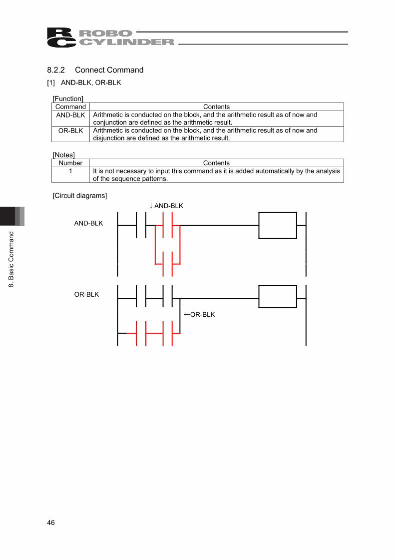
8. B
asic
Com
man
d
46
8.2.2 Connect Command [1] AND-BLK, OR-BLK
[Function] Command Contents AND-BLK Arithmetic is conducted on the block, and the arithmetic result as of now and
conjunction are defined as the arithmetic result. OR-BLK Arithmetic is conducted on the block, and the arithmetic result as of now and
disjunction are defined as the arithmetic result.
[Notes] Number Contents
1 It is not necessary to input this command as it is added automatically by the analysis of the sequence patterns.
[Circuit diagrams] ↓AND-BLK
AND-BLK
OR-BLK
←OR-BLK
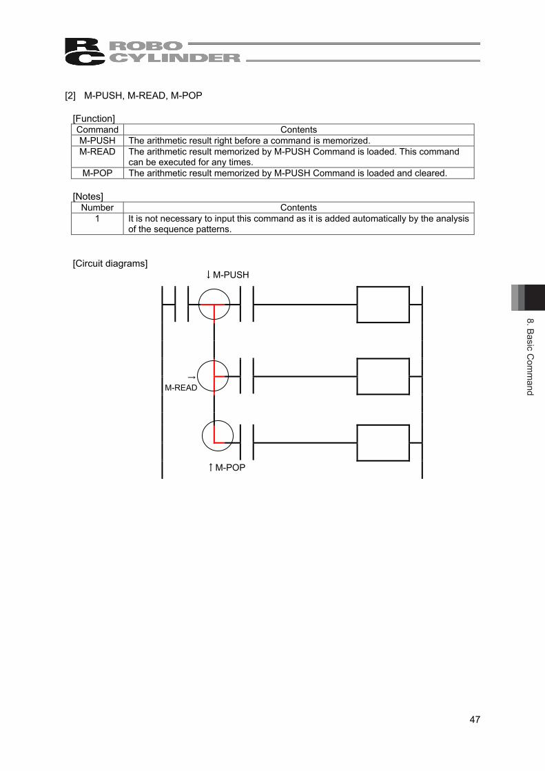
8. Basic Com
mand
47
[2] M-PUSH, M-READ, M-POP
[Function] Command Contents M-PUSH The arithmetic result right before a command is memorized. M-READ The arithmetic result memorized by M-PUSH Command is loaded. This command
can be executed for any times. M-POP The arithmetic result memorized by M-PUSH Command is loaded and cleared.
[Notes] Number Contents
1 It is not necessary to input this command as it is added automatically by the analysis of the sequence patterns.
[Circuit diagrams] ↓M-PUSH
↑M-POP
→ M-READ
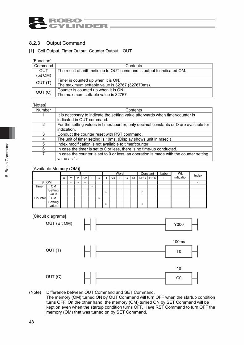
8. B
asic
Com
man
d
48
8.2.3 Output Command [1] Coil Output, Timer Output, Counter Output OUT
[Function] Command Contents
OUT (bit OM)
The result of arithmetic up to OUT command is output to indicated OM.
OUT (T) Timer is counted up when it is ON. The maximum settable value is 32767 (327670ms).
OUT (C) Counter is counted up when it is ON. The maximum settable value is 32767.
[Notes] Number Contents
1 It is necessary to indicate the setting value afterwards when timer/counter is indicated in OUT command.
2 For the setting values in timer/counter, only decimal constants or D are available for indication.
3 Conduct the counter reset with RST command. 4 The unit of timer setting is 10ms. (Display shows unit in msec.) 5 Index modification is not available to timer/counter. 6 In case the timer is set to 0 or less, there is no time-up conducted. 7 In case the counter is set to 0 or less, an operation is made with the counter setting
value as 1.
[Available Memory (OM)] Bit Word Constant Label
X Y M SM T C D SD T C IX DEC HEX L WL
Indication Index
Bit OM ○ ○ ○ ○ OM ○ Timer
Setting value ○ ○
OM ○ Counter Setting value ○ ○
[Circuit diagrams]
OUT (Bit OM)
Y000
100ms
OUT (T)
T0
10
OUT (C)
C0
(Note) Difference between OUT Command and SET Command. The memory (OM) turned ON by OUT Command will turn OFF when the startup condition turns OFF. On the other hand, the memory (OM) turned ON by SET Command will be kept on even when the startup condition turns OFF. Have RST Command to turn OFF the memory (OM) that was turned on by SET Command.

8. Basic Com
mand
49
[2] OM set SET
[Function] Command Contents
SET The value in the indicated memory (OM) is turned ON and maintained. When the startup condition is OFF, the status of the memory (OM) will not change.
[Available Memory (OM)] Bit Word Constant Label
X Y M SM T C D SD T C IX DEC HEX L WL
Indication Index
D ○ ○ ○ ○
[Circuit diagrams]
SET
SET D
(Note 1) Difference between OUT command and SET command The memory (OM) turned ON by OUT command will turn OFF when the startup condition turns OFF. On the other hand, the memory (OM) turned ON by SET command will be kept on even when the startup condition turns OFF. Have RST Command to turn OFF the memory (OM) that was turned on by SET Command.
[3] OM reset RST
[Function] Command Contents
RST The value in the indicated memory (OM) is cleared. When the startup condition is OFF, the status of the memory (OM) will not change. When bit OM: turn OFF coil and contact. When word OM: set the current value to 0. When timer/counter: set the current value to 0, and turn OFF coil and contact.
[Available Memory (OM)]
Bit Word Constant Label WL Indication Index
X Y M SM T C D SD T C IX DEC HEX L D ○ ○ ○ ○ ○ ○ ○ ○ ○ ○ ○
[Circuit diagrams]
RST
RST D

8. B
asic
Com
man
d
50
[4] Pulse Output PLS, PLSN
[Function] Command Contents
PLS When the arithmetic result is OFF → ON, the indicated memory (OM) turns on for only 1 scan.
PLSN When the arithmetic result is ON → OFF, the indicated memory (OM) turns on for only 1 scan.
[Available Memory (OM)]
Bit Word Constant Label X Y M SM T C D SD T C IX DEC HEX L
WL Indication Index
D ○ ○ ○ ○
[Circuit diagrams]
PLS
PLS D
PLSN
PLSN D

8. Basic Com
mand
51
[5] Bit Shift SFT, SFTP
[Function] Command Contents
SFT When the arithmetic result is ON, the status of the bit memory (OM) is shifted to the bit in the next memory (OM) number. The status of ON/OFF the memory (OM) one step younger than the memory (OM) indicated as D is shifted to the memory (OM) indicated as D and the memory (OM) one step younger is turned OFF.
SFTP The status of the bit memory (OM) is shifted to the bit in the next memory (OM) number when the arithmetic result is switched from OFF to ON. The status of ON/OFF the memory (OM) one step younger than the memory (OM) indicated as D is shifted to the memory (OM) indicated as D and the memory (OM) one step younger is turned OFF.
[Notes]
Number Contents 1 Turn ON the top memory (OM) to shift by SET Command. 2 Set in the program from bigger memory (OM) number when using SFT and SFTP
Commands in a row.
[Available Memory (OM)] Bit Word Constant Label
X Y M SM T C D SD T C IX DEC HEX L WL
Indication Index
D ○ ○ ○ ○
[Circuit diagrams]
SFT
SFT D
SFTP
SFTP D

8. B
asic
Com
man
d
52
8.2.4 Termination Command [1] Program End END
[Function] Command Contents
END It shows the end of the program.
[Notes]
Number Contents 1 It is not necessary to input this command as it is added automatically.
[Arithmetic Error]
Error Code Contents 3 After execution of CALL (P), END command is executed before execution of RET
command. 3 After execution of FOR command, END command is executed before execution of
NEXT command.
[Circuit diagrams]
END
END
[2] Program Process End ENDS
[Function] Command Contents
ENDS It terminates the process of main routine. It is to be utilized when description of the subroutine program is to be made or process is to be diverged.
[Notes]
Number Contents 1 It is not available to add condition to this command.
[Arithmetic Error]
Error Code Contents 3 After execution of CALL (P), ENDS command is executed before execution of
RET command. 3 After execution of FOR command, ENDS command is executed before execution
of NEXT command.
[Circuit diagrams]
ENDS
ENDS
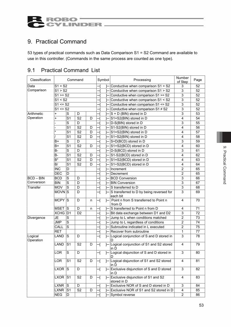
9. Practical Com
mand
53
9. Practical Command 53 types of practical commands such as Data Comparison S1 = S2 Command are available to use in this controller. (Commands in the same process are counted as one type). 9.1 Practical Command List
Classification Command Symbol Processing Number of Step Page
S1 = S2 ─[ ]─ Conductive when comparison S1 = S2 3 52 S1 > S2 ─[ ]─ Conductive when comparison S1 > S2 3 52 S1 >= S2 ─[ ]─ Conductive when comparison S1 >= S2 3 52 S1 < S2 ─[ ]─ Conductive when comparison S1 < S2 3 52 S1 <= S2 ─[ ]─ Conductive when comparison S1 <= S2 3 52
Data Comparison
S1 <> S2 ─[ ]─ Conductive when comparison S1 ≠ S2 3 52 + S D ─[ ]─ S + D (BIN) stored in D 3 53 + S1 S2 D ─[ ]─ S1+S2(BIN) stored in D 4 54 - S D ─[ ]─ D-S(BIN) stored in D 3 55 - S1 S2 D ─[ ]─ S1-S2(BIN) stored in D 4 56 * S1 S2 D ─[ ]─ S1×S2(BIN) stored in D 4 57 / S1 S2 D ─[ ]─ S1÷S2(BIN) stored in D 4 58 B+ S D ─[ ]─ S+D(BCD) stored in D 3 59 B+ S1 S2 D ─[ ]─ S1+S2(BCD) stored in D 4 60 B- S D ─[ ]─ D-S(BCD) stored in D 3 61 B- S1 S2 D ─[ ]─ S1-S2(BCD) stored in D 4 62 B* S1 S2 D ─[ ]─ S1×S2(BCD) stored in D 4 63 B/ S1 S2 D ─[ ]─ S1÷S2(BCD) stored in D 4 64 INC D ─[ ]─ Increment 2 65
Arithmetic Operation
DEC D ─[ ]─ Decrement 2 65 BCD S D ─[ ]─ BCD Conversion 3 66 BCD – BIN
Conversion BIN S D ─[ ]─ BIN Conversion 3 67 MOV S D ─[ ]─ S transferred to D 3 68 MOVN S D ─[ ]─ S transferred to D by being reversed for
each bit 3 69
MCPY S D n ─[ ]─ Point n from S transferred to Point n from D
4 70
MSET S D n ─[ ]─ S transferred to Point n from D 4 71
Transfer
XCHG D1 D2 ─[ ]─ Bit data exchange between D1 and D2 3 72 JE S ─[ ]─ Jump to L when conditions matched 2 73 JMP S ─[ ]─ Jump to L regardless of conditions 2 74 CALL S ─[ ]─ Subroutine indicated in L executed 2 75
Divergence
RET ─[ ]─ Recover from subroutine 1 77 LAND S D ─[ ]─ Logical conjunction of S and D stored in
D 3 78
LAND S1 S2 D ─[ ]─ Logical conjunction of S1 and S2 stored in D
4 79
LOR S D ─[ ]─ Logical disjunction of S and D stored in D
3 80
LOR S1 S2 D ─[ ]─ Logical disjunction of S1 and S2 stored in D
4 81
LXOR S D ─[ ]─ Exclusive disjunction of S and D stored in D
3 82
LXOR S1 S2 D ─[ ]─ Exclusive disjunction of S1 and S2 stored in D
4 83
LXNR S D ─[ ]─ Exclusive NOR of S and D stored in D 3 84 LXNR S1 S2 D ─[ ]─ Exclusive NOR of S1 and S2 stored in D 4 85
Logical Operation
NEG D ─[ ]─ Symbol reverse 2 86

9. P
ract
ical
Com
man
d
54
Classification Command Symbol Processing Number
of Step Page
ROR D n ─[ ]─ Turn n to right for n bits with carry flag excluded
3 87
RCR D n ─[ ]─ Turn n to right for n bits with carry flag included
3 89
ROL D n ─[ ]─ Turn n to left for n bits with carry flag excluded
3 90
Rotation
RCL D n ─[ ]─ Turn n to left for n bits with carry flag included
3 91
SHR D n ─[ ]─ Shift D to right for n bits 3 92 SHL D n ─[ ]─ Shift D to left for n bits 3 93 BSHR D n ─[ ]─ Shift n bits to right from D for one bit 3 94 BSHL D n ─[ ]─ Shift n bits to left from D for one bit 3 95 WSHR D n ─[ ]─ Shift Point n to right from D for one point 3 96
Shift
WSHL D n ─[ ]─ Shift Point n to left from D for one point 3 97 SUM S D ─[ ]─ Store number of ON bits of 16-bit data in
S to D 3 98
DECO S D n ─[ ]─ Decode lower n bits in S and store from 2n to D
4 99
ENCO S D n ─[ ]─ Encode 2n bits from S and store to D 4 100 BSET D n ─[ ]─ Set n bits from D 3 101 BRST D n ─[ ]─ Reset n bits from D 3 102 DDV S D n ─[ ]─ Store n digits in S to lower four bits for n
points from D 4 103
Data Processing
DCV S D n ─[ ]─ Store lower four-bit data for n points from S to D
4 104
FIFW S D ─[ ]─ Writing in FIFO table 3 105 FIFO FIFR D1 D2 ─[ ]─ Read from FIFO table 3 107 FOR S ─[ ]─ 2 108 NEXT ─[ ]─
Execution for n times between FOR and NEXT 1 109
Loop
BREAK ─[ ]─ Execution of next step to NEXT 1 110 STC ─[ ]─ Set carry flag contact 1 111 Carry Flag CLC ─[ ]─ Reset carry flag contact 1 111
DFC Command DFC fcn S1 S2 ─[ ]─ Call out DFC Command 4 34
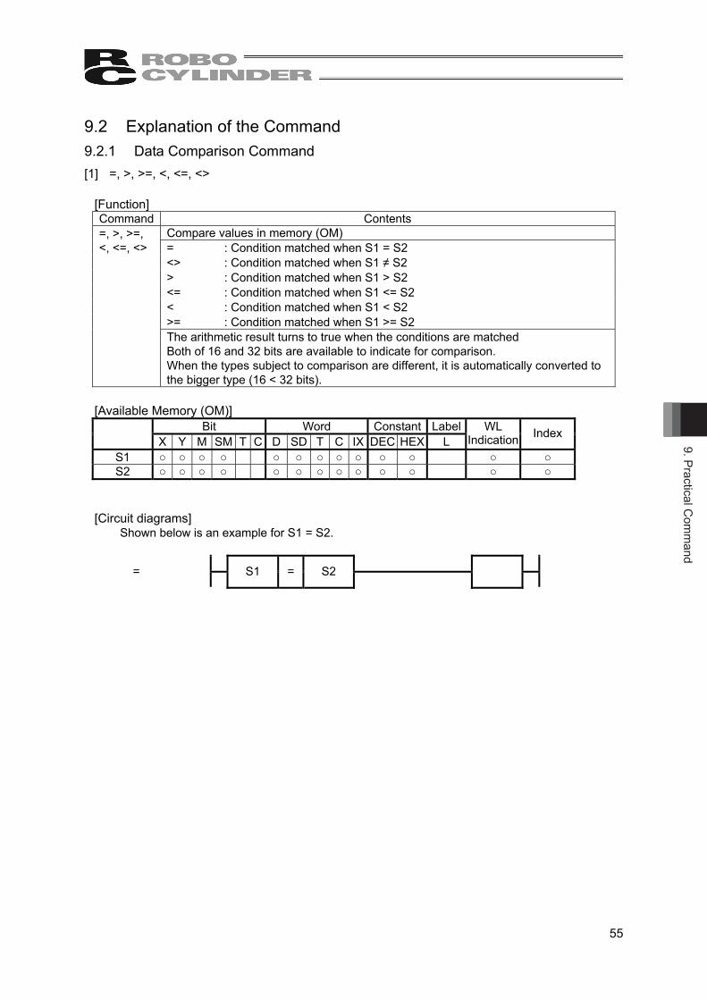
9. Practical Com
mand
55
9.2 Explanation of the Command 9.2.1 Data Comparison Command [1] =, >, >=, <, <=, <>
[Function] Command Contents
Compare values in memory (OM) = : Condition matched when S1 = S2 <> : Condition matched when S1 ≠ S2 > : Condition matched when S1 > S2 <= : Condition matched when S1 <= S2 < : Condition matched when S1 < S2 >= : Condition matched when S1 >= S2
=, >, >=, <, <=, <>
The arithmetic result turns to true when the conditions are matched Both of 16 and 32 bits are available to indicate for comparison. When the types subject to comparison are different, it is automatically converted to the bigger type (16 < 32 bits).
[Available Memory (OM)]
Bit Word Constant Label X Y M SM T C D SD T C IX DEC HEX L
WL Indication Index
S1 ○ ○ ○ ○ ○ ○ ○ ○ ○ ○ ○ ○ ○ S2 ○ ○ ○ ○ ○ ○ ○ ○ ○ ○ ○ ○ ○
[Circuit diagrams] Shown below is an example for S1 = S2.
=
S1 = S2

9. P
ract
ical
Com
man
d
56
9.2.2 Arithmetic Operation Command [1] Binary Addition +(P)(2)
[Function] Command Contents
+(2) BIN data indicated in S is added to BIN data indicated in D (D + S is executed), and the adding up result is stored in the memory (OM) indicated in D. Numbers from -32768 to 32767 (BIN 16 bit) can be indicated in S and D. Positive/negative of data is judged in the highest bit (b15). ꞏ ꞏ ꞏ ꞏ 0: Positive, 1: Negative The carry flag will not turn ON at the underflow of the 0th bit. The carry flag will not turn ON at the overflow of the 15th bit.
+P(2) +(2) is executed when a change is made to the arithmetic result from OFF to ON.
[Available Memory (OM)] Bit Word Constant Label
X Y M SM T C D SD T C IX DEC HEX L WL
Indication Index
S ○ ○ ○ ○ ○ ○ ○ ○ ○ ○ ○ ○ ○ D ○ ○ ○ ○ ○ ○ ○ ○ ○ ○
[Circuit diagrams]
+(2)
+ S D
+P(2)
+P S D
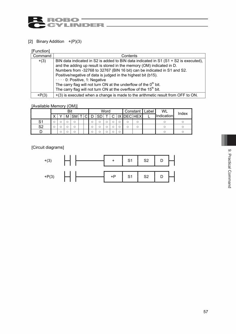
9. Practical Com
mand
57
[2] Binary Addition +(P)(3)
[Function] Command Contents
+(3) BIN data indicated in S2 is added to BIN data indicated in S1 (S1 + S2 is executed), and the adding up result is stored in the memory (OM) indicated in D. Numbers from -32768 to 32767 (BIN 16 bit) can be indicated in S1 and S2. Positive/negative of data is judged in the highest bit (b15). ꞏ ꞏ ꞏ ꞏ 0: Positive, 1: Negative The carry flag will not turn ON at the underflow of the 0th bit. The carry flag will not turn ON at the overflow of the 15th bit.
+P(3) +(3) is executed when a change is made to the arithmetic result from OFF to ON.
[Available Memory (OM)] Bit Word Constant Label
X Y M SM T C D SD T C IX DEC HEX L WL
Indication Index
S1 ○ ○ ○ ○ ○ ○ ○ ○ ○ ○ ○ ○ ○ S2 ○ ○ ○ ○ ○ ○ ○ ○ ○ ○ ○ ○ ○ D ○ ○ ○ ○ ○ ○ ○ ○ ○ ○
[Circuit diagrams]
+(3)
+ S1 S2 D
+P(3)
+P S1 S2 D

9. P
ract
ical
Com
man
d
58
[3] Binary Subtraction -(P)(2)
[Function] Command Contents
-(2) BIN data indicated in S is subtracted from BIN data indicated in D (D - S is executed), and the subtraction result is stored in the memory (OM) indicated in D. Numbers from -32768 to 32767 (BIN 16 bit) can be indicated in S and D. Positive/negative of data is judged in the highest bit (b15). ꞏ ꞏ ꞏ ꞏ 0: Positive, 1: Negative The carry flag will not turn ON at the underflow of the 0th bit. The carry flag will not turn ON at the overflow of the 15th bit.
-P(2) -(2) is executed when a change is made to the arithmetic result from OFF to ON.
[Available Memory (OM)] Bit Word Constant Label
X Y M SM T C D SD T C IX DEC HEX L WL
Indication Index
S1 ○ ○ ○ ○ ○ ○ ○ ○ ○ ○ ○ ○ ○ D ○ ○ ○ ○ ○ ○ ○ ○ ○ ○
[Circuit diagrams]
-(2)
- S D
-P(2)
-P S D

9. Practical Com
mand
59
[4] Binary Subtraction -(P)(3)
[Function] Command Contents
-(3) BIN data indicated in S2 is subtracted from BIN data indicated in S1 (S1 - S2 is executed), and the subtraction result is stored in the memory (OM) indicated in D. Numbers from -32768 to 32767 (BIN 16 bit) can be indicated in S1 and S2. Positive/negative of data is judged in the highest bit (b15). ꞏ ꞏ ꞏ ꞏ 0: Positive, 1: Negative The carry flag will not turn ON at the underflow of the 0th bit. The carry flag will not turn ON at the overflow of the 15th bit.
-P(3) -(3) is executed when a change is made to the arithmetic result from OFF to ON.
[Available Memory (OM)] Bit Word Constant Label
X Y M SM T C D SD T C IX DEC HEX L WL
Indication Index
S1 ○ ○ ○ ○ ○ ○ ○ ○ ○ ○ ○ ○ ○ S2 ○ ○ ○ ○ ○ ○ ○ ○ ○ ○ ○ ○ ○ D ○ ○ ○ ○ ○ ○ ○ ○ ○ ○
[Circuit diagrams]
-(3)
- S1 S2 D
-P(3)
-P S1 S2 D

9. P
ract
ical
Com
man
d
60
[5] Binary Multiplication *(P)
[Function] Command Contents
* BIN data indicated in S2 is multiplied by BIN data indicated in S1 (S1 S2 is executed), and the multiplication result is stored in the memory (OM) indicated in D. If D is bit memory (OM), indication is made from low bit. Numbers from -32768 to 32767 (BIN 16 bit) can be indicated in S1 and S2. (It is treated as an integer with a symbol.)
*P * is executed when a change is made to the arithmetic result from OFF to ON.
[Notes] Number Contents
1 Make sure to indicate S in 16-bit and D in 32-bit. (Arithmetic operation of 32-bit values is not available.)
[Available Memory (OM)]
Bit Word Constant Label
X Y M SM T C D SD T C IX DEC HEX L WL
Indication (Note 1)
Index
S1 ○ ○ ○ ○ ○ ○ ○ ○ ○ ○ ○ ○ ○ S2 ○ ○ ○ ○ ○ ○ ○ ○ ○ ○ ○ ○ ○ D ○ ○ ○ ○ ○ ○ ○ ○ ○ ○
Note 1 S1 and S2 are available only for multiple bit access of the bit memory (OM). D is available only for 32-bit access of both bit and word memories (OM).
[Circuit diagrams]
*
* S1 S2 D
*P
*P S1 S2 D

9. Practical Com
mand
61
[6] Binary Division /(P)
[Function] Command Contents
/ BIN data indicated in S2 is divided by BIN data indicated in S1 (S1 / S2 is executed), and the division result is stored in the memory (OM) indicated in D. When the division result is in word memory (OM), the quotient and the remainder are stored by using 32-bit. When the division result is in bit memory (OM), only the quotient is stored by using 16-bit.
Quotient : Stored in low 16-bit Remainder : Stored in higher 32-bit (only for word memory (OM))
Numbers from -32768 to 32767 (BIN 16 bit) can be indicated in S1 and S2. (It is treated as an integer with a symbol.)
/P / is executed when a change is made to the arithmetic result from OFF to ON.
An arithmetic result gets stored as shown below. S1 S2 D D+1 D+2
7700 / 1234 → 6 296 0
Quotient Remainder
[Notes] Number Contents
1 Make sure to indicate S in 16-bit and D in 32-bit. (Arithmetic operation of 32-bit values is not available.)
[Available Memory (OM)]
Bit Word Constant Label
X Y M SM T C D SD T C IX DEC HEX L WL
Indication (Note 1)
Index
S1 ○ ○ ○ ○ ○ ○ ○ ○ ○ ○ ○ ○ ○ S2 ○ ○ ○ ○ ○ ○ ○ ○ ○ ○ ○ ○ ○ D ○ ○ ○ ○ ○ ○ ○ ○ ○ ○
Note 1 S1 and S2 are available only for multiple bit access of the bit memory (OM). D is available only for 32-bit access of both bit and word memories (OM).
[Arithmetic Error]
Error Code Contents 8 When S2 is stored in 0.
[Circuit diagrams]
/
/ S1 S2 D
/P
/P S1 S2 D

9. P
ract
ical
Com
man
d
62
[7] BCD Addition B+(P) (2)
[Function] Command Contents
B+(2) BCD data indicated in S is added to BCD data indicated in D (D + S is executed), and the adding up result is stored in the memory (OM) indicated in D. A number from 0 to 9999 (BCD 4 digits) is available to indicate for S and D. Even if the adding up result exceeds 9999, the carry flag would not turn ON, and the carry of bit would be ignored.
B+(P) (2) B+(2) is executed when a change is made to the arithmetic result from OFF to ON.
If the arithmetic result exceeds 9999 (for 16-bit) or 9999 9999 (for 32-bit), the carry of bit would be ignored.
D S D 9 9 9 9 + 0 0 0 1 → 1 0 0 0 0 Carry of bit ignored
[Available Memory (OM)]
Bit Word Constant Label X Y M SM T C D SD T C IX DEC HEX L
WL Indication Index
S ○ ○ ○ ○ ○ ○ ○ ○ ○ ○ ○ ○ ○ D ○ ○ ○ ○ ○ ○ ○ ○ ○ ○
[Arithmetic Error] Error Code Contents
7 When S and D are other than BCD, or, a value other than 0 to 9 is stored in each digit.
[Circuit diagrams]
B+(2)
B+ S D
B+P(2)
B+P S D

9. Practical Com
mand
63
[8] BCD Addition B+(P) (3)
[Function] Command Contents
B+(3) BCD data indicated in S2 is added to BCD data indicated in S1 (S1 + S2 is executed), and the adding up result is stored in the memory (OM) indicated in D. A number from 0 to 9999 (BCD 4 digits) is available to indicate for S and D. Even if the adding up result exceeds 9999, the carry flag would not turn ON, and the carry of bit would be ignored.
B+(P) (3) B+(3) is executed when a change is made to the arithmetic result from OFF to ON.
If the arithmetic result exceeds 9999 (for 16-bit) or 9999 9999 (for 32-bit), the carry of bit would be ignored
S1 S2 D 9 9 9 9 + 0 0 0 1 → 1 0 0 0 0 Carry of bit ignored
[Available Memory (OM)]
Bit Word Constant Label X Y M SM T C D SD T C IX DEC HEX L
WL Indication Index
S1 ○ ○ ○ ○ ○ ○ ○ ○ ○ ○ ○ ○ ○ S2 ○ ○ ○ ○ ○ ○ ○ ○ ○ ○ ○ ○ ○ D ○ ○ ○ ○ ○ ○ ○ ○ ○ ○
[Arithmetic Error] Error Code Contents
7 When S and D are other than BCD, or, a value other than 0 to 9 is stored in each digit.
[Circuit diagrams]
B+(3)
B+ S1 S2 D
B+P(3)
B+P S1 S2 D

9. P
ract
ical
Com
man
d
64
[9] BCD Subtraction B-(P) (2)
[Function] Command Contents
B-(2) BCD data indicated in D is subtracted from BCD data indicated in S (D - S is executed), and the subtraction result is stored in the memory (OM) indicated in D. A number from 0 to 9999 (BCD 4 digits) is available to indicate for S and D. It is necessary to have the program to conduct the positive/negative judgment of the arithmetic result.
B-(P) (2) B-(2) is executed when a change is made to the arithmetic result from OFF to ON.
When D < S, the arithmetic result is as shown below. D S D 1 0 0 0 4 - 0 0 0 7 → 9 9 9 7
[Available Memory (OM)]
Bit Word Constant Label X Y M SM T C D SD T C IX DEC HEX L
WL Indication Index
S ○ ○ ○ ○ ○ ○ ○ ○ ○ ○ ○ ○ ○ D ○ ○ ○ ○ ○ ○ ○ ○ ○ ○
[Arithmetic Error] Error Code Contents
7 When S and D are other than BCD, or, a value other than 0 to 9 is stored in each digit.
[Circuit diagrams]
B-(2)
B- S D
B-P(2)
B-P S D

9. Practical Com
mand
65
[10] BCD Subtraction B-(P) (3)
[Function] Command Contents
B-(3) BCD data indicated in S2 is subtracted from BCD data indicated in S1 (S1 – S2 is executed), and the subtraction result is stored in the memory (OM) indicated in D. A number from 0 to 9999 (BCD 4 digits) is available to indicate for S and D. t is necessary to have the program to conduct the positive/negative judgment of the arithmetic result.
B-(P) (3) B-(3) is executed when a change is made to the arithmetic result from OFF to ON.
When D < S, the arithmetic result is as shown below. S1 S2 D 1 0 0 0 4 - 0 0 0 7 → 9 9 9 7
[Available Memory (OM)]
Bit Word Constant Label X Y M SM T C D SD T C IX DEC HEX L
WL Indication Index
S1 ○ ○ ○ ○ ○ ○ ○ ○ ○ ○ ○ ○ ○ S2 ○ ○ ○ ○ ○ ○ ○ ○ ○ ○ ○ ○ ○ D ○ ○ ○ ○ ○ ○ ○ ○ ○ ○
[Arithmetic Error]
Error Code Contents 7 When S and D are other than BCD, or, a value other than 0 to 9 is stored in each
digit.
[Circuit diagrams]
B-(3)
B- S1 S2 D
B-P(3)
B-P S1 S2 D

9. P
ract
ical
Com
man
d
66
[11] BCD Multiplication B*(P)
[Function] Command Contents
B* BCD data indicated in S2 is multiplied by BCD data indicated in S1 (S1 S2 is executed), and the multiplication result is stored in the memory (OM) indicated in D. A number from 0 to 9999 (BCD 4 digits) is available to indicate for S and D.
B*P B* is executed when a change is made to the arithmetic result from OFF to ON.
[Notes] Number Contents
1 Make sure to indicate S in 16-bit and D in 32-bit. (Arithmetic operation of 32-bit values is not available.)
[Available Memory (OM)]
Bit Word Constant Label
X Y M SM T C D SD T C IX DEC HEX L WL
Indication (Note 1)
Index
S1 ○ ○ ○ ○ ○ ○ ○ ○ ○ ○ ○ ○ ○ S2 ○ ○ ○ ○ ○ ○ ○ ○ ○ ○ ○ ○ ○ D ○ ○ ○ ○ ○ ○ ○ ○ ○ ○
Note 1 S1 and S2 are available only for multiple bit access of the bit memory (OM). D is available only for 32-bit access of both bit and word memories (OM).
[Arithmetic Error] Error Code Contents
7 When S and D are other than BCD, or, a value other than 0 to 9 is stored in each digit.
[Circuit diagrams]
B*
B* S1 S2 D
B*P
B*P S1 S2 D

9. Practical Com
mand
67
[12] BCD Division B/(P)
[Function] Command Contents
B/ BCD data indicated in S2 is divided by BCD data indicated in S1 (S1 / S2 is executed), and the division result is stored in the memory (OM) indicated in D. For division result, the quotient and remainder are stored by using 32-bit.
Quotient (BCD4 digits) : Stored in low 16-bit Remainder (BCD4 digits) : Stored in higher 32-bit
When bit memory (OM) is indicated for D, the remainder of the division result will not be stored.
B/P B/ is executed when a change is made to the arithmetic result from OFF to ON.
An arithmetic result gets stored as shown below. S1 S2 D D+1 D+2
7700 / 1234 → 6 296 0
Quotient Remainder
[Notes] Number Contents
1 Make sure to indicate S in 16-bit and D in 32-bit. (Arithmetic operation of 32-bit values is not available.)
[Available Memory (OM)]
Bit Word Constant Label
X Y M SM T C D SD T C IX DEC HEX L WL
Indication (Note 1)
Index
S1 ○ ○ ○ ○ ○ ○ ○ ○ ○ ○ ○ ○ ○ S2 ○ ○ ○ ○ ○ ○ ○ ○ ○ ○ ○ ○ ○ D ○ ○ ○ ○ ○ ○ ○ ○ ○ ○
Note 1 S1 and S2 are available only for multiple bit access of the bit memory (OM). D is available only for 32-bit access of both bit and word memories (OM).
[Arithmetic Error]
Error Code Contents 7 When S and D are other than BCD, or, a value other than 0 to 9 is stored in each
digit. 8 When S2 is stored in 0.
[Circuit diagrams]
B/
B/ S1 S2 D
B/P
B/P S1 S2 D
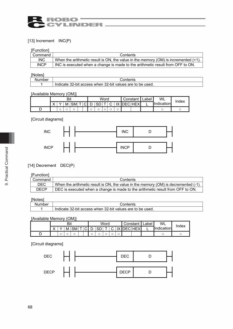
9. P
ract
ical
Com
man
d
68
[13] Increment INC(P)
[Function] Command Contents
INC When the arithmetic result is ON, the value in the memory (OM) is incremented (+1). INCP INC is executed when a change is made to the arithmetic result from OFF to ON.
[Notes]
Number Contents 1 Indicate 32-bit access when 32-bit values are to be used.
[Available Memory (OM)]
Bit Word Constant Label X Y M SM T C D SD T C IX DEC HEX L
WL Indication Index
D ○ ○ ○ ○ ○ ○ ○ ○ ○ ○
[Circuit diagrams]
INC
INC D
INCP
INCP D
[14] Decrement DEC(P)
[Function] Command Contents
DEC When the arithmetic result is ON, the value in the memory (OM) is decremented (-1). DECP DEC is executed when a change is made to the arithmetic result from OFF to ON.
[Notes]
Number Contents 1 Indicate 32-bit access when 32-bit values are to be used.
[Available Memory (OM)]
Bit Word Constant Label X Y M SM T C D SD T C IX DEC HEX L
WL Indication Index
D ○ ○ ○ ○ ○ ○ ○ ○ ○ ○
[Circuit diagrams]
DEC
DEC D
DECP
DECP D

9. Practical Com
mand
69
9.2.3 BCD / BIN Conversion Command [1] BIN→BCD Conversion BCD(P)
[Function] Command Contents
BCD BIN data in the memory (OM) indicated in S is converted into BCD, and transferred to the memory (OM) indicated in D.
BCDP BCD is executed when a change is made to the arithmetic result from OFF to ON.
[Available Memory (OM)] Bit Word Constant Label
X Y M SM T C D SD T C IX DEC HEX L WL
Indication Index
S ○ ○ ○ ○ ○ ○ ○ ○ ○ ○ ○ D ○ ○ ○ ○ ○ ○ ○ ○ ○ ○
[Arithmetic Error]
Error Code Contents 7 When a value other than BCD, 0 to 9999 (16-bit) or 0 to 9999 9999 (32-bit) is
stored in S.
[Circuit diagrams]
BCD
BCD S D
BCDP
BCDP S D

9. P
ract
ical
Com
man
d
70
[2] BCD→BIN Conversion BIN(P)
[Function] Command Contents
BIN BCD data (0 to 9999) in the memory (OM) indicated in S is converted into BIN, and transferred to the memory (OM) indicated in D.
BINP BIN is executed when a change is made to the arithmetic result from OFF to ON.
[Available Memory (OM)] Bit Word Constant Label
X Y M SM T C D SD T C IX DEC HEX L WL
Indication Index
S ○ ○ ○ ○ ○ ○ ○ ○ ○ ○ ○ D ○ ○ ○ ○ ○ ○ ○ ○ ○ ○
[Arithmetic Error]
Error Code Contents 7 When S are other than BCD, or, a value other than 0 to 9 is stored in each digit.
[Circuit diagrams]
BIN
BIN S D
BINP
BINP S D

9. Practical Com
mand
71
9.2.4 Transfer Command [1] Data Transfer MOV(P)
[Function] Command Contents
MOV When the arithmetic result is ON, the value in the memory (OM) indicated in S is transferred to the memory (OM) indicated in D.
MOVP MOV is executed when a change is made to the arithmetic result from OFF to ON.
[Notes] Number Contents
1 Indicate 32-bit access when 32-bit values are to be used.
[Available Memory (OM)] Bit Word Constant Label
X Y M SM T C D SD T C IX DEC HEX L WL
Indication Index
S ○ ○ ○ ○ ○ ○ ○ ○ ○ ○ ○ ○ ○ D ○ ○ ○ ○ ○ ○ ○ ○ ○ ○
[Circuit diagrams]
MOV
MOV S D
MOVP
MOVP S D

9. P
ract
ical
Com
man
d
72
[2] Reversed Data Transfer MOVN(P)
[Function] Command Contents
MOVN Reverse the bit data of S for each bit, and its result is transferred to D. MOVNP MOVN is executed when a change is made to the arithmetic result from OFF to ON.
[Notes]
Number Contents 1 Indicate 32-bit access when 32-bit values are to be used.
[Available Memory (OM)]
Bit Word Constant Label X Y M SM T C D SD T C IX DEC HEX L
WL Indication Index
S ○ ○ ○ ○ ○ ○ ○ ○ ○ ○ ○ ○ ○ D ○ ○ ○ ○ ○ ○ ○ ○ ○ ○
[Circuit diagrams]
MOVN
MOVN S D
MOVNP
MOVNP S D
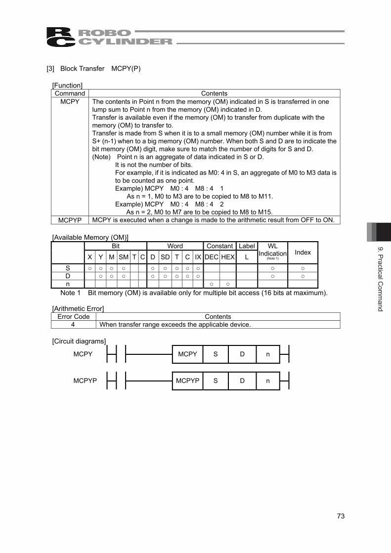
9. Practical Com
mand
73
[3] Block Transfer MCPY(P)
[Function] Command Contents
MCPY The contents in Point n from the memory (OM) indicated in S is transferred in one lump sum to Point n from the memory (OM) indicated in D. Transfer is available even if the memory (OM) to transfer from duplicate with the memory (OM) to transfer to. Transfer is made from S when it is to a small memory (OM) number while it is from S+ (n-1) when to a big memory (OM) number. When both S and D are to indicate the bit memory (OM) digit, make sure to match the number of digits for S and D. (Note) Point n is an aggregate of data indicated in S or D.
It is not the number of bits. For example, if it is indicated as M0: 4 in S, an aggregate of M0 to M3 data is to be counted as one point. Example) MCPY M0 : 4 M8 : 4 1
As n = 1, M0 to M3 are to be copied to M8 to M11. Example) MCPY M0 : 4 M8 : 4 2
As n = 2, M0 to M7 are to be copied to M8 to M15. MCPYP MCPY is executed when a change is made to the arithmetic result from OFF to ON.
[Available Memory (OM)]
Bit Word Constant Label
X Y M SM T C D SD T C IX DEC HEX L WL
Indication (Note 1)
Index
S ○ ○ ○ ○ ○ ○ ○ ○ ○ ○ ○ D ○ ○ ○ ○ ○ ○ ○ ○ ○ ○ n ○ ○
Note 1 Bit memory (OM) is available only for multiple bit access (16 bits at maximum).
[Arithmetic Error] Error Code Contents
4 When transfer range exceeds the applicable device.
[Circuit diagrams] MCPY
MCPY S D n
MCPYP
MCPYP S D n

9. P
ract
ical
Com
man
d
74
[4] Identical Data Block Transfer MSET (P)
[Function] Command Contents
MSET The identical contents in the memory (OM) indicated in S is transferred to Point n from the memory (OM) indicated in D.
MSETP MSET is executed when a change is made to the arithmetic result from OFF to ON.
[Available Memory (OM)] Bit Word Constant Label
X Y M SM T C D SD T C IX DEC HEX L
WL Indication
(Note 1) Index
S ○ ○ ○ ○ ○ ○ ○ ○ ○ ○ ○ ○ ○ D ○ ○ ○ ○ ○ ○ ○ ○ ○ ○ n ○ ○
Note 1 Bit memory (OM) is available only for multiple bit access (16 bits at maximum).
[Arithmetic Error] Error Code Contents
4 When transfer range exceeds the applicable device.
[Circuit diagrams]
MSET
MSET S D n
MSETP
MSETP S D n

9. Practical Com
mand
75
[5] Data Exchange XCHG(P) [Function] Command Contents
XCHG Data exchange is made in 16-bit between D1 and D2. XCHGP XCHG is executed when a change is made to the arithmetic result from OFF to ON.
Example of Execution
D1 before execution F 0 F 0 D1 after
execution A A A A
D2 before execution A A A A
D2 after execution F 0 F 0
[Available Memory (OM)] Bit Word Constant Label
X Y M SM T C D SD T C IX DEC HEX L WL
Indication Index
D1 ○ ○ ○ ○ ○ ○ ○ ○ ○ ○ D2 ○ ○ ○ ○ ○ ○ ○ ○ ○ ○
[Circuit diagrams]
XCHG
XCHG D1 D2
XCHGP
XCHGP D1 D2

9. P
ract
ical
Com
man
d
76
9.2.5 Divergence Command [1] Jump JE
[Function] Command Contents
JE When the contact is ON, the program of the indicated label number is executed. When the contact is OFF, the program of the next step is executed.
[Notes]
Number Contents 1 The timer count is continued even if the timer with the coil on with JE is jumped after
the coil on the timer is turned ON. 2 If OUT command is jumped by JE command, the status of the coil will be retained. 3 If a jump is made to behind by JE command, the scan time gets shortened. 4 JE command can make a jump from the step in execution to a younger step.
However, it is necessary to consider a way to get out of the closed loop. 5 If the last (L255) of the label is indicated, a jump is made to END command.
[Available Memory (OM)]
Bit Word Constant Label X Y M SM T C D SD T C IX DEC HEX L
WL Indication Index
S ○
[Arithmetic Error] Error Code Contents
2 There is no label on the destination for jump.
[Circuit diagrams]
JE
JE S

9. Practical Com
mand
77
[2] Unconditional Jump JMP
[Function] Command Contents
JMP A program in the label number indicated with no condition is executed.
[Notes] Number Contents
1 The timer count is continued even if the timer with the coil on with JMP is jumped after the coil on the timer is turned ON.
2 If OUT command is jumped by JMP command, the status of the coil will be retained. 3 If a jump is made to behind by JMP command, the scan time gets shortened. 4 JMP command can make a jump from the step in execution to a younger step.
However, it is necessary to consider a way to get out of the closed loop. 5 If the last (L255) of the label is indicated, a jump is made to END command.
[Available Memory (OM)]
Bit Word Constant Label X Y M SM T C D SD T C IX DEC HEX L
WL Indication Index
S ○
[Arithmetic Error] Error Code Contents
2 There is no label on the destination for jump.
[Circuit diagrams]
JMP
JMP S

9. P
ract
ical
Com
man
d
78
[3] Subroutine Call CALL (P)
[Function] Command Contents
CALL When the arithmetic result right before is ON, the subroutine of the indicated label is executed. Nesting (nesting structure) should be up to eight layers.
CALLP CALL is executed when a change is made to the arithmetic result from OFF to ON.
[Notes] Number Contents
1 A program is executed from the next step of CALL command by RET command. 2 Make sure to create the subroutine after ENDS command.
[Available Memory (OM)]
Bit Word Constant Label X Y M SM T C D SD T C IX DEC HEX L
WL Indication Index
S ○
[Arithmetic Error] Error Code Contents
3 After execution of CALL(P), END (ENDS) Command is executed before execution of RET command.
3 Execute RET command before executing CALL(P) command. 2 Execute RET command before executing CALL(P) command. 11 Nesting is more than nine layers.
[Circuit diagrams]
CALL
CALL S
CALLP
CALLP S

9. Practical Com
mand
79
[Example for Programming] It is an example for calling the subroutine after seven steps.
M0 0
CALL L0
INC D0
6
ENDS
←ENDS Command
M1 L0 7
SET M2
M3
14
RET
Subroutine Program
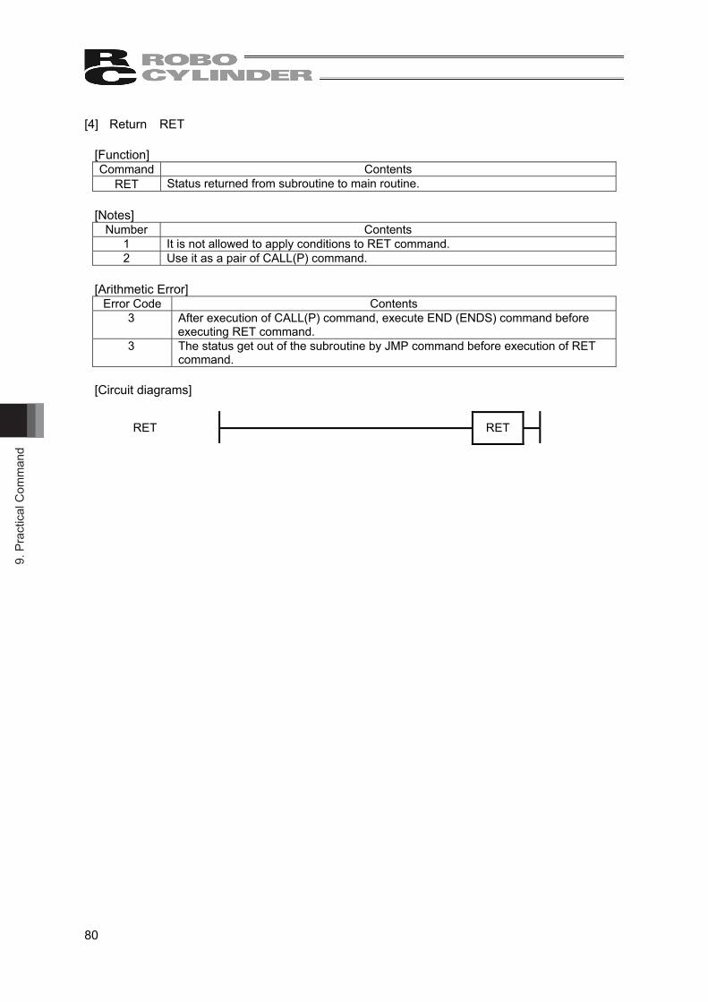
9. P
ract
ical
Com
man
d
80
[4] Return RET
[Function] Command Contents
RET Status returned from subroutine to main routine.
[Notes] Number Contents
1 It is not allowed to apply conditions to RET command. 2 Use it as a pair of CALL(P) command.
[Arithmetic Error]
Error Code Contents 3 After execution of CALL(P) command, execute END (ENDS) command before
executing RET command. 3 The status get out of the subroutine by JMP command before execution of RET
command.
[Circuit diagrams]
RET
RET

9. Practical Com
mand
81
9.2.6 Logical Operation Command [1] Logical Conjunction LAND(P)(2)
[Function] Command Contents LAND(2) Conduct the logical conjunction on the 16-bit data in the memory (OM) indicated in D
and the 16-bit data in the memory (OM) indicated in S for each bit, and store the result in the memory (OM) indicated in D. The value more than the digit indicated in the bit memory (OM) is defined as 0 in the arithmetic operation.
LANDP(2) LAND(2) is executed when a change is made to the arithmetic result from OFF to ON.
[Available Memory (OM)]
Bit Word Constant Label X Y M SM T C D SD T C IX DEC HEX L
WL Indication Index
S ○ ○ ○ ○ ○ ○ ○ ○ ○ ○ ○ ○ ○ D ○ ○ ○ ○ ○ ○ ○ ○ ○ ○
[Circuit diagrams]
LAND(2)
LAND S D
LANDP(2)
LANDP S D

9. P
ract
ical
Com
man
d
82
[2] Logical Conjunction LAND(P)(3)
[Function] Command Contents LAND(3) Conduct the logical conjunction on the 16-bit data in the memory (OM) indicated in
S1 and the 16-bit data in the memory (OM) indicated in S2 for each bit, and store the result in the memory (OM) indicated in D. The value more than the digit indicated in the bit memory (OM) is defined as 0 in the arithmetic operation.
LANDP(3) LAND(3) is executed when a change is made to the arithmetic result from OFF to ON.
[Available Memory (OM)]
Bit Word Constant Label X Y M SM T C D SD T C IX DEC HEX L
WL Indication Index
S1 ○ ○ ○ ○ ○ ○ ○ ○ ○ ○ ○ ○ ○ S2 ○ ○ ○ ○ ○ ○ ○ ○ ○ ○ ○ ○ D ○ ○ ○ ○ ○ ○ ○ ○ ○ ○
[Circuit diagrams]
LAND(3)
LAND S1 S2 D
LANDP(3)
LANDP S1 S2 D

9. Practical Com
mand
83
[3] Logical Disjunction LOR(P)(2)
[Function] Command Contents
LOR(2) Conduct the logical disjunction on the 16-bit data in the memory (OM) indicated in D and the 16-bit data in the memory (OM) indicated in S for each bit, and store the result in the memory (OM) indicated in D. The value more than the digit indicated in the bit memory (OM) is defined as 0 in the arithmetic operation.
LORP(2) LOR(2) is executed when a change is made to the arithmetic result from OFF to ON.
[Available Memory (OM)] Bit Word Constant Label
X Y M SM T C D SD T C IX DEC HEX L WL
Indication Index
S ○ ○ ○ ○ ○ ○ ○ ○ ○ ○ ○ ○ ○ D ○ ○ ○ ○ ○ ○ ○ ○ ○ ○
[Circuit diagrams]
LOR(2)
LOR S D
LORP(2)
LORP S D
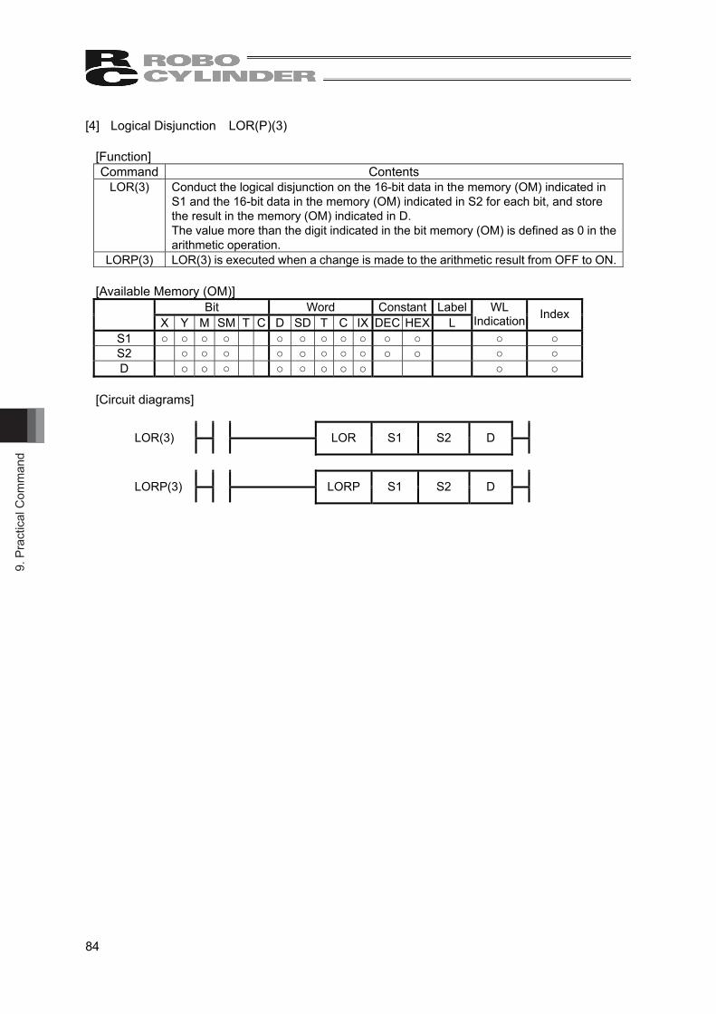
9. P
ract
ical
Com
man
d
84
[4] Logical Disjunction LOR(P)(3)
[Function] Command Contents
LOR(3) Conduct the logical disjunction on the 16-bit data in the memory (OM) indicated in S1 and the 16-bit data in the memory (OM) indicated in S2 for each bit, and store the result in the memory (OM) indicated in D. The value more than the digit indicated in the bit memory (OM) is defined as 0 in the arithmetic operation.
LORP(3) LOR(3) is executed when a change is made to the arithmetic result from OFF to ON.
[Available Memory (OM)] Bit Word Constant Label
X Y M SM T C D SD T C IX DEC HEX L WL
Indication Index
S1 ○ ○ ○ ○ ○ ○ ○ ○ ○ ○ ○ ○ ○ S2 ○ ○ ○ ○ ○ ○ ○ ○ ○ ○ ○ ○ D ○ ○ ○ ○ ○ ○ ○ ○ ○ ○
[Circuit diagrams]
LOR(3)
LOR S1 S2 D
LORP(3)
LORP S1 S2 D
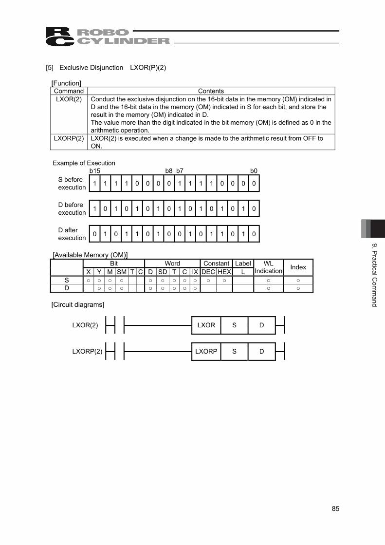
9. Practical Com
mand
85
[5] Exclusive Disjunction LXOR(P)(2)
[Function] Command Contents LXOR(2) Conduct the exclusive disjunction on the 16-bit data in the memory (OM) indicated in
D and the 16-bit data in the memory (OM) indicated in S for each bit, and store the result in the memory (OM) indicated in D. The value more than the digit indicated in the bit memory (OM) is defined as 0 in the arithmetic operation.
LXORP(2) LXOR(2) is executed when a change is made to the arithmetic result from OFF to ON.
Example of Execution
b15 b8 b7 b0 S before execution 1 1 1 1 0 0 0 0 1 1 1 1 0 0 0 0
D before execution 1 0 1 0 1 0 1 0 1 0 1 0 1 0 1 0
D after execution 0 1 0 1 1 0 1 0 0 1 0 1 1 0 1 0
[Available Memory (OM)] Bit Word Constant Label
X Y M SM T C D SD T C IX DEC HEX L WL
Indication Index
S ○ ○ ○ ○ ○ ○ ○ ○ ○ ○ ○ ○ ○ D ○ ○ ○ ○ ○ ○ ○ ○ ○ ○
[Circuit diagrams]
LXOR(2)
LXOR S D
LXORP(2)
LXORP S D
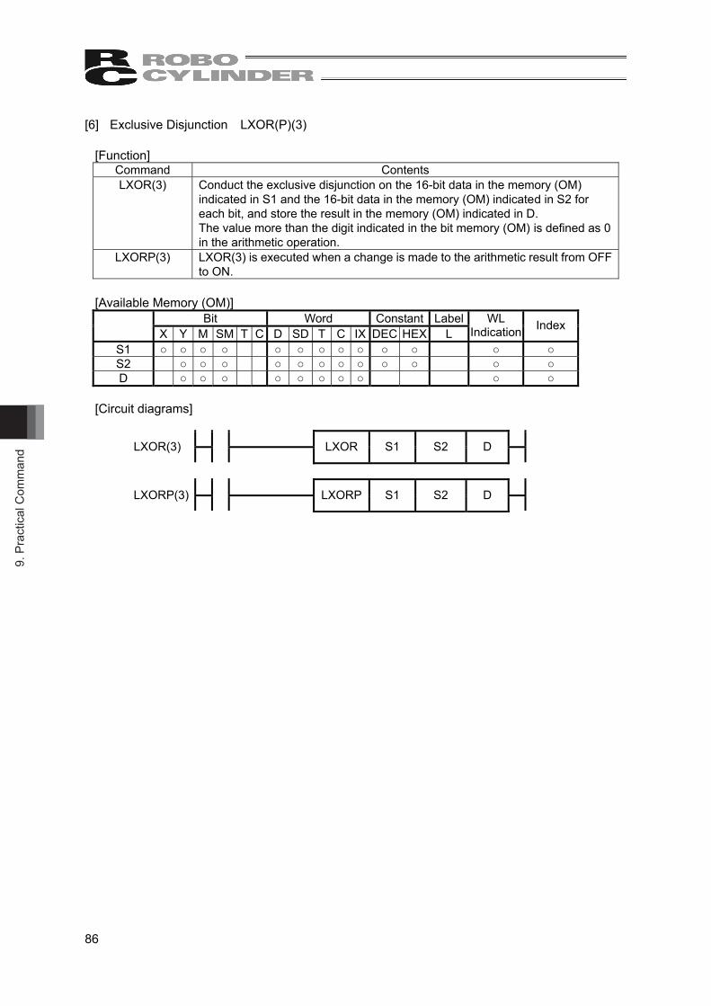
9. P
ract
ical
Com
man
d
86
[6] Exclusive Disjunction LXOR(P)(3)
[Function] Command Contents LXOR(3) Conduct the exclusive disjunction on the 16-bit data in the memory (OM)
indicated in S1 and the 16-bit data in the memory (OM) indicated in S2 for each bit, and store the result in the memory (OM) indicated in D. The value more than the digit indicated in the bit memory (OM) is defined as 0 in the arithmetic operation.
LXORP(3) LXOR(3) is executed when a change is made to the arithmetic result from OFF to ON.
[Available Memory (OM)]
Bit Word Constant Label X Y M SM T C D SD T C IX DEC HEX L
WL Indication Index
S1 ○ ○ ○ ○ ○ ○ ○ ○ ○ ○ ○ ○ ○ S2 ○ ○ ○ ○ ○ ○ ○ ○ ○ ○ ○ ○ D ○ ○ ○ ○ ○ ○ ○ ○ ○ ○
[Circuit diagrams]
LXOR(3)
LXOR S1 S2 D
LXORP(3)
LXORP S1 S2 D

9. Practical Com
mand
87
[7] Exclusive NOR LXNR(P)(2) [Function] Command Contents LXNR(2) Conduct the exclusive NOR on the 16-bit data in the memory (OM) indicated in D
and the 16-bit data in the memory (OM) indicated in S for each bit, and store the result in the memory (OM) indicated in D. The value more than the digit indicated in the bit memory (OM) is defined as 0 in the arithmetic operation.
LXNRP(2) LXNR(2) is executed when a change is made to the arithmetic result from OFF to ON.
Example of Execution
b15 b8 b7 b0 S before execution 1 1 1 1 0 0 0 0 1 1 1 1 0 0 0 0
D before execution 1 0 1 0 1 0 1 0 1 0 1 0 1 0 1 0
D after execution 1 0 1 0 0 1 0 1 1 0 1 0 0 1 0 1
[Available Memory (OM)] Bit Word Constant Label
X Y M SM T C D SD T C IX DEC HEX L WL
Indication Index
S ○ ○ ○ ○ ○ ○ ○ ○ ○ ○ ○ ○ ○ D ○ ○ ○ ○ ○ ○ ○ ○ ○ ○
[Circuit diagrams]
LXNR(2)
LXNR S D
LXNRP(2)
LXNRP S D

9. P
ract
ical
Com
man
d
88
[8] Exclusive NOR LXNR(P)(3)
[Function] Command Contents LXNR(3) Conduct the exclusive NOR on the 16-bit data in the memory (OM) indicated in S1
and the 16-bit data in the memory (OM) indicated in S2 for each bit, and store the result in the memory (OM) indicated in D. The value more than the digit indicated in the bit memory (OM) is defined as 0 in the arithmetic operation.
LXNRP(3) LXNR(3) is executed when a change is made to the arithmetic result from OFF to ON.
[Available Memory (OM)]
Bit Word Constant Label X Y M SM T C D SD Y C IX DEC HEX L
WL Indication Index
S1 ○ ○ ○ ○ ○ ○ ○ ○ ○ ○ ○ ○ ○ S2 ○ ○ ○ ○ ○ ○ ○ ○ ○ ○ ○ ○ D ○ ○ ○ ○ ○ ○ ○ ○ ○ ○
[Circuit diagrams]
LXNR(3)
LXNR S1 S2 D
LXNRP(3)
LXNRP S1 S2 D

9. Practical Com
mand
89
[9] Symbol Reverse NEG(P)
[Function] Command Contents
NEG The sign in the 16-bit memory (OM) indicated in D is reversed, and stored in the memory (OM) indicated in D. It is used when reversing the sign of positive and negative.
NEGP NEG is executed when a change is made to the arithmetic result from OFF to ON. Example of Execution
b15 b8 b7 b0 D before execution 1 1 0 1 1 0 0 0 1 1 1 1 0 0 0 0 -10000(D8F0h)
D after execution 0 0 1 0 0 1 1 1 0 0 0 1 0 0 0 0 +10000(2710h)
[Available Memory (OM)] Bit Word Constant Label
X Y M SM T C D SD T C IX DEC HEX L WL
Indication (Note 1)
Index
○ ○ ○ ○ ○ ○ ○ ○ ○ ○ Note 1 Bit memory (OM) is available only for multiple bit access (16 bits at maximum).
The word memory (OM) cannot perform 32-bit access.
[Circuit diagrams]
NEG
NEG D
NEGP
NEGP D
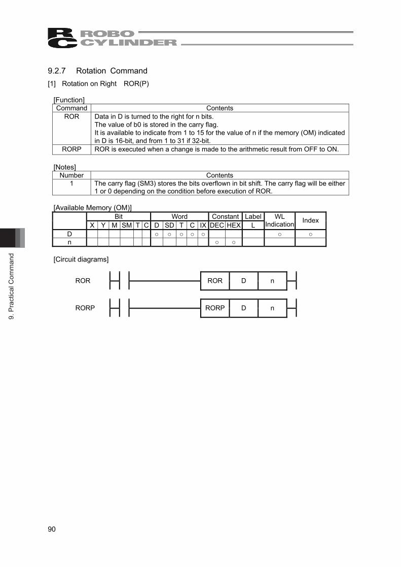
9. P
ract
ical
Com
man
d
90
9.2.7 Rotation Command [1] Rotation on Right ROR(P)
[Function] Command Contents
ROR Data in D is turned to the right for n bits. The value of b0 is stored in the carry flag. It is available to indicate from 1 to 15 for the value of n if the memory (OM) indicated in D is 16-bit, and from 1 to 31 if 32-bit.
RORP ROR is executed when a change is made to the arithmetic result from OFF to ON. [Notes]
Number Contents 1 The carry flag (SM3) stores the bits overflown in bit shift. The carry flag will be either
1 or 0 depending on the condition before execution of ROR.
[Available Memory (OM)] Bit Word Constant Label
X Y M SM T C D SD T C IX DEC HEX L WL
Indication Index
D ○ ○ ○ ○ ○ ○ ○ n ○ ○
[Circuit diagrams]
ROR
ROR D n
RORP
RORP D n

9. Practical Com
mand
91
[Example for Programming] It is an example for turning D0 to the right for 3 bits when X0 is turned ON.
X0 0
ROR D0 3
Carry Flag (when carry flag before execution is 1)
b15 b8 b7 b0 Carry Flag (SM3) D0 before execution 0 0 0 0 0 0 0 0 0 0 0 0 0 1 0 1 1
(N=1) 1 0 0 0 0 0 0 0 0 0 0 0 0 0 1 0 1 (N=2) 0 1 0 0 0 0 0 0 0 0 0 0 0 0 0 1 0
D0 after execution 1 0 1 0 0 0 0 0 0 0 0 0 0 0 0 0 1
(N=3)
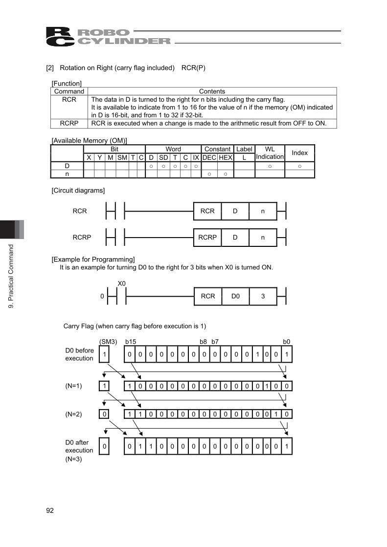
9. P
ract
ical
Com
man
d
92
[2] Rotation on Right (carry flag included) RCR(P)
[Function] Command Contents
RCR The data in D is turned to the right for n bits including the carry flag. It is available to indicate from 1 to 16 for the value of n if the memory (OM) indicated in D is 16-bit, and from 1 to 32 if 32-bit.
RCRP RCR is executed when a change is made to the arithmetic result from OFF to ON.
[Available Memory (OM)] Bit Word Constant Label
X Y M SM T C D SD T C IX DEC HEX L WL
Indication Index
D ○ ○ ○ ○ ○ ○ ○ n ○ ○
[Circuit diagrams]
RCR
RCR D n
RCRP
RCRP D n
[Example for Programming] It is an example for turning D0 to the right for 3 bits when X0 is turned ON.
X0 0
RCR D0 3
Carry Flag (when carry flag before execution is 1)
(SM3) b15 b8 b7 b0 D0 before execution 1 0 0 0 0 0 0 0 0 0 0 0 0 1 0 0 1
(N=1) 1 1 0 0 0 0 0 0 0 0 0 0 0 0 1 0 0 (N=2) 0 1 1 0 0 0 0 0 0 0 0 0 0 0 0 1 0
D0 after execution 0 0 1 1 0 0 0 0 0 0 0 0 0 0 0 0 1
(N=3)

9. Practical Com
mand
93
[3] Rotation on Left ROL(P) [Function] Command Contents
ROL Data in D is turned to the left for n bits. The value of b15 is stored in the carry flag. It is available to indicate from 1 to 15 or the value of n if the memory (OM) indicated in D is 16-bit, and from 1 to 31 if 32-bit.
ROLP ROL is executed when a change is made to the arithmetic result from OFF to ON. [Available Memory (OM)]
Bit Word Constant Label X Y M SM T C D SD T C IX DEC HEX L
WL Indication Index
D ○ ○ ○ ○ ○ ○ ○ n ○ ○
[Circuit diagrams]
ROL
ROL D n
ROLP
ROLP D n
[Example for Programming] It is an example for turning D0 to the left for 3 bits when X0 is turned ON.
X0 0
ROL D0 3
Carry Flag (when carry flag before execution is 1)
(SM3) b15 b8 b7 b0 D0 before execution 1 1 0 0 0 0 0 0 0 0 0 0 0 0 0 0 0
(N=1) 1 0 0 0 0 0 0 0 0 0 0 0 0 0 0 0 1 (N=2) 0 0 0 0 0 0 0 0 0 0 0 0 0 0 0 1 0 D0 after execution 0 0 0 0 0 0 0 0 0 0 0 0 0 0 1 0 0
(N=3)

9. P
ract
ical
Com
man
d
94
[4] Rotation on Left (carry flag included) RCL(P)
[Function] Command Contents
RCL The data in D is turned to the left for n bits including the carry flag. It is available to indicate from 1 to 16 for the value of n if the memory (OM) indicated in D is 16-bit, and from 1 to 32 if 32-bit.
RCLP RCL is executed when a change is made to the arithmetic result from OFF to ON.
[Available Memory (OM)] Bit Word Constant Label
X Y M SM T C D SD T C IX DEC HEX L WL
Indication Index
D ○ ○ ○ ○ ○ ○ ○ n ○ ○
[Circuit diagrams]
RCL
RCL D n
RCLP
RCLP D n
[Example for Programming] It is an example for turning D0 to the left for 3 bits when X0 is turned ON.
X0 0
RCL D0 3
Carry Flag (when carry flag before execution is 1)
(SM3) b15 b8 b7 b0 D0 before execution 1 1 0 1 0 0 0 0 0 0 0 0 0 0 0 0 0
(N=1) 1 0 1 0 0 0 0 0 0 0 0 0 0 0 0 0 1 (N=2) 0 1 0 0 0 0 0 0 0 0 0 0 0 0 0 1 1 D0 after execution 1 0 0 0 0 0 0 0 0 0 0 0 0 0 1 1 0
(N=3)

9. Practical Com
mand
95
9.2.8 Shift Command [1] Shift to Right for n Bits SHR(P)
[Function] Command Contents
SHR The 16-bit data in the word memory (OM) indicated in D or 16 bits (16 points) at maximum in the bit memory (OM) is shifted to the right for n bits. n bits from the highest is 0. The value in nth bit is stored in the carry flag. The shift for timer and counter is the shift of the current value (calculated value or counted value).
SHRP SHR is executed when a change is made to the arithmetic result from OFF to ON. [Notes]
Number Contents 1 32-bit data cannot be indicated in D. (It can cause the editor input error.)
[Available Memory (OM)]
Bit Word Constant Label
X Y M SM T C D SD T C IX DEC HEX L WL
Indication (Note 1)
Index
D ○ ○ ○ ○ ○ ○ ○ ○ ○ ○ n ○ ○
Note 1 Bit memory (OM) is available only for multiple bit access (16 bits at maximum). The word memory (OM) cannot perform 32-bit access.
[Circuit diagrams]
SHR
SHR D n
SHRP
SHRP D n
[Example for Programming] It is an example for shifting D0 to the right for 3 bits when X0 is turned ON.
X0 0
SHR D0 3
Carry Flag (when carry flag before execution is 1) Carry Flag b15 b8 b7 b0 (SM3)
D0 before execution 0 0 0 0 0 0 0 0 0 0 0 1 1 0 0 0 1 (when flag before
execution is 1) D0 after execution 0 0 0 0 0 0 0 0 0 0 0 0 0 0 1 1 0
0 is stored in 3 bits from the highest
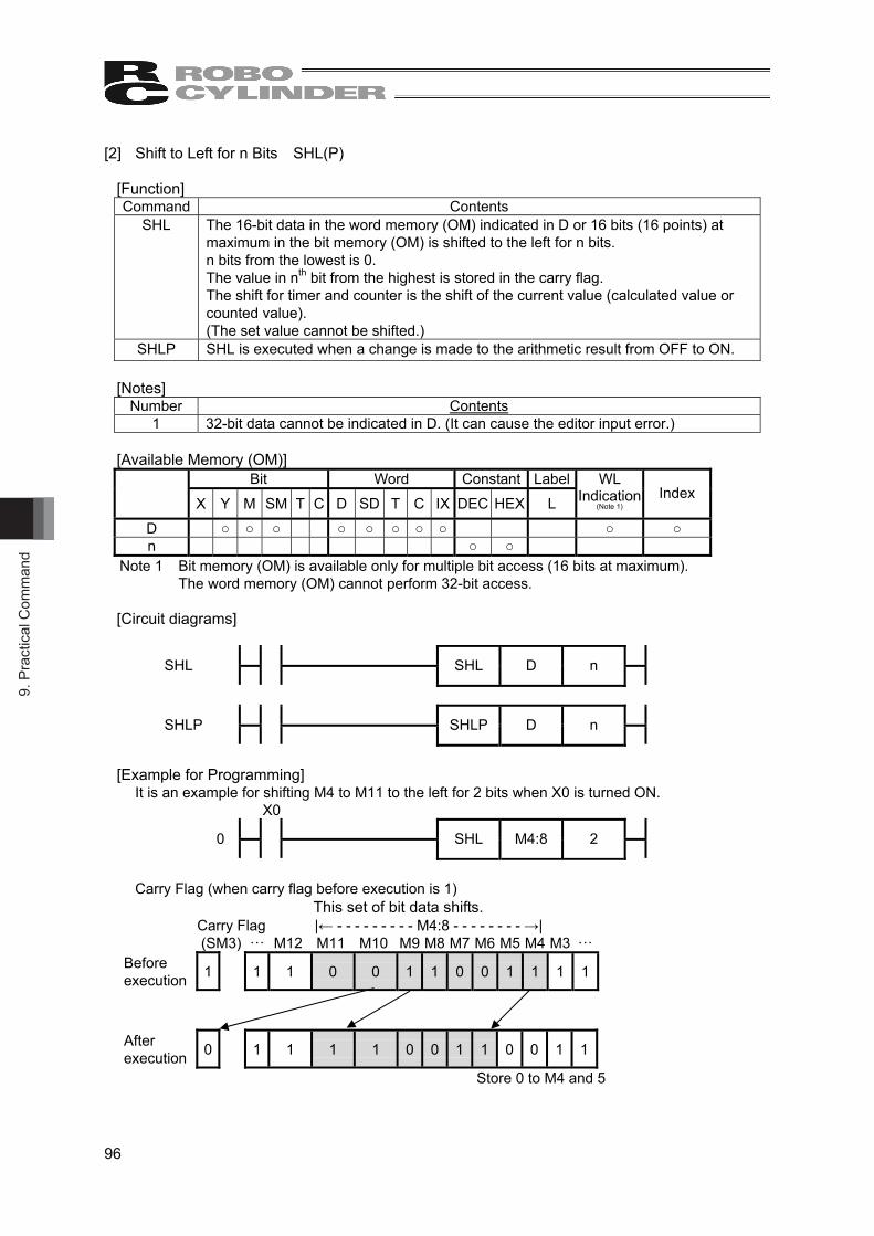
9. P
ract
ical
Com
man
d
96
[2] Shift to Left for n Bits SHL(P)
[Function] Command Contents
SHL The 16-bit data in the word memory (OM) indicated in D or 16 bits (16 points) at maximum in the bit memory (OM) is shifted to the left for n bits. n bits from the lowest is 0. The value in nth bit from the highest is stored in the carry flag. The shift for timer and counter is the shift of the current value (calculated value or counted value). (The set value cannot be shifted.)
SHLP SHL is executed when a change is made to the arithmetic result from OFF to ON. [Notes]
Number Contents 1 32-bit data cannot be indicated in D. (It can cause the editor input error.)
[Available Memory (OM)]
Bit Word Constant Label
X Y M SM T C D SD T C IX DEC HEX L WL
Indication (Note 1)
Index
D ○ ○ ○ ○ ○ ○ ○ ○ ○ ○ n ○ ○
Note 1 Bit memory (OM) is available only for multiple bit access (16 bits at maximum). The word memory (OM) cannot perform 32-bit access.
[Circuit diagrams]
SHL
SHL D n
SHLP
SHLP D n
[Example for Programming] It is an example for shifting M4 to M11 to the left for 2 bits when X0 is turned ON.
X0 0
SHL M4:8 2
Carry Flag (when carry flag before execution is 1)
Carry Flag |← - - - - - - - - - M4:8 - - - - - - - - →| (SM3) ꞏꞏꞏ M12 M11 M10 M9 M8 M7 M6 M5 M4 M3 ꞏꞏꞏ Before execution 1 1 1 0 0 1 1 0 0 1 1 1 1
After execution 0 1 1 1 1 0 0 1 1 0 0 1 1
Store 0 to M4 and 5
This set of bit data shifts.
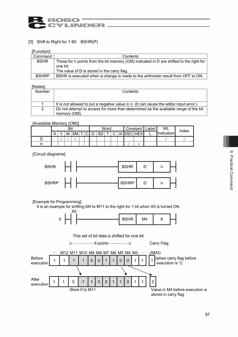
9. Practical Com
mand
97
[3] Shift to Right for 1 Bit BSHR(P)
[Function] Command Contents
BSHR Those for n points from the bit memory (OM) indicated in D are shifted to the right for one bit. The value of D is stored in the carry flag.
BSHRP BSHR is executed when a change is made to the arithmetic result from OFF to ON. [Notes]
Number Contents
1 It is not allowed to put a negative value in n. (It can cause the editor input error.) 2 Do not attempt to access for more than determined as the available range of the bit
memory (OM).
[Available Memory (OM)] Bit Word Constant Label
X Y M SM T C D SD T C IX DEC HEX L WL
Indication Index
D ○ ○ ○ ○ ○ n ○ ○
[Circuit diagrams]
BSHR
BSHR D n
BSHRP
BSHRP D n
[Example for Programming] It is an example for shifting M4 to M11 to the right for 1 bit when X0 is turned ON.
X0 0
BSHR M4 8
|← - - - - - - - - 8 points - - - - - - - →| Carry Flag
ꞏꞏꞏ M12 M11 M10 M9 M8 M7 M6 M5 M4 M3 ꞏꞏꞏ (SM3) Before execution 1 1 1 1 0 0 1 1 0 0 1 1 1 (when carry flag before
execution is 1)
After execution 1 1 0 1 1 0 0 1 1 0 1 1 0
Store 0 to M11 Value in M4 before execution is stored in carry flag
This set of bit data is shifted for one bit

9. P
ract
ical
Com
man
d
98
[4] Shift to Left for 1 Bit BSHL(P)
[Function] Command Contents
BSHL With the bit memory (OM) indicated in D as the top, those for n points are shifted for one bit.
BSHLP BSHL is executed when a change is made to the arithmetic result from OFF to ON. [Notes]
Number Contents 1 It is not allowed to put a negative value in n. (It can cause the editor input error.) 2 Do not attempt to access for more than determined as the available range of the bit
memory (OM).
[Available Memory (OM)] Bit Word Constant Label
X Y M SM T C D SD T C IX DEC HEX L WL
Indication Index
D ○ ○ ○ ○ ○ n ○ ○
[Circuit diagrams]
BSHL
BSHL D n
BSHLP
BSHLP D n
[Example for Programming] It is an example for shifting M4 to M11 to the left for 1 bit when X0 is turned ON.
X0 0
BSHL M4 8
Carry Flag (when carry flag before execution is 1
Carry Flag |← - - - - - - - M4:8 points - - - - - - →| (SM32) ꞏꞏꞏ M12 M11 M10 M9 M8 M7 M6 M5 M4 M3 ꞏꞏꞏ Before execution 1 1 1 0 0 1 1 0 0 1 1 1 1
After execution 0 1 1 0 1 1 0 0 1 1 0 1 1
Value in M11 before execution is stored in carry flag
Store 0 to M4
This set of bit data is shifted for one bit

9. Practical Com
mand
99
[5] Shift to Right for 1 Word WSHR(P)
[Function] Command Contents
WSHR With the bit memory (OM) indicated in D as the top, those for n points are shifted to the right for one word. The word memory (OM) at the highest is 0. The shift for timer and counter is the shift of the current value (calculated value or counted value). (The set value cannot be shifted.)
WSHRP WSHR is executed when a change is made to the arithmetic result from OFF to ON. [Notes]
Number Contents 1 It is not allowed to put a negative value in n. (It can cause the editor input error.)
[Available Memory (OM)]
Bit Word Constant Label X Y M SM T C D SD T C IX DEC HEX L
WL Indication Index
D ○ ○ ○ ○ ○ n ○ ○
[Circuit diagrams]
WSHR
WSHR D n
WSHRP
WSHRP D n
[Example for Programming] It is an example for shifting D4 to D9 to the right for 1 word when X0 is turned ON.
X0 0
WSHR D4 6
|← - - - - - - - - - - 6 words - - - - - - - - - - - →| D10 D09 D08 D07 D06 D05 D04 D03
Before execution 27 -4 1 296 10263 1234 200 97
After execution 27 0 -4 1 296 10263 1234 97
Store 0 to D9
This set of word data is shifted for one word
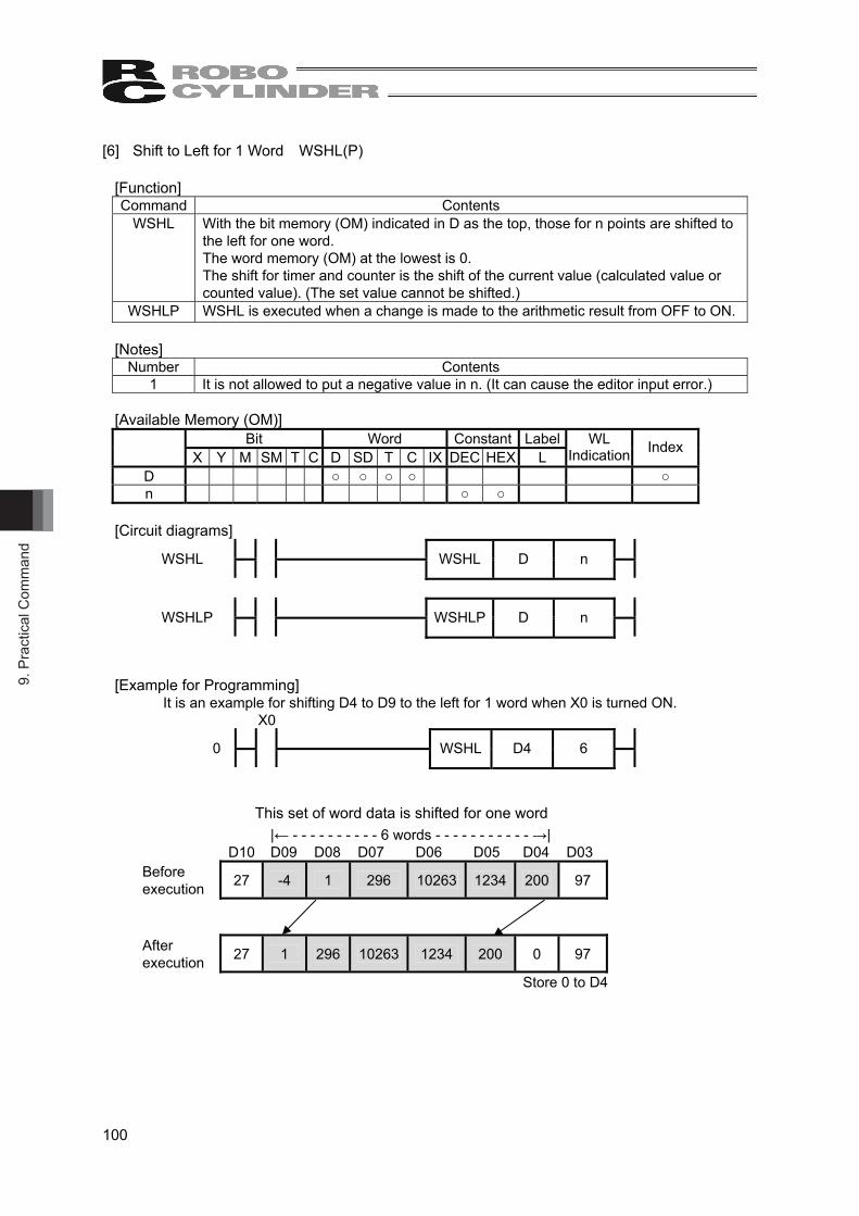
9. P
ract
ical
Com
man
d
100
[6] Shift to Left for 1 Word WSHL(P)
[Function] Command Contents
WSHL With the bit memory (OM) indicated in D as the top, those for n points are shifted to the left for one word. The word memory (OM) at the lowest is 0. The shift for timer and counter is the shift of the current value (calculated value or counted value). (The set value cannot be shifted.)
WSHLP WSHL is executed when a change is made to the arithmetic result from OFF to ON. [Notes]
Number Contents 1 It is not allowed to put a negative value in n. (It can cause the editor input error.)
[Available Memory (OM)]
Bit Word Constant Label X Y M SM T C D SD T C IX DEC HEX L
WL Indication Index
D ○ ○ ○ ○ ○ n ○ ○
[Circuit diagrams]
WSHL
WSHL D n
WSHLP
WSHLP D n
[Example for Programming] It is an example for shifting D4 to D9 to the left for 1 word when X0 is turned ON.
X0 0
WSHL D4 6
|← - - - - - - - - - - 6 words - - - - - - - - - - - →| D10 D09 D08 D07 D06 D05 D04 D03
Before execution 27 -4 1 296 10263 1234 200 97
After execution 27 1 296 10263 1234 200 0 97
Store 0 to D4
This set of word data is shifted for one word

9. Practical Com
mand
101
9.2.9 Data Process Command [1] Bit Check SUM(P)
[Function] Command Contents
SUM The total number of the bits (BIN data) with 1 in the data in the memory (MO) indicated in S is stored in the memory (MO) indicated in D.
SUMP SUM is executed when a change is made to the arithmetic result from OFF to ON.
Example of Execution b15 b8 b7 b0
S 1 1 0 0 1 1 0 1 1 0 0 1 1 0 0 0 In this case, 8 is stored in D.
[Available Memory (OM)] Bit Word Constant Label
X Y M SM T C D SD T C IX DEC HEX L WL
Indication Index
S ○ ○ ○ ○ ○ ○ ○ ○ ○ ○ ○ D ○ ○ ○ ○ ○ ○
[Circuit diagrams]
SUM
SUM S D
SUMP
SUMP S D

9. P
ract
ical
Com
man
d
102
[2] 8 → 256-Bit Decoding DECO(P)
[Function] Command Contents
DECO The low n bit in the memory (OM) indicated in S is decoded, and the resulted decode data is stored in the 2n bit from the memory (OM) indicated in D (8 to 256-bit decoding). From 0 to 8 are available to indicate in n. When n = 0, there is no process, thus no change is made to the contents in the 2n bit from the memory (OM) indicated in D. Bit memory (OM) is treated as 1-bit and word memory (OM) as 16-bit.
DECOP DECO is executed when a change is made to the arithmetic result from OFF to ON.
[Available Memory (OM)] Bit Word Constant Label
X Y M SM T C D SD T C IX DEC HEX L WL
Indication Index
S ○ ○ ○ ○ ○ ○ ○ ○ ○ ○ ○ ○ D ○ ○ ○ ○ ○ ○ ○ ○ n ○ ○
[Arithmetic Error]
Error Code Contents 5 When n is other than those from 0 to 8.
[Circuit diagrams]
DECO
DECO S D n
DECOP
DECOP S D n
[Example for Programming] It is an example for a case to make X10 to X12 decoded and M0 to M7 stored when X0 is turned ON.
X0 0
DECO X10 M0 3
X12 X11 X10 S 1 0 1 M5 in the 5th bit from M0 is turned ON M07 M06 M05 M04 M03 M02 M01 M00 D 0 0 1 0 0 0 0 0 Store result in 23 bit (8-bit) from M0

9. Practical Com
mand
103
[3] 256→8 Bit Encoding ENCO(P)
[Function] Command Contents
ENCO The data in the 2n bit from S is encoded, and stored in D (256 to 8-bit encoding). From 0 to 8 are available to indicate in n. When n = 0, there is no process, thus no change is made to the contents in D. Bit memory (OM) is treated as 1-bit and word memory (OM) as 16-bit. When 1 is set in multiple bits in S, it is processed in the highest bit position.
ENCOP ENCO is executed when a change is made to the arithmetic result from OFF to ON.
[Available Memory (OM)] Bit Word Constant Label
X Y M SM T C D SD T C IX DEC HEX L
WL Indication
(Note 1) Index
S ○ ○ ○ ○ ○ ○ ○ ○ ○ ○ D ○ ○ ○ ○ ○ ○ n ○ ○
Note 1 Bit memory (OM) is available only for multiple bit access (16 bits at maximum). The word memory (OM) cannot perform 32-bit access.
[Arithmetic Error]
Error Code Contents 5 When all from S to 2n bits are 0. 5 When n is other than those from 0 to 8.
[Circuit diagrams]
ENCO
ENCO S D n
ENCOP
ENCOP S D n
[Example for Programming] It is an example for a case to make M0 to M7 encoded and D0 stored when X0 is turned ON.
X0 0
ENCO M0 D0 3
From M0 to 23 bits (8 bits) M7 M6 M5 M4 M3 M2 M1 M0 S 0 0 1 0 0 0 0 0
Information what number of bit from M0 is turned on is stored in D0
D0 0 0 0 0 0 0 0 0 0 0 0 0 0 1 0 1 Store 5 with BIN

9. P
ract
ical
Com
man
d
104
[4] Bit Set BSET(P)
[Function] Command Contents
BSET Set (to 1) the nth bit in the word memory (OM) indicated in D. The effective values in n are from 0 to 15.
BSETP BSET is executed when a change is made to the arithmetic result from OFF to ON.
[Notes] Number Contents
1 It is not allowed to set a number out of the range for n. (It can cause the editor input error.)
[Available Memory (OM)]
Bit Word Constant Label X Y M SM T C D SD T C IX DEC HEX L
WL Indication Index
D ○ ○ ○ ○ ○ ○ n ○ ○
[Circuit diagrams]
BSET
BSET D n
BSETP
BSETP D n
[Example for Programming] It is an example for setting the 3rd bit in D0 when X0 is turned ON.
X0 0
BSET D0 3
b15 b3 b0 D0 before execution 0 0 1 1 0 0 1 1 0 0 1 1 0 0 1 1
Set the 3rd bit
D0 after execution 0 0 1 1 0 0 1 1 0 0 1 1 1 0 1 1
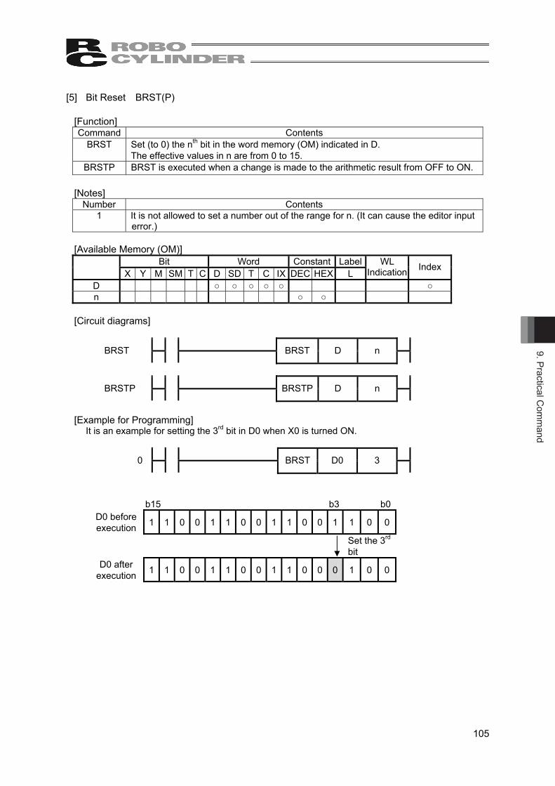
9. Practical Com
mand
105
[5] Bit Reset BRST(P)
[Function] Command Contents
BRST Set (to 0) the nth bit in the word memory (OM) indicated in D. The effective values in n are from 0 to 15.
BRSTP BRST is executed when a change is made to the arithmetic result from OFF to ON.
[Notes] Number Contents
1 It is not allowed to set a number out of the range for n. (It can cause the editor input error.)
[Available Memory (OM)]
Bit Word Constant Label X Y M SM T C D SD T C IX DEC HEX L
WL Indication Index
D ○ ○ ○ ○ ○ ○ n ○ ○
[Circuit diagrams]
BRST
BRST D n
BRSTP
BRSTP D n
[Example for Programming] It is an example for setting the 3rd bit in D0 when X0 is turned ON.
0
BRST D0 3
b15 b3 b0 D0 before execution 1 1 0 0 1 1 0 0 1 1 0 0 1 1 0 0
Set the 3rd bit
D0 after execution 1 1 0 0 1 1 0 0 1 1 0 0 0 1 0 0

9. P
ract
ical
Com
man
d
106
[6] 4-bit Separation of 16-bit Data DDV(P)
[Function] Command Contents
DDV The data for the low n digits (4 bits for 1 digit) in 16-bit indicated in S is stored in the low 4 bits for n points from the memory (OM) indicated in D. The higher 12 bits in n points from OM indicated in D are 0. From 0 to 4 are available to indicate in n.
DDVP DDV is executed when a change is made to the arithmetic result from OFF to ON.
[Notes] Number Contents
1 It is not allowed to set a number out of the range for n. (It can cause the editor input error.)
[Available Memory (OM)]
Bit Word Constant Label X Y M SM T C D SD T C IX DEC HEX L
WL Indication Index
S ○ ○ ○ ○ ○ ○ ○ ○ D ○ ○ ○ ○ ○ n ○ ○
[Circuit diagrams]
DDV
DDV S D n
DDVP
DDVP S D n
[Example for Programming] It is an example for storing each digit (4 bits) in D0 in D10 to D13 when X0 is turned ON.
X0
0
DDV D0 D10 4
b15-b12 b11-b8 b7-b4 b3-b0 D10 to D13 after execution
D0 1 0 0 1 0 1 0 1 0 1 1 0 0 0 0 1 b15-b4 b3-b0
D10 0 0 0 0 1
D11 0 0 1 1 0
D12 0 0 1 0 1
D13 0 1 0 0 1

9. Practical Com
mand
107
[7] 4-bit Merge of 16-bit Data DCV(P)
[Function] Command Contents
DCV The low 4 bits in the 16-bit data in n points from the memory (OM) indicated in S is merged with the 16-bit memory (OM) indicated in D. The higher bits of digits of (16 - n 4) in the memory (OM) dedicated in D are 0. From 0 to 4 are available to indicate in n.
DCVP DCV is executed when a change is made to the arithmetic result from OFF to ON.
[Notes] Number Contents
1 It is not allowed to set a number out of the range for n. (It can cause the editor input error.)
[Available Memory (OM)]
Bit Word Constant Label X Y M SM T C D SD T C IX DEC HEX L
WL Indication Index
S ○ ○ ○ ○ ○ D ○ ○ ○ ○ ○ ○ n ○ ○
[Circuit diagrams]
DCV
DCV S D n
DCVP
DCVP S D n
[Example for Programming] It is an example for storing the low 4 bits in D0 to D2 to D10 when X0 is turned ON.
0
DCV D0 D10 3
D10 after execution b15-b12 b11-b8 b7-b4 b3-b0 b15-b4 b3-b0 D10 0 0 0 0 0 1 1 0 1 0 0 0 0 0 0 1
D0 Ignore 0 0 0 1
D1 Ignore 0 1 0 0
D2 Ignore 0 1 1 0
Store 0

9. P
ract
ical
Com
man
d
108
9.2.10 FIFO Command [1] Writing in FIFO Table FIFW(P)
[Function] Command Contents
FIFW 1) The data indicated in S is stored in the data table in FIFO Table. Data storage position = Top address in data table + Pointer contents
2) Add +1 to pointer contents (The pointer uses the memory (OM) indicated in D.) FIFWP FIFW is executed when a change is made to the arithmetic result from OFF to ON.
FIFO Table Construction D n
Number of sets of data (pointers) stored in data table
Data Table Top D+1 D+2 Data Table ・・・ ・・・ Data is stored by FIFW(P) Command.
D+n If FIFW(P) Command is executed, the condition becomes as follows;
D n+1
Pointer is added +1.
Data Table Top D+1 D+2 ・・・ ・・・
D+n
D+n+1 Data in S
Data in S is stored in D + n + 1.
[Notes]
Number Contents 1 When executing FIFW Command for the first time, clear the pointer indicated in D to 0. 2 When writing into multiple FIFO Tables, control the number of sets of data.
[Available Memory (OM)]
Bit Word Constant Label
X Y M SM T C D SD T C IX DEC HEX L WL
Indication (Note 1)
Index
S ○ ○ ○ ○ ○ ○ ○ ○ ○ ○ ○ ○ D ○ ○ ○ ○ ○
Note 1 S is available only for multiple bit access (16 bits at maximum) of the bit memory (OM).
[Arithmetic Error] Error Code Contents
5 When the top address in FIFO Table + Pointer contents exceeds the applicable device range.

9. Practical Com
mand
109
[Circuit diagrams]
FIFW
FIFW S D
FIFWP
FIFWP S D
[Example for Programming] It is an example for storing the data of X0 to X15 to FIFO Table (from D0) when X0 is turned ON.
X0 0
FIFW X0W D0
Assume that there are three sets of data in FIFO Table before execution. Before execution After execution
D0 3 Pointer D0 4 D0 is added +1
D1 100 Top D1 100
D2 200 D2 200
D3 300 D3 300 D4 D4 400 400 is stored in D4.
X0-X15 400 X0-X15 400 There is no change to X0 to X15.
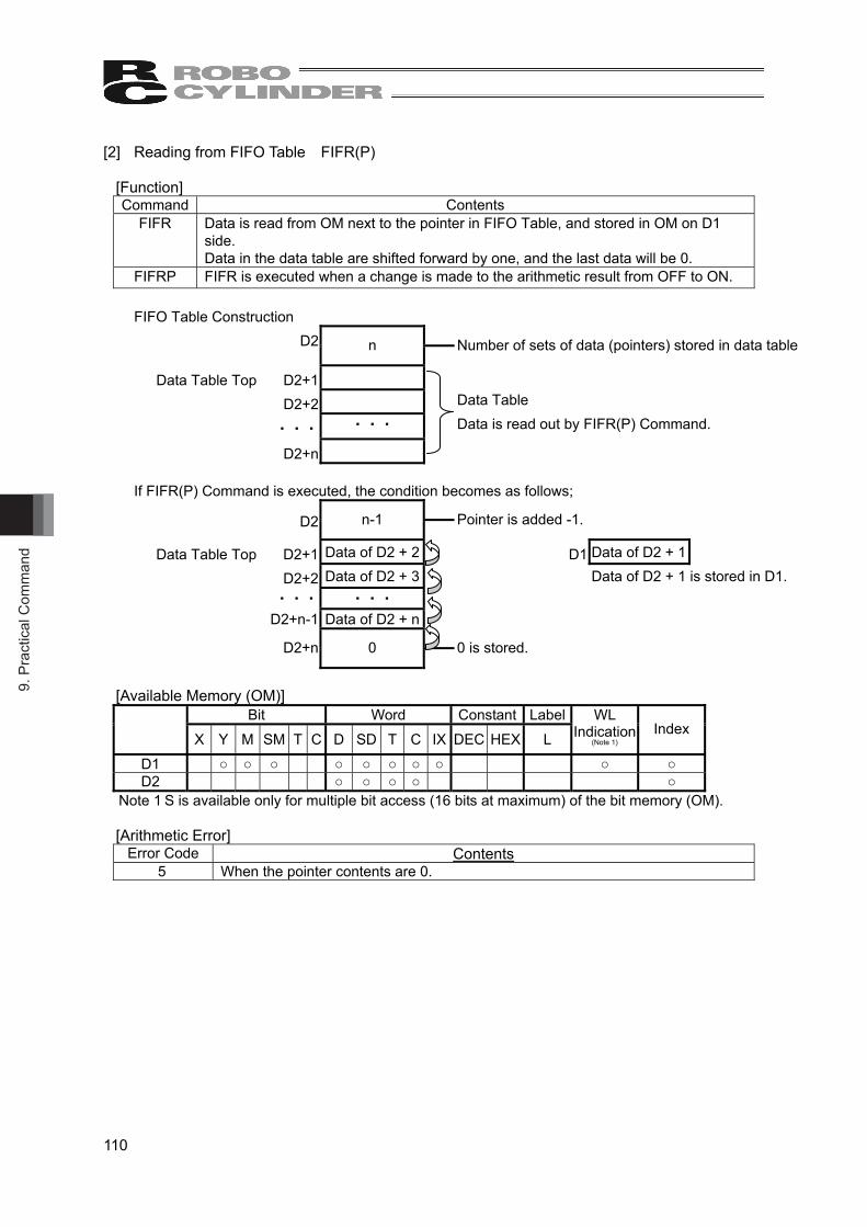
9. P
ract
ical
Com
man
d
110
[2] Reading from FIFO Table FIFR(P)
[Function] Command Contents
FIFR Data is read from OM next to the pointer in FIFO Table, and stored in OM on D1 side. Data in the data table are shifted forward by one, and the last data will be 0.
FIFRP FIFR is executed when a change is made to the arithmetic result from OFF to ON.
FIFO Table Construction D2 n
Number of sets of data (pointers) stored in data table
Data Table Top D2+1 D2+2 Data Table ・・・ ・・・ Data is read out by FIFR(P) Command.
D2+n If FIFR(P) Command is executed, the condition becomes as follows;
D2 n-1
Pointer is added -1.
Data Table Top D2+1 Data of D2 + 2 D1 Data of D2 + 1 D2+2 Data of D2 + 3 Data of D2 + 1 is stored in D1. ・・・ ・・・ D2+n-1 Data of D2 + n
D2+n 0
0 is stored.
[Available Memory (OM)]
Bit Word Constant Label
X Y M SM T C D SD T C IX DEC HEX L WL
Indication (Note 1)
Index
D1 ○ ○ ○ ○ ○ ○ ○ ○ ○ ○ D2 ○ ○ ○ ○ ○
Note 1 S is available only for multiple bit access (16 bits at maximum) of the bit memory (OM).
[Arithmetic Error] Error Code Contents
5 When the pointer contents are 0.

9. Practical Com
mand
111
[Circuit diagrams]
FIFR
FIFR D1 D2
FIFRP
FIFRP D1 D2
[Example for Programming] It is an example for reading out the data from FIFO table (from D0) and store data in Y0 to Y15 when X0 is turned ON.
X0 0
FIFR Y0W D0
Assume that there are three sets of data in FIFO Table before execution. Before execution After execution
D0 3 Pointer D0 2 D0 is added -1.
D1 100 Top D1 200
D2 200 D2 300
D3 300 D3 0 0 is stored in D3. Y0-Y15 100 Data in D1 (table top) is stored.
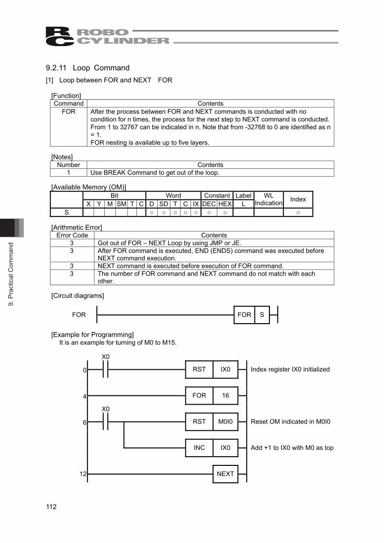
9. P
ract
ical
Com
man
d
112
9.2.11 Loop Command [1] Loop between FOR and NEXT FOR
[Function] Command Contents
FOR After the process between FOR and NEXT commands is conducted with no condition for n times, the process for the next step to NEXT command is conducted. From 1 to 32767 can be indicated in n. Note that from -32768 to 0 are identified as n = 1. FOR nesting is available up to five layers.
[Notes]
Number Contents 1 Use BREAK Command to get out of the loop.
[Available Memory (OM)]
Bit Word Constant Label X Y M SM T C D SD T C IX DEC HEX L
WL Indication Index
S ○ ○ ○ ○ ○ ○ ○ ○ [Arithmetic Error]
Error Code Contents 3 Got out of FOR – NEXT Loop by using JMP or JE. 3 After FOR command is executed, END (ENDS) command was executed before
NEXT command execution. 3 NEXT command is executed before execution of FOR command. 3 The number of FOR command and NEXT command do not match with each
other. [Circuit diagrams]
FOR
FOR S
[Example for Programming]
It is an example for turning of M0 to M15.
X0
0
RST IX0
Index register IX0 initialized
4
FOR 16
X0
6
RST M0I0
Reset OM indicated in M0I0
INC IX0
Add +1 to IX0 with M0 as top
12
NEXT

9. Practical Com
mand
113
[2] Loop between FOR and NEXT NEXT
[Function] Command Contents
NEXT After the process between FOR and NEXT commands is conducted with no condition for n times, the process for the next step to NEXT command is conducted.
[Notes] Number Contents
1 Use BREAK command to get out of the loop. [Arithmetic Error]
Error Code Contents 3 NEXT command is executed before execution of FOR command. 3 The number of FOR command and NEXT command do not match with each other.
[Circuit diagrams]
NEXT
NEXT
[3] Break BREAK
[Function] Command Contents
BREAK After executed between FOR and NEXT commands, the process for the next step to NEXT command is conducted.
[Notes] Number Contents
1 Use BREAK command to get out of the loop. [Arithmetic Error]
Error Code Contents 3 Used in circumstance except for between FOR and NEXT commands.
[Circuit diagrams]
BREAK
BREAK

9. P
ract
ical
Com
man
d
114
9.2.12 Carry Flag Command [1] Carry Flag STC
[Function] Command Contents
STC Set (turn ON) the carry flag (SM3).
[Circuit diagrams]
STC
STC
[2] Carry Flag Reset CLC
[Function] Command Contents
CLC Set (turn OFF) the carry flag (SM3).
[Circuit diagrams]
CLC
CLC

10. Appendix
115
10. Appendix 10.1 Axis Control Command (DFC0 to 5) of the MSEP-LC Address Map 10.1.1 Address Construction by IO Pattern (Operation Mode) Shown in the table below 1 axis address map. The address domain to be occupied differs depending on the IO patterns (operation mode). “n” is the top address assigned to the internal relay (M) domain in the axis control command (DFC0 to 5). n, n+1・・・Here, it shows the input and output bit address.
S2 value in DFC 0 to 5
0 1 2
Address
Simple Direct [Refer to 10.1.2]
Positioner 1 [Refer to 10.1.2]
Positioner 2
[Refer to 10.1.3] n
Current Position L Current Position L Completed Position No. (PM)
n+16 Current Position H Current Position H
Inpu
t Status Signal
n+32 Completed Position
No. (PM) Completed Position
No. (PM) Specified Position No.
(PC)
n+48
Inpu
t
Status Signal Status Signal
Out
put
Control Signal
n+64 Target Position H Occupied Domain (Note1)
n+80 Target Position L Occupied Domain (Note1)
n+96 Specified Position No.
(PC) Specified Position No.
(PC)
n+112
Out
put
Control Signal Control Signal
Note1 This is the domain occupied unconditionally. Therefore, this domain cannot be used for any other purpose.
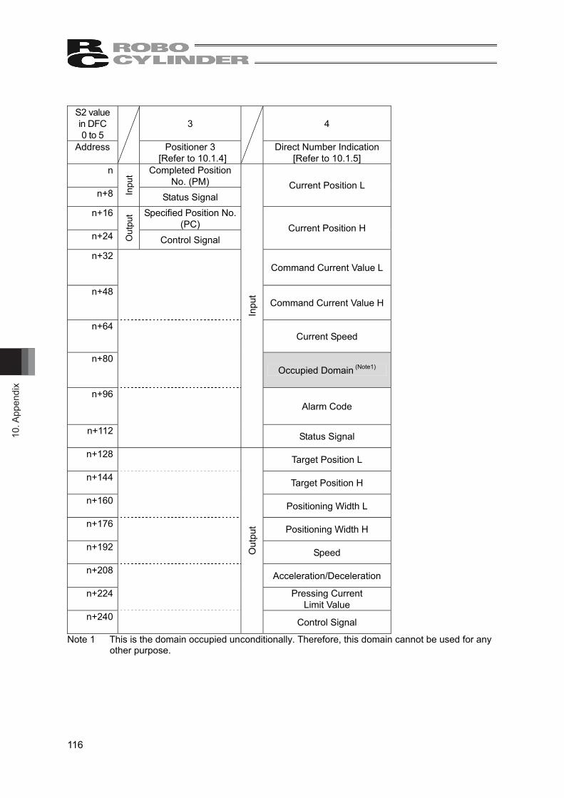
10. A
ppen
dix
116
S2 value in DFC 0 to 5
3 4
Address
Positioner 3 [Refer to 10.1.4]
Direct Number Indication
[Refer to 10.1.5] n Completed Position
No. (PM) n+8 In
put
Status Signal Current Position L
n+16 Specified Position No. (PC)
n+24 Out
put
Control Signal Current Position H
n+32 Command Current Value L
n+48 Command Current Value H
n+64 Current Speed
n+80 Occupied Domain (Note1)
n+96 Alarm Code
n+112
Inpu
t
Status Signal
n+128 Target Position L
n+144 Target Position H
n+160 Positioning Width L
n+176 Positioning Width H
n+192 Speed
n+208 Acceleration/Deceleration
n+224 Pressing Current
Limit Value n+240
Out
put
Control Signal
Note 1 This is the domain occupied unconditionally. Therefore, this domain cannot be used for any other purpose.
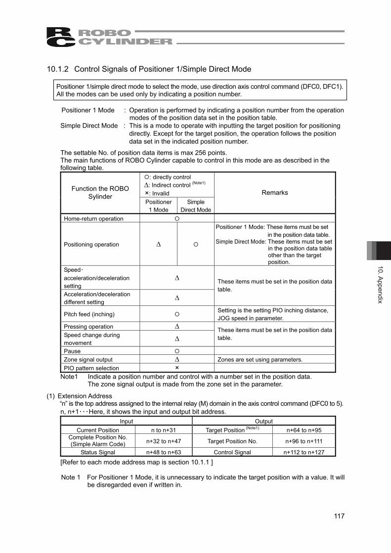
10. Appendix
117
10.1.2 Control Signals of Positioner 1/Simple Direct Mode
Positioner 1/simple direct mode to select the mode, use direction axis control command (DFC0, DFC1). All the modes can be used only by indicating a position number.
Positioner 1 Mode : Operation is performed by indicating a position number from the operation modes of the position data set in the position table. Simple Direct Mode : This is a mode to operate with inputting the target position for positioning
directly. Except for the target position, the operation follows the position data set in the indicated position number.
The settable No. of position data items is max 256 points. The main functions of ROBO Cylinder capable to control in this mode are as described in the following table.
: directly control ∆: Indirect control (Note1) ×: Invalid
Function the ROBO Sylinder
Positioner 1 Mode
Simple Direct Mode
Remarks
Home-return operation
Positioning operation ∆
Positioner 1 Mode: These items must be set in the position data table. Simple Direct Mode: These items must be set
in the position data table other than the target position.
Speed・acceleration/deceleration setting
∆
Acceleration/deceleration different setting
∆
These items must be set in the position data table.
Pitch feed (inching) Setting is the setting PIO inching distance, JOG speed in parameter.
Pressing operation ∆ Speed change during movement
∆ These items must be set in the position data table.
Pause Zone signal output ∆ Zones are set using parameters. PIO pattern selection ×
Note1 Indicate a position number and control with a number set in the position data. The zone signal output is made from the zone set in the parameter.
(1) Extension Address “n” is the top address assigned to the internal relay (M) domain in the axis control command (DFC0 to 5). n, n+1・・・Here, it shows the input and output bit address.
Input Output Current Position n to n+31 Target Position (Note1) n+64 to n+95
Complete Position No. (Simple Alarm Code) n+32 to n+47 Target Position No. n+96 to n+111
Status Signal n+48 to n+63 Control Signal n+112 to n+127 [Refer to each mode address map is section 10.1.1 ] Note 1 For Positioner 1 Mode, it is unnecessary to indicate the target position with a value. It will
be disregarded even if written in.

10. A
ppen
dix
118
(2) Input and Output Signal Assignment ● The control signals and status signals are ON/OFF signals in units of bit. ● For the target position number and current position number, 2-word (32-bit) binary data is
available and values from -999999 to +999999 (unit: 0.01mm) can be used. Negative numbers are to be dealt with two’s complement.
● For the indicated position number and complete position number, 1-word (16-bit) binary data is available and values from 0 to 255 can be used.
[Input] (“n” is the top address assigned to the internal relay (M) domain in the axis control command (DFC0 and 1). n, n+1・・・Here, it shows the input and output bit address.)
Address N to n+15 b15 b14 b13 b12 b11 b10 b9 b8 b7 b6 b5 b4 b3 b2 b1 b0 Current Position L (Lower word)
Address n+16 to n+31 b15 b14 b13 b12 b11 b10 b9 b8 b7 b6 b5 b4 b3 b2 b1 b0 Current Position H (Upper word)
(Note) If the current position is a negative value, it is indicated by a two’s complement.
Address n+32 to n+47 b15 b14 b13 b12 b11 b10 b9 b8 b7 b6 b5 b4 b3 b2 b1 b0 Complete Position No. – – – – – – – –
PM12
8
PM64
PM32
PM16
PM8
PM4
PM2
PM1
Address n+48 to n+63 b15 b14 b13 b12 b11 b10 b9 b8 b7 b6 b5 b4 b3 b2 b1 b0 Status Signal
EMG
S
CR
DY
ZON
E2
ZON
E1
– – –
MEN
D
ALM
L
–
PSFL
SV
ALM
MO
VE
HEN
D
PEN
D
Caution:• Set the position data in the range of the software stroke (0 to effective stroke length) of the actuator.
It is not necessary to have this setting done for Positioner 1 Mode.
Caution: Set the operational condition in advance with using a teaching tool such as PC software in the position number to be used. Selecting a position number with no setting conducted will generate the alarm code 0A2 “Position Data Error”.
1 word = 16 bit

10. Appendix
119
[Output] (“n” is the top address assigned to the internal relay (M) domain in the axis control command (DFC0 and 1). n, n+1・・・Here, it shows the input and output bit address.)
(Note) It will be ignored in Positioner 1 Mode even if the target positions (Target L and Target H) are set.
Address N+64 to n+79 b15 b14 b13 b12 b11 b10 b9 b8 b7 b6 b5 b4 b3 b2 b1 b0 Target Position L (Lower word)
Address n+80 to n+95 b15 b14 b13 b12 b11 b10 b9 b8 b7 b6 b5 b4 b3 b2 b1 b0 Target Position H (Upper word)
(Note) If the target position is a negative value, it is indicated by a two’s complement.
Address n+96 to n+111 b15 b14 b13 b12 b11 b10 b9 b8 b7 b6 b5 b4 b3 b2 b1 b0 Specified Position No. – – – – – – – –
PC12
8
PC64
PC32
PC16
PC8
PC4
PC2
PC1
Address n+112 to n+127 b15 b14 b13 b12 b11 b10 b9 b8 b7 b6 b5 b4 b3 b2 b1 b0 Control Signal
BKR
L
– – – – – –
JOG
+
JOG
-
–
JISL
SON
RES
STP
HO
ME
CST
R
1 word = 16 bit

10. A
ppen
dix
120
(3) Contents of input and output signals (ON=applicable bit is ”1”, OFF= applicable bit is “0”””)
Signal Type Bit Symbol Description Details
Current Position 32 bits -
32-bit signed integer indicating the current position Unit: 0.01mm (Example) If 10.23mm, input 000003FFH (1023 in
decimal number). (Note) Negative numbers are two’s implement.
10.2.21
Complete Position No.(Simple Alarm Code)
16 bits PM1 to PM128
16-bit intger. The positioning complete position number is output in a binary number once getting into the positioning width after moving to the target position in internal reray (M). In the case that the position movement has not been performed at all, or during the movement, “0” is input. Read it by turning PEND Signal ON after movement. The simple alarm code (refer to MSEP controller instruction manual chapter 6 Troubleshooting) is output while an alarm is issued (ALM of Status Signal is ON).
10.2.21
b15 EMGS In emergency stop condition ON 10.2.2
b14 CRDY This signal turns ON when the controller is standing by. 10.2.1
b13 ZONE2
“ON” for the current position within the zone 2 set range The zone range setting is necessary for the parameter.
b12 ZONE1
“ON” for the current position within the zone 1 set range The zone range setting is necessary for the parameter.
10.2.11
b11 b10 b9
- Cannot be used. -
b8 MEND
This signal turns ON at either of positioning complete, home return complete, pressing complete or pressing failure, and turns OFF at movement start. It is OFF before movement.
10.2.19
b7 ALML Light error alarm output It turns ON when a message level error is issued. 10.2.20
b6 - Cannot be used. -
b5 PSFL This signal turns ON when the actuator missed the load in push-motion operation. 10.2.18
b4 SV This signal turns ON when operation standby is complete (Servo is ON). 10.2.5
b3 ALM This signal is ON while an alarm is generated. 10.2.3 b2 MOVE This signal is ON while in movement. 10.2.8
b1 HEND This signal turns ON at home return complete and is kept unless the home position is lost due to a fact such as an alarm.
10.2.6
Inpu
t
Status Signal
b0 PEND This signal turns ON at positioning complete and is kept ON during a stop with the servo ON, but does not turn ON when pressing operation is failed.
10.2.9

10. Appendix
121
(ON=applicable bit is ”1”, OFF= applicable bit is “0”””) Signal Type Bit Symbol Description Details
Target Position
32 bit data -
32-bit signed integer indicating the current position Unit: 0.01mm Available range for Setting: -999999 to 999999 Set the target position with the value from the home position. 32-bit signed integer indicating the current position Unit: 0.01mm Available Unit: -999999 to 999999 (Exsample) If +25.40mm, 000009ECH (2540 in
decimal number) (Note) Negative numbers are two’s implement.
10.2.21
Specified Position
No.
16 bit data
PC1 to PC128
16-bit integer. Available range for Setting:: 0 to 255 To operate, it is necessary to have the position data that the operation conditions are already set in advance with a teaching tool such as the PC software. In this register, indicate the position number the data is input with a binary number. Indicating a value out of the range or operating with a position number with no setting conducted will generate the alarm code 0A2 “Position Data Error”.
10.2.21
b15 BKRL Brake release ON: Brake release, OFF: Brake activated 10.2.15
b14 b13 b12 b11 b10 b9
- Cannot be used. -
b8 JOG+ +Jog ON: Movement against home position, OFF: Stop
b7 JOG- -Jog ON: Movement toward home position, OFF: Stop
10.2.12
b6 - Cannot be used. -
b5 JISL Jog/inching switching ON: Inching, OFF: Jog 10.2.14
b4 SON Servo ON command ON: Servo ON, OFF: Servo OFF 10.2.5
b3 RES Reset A reset is performed when this signal turns ON. 10.2.4
b2 STP Pause ON: Pause, OFF: Pause release 10.2.10
b1 HOME
Home return Home-return command with this signal ON, command carried on till complete even if the signal is turned OFF on the way
10.2.6
Out
put
Control Signal
b0 CSTR
Positioning start Movement command executed with this signal ON, command carried on till complete even if the signal is turned OFF on the way
10.2.7
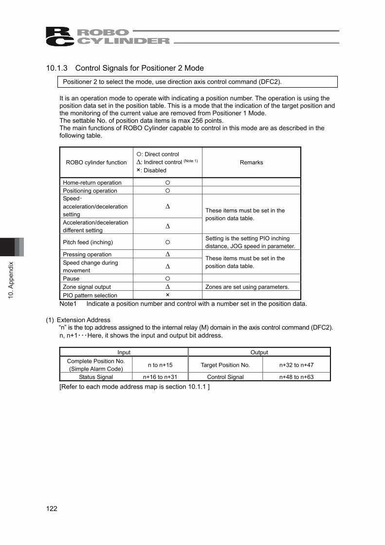
10. A
ppen
dix
122
10.1.3 Control Signals for Positioner 2 Mode Positioner 2 to select the mode, use direction axis control command (DFC2).
It is an operation mode to operate with indicating a position number. The operation is using the position data set in the position table. This is a mode that the indication of the target position and the monitoring of the current value are removed from Positioner 1 Mode. The settable No. of position data items is max 256 points. The main functions of ROBO Cylinder capable to control in this mode are as described in the following table.
ROBO cylinder function
: Direct control ∆: Indirect control (Note 1)
×: Disabled
Remarks
Home-return operation Positioning operation Speed・acceleration/deceleration setting
∆
Acceleration/deceleration different setting
∆
These items must be set in the position data table.
Pitch feed (inching) Setting is the setting PIO inching distance, JOG speed in parameter.
Pressing operation ∆
Speed change during movement
∆
These items must be set in the position data table.
Pause Zone signal output ∆ Zones are set using parameters. PIO pattern selection ×
Note1 Indicate a position number and control with a number set in the position data. (1) Extension Address
“n” is the top address assigned to the internal relay (M) domain in the axis control command (DFC2). n, n+1・・・Here, it shows the input and output bit address.
Input Output
Complete Position No. (Simple Alarm Code) n to n+15 Target Position No. n+32 to n+47
Status Signal n+16 to n+31 Control Signal n+48 to n+63 [Refer to each mode address map is section 10.1.1 ]

10. Appendix
123
(2) Input and Output Signal Assignment for each Axis The I/O signals for each axis consists of 2-word for each I/O bit register. ● The control signals and status signals are ON/OFF signals in units of bit. ● Binary data of 1-word (16-bit) for the specified position number and complete position number
and values from 0 to 255 can be used.
Caution: Set the operational condition in advance with using a teaching tool such as PC software in the position number to be used. Selecting a position number with no setting conducted will generate the alarm code 0A2 “Position Data Error”.
[Input] (“n” is the top address assigned to the internal relay (M) domain in the axis control command (DFC2). n, n+1・・・Here, it shows the input and output bit address.)
Address N to n+15 b15 b14 b13 b12 b11 b10 b9 b8 b7 b6 b5 b4 b3 b2 b1 b0
Complete Position No. – – – – – – – –
PM12
8
PM64
PM32
PM16
PM8
PM4
PM2
PM1
Address n+16 to n+31 b15 b14 b13 b12 b11 b10 b9 b8 b7 b6 b5 b4 b3 b2 b1 b0
Status Signal
EMG
S
CR
DY
ZON
E2
ZON
E1
– – –
MEN
D
ALM
L
–
PSFL
SV
ALM
MO
VE
HEN
D
PEN
D
[Output] (“n” is the top address assigned to the internal relay (M) domain in the axis control command (DFC2). n, n+1・・・Here, it shows the input and output bit address.)
Address n+32 to n+47 b15 b14 b13 b12 b11 b10 b9 b8 b7 b6 b5 b4 b3 b2 b1 b0
Specified Position No. – – – – – – – –
PC12
8
PC64
PC32
PC16
PC8
PC4
PC2
PC1
Address n+48 to n+63 b15 b14 b13 b12 b11 b10 b9 b8 b7 b6 b5 b4 b3 b2 b1 b0
Control Signal
BKR
L
– – – – – –
JOG
+
JOG
-
–
JISL
SON
RES
STP
HO
ME
CST
R
1 word = 16 bit
1 word = 16 bit
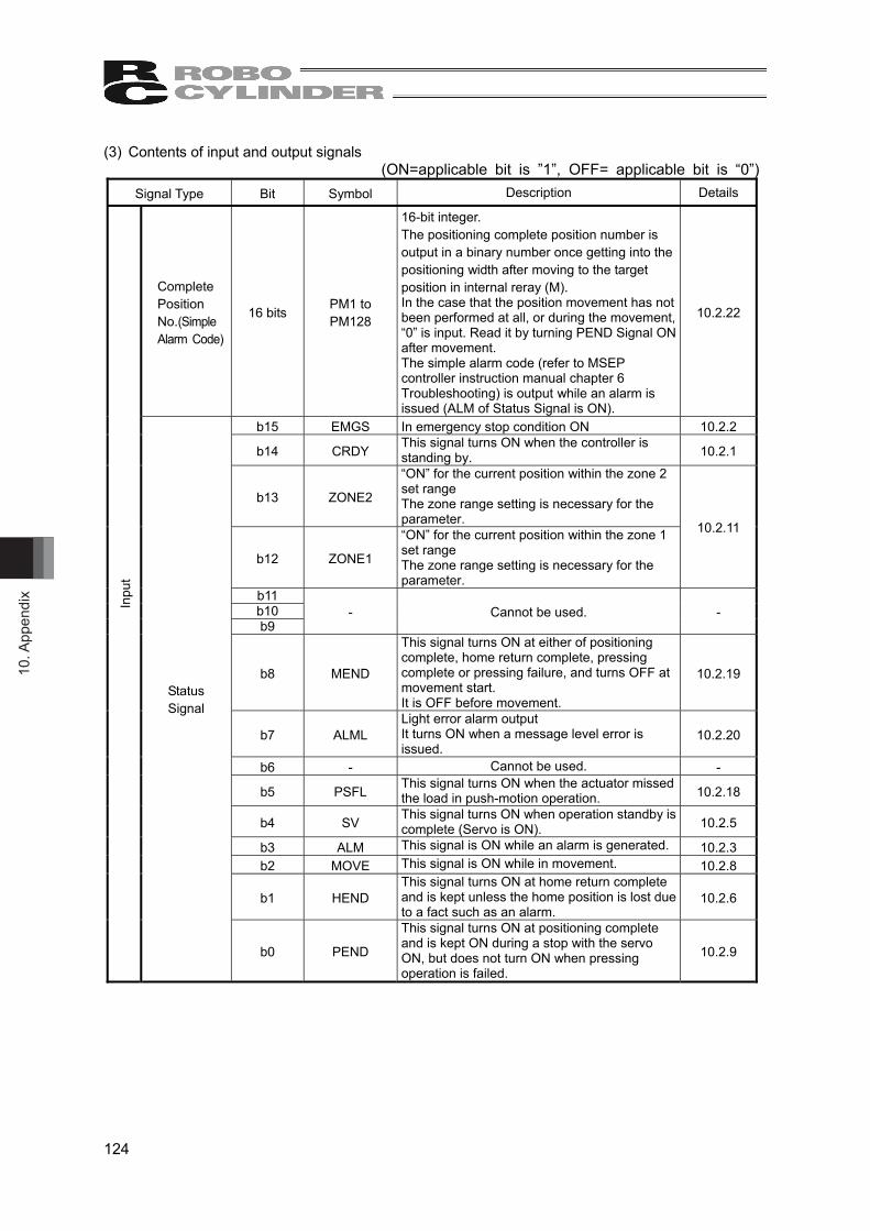
10. A
ppen
dix
124
(3) Contents of input and output signals (ON=applicable bit is ”1”, OFF= applicable bit is “0”)
Signal Type Bit Symbol Description Details
Complete Position No.(Simple Alarm Code)
16 bits PM1 to PM128
16-bit integer. The positioning complete position number is output in a binary number once getting into the positioning width after moving to the target position in internal reray (M). In the case that the position movement has not been performed at all, or during the movement, “0” is input. Read it by turning PEND Signal ON after movement. The simple alarm code (refer to MSEP controller instruction manual chapter 6 Troubleshooting) is output while an alarm is issued (ALM of Status Signal is ON).
10.2.22
b15 EMGS In emergency stop condition ON 10.2.2
b14 CRDY This signal turns ON when the controller is standing by. 10.2.1
b13 ZONE2
“ON” for the current position within the zone 2 set range The zone range setting is necessary for the parameter.
b12 ZONE1
“ON” for the current position within the zone 1 set range The zone range setting is necessary for the parameter.
10.2.11
b11 b10 b9
- Cannot be used. -
b8 MEND
This signal turns ON at either of positioning complete, home return complete, pressing complete or pressing failure, and turns OFF at movement start. It is OFF before movement.
10.2.19
b7 ALML Light error alarm output It turns ON when a message level error is issued.
10.2.20
b6 - Cannot be used. -
b5 PSFL This signal turns ON when the actuator missed the load in push-motion operation. 10.2.18
b4 SV This signal turns ON when operation standby is complete (Servo is ON). 10.2.5
b3 ALM This signal is ON while an alarm is generated. 10.2.3 b2 MOVE This signal is ON while in movement. 10.2.8
b1 HEND This signal turns ON at home return complete and is kept unless the home position is lost due to a fact such as an alarm.
10.2.6
Inpu
t
Status Signal
b0 PEND
This signal turns ON at positioning complete and is kept ON during a stop with the servo ON, but does not turn ON when pressing operation is failed.
10.2.9

10. Appendix
125
(ON=applicable bit is ”1”, OFF= applicable bit is “0”) Signal Type Bit Symbol Description Details
Specified Position
No.
16 bits data
PC1 to PC128
16-bit integer. Available range for Setting:: 0 to 255 To operate, it is necessary to have the position data that the operation conditions are already set in advance with a teaching tool such as the PC software. In this register, indicate the position number the data is input with a binary number. Indicating a value out of the range or operating with a position number with no setting conducted will generate the alarm code 0A2 “Position Data Error”.
10.2.22
b15 BKRL Brake release ON: Brake release, OFF: Brake activated 10.2.15
b14 b13 b12 b11 b10 b9
- Cannot be used. -
b8 JOG+ +Jog ON: Movement against home position, OFF: Stop
b7 JOG- -Jog ON: Movement toward home position, OFF: Stop
10.2.12
b6 - Cannot be used. -
b5 JISL Jog/inching switching ON: Inching, OFF: Jog 10.2.14
b4 SON Servo ON command ON: Servo ON, OFF: Servo OFF 10.2.5
b3 RES Reset A reset is performed when this signal turns ON. 10.2.4
b2 STP Pause ON: Pause, OFF: Pause release 10.2.10
b1 HOME
Home return Home-return command with this signal ON, command carried on till complete even if the signal is turned OFF on the way
10.2.6
Out
put
Control Signal
b0 CSTR
Positioning start Movement command executed with this signal ON, command carried on till complete even if the signal is turned OFF on the way
10.2.7
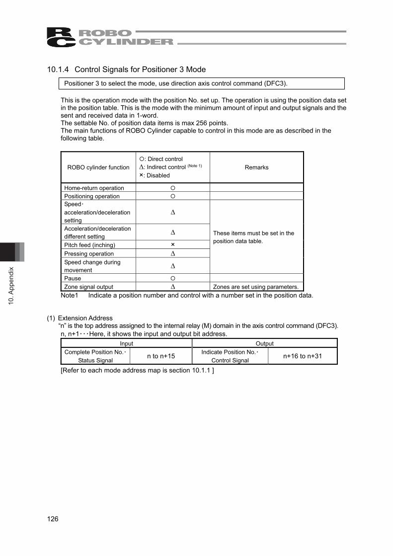
10. A
ppen
dix
126
10.1.4 Control Signals for Positioner 3 Mode Positioner 3 to select the mode, use direction axis control command (DFC3).
This is the operation mode with the position No. set up. The operation is using the position data set in the position table. This is the mode with the minimum amount of input and output signals and the sent and received data in 1-word. The settable No. of position data items is max 256 points. The main functions of ROBO Cylinder capable to control in this mode are as described in the following table.
ROBO cylinder function
: Direct control ∆: Indirect control (Note 1)
×: Disabled
Remarks
Home-return operation Positioning operation Speed・acceleration/deceleration setting
∆
Acceleration/deceleration different setting
∆
Pitch feed (inching) ×
Pressing operation ∆ Speed change during movement
∆
These items must be set in the position data table.
Pause Zone signal output ∆ Zones are set using parameters.
Note1 Indicate a position number and control with a number set in the position data. (1) Extension Address
“n” is the top address assigned to the internal relay (M) domain in the axis control command (DFC3). n, n+1・・・Here, it shows the input and output bit address.
Input Output Complete Position No.・
Status Signal n to n+15 Indicate Position No.・ Control Signal n+16 to n+31
[Refer to each mode address map is section 10.1.1 ]

10. Appendix
127
(2) Input and Output Signal Assignment for each Axis ● The control signals and status signals are ON/OFF signals in units of bit. ● Binary data of 8-bit for the specified position number and complete position number and values
from 0 to 255 can be used.
Caution: Set the operational condition in advance with using a teaching tool such as PC software in the position number to be used. Selecting a position number with no setting conducted will generate the alarm code 0A2 “Position Data Error”.
[Input] (“n” is the top address assigned to the internal relay (M) domain in the axis control command (DFC3). n, n+1・・・Here, it shows the input and output bit address.)
Address N to n+15 b15 b14 b13 b12 b11 b10 b9 b8 b7 b6 b5 b4 b3 b2 b1 b0 Complete Position No./Status Signal EM
GS
ZON
E1
PSFL
SV
ALM
MO
VE
HEN
D
PEN
D
PM12
8
PM64
PM32
PM16
PM8
PM4
PM2
PM1
[Output] (“n” is the top address assigned to the internal relay (M) domain in the axis control command (DFC3). n, n+1・・・Here, it shows the input and output bit address.)
Address n+16 to n+31 b15 b14 b13 b12 b11 b10 b9 b8 b7 b6 b5 b4 b3 b2 b1 b0 Control Signal/ Specified Position No. BK
RL
-
-
SON
RES
STP
HO
ME
CST
R
PC12
8
PC64
PC32
PC16
PC8
PC4
PC2
PC1
1 word = 16 bit
Control Signal Indication Position No.
Status Signal Complete Position No.
1 word = 16 bit

10. A
ppen
dix
128
(3) Contents of input and output signals (ON=applicable bit is ”1”, OFF= applicable bit is “0”)
Signal Type Bit Symbol Description Details
b15 EMGS This signal turns ON during an emergency stop 10.2.2
b14 ZONE1
“ON” for the current position within the zone 1 set range The zone range setting is necessary for the parameter.
10.2.11
b13 PSFL This signal turns ON when the actuator missed the load in push-motion operation. 10.2.18
b12 SV This signal turns ON when operation standby is complete (Servo is ON). 10.2.5
b11 ALM This signal is ON while an alarm is generated. 10.2.3 b10 MOVE This signal is ON while in movement. 10.2.8
b9 HEND This signal turns ON at home return complete and is kept unless the home position is lost due to a fact such as an alarm.
10.2.6
b8 PEND This signal turns ON at positioning complete and is kept ON during a stop with the servo ON, but does not turn ON when pressing operation is failed.
10.2.9
b7 PM128 b6 PM64 b5 PM32 b4 PM16 b3 PM8 b2 PM4 b1 PM2
Inpu
t
Complete Position
No. ・
Status Signal
b0 PM1
Complete position No. 8-bits binary data Available range for Setting:: 0 to 255 To operate, it is necessary to have the position data that the operation conditions are already set in advance with a teaching tool such as the PC software. In this register, indicate the position number the data is input with a binary number. Indicating a value out of the range or operating with a position number with no setting conducted will generate the alarm code 0A2 “Position Data Error”.
10.2.22
b15 BKRL Brake compulsory release ON: Brake compulsory release, OFF: Effective brak
10.2.15
b14 b13
- Cannot be used. -
b12 SON Servo ON directive ON: Servo ON, OFF: Servo OFF 10.2.5
b11 RES Reset A reset is performed when this signal turns ON. 10.2.4
b10 STP Pause ON: Pause, OFF: Pause release 10.2.10
b9 HOME
Home return Home-return command with this signal ON, command carried on till complete even if the signal is turned OFF on the way
10.2.6
b8 CSTR
Positioning start Movement command executed with this signal ON, command carried on till complete even if the signal is turned OFF on the way
10.2.7
b7 PC7 b6 PC6 b5 PC5 b4 PC5 b3 PC4 b2 PC3 b1 PC2
Out
put
Indicated Position
No. ・
Control Signal
b0 PC1
Indicated Position No. 8-bits binary data Available range for Setting:: 0 to 255 To operate, it is necessary to have the position data that the operation conditions are already set in advance with a teaching tool such as the PC software. In this register, indicate the position number the data is input with a binary number. Indicating a value out of the range or operating with a position number with no setting conducted will generate the alarm code 0A2 “Position Data Error”.
10.2.22

10. Appendix
129
10.1.5 Control Signals for Direct Indication Mode. Direct indication mode to select the mode, use direction axis control command (DFC4). It is the way to operate by indicating values directly for the target position, positioning band, velocity, acceleration and pressing current. Set each value in the internal relay (M) indicated in the axis control command (DFC4). Establish the setting in the parameter when to use the zone signal. The main functions of ROBO Cylinder capable to control in this mode are as described in the following table.
ROBO cylinder function
: Direct control ∆: Indirect control (Note 1)
×: Disabled
Remarks
Home-return operation Positioning operation Speed・acceleration/deceleration setting
Acceleration/deceleration different setting
× Same value as acceleration・deceleration.
Pitch feed (inching)
Pressing operation
Selection can be made from the pressing method same as CON type such as PCON and that same as SEP type such as PSEP.
Speed change during movement
Pause Zone signal output ∆ Zones are set using parameters. PIO pattern selection ×
Note 1 The zone signal output is made from the zone set in the parameter.
(1) Extension Address
“n” is the top address assigned to the internal relay (M) domain in the axis control command (DFC4). n, n+1・・・Here, it shows the input and output bit address.
Input Output Current Position n to n+31 Target Position n+128 to n+159
Command Current Value n+32 to n+63 Positioning Width n+160 to n+191 Current Speed n+64 to n+79 Speed n+192 to n+207
Cannot be used n+80 to n+95 Acceleration/Deceleration n+208 to n+223 Alarm Code n+96 to n+111 Pressing Current Limit Value n+224 to n+239
Status Signal n+112 to n+127 Control Signal n+240 to n+255 [Refer to each mode address map is section 10.1.1 ]
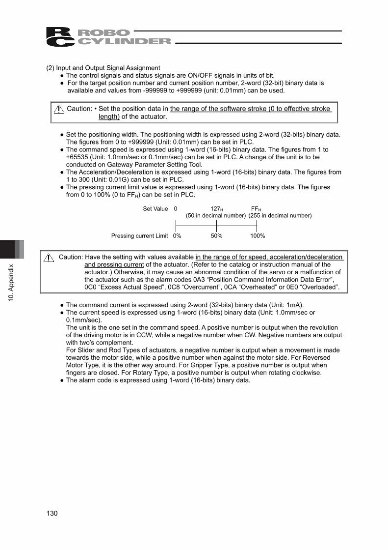
10. A
ppen
dix
130
(2) Input and Output Signal Assignment ● The control signals and status signals are ON/OFF signals in units of bit. ● For the target position number and current position number, 2-word (32-bit) binary data is
available and values from -999999 to +999999 (unit: 0.01mm) can be used.
Caution: • Set the position data in the range of the software stroke (0 to effective stroke length) of the actuator.
● Set the positioning width. The positioning width is expressed using 2-word (32-bits) binary data.
The figures from 0 to +999999 (Unit: 0.01mm) can be set in PLC. ● The command speed is expressed using 1-word (16-bits) binary data. The figures from 1 to
+65535 (Unit: 1.0mm/sec or 0.1mm/sec) can be set in PLC. A change of the unit is to be conducted on Gateway Parameter Setting Tool.
● The Acceleration/Deceleration is expressed using 1-word (16-bits) binary data. The figures from 1 to 300 (Unit: 0.01G) can be set in PLC.
● The pressing current limit value is expressed using 1-word (16-bits) binary data. The figures from 0 to 100% (0 to FFH) can be set in PLC.
Caution: Have the setting with values available in the range of for speed, acceleration/deceleration
and pressing current of the actuator. (Refer to the catalog or instruction manual of the actuator.) Otherwise, it may cause an abnormal condition of the servo or a malfunction of the actuator such as the alarm codes 0A3 “Position Command Information Data Error”, 0C0 “Excess Actual Speed”, 0C8 “Overcurrent”, 0CA “Overheated” or 0E0 “Overloaded”.
● The command current is expressed using 2-word (32-bits) binary data (Unit: 1mA). ● The current speed is expressed using 1-word (16-bits) binary data (Unit: 1.0mm/sec or
0.1mm/sec). The unit is the one set in the command speed. A positive number is output when the revolution of the driving motor is in CCW, while a negative number when CW. Negative numbers are output with two’s complement. For Slider and Rod Types of actuators, a negative number is output when a movement is made towards the motor side, while a positive number when against the motor side. For Reversed Motor Type, it is the other way around. For Gripper Type, a positive number is output when fingers are closed. For Rotary Type, a positive number is output when rotating clockwise.
● The alarm code is expressed using 1-word (16-bits) binary data.
Set Value 0 127H FFH (50 in decimal number) (255 in decimal number) Pressing current Limit 0% 50% 100%

10. Appendix
131
[Input] (“n” is the top address assigned to the internal relay (M) domain in the axis control command (DFC4). n, n+1・・・Here, it shows the input and output bit address.)
Address N to n+15 b15 b14 b13 b12 b11 b10 b9 b8 b7 b6 b5 b4 b3 b2 b1 b0 Current Position L (Lower word)
Address n+16 to n+31 b15 b14 b13 b12 b11 b10 b9 b8 b7 b6 b5 b4 b3 b2 b1 b0 Current Position H (Upper word)
(Note) If the target position is a negative value, it is output by a two’s complement.
Address n+32 to n+47 b15 b14 b13 b12 b11 b10 b9 b8 b7 b6 b5 b4 b3 b2 b1 b0 Command Current Value L (Lower word) 32
,768
16,3
84
8,19
2
4,09
6
2,04
8
1,02
4
512
256
128
64
32
16
8 4 2 1
Address n+48 to n+63 b15 b14 b13 b12 b11 b10 b9 b8 b7 b6 b5 b4 b3 b2 b1 b0 Command Current Value H (Upper word)
– – – – – – – – – – – –
524,
288
262,
144
131,
072
65,5
36
Address n+64~n+79 b15 b14 b13 b12 b11 b10 b9 b8 b7 b6 b5 b4 b3 b2 b1 b0 Current Speed
(Note) If the negative value, it is indicated by a two’s complement.
Address n+80 to n+95 b15 b14 b13 b12 b11 b10 b9 b8 b7 b6 b5 b4 b3 b2 b1 b0 Can not be used
Address n+96~n+111 b15 b14 b13 b12 b11 b10 b9 b8 b7 b6 b5 b4 b3 b2 b1 b0 Alarm Code
Address n+112 to n+127 b15 b14 b13 b12 b11 b10 b9 b8 b7 b6 b5 b4 b3 b2 b1 b0 Status Signal
EMG
S
CR
DY
ZON
E2
ZON
E1
– – –
MEN
D
ALM
L
–
PSFL
SV
ALM
MO
VE
HEN
D
PEN
D
1 word = 16 bit

10. A
ppen
dix
132
[Output] (“n” is the top address assigned to the internal relay (M) domain in the axis control command (DFC4). n, n+1・・・Here, it shows the input and output bit address.)
Address n+128 to n+143 b15 b14 b13 b12 b11 b10 b9 b8 b7 b6 b5 b4 b3 b2 b1 b0 Target Position L (Lower word)
Address n+144 to n+159 b15 b14 b13 b12 b11 b10 b9 b8 b7 b6 b5 b4 b3 b2 b1 b0 Target Position H (Lower word)
(Note) If the target position is a negative value, it is input by a two’s complement.
Address n+160 to n+175 b15 b14 b13 b12 b11 b10 b9 b8 b7 b6 b5 b4 b3 b2 b1 b0 Positioning Width L (Lower word)
32,7
68
16,3
84
8,19
2
4,09
6
2,04
8
1,02
4
512
256
128
64
32
16
8 4 2 1
Address n+176 to n+191 b15 b14 b13 b12 b11 b10 b9 b8 b7 b6 b5 b4 b3 b2 b1 b0 Positioning Width H (Upper word) – – – – – – – – – – – –
524,
288
262,
144
131,
072
65,5
36
Address n+192 to n+207 b15 b14 b13 b12 b11 b10 b9 b8 b7 b6 b5 b4 b3 b2 b1 b0 Speed
32,7
68
16,3
84
8,19
2
4,09
6
2,04
8
1,02
4
512
256
128
64
32
16
8 4 2 1
Address n+208 to n+223 b15 b14 b13 b12 b11 b10 b9 b8 b7 b6 b5 b4 b3 b2 b1 b0 Acceleration/ Deceleration
– – – – – – – 256
128
64
32
16
8 4 2 1
Address n+224 to n+239 b15 b14 b13 b12 b11 b10 b9 b8 b7 b6 b5 b4 b3 b2 b1 b0 Pressing Current Limit Value
– – – – – – – 256
128
64
32
16
8 4 2 1
Address n+240 to n+255 b15 b14 b13 b12 b11 b10 b9 b8 b7 b6 b5 b4 b3 b2 b1 b0 Control Signal
BKR
L
INC
DIR
PUSH
– – –
JOG
+
JOG
-
–
JISL
SON
RES
STP
HO
ME
CST
R
1 word = 16 bit

10. Appendix
133
(3) Contents of input and output signals (ON=applicable bit is ”1”, OFF= applicable bit is “0”)
Signal Type Bit Symbol Description Details
Current Position
32 bits data -
32-bit signed integer indicating the current position unit: 0.01mm (Example) If 10.23mm, input 000003FFH (1023 in decimal
number). (Note) Negative numbers are two’s implement.
10.2.23
Command Current Value
32 bits data -
32-bit integer The electrical current presently specified by a command is indicated. The setting unit is mA. Output in hexadecimal numbers. (Example) Reading: 000003FFH = 1023 (in decimal
number) = 1023mA
10.2.23
Current Speed
16 bits data -
16-bit integer The current speed is indicated. Unit: 1.0mm/sec or 0.1mm/sec. A change of the unit is to be conducted on Gateway Parameter Setting Tool. (Example) Reading: 03FFH = 1023 (in decimal number) = 1023mm/sec (Note) Negative numbers are two’s implement.
10.2.23
Alarm Code
16 bits data -
16-bit integer The alarm code (refer to MSEP controller instruction manual chapter 6 Troubleshooting) is output while an alarm is issued (ALM of Status Signal is ON).
10.2.23
b15 EMGS This signal turns ON during an emergency stop 10.2.2 b14 CRDY This signal turns ON when the controller is standing by. 10.2.1
b13 ZONE2 “ON” for the current position within the zone 2 set range The zone range setting is necessary for the parameter.
b12 ZONE1 “ON” for the current position within the zone 1 set range The zone range setting is necessary for the parameter.
10.2.11
b11 b10 b9
- Cannot be used. -
b8 MEND
This signal turns ON at either of positioning complete, home return complete, pressing complete or pressing failure, and turns OFF at movement start. It is OFF before movement.
10.2.19
b7 ALML Light error alarm output It turns ON when a message level error is issued. 10.2.20
b6 - Cannot be used. -
b5 PSFL This signal turns ON when the actuator missed the load in push-motion operation. 10.2.18
b4 SV This signal turns ON when operation standby is complete (Servo is ON). 10.2.5
b3 ALM This signal is ON while an alarm is generated. 10.2.3 b2 MOVE This signal is ON while in movement. 10.2.8
b1 HEND This signal turns ON at home return complete and is kept unless the home position is lost due to a fact such as an alarm.
10.2.6
Inpu
t
Status Signal
b0 PEND This signal turns ON at positioning complete and is kept ON during a stop with the servo ON, but does not turn ON when pressing operation is failed.
10.2.9

10. A
ppen
dix
134
(ON=applicable bit is ”1”, OFF= applicable bit is “0”) Signal Type Bit Symbol Description Details
Target Position
32 bits data -
32-bit signed integer indicating the current position Unit: 0.01mm Available range for Setting: -999999 to 999999 Set the target position with the value from the home position. (Example) If +25.40mm, input 000009ECH (2540 in
decimal number). (Note) Input the negative value using a compliment of 2.
10.2.23
Positioning Width
32 bits data -
32-bit integer Unit: 0.01mm Available range for Setting: 0 to 999999 (Example) If 25.40mm, input 000009ECH (2540 in
decimal number). This register value has two meanings depending on the operation type. 1) Positioning operation Range for positioning
complete against the target position 2) Pressing operation Pressing width (Pressing
operation distance) A pressing operation is performed when PUSH Signal in the control signals is ON.
10.2.23
Speed 16 bits data -
16-bit integer Unit: 1.0mm/sec or 0.1mm/sec (It is set to 1.0mm/sec in the initial setting.) A change of the unit is to be conducted on Gateway Parameter Setting Tool. Available range for Setting: 1 to 65535 Specify the speed at which to move the actuator. (Example) In case of 0.1mm/sec unit, 254.0mm/sec,
input 09ECH (2540 in decimal number). It may cause an alarm or a malfunction if executing a movement command with 0 or a value more than the maximum speed of the actuator.
10.2. 23
Acceleration/ Deceleration
16 bit data -
16-bit integer Unit: 0.01G Available range for Setting: 1 to 300 Specify the acceleration/deceleration at which to move the actuator. The acceleration and deceleration will be the same value. (Example) If 0.30G, input 001EH (30 in decimal number).
It may cause an alarm or a malfunction if executing a movement command with 0 or a value exceeding the maximum acceleration/deceleration of the actuator.
10.2.23
Out
put
Pressing Current Limit
Value 16 bits data -
16-bit integer Unit: % Available range for Setting: 0 to FFH 7FH=50%, FFH=100% Indicate the current value for pressing operation. (Example) When setting to 50%, indicate FFH * 50% =
255 * 50% = 127 (in decimal number) = 007FH.
The pressing range available for indication differs depending on the actuator (Refer to the catalogue or instruction manual for the actuator). It may cause an alarm or a malfunction if executing a movement command with a value more than the maximum pressing current.
10.2.23

10. Appendix
135
Signal Type Bit Symbol Description Details
b15 BKRL Brake release ON: Brake release, OFF: Brake activated 10.2.15
b14 INC Absolute position commands are issued when this signal is OFF, and incremental position commands are issued when the signal is ON.
10.2.13
b13 DIR
Push direction specification ON: Movement against home position, OFF: Movement toward home position (Note) This signal is effective when the pressing method
of CON type is selected.
10.2.17
b12 PUSH Push-motion specification ON: Pressing operation, OFF: Positioning operation 10.2.16
b11 b10 b9
- Cannot be used. -
b8 JOG+ +Jog ON: Movement against home position, OFF: Stop
b7 JOG- -Jog ON: Movement toward home position, OFF: Stop
10.2.12
b6 - Cannot be used. -
b5 JISL Jog/inching switching ON: Inching, OFF: Jog 10.2.14
b4 SON Servo ON command ON: Servo ON, OFF: Servo OFF 10.2.5
b3 RES Reset A reset is performed when this signal turns ON. 10.2.4
b2 STP Pause ON: Pause, OFF: Pause release 10.2.10
b1 HOME
Home return Home-return command with this signal ON, command carried on till complete even if the signal is turned OFF on the way
10.2.6
Out
put
Control Signal
b0 CSTR
Positioning start Movement command executed with this signal ON, command carried on till complete even if the signal is turned OFF on the way
10.2.7

10. A
ppen
dix
136
10.2 I/O Signal Control and Functions of Axes Control Command (DFC0 to 5)
ON=applicable bit is ”1”, OFF= applicable bit is “0” 10.2.1 Controller Ready (CRDY) Input
When the controller can control the system after the power injection, it is turned “ON”. ■ Function Regardless of the alarm or servo conditions, when the controller initialization is completed normally after the power injection and the controller can control the system, it is turned “ON”. Even in the alarm condition, when the controller can control the system, it is turned “ON”.
10.2.2 Emergency Stop (EMGS) Input
When the controller is stopped in an emergency, it is turned “ON”. ■ Function When the controller is stopped in an emergency (motor driving power is cut off), it is turned “ON”. When the emergency stop status is cleared, it is turned “OFF”.
10.2.3 Alarm (ALM) Input
When any error is detected using the controller protection circuit (function), it is turned “ON”. ■ Function When any error is detected and the protection circuit (function) is activated, this signal is turned “ON”. When the cause of the alarm is eliminated and the reset (RES) signal is turned “ON”, the alarm is turned “OFF” in the case that it is the alarm with the operation cancellation level. (In the case of the alarm with the cold start level, re-injection of the power is required.)
10.2.4 Reset (RES) Output
This signal has two functions. It can reset the controller alarm and cancel the reminder for planned movements during pause conditions. ■ Function
1) When this signal is turned ON from OFF condition after eliminating the cause of the alarm during the alarm output, the alarm (ALM) signal can be reset. (In the case of the alarm with the cold start level, re-injection of the power is required.)
2) When this signal is turned ON from OFF condition during the pause condition, the reminder of the planned movement left can be cancelled.

10. Appendix
137
10.2.5 Servo ON Command (SON) Output Operation Ready (SV) Input
When the SON signal is turned ON, the servo will turn ON. When the servo-motor is turned ON, the Status Indicator LED (SYS*) on the front surface of the MSEP controller illuminates in green. The “SV” signal is synchronized with this LED. ■ Function Using the “SON” signal, the turning ON/OFF of the controller is available. While the “SV” signal is ON, the controller's servo-motor is turned “ON” and the operation becomes available. The relationship between the “SON” signal and “SV” signal is as follows.
SON(Output)
SV(Input)
10.2.6 Home Return (HOME) Output Home Return Complection (HEND) Input
When the “HOME” signal is turned “ON”, this command is processed at the startup (ON edge), and the homing operation is performed automatically. When the data home return is completed, the HEND signal is turned “ON”. Once the “HEND” signal is turned “ON”, it can not be turned “OFF” until the power is turned “OFF” or the “HOME” signal is input again. Even after the completion of the homing operation, when the “HOME” signal is turned “ON”, the homing operation can be performed.
HOME(Output)
(Input)
(Input)
(Input)
HEND
PEND
MOVE
Actuator operation
Mechanical end Stop at the Home Position
Caution: In the positioner 1/simple direct mode, positioner 2 mode, positioner 3 mode, when the positioning command is issued without performing the homing operation after the power injection, the positioning is performed after the automatic homing operation. Exercise caution that in the direct numeric specification mode, issuing a positioning command to a given position following the power on, without performing a home return first, will generate an alarm “Error Code 83: ALARM HOME ABS (absolute position move command when home return is not yet completed)” (operation-reset alarm).

10. A
ppen
dix
138
10.2.7 Positioning Start (CSTR) Output This signal is processed at the startup (ON edge) and the positioning is performed to the target position with the specified position No. or set using the internal relay (M) domain. In the positioner 1/simple direct mode, positioner 2 mode, positioner 3 mode, If a movement command is issued when the first home return is not yet completed after the power is turned ON (HEND signal OFF), home return will be performed automatically to establish the coordinates first, after which the actuator will move to the target position. Turn “OFF” this signal after confirming that the Positioning Completion Signal (PEND) signal has been turned “OFF”. Exercise caution that in the direct numeric specification mode, issuing a positioning command to a given position following the power on, without performing a home return first, will generate an alarm “Error Code 83: ALARM HOME ABS (absolute position move command when home return is not yet completed)” (operation-reset alarm).
Target position
(Output)
(Output)
(Input)
CSTR
PEND
10.2.8 Moving Signal (MOVE) Input
This signal is turned ON while the actuator’s slider or rod is moving. (including the pressing or jog operation after the homing operation.) After the completion of the positioning, homing or pressing operation, or during the pause condition, this signal is turned “OFF”.
10.2.9 Positioning Complection Signal (PEND) Input
This signal is turned “ON” when the actuator is moved to the target position and reaches the positioning width and the pressing is completed.
Speed
Movement distance
Target position
Positioning width
Time
Timing at which the position complete signal turns ON
When the servo-motor is turned ON from OFF condition, the positioning is performed with the position set as the target position. Accordingly, this signal is turned “ON” and after that, when the positioning operation is started with the home return (HOME) signal and positioning start (CSTR) signal, this signal is turned “OFF”.
Caution: When the servo-motor is turned OFF or stopped in an emergency while the actuator is stopped at the target position, the PEND signal is turned “OFF” temporarily. Then, when the servo-motor is turned “ON” and the actuator is within the positioning width, the PEND signal is turned “ON” again. When the positioning is completed with the CSTR signal turned “ON”, the PEND signal is not turned “ON”.
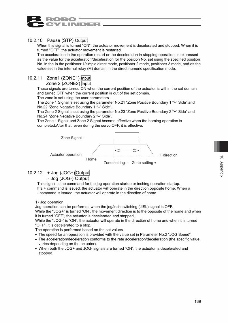
10. Appendix
139
10.2.10 Pause (STP) Output When this signal is turned “ON”, the actuator movement is decelerated and stopped. When it is turned “OFF”, the actuator movement is restarted. The acceleration in the operation restart or the deceleration in stopping operation, is expressed as the value for the acceleration/deceleration for the position No. set using the specified position No. in the In the positioner 1/simple direct mode, positioner 2 mode, positioner 3 mode, and as the value set in the internal relay (M) domain in the direct numeric specification mode.
10.2.11 Zone1 (ZONE1) Input Zone 2 (ZONE2) Input
These signals are turned ON when the current position of the actuator is within the set domain and turned OFF when the current position is out of the set domain. The zone is set using the user parameters. The Zone 1 Signal is set using the parameter No.21 “Zone Positive Boundary 1 “+” Side” and No.22 “Zone Negative Boundary 1 “–” Side”. The Zone 2 Signal is set using the parameter No.23 “Zone Positive Boundary 2 “+” Side” and No.24 “Zone Negative Boundary 2 “–” Side”. The Zone 1 Signal and Zone 2 Signal become effective when the homing operation is completed.After that, even during the servo OFF, it is effective.
Zone Signal
Actuator operationHome
Zone setting - Zone setting +
+ direction
10.2.12 + Jog (JOG+) Output - Jog (JOG-) Output
This signal is the command for the jog operation startup or inching operation startup. If a + command is issued, the actuator will operate in the direction opposite home. When a - command is issued, the actuator will operate in the direction of home.
1) Jog operation Jog operation can be performed when the jog/inch switching (JISL) signal is OFF. While the “JOG+” is turned “ON”, the movement direction is to the opposite of the home and when it is turned “OFF”, the actuator is decelerated and stopped. While the “JOG-” is “ON”, the actuator will operate in the direction of home and when it is turned “OFF”, it is decelerated to a stop. The operation is performed based on the set values. The speed for an operation is provided with the value set in Parameter No.2 “JOG Speed”. The acceleration/deceleration conforms to the rate acceleration/deceleration (the specific value
varies depending on the actuator). When both the JOG+ and JOG- signals are turned “ON”, the actuator is decelerated and
stopped.

10. A
ppen
dix
140
2) Inching operation The inching operation is available while the JISL signal is turned “ON”. Once it is turned “ON”, the actuator is moved as much as the inching distance. When the JOG+ is turned “ON”, the movement is to the opposite of the home and when the JOG- is turned “ON”, the movement is to the home. The operation is performed based on the set values. The speed for an operation is provided with the value set in Parameter No.2 “JOG Speed”. The movement distance for an operation is provided with the value set in Parameter No.25 “PIO
Inching Distance”. The acceleration/deceleration conforms to the rate acceleration/deceleration (the specific value
varies depending on the actuator).
During the normal operation, even when the “+” Jog Signal or “-” Jog Signal is turned “ON”, the normal operation is continued. (The Jog signal is ignored.) In the pause condition, even when the “+” Jog Signal or “-” Jog Signal is turned “ON”, the actuator is not moved.
10.2.13 Incremental Command (INC) Output
If this signal is ON and a movement command is executed, the actuator moves for the distance set in the target position internal relay (M) domain from the current position.
10.2.14 Jog/inching Switching (JISL) Output
This signal changes over the jog operation and the inching operation. JISL = OFF : Jog operation JISL = ON : Inching operation When the JISL signal is turned “ON” (for inching operation) during the jog operation, the actuator is decelerated and performs the inching operation. When the JISL signal is turned “OFF” (jog) while the actuator is moving by inching, the actuator will complete the movement and then switch to the jog function.
Jog operation Inching operation JISL OFF ON
Speed MSEP Controller: Parameter No.2, “Jog speed”
MSEP Controller: Parameter No.2, “Jog speed”
Movement distance - MSEP Controller: Parameter No.25, “PIO Inch distance”
Acceleration/ deceleration Rated value (The specific value varies depending on the actuator.)
Rated value (The specific value varies depending on the actuator.)
Operation When the JOG +/JOG – signal is ON. Upon detection of the leading (ON edge) of the JOG +/JOG – signal.
10.2.15 Brake Release (BKRL) Output
Turning this signal “ON” can release the brake forcibly.
Caution: Because the software stroke limit is disabled before the homing operation, the actuator might run against the mechanism end. Take the greatest care.

10. Appendix
141
10.2.16 Push-motion Specification (PUSH) Output When the movement command signal is output after this signal is turned ON, the pressing operation is performed. When this signal is set to “OFF”, the normal positioning operation is performed. In case of MSEP controller, direct indication mode, the same pressing type as CON related models such as PCON controller or the same pressing type as SEP related models such as PSEP controller can be selected for the pressing type in gateway parameter setting tool.
[Pressing Operation CON Method] After reaching the target position (Note 1) from the current position, the actuator moves with the pressing speed for the distance set as the pressing band width. The positioning complete signal (PEND) turns ON if the work piece hits and pressing is judged as completed while in the pressing operation. (Note 1) In direct indication mode, it is the value input in the target position internal relay (M)
domain. (Note 2) It is a function limited for direct indication mode. Select SEP system and CON system
in the special parameter setting in gateway parameter setting tool.
Speed
Movement distance
Target positionPressing width (Max. pressing level)
Position where the actuator is pushed against the work and the pressing completion is judged so the positioning completion signal is turned “ON”
↓
[Pressing Operation SEP Method]
The pressing operation is performed with the start position set at the point in front of the target position (Note 1) for the width of the positioning width (for direct indication mode), or the point set in the pressing width (for positioner 1/simplified direct value mode). The positioning complete signal (PEND) turns ON if the work piece hits and pressing is judged as completed while in the pressing operation. (Note 1) The value is that set as the position in the position data for positioner 1/simple direct
mode, positioner 2 mode, positioner 3 mode, and that input in the target position internal relay (M) domain for simple direct and direct indication modes.
(Note 2) Pulling operation cannot be performed.
Current position
↓
Pressing start position
Speed
Target position
Positioning width
Position where the actuator is pushed against the work and the pressing completion is judged so the positioning completion signal is turned “ON”

10. A
ppen
dix
142
10.2.17 Push Direction Specification (DIR) Output This signal specifies the pressing direction. When this signal is turned “OFF”, the pressing operation is performed to the direction of the value determined by adding the positioning width to the target position. Pressing operation starts towards the position where the positioning width is added to the target position if this signal is turned ON. When the normal positioning operation or SEP method pressing operation is selected, this signal is ineffective.
Speed
Movement distance
Positioning width Positioning width Positioning width
DIR = OFF DIR = ONTarget position 10.2.18 Pressing and a Miss (PSFL) Input
In the case that the pressing operation was performed, and the actuator moved the travel distance set in the controller position table positioning width or set using the PLC’s positioning width internal relay (M) domain, but it was not pushed against the work, this signal is turned “ON”.
10.2.19 Positioning Completion Signal (MEND) Input
This signal turns ON when the actuator has moved to the target position and reached the positioning width or finished pressing operation (complete or pressing error).
Caution: When the servo-motor is turned OFF or stopped in an emergency while the actuator is stopped at the target position, the MEND signal is turned “OFF” temporarily. The signal will not be turned ON even in the next time the servo turns back ON. When the positioning is completed with the CSTR signal turned “ON”, the MEND signal is not turned “ON”.
10.2.20 Light Error Alarm (ALML) Input
This signal turns ON when a message level alarm is generated. For the message level alarm, refer to the section chapter 6 Troubleshooting in MSEP controller instruction manual.

10. Appendix
143
10.2.21 Operation for Positioner 1/Simple Direct Modes If the position data is DFC command assign the peculiar internal relay (M) domain (for simple direct mode) or the target position is set in the position data (for positioner 1 mode), the operation shall be made with other information, such as the speed, acceleration/deceleration, pressing width, pressing force, etc., set to the position data.
● Example of operation (normal positioning operation with simple direct mode) (Preparation) Set the simple direct mode to axis control command (DFC1 command).
Set the position data items (speed, acceleration/deceleration, pressing width, etc) except for the target position item, in the position table.
1) Set the target position in the target position internal relay (M) domain. 2) Set the position No. where the speed and acceleration/deceleration, etc., have been set, in the
setup position No. internal relay (M) domain. 3) In the condition where the positioning completion (PEND) signal is turned “ON” or under
movement signal (MOVE) is turned “OFF”, turn “ON” the positioning command (CSTR) signal. The data items set in Steps 1) and 2) are read in the controller at the startup (ON edge) of the
CSTR signal. 4) After the CSTR signal is turned “ON”, the PEND signal is turned OFF after 10ms. 5) After confirming that the PEND signal is turned “OFF” or MOVE signal is turned “ON”, turn
“OFF” the CSTR signal. Do not change the value in the target position internal relay (M) domain until the CSTR signal is turned “OFF”.
6) At the same time when the PEND signal is turned “OFF”, the MOVE signal is turned “ON”. 7) The current position data is continuously updated. When the remaining travel distance
becomes within the range of the positioning width set in the position data, and the CSTR signal is turned “OFF”, the PEND signal is turned “ON”. Then, the completed position No. is output to the completed position No. internal relay (M) domain.
Accordingly, for the read of the completed position No. internal relay (M) domain when the positioning is completed, confirm it some time (Remaining Travel Distance Movement Time) after the PEND signal is turned “ON”.
The current position data might be changed slightly even when the system is stopped. 8) MOVE signal turns OFF at the same time as or within 10ms after PEND signal turns ON. (Reference) The target position data can be changed during the actuator movement.
In order to change the target position, change the target data and turn ON the CSTR signal after the time longer than the PLC scanning time has passed.
● Example of operation (pressing operation) For the pressing operation, set the current limit to the pressing force box and pressing width to the pressing width box in the position data at the stage of (preparation). By conducting a positioning operation towards the set position number, the actuator performs a pressing operation.
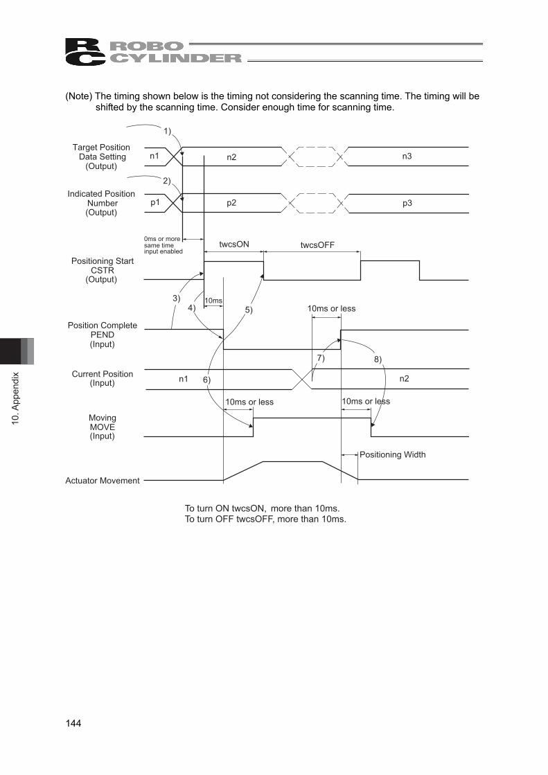
10. A
ppen
dix
144
(Note) The timing shown below is the timing not considering the scanning time. The timing will be shifted by the scanning time. Consider enough time for scanning time.
Target Position Data Setting
(Output)
(Output)
(Output)
Indicated Position Number
n1
p1
Positioning StartCSTR
Position CompletePEND(Input)
(Input)
(Input)
Current Position
MovingMOVE
Actuator Movement
Positioning Width
n2
p2 p3
n3
twcsOFFtwcsON
10ms
n1 n2
10ms or less
10ms or less10ms or less
6)
8)7)
5)4)3)
2)
1)
To turn ON twcsON, more than 10ms. To turn OFF twcsOFF, more than 10ms.
0ms or moresame timeinput enabled

10. Appendix
145
10.2.22 Operation Timings for Positioner 2 and Positioner 3 Modes The operation is to be made with the target position, speed, acceleration/deceleration, pressing width and pressing force set in the position data.
● Example of operation (positioning operation) (Preparation) Set the positioner 2 or positioner 3 mode to axis control command (DFC2,3 command).
Set the position data (target position, speed, acceleration/deceleration, etc.) to the position table.
(Note) If positioner 3 mode, have 1) and 2) at the same time. 1) Set the position No. where the speed and acceleration/deceleration, etc., have been set, in the
setup position No. internal relay (M) domain. 2) In the condition where the positioning completion (PEND) signal is turned “ON” or under
moving signal (MOVE) is turned “OFF”, turn “ON” the positioning start (CSTR) signal. The data items set in Step 1) is read in the controller at the startup (ON edge) of the CSTR
signal. 3) After the CSTR signal is turned “ON”, the PEND signal is turned OFF after 10ms. 4) After confirming that the PEND signal is turned “OFF” or MOVE signal is turned “ON”, turn
“OFF” the CSTR signal. Do not change the value in the target position internal relay (M) domain until the CSTR signal is turned “OFF”.
5) At the same time when the PEND signal is turned “OFF”, the MOVE signal is turned “ON”. 6) Once the remaining movement amount of the actuator gets into the range of the positioning
width set in the parameter, PEND signal turns ON if CSTR signal is OFF, and the complete position number is output to the complete position number internal relay (M) domain.
Accordingly, for the read of the completed position No. internal relay (M) domain when the positioning is completed, confirm it some time (remaining travel distance movement time) after the PEND signal is turned “ON”.
MOVE signal turns OFF at the same time as or within 10ms after PEND signal turns ON.
● Example of operation (pressing operation) For the pressing operation, set the current limit to the pressing box and pressing width to the pressing width box in the position data at the stage of (preparation). By conducting a positioning operation towards the set position number, the actuator performs a pressing operation.

10. A
ppen
dix
146
(Note) The timing shown below is the timing not considering the scanning time. The timing will be shifted by the scanning time. Consider enough time for scanning time.
Indicated Position Number p1
Positioning StartCSTR
Positioning CompletionPEND
MovingMOVE
Actuator Movement
Positioning Width
p2 p3
twcsOFFtwcsON
10ms
10ms or less10ms or less6)5)
4)3)
1)
2)
0ms or moresame timeinput enabled
To turn ON twcsON, more than 10ms. To turn OFF twcsOFF, more than 10ms.
(Output)
(Output)
(Input)
(Input)

10. Appendix
147
10.2.23 Operation for Direct Indication Mode It is operated with the data set in the DFC command assign the peculiar internal relay (M) domain, setup speed, acceleration/deceleration and pressing current limit setup.
● Example of operation (pressing operation) (Preparation) Set the direct indication mode to axis control command (DFC4 command). Also,
select the pressing method from CON and SEP. [refer to 10.2.16 Push-motion specification (PUSH)]
1) Set the target position data in the target position internal relay (M) domain. 2) Set the positioning width (pressing width) data in the positioning width internal relay (M) domain. 3) Set the speed data to the speed internal relay (M) area. 4) Set the acceleration/deceleration data to the acceleration/deceleration internal relay (M) domain. 5) Set the pressing current limit data in the pressing current limit value internal relay (M) domain. 6) Turn “ON” the pressing setup (PUSH) signal. 7) Specify the pressing direction using the pressing direction setup (DIR) signal. (Unnecessary for
SEP pressing method) 8) In the condition where the positioning completion (PEND) signal is turned “ON” or under
movement signal (MOVE) is turned “OFF”, turn “ON” the positioning start (CSTR) signal. The data items set in Steps 1) through 5) are read in the controller at the startup (ON edge) of
the CSTR signal. 9) After the CSTR signal is turned “ON”, the PEND signal is turned OFF after 10ms.
10) After confirming that the PEND signal is turned “OFF” or MOVE signal is turned “ON”, turn “OFF” the CSTR signal. Do not change any value in each internal relay (M) domain until the CSTR signal has been turned “OFF”.
11) The current position data is continuously updated. 12) When the CSTR signal is turned “OFF” and the motor current reaches the current limit value
set in Step 5), the PEND signal is turned “ON”. (Pressing complete) Even when the positioning width (pressing width) set in Step 2) is reached, in the case that the
current does not reach the motor current limit value set in Step 5), the pressing and a miss (PSEL) signal is turned “ON”. In this case, the PEND signal is not turned “ON” (pressing and a miss). (Pressing and a miss)
13) After the PEND signal or PSFL signal is turned “ON”, turn “OFF” the PUSH signal. 14) MOVE signal turns OFF at the same time as or within 10ms after PEND signal turns ON. (Note) When alarm being generated, output the alarm code.
Refer to section chapter 6 Troubleshooting in MSEP controller instruction manual. ● Example of operation (normal positioning operation) For the general positioning operation, set the signal in step 6) to “OFF”. When the remaining travel distance becomes within the range of the positioning width set in the position data, and the CSTR signal is turned “OFF”, the PEND signal is turned “ON”.
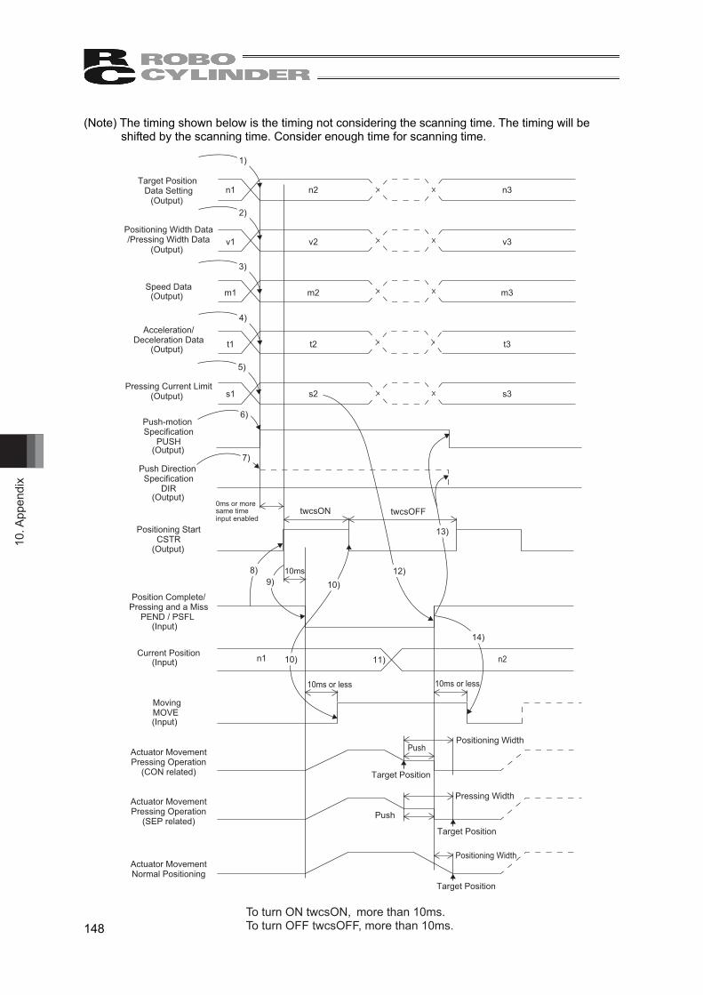
10. A
ppen
dix
148
(Note) The timing shown below is the timing not considering the scanning time. The timing will be shifted by the scanning time. Consider enough time for scanning time.
1)
2)
3)
4)
5)
6)
7)
8)9)
12)
11)
13)
14)
n1
v1
m1
t1
s1
3n2n
3v2v
3m2m
t2
3s2s
twcsON twcsOFF
10ms
n1
Target Position Data Setting
(Output)
(Output)
(Output)
(Output)
(Output)
(Output)
(Output)
(Output)
(Input)
(Input)
(Input)
Positioning Width Data/Pressing Width Data
Speed Data
Acceleration/Deceleration Data
Pressing Current Limit
Push-motion Specification
PUSH
Push Direction Specification
DIR
Positioning StartCSTR
Position Complete/Pressing and a Miss
PEND / PSFL
Current Position
MovingMOVE
Actuator MovementPressing Operation
(CON related)
Actuator MovementPressing Operation
(SEP related)
Actuator MovementNormal Positioning
10ms or less 10ms or less
n2
Push
Push
Target Position
Target Position
Positioning Width
Pressing Width
Positioning Width
Target Position
t3
10)
10)
To turn ON twcsON, more than 10ms. To turn OFF twcsOFF, more than 10ms.
0ms or moresame timeinput enabled
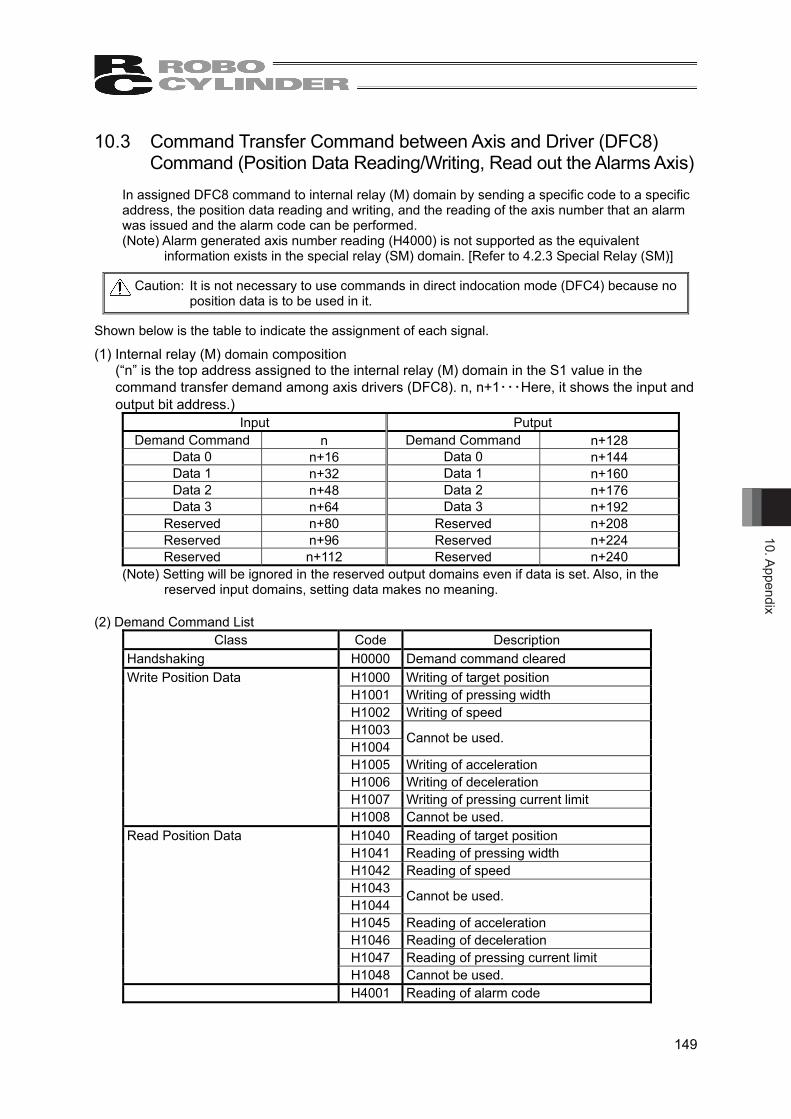
10. Appendix
149
10.3 Command Transfer Command between Axis and Driver (DFC8) Command (Position Data Reading/Writing, Read out the Alarms Axis)
In assigned DFC8 command to internal relay (M) domain by sending a specific code to a specific address, the position data reading and writing, and the reading of the axis number that an alarm was issued and the alarm code can be performed. (Note) Alarm generated axis number reading (H4000) is not supported as the equivalent
information exists in the special relay (SM) domain. [Refer to 4.2.3 Special Relay (SM)]
Caution: It is not necessary to use commands in direct indocation mode (DFC4) because no position data is to be used in it.
Shown below is the table to indicate the assignment of each signal.
(1) Internal relay (M) domain composition (“n” is the top address assigned to the internal relay (M) domain in the S1 value in the
command transfer demand among axis drivers (DFC8). n, n+1・・・Here, it shows the input and output bit address.)
Input Putput Demand Command n Demand Command n+128
Data 0 n+16 Data 0 n+144 Data 1 n+32 Data 1 n+160 Data 2 n+48 Data 2 n+176 Data 3 n+64 Data 3 n+192
Reserved n+80 Reserved n+208 Reserved n+96 Reserved n+224 Reserved n+112 Reserved n+240
(Note) Setting will be ignored in the reserved output domains even if data is set. Also, in the reserved input domains, setting data makes no meaning.
(2) Demand Command List
Class Code Description Handshaking H0000 Demand command cleared Write Position Data H1000 Writing of target position H1001 Writing of pressing width H1002 Writing of speed H1003 H1004
Cannot be used.
H1005 Writing of acceleration H1006 Writing of deceleration H1007 Writing of pressing current limit H1008 Cannot be used. Read Position Data H1040 Reading of target position H1041 Reading of pressing width H1042 Reading of speed H1043 H1044
Cannot be used.
H1045 Reading of acceleration H1046 Reading of deceleration H1047 Reading of pressing current limit H1048 Cannot be used. H4001 Reading of alarm code

10. A
ppen
dix
150
(3) Command details The input and output are constructed with 16 words in each input and output data in the internal relay (M) domain assigned in DFC8 Command. However, three words are the reserved domains for both input domains and output domains. ● The target position and current position are expressed using 2-word (32-bits) binary data. The
figures from –999999 to +999999 (Unit: 0.01mm) can be set. Negative numbers are to be dealt with two’s complement.
● Binary data of 2-word (32-bits) for the pressing band and values from -999999 to +999999 (unit: 0.01mm) can be set. Negative numbers are to be dealt with 2’s complement.
Caution: • Set the position data of the actuator, such as the target position and pressing band,
in the range of the software stroke (0 to effective stroke length). ● Binary data of 2-word (32-bits) for the speed and values from 1 to +999999 (unit: 1.0mm/s or
0.1mm/s). A change of the unit is to be conducted on Gateway Parameter Setting Tool. ● The Acceleration and Deceleration are expressed using 1-word (16-bits) binary data. The figures
from 1 to 300 (Unit: 0.01G) can be set. ● The pressing current limit value is expressed using 1-word (16-bits) binary data. The figures
from 0 (0%) to 255 (100%) can be set. ● Binary data of 1-word (16-bits) for the axis numbers and values from 0 (No.0) to 5 (No.5) can be
used. ● Binary data of 1-word (16-bits) for the position numbers and values from 0 (No.0) to 255
(No.255) can be used. ● The alarm code is expressed using 1-word (16-bits) binary data.
[Alarm code refer to 6.4 Alarm List in MSEP controller instruction manual]
Caution: Have the setting with values available in the range of for speed, acceleration/deceleration and pressing current of the actuator. (Refer to the catalog or instruction manual of the actuator.) Otherwise, it may cause an abnormal condition of the servo or a malfunction of the actuator such as the alarm codes 0A3 “Position Command Information Data Error”, 0C0 “Excess Actual Speed”, 0C8 “Overcurrent”, 0CA “Overheated” or 0E0 “Overloaded”.
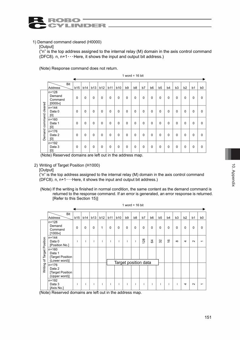
10. Appendix
151
1) Demand command cleared (H0000) [Output] (“n” is the top address assigned to the internal relay (M) domain in the axis control command (DFC8). n, n+1・・・Here, it shows the input and output bit address.) (Note) Response command does not return.
Bit
Address b15 b14 b13 b12 b11 b10 b9 b8 b7 b6 b5 b4 b3 b2 b1 b0 n+128 Demand Command [0000H]
0 0 0 0 0 0 0 0 0 0 0 0 0 0 0 0
n+144 Data 0 [0]
0 0 0 0 0 0 0 0 0 0 0 0 0 0 0 0
n+160 Data 1 [0]
0 0 0 0 0 0 0 0 0 0 0 0 0 0 0 0
n+176 Data 2 [0]
0 0 0 0 0 0 0 0 0 0 0 0 0 0 0 0
Dem
and
com
man
d cl
eare
d
n+192 Data 3 [0]
0 0 0 0 0 0 0 0 0 0 0 0 0 0 0 0
(Note) Reserved domains are left out in the address map.
2) Writing of Target Position (H1000) [Output] (“n” is the top address assigned to the internal relay (M) domain in the axis control command (DFC8). n, n+1・・・Here, it shows the input and output bit address.) (Note) If the writing is finished in normal condition, the same content as the demand command is
returned to the response command. If an error is generated, an error response is returned. [Refer to this Section 15)]
Bit
Address b15 b14 b13 b12 b11 b10 b9 b8 b7 b6 b5 b4 b3 b2 b1 b0 n+128 Demand Command [1000H]
0 0 0 1 0 0 0 0 0 0 0 0 0 0 0 0
n+144 Data 0 [Position No.]
– – – – – – – – 128
64
32
16
8 4 2 1
n+160 Data 1 [Target Position (Lower word)]
n+176 Data 2 [Target Position (Upper word)]
Writ
ing
of T
arge
t Pos
ition
n+192 Data 3 [Axis No.]
– – – – – – – – – – – – – 4 2 1
(Note) Reserved domains are left out in the address map.
1 word = 16 bit
1 word = 16 bit
Target position data
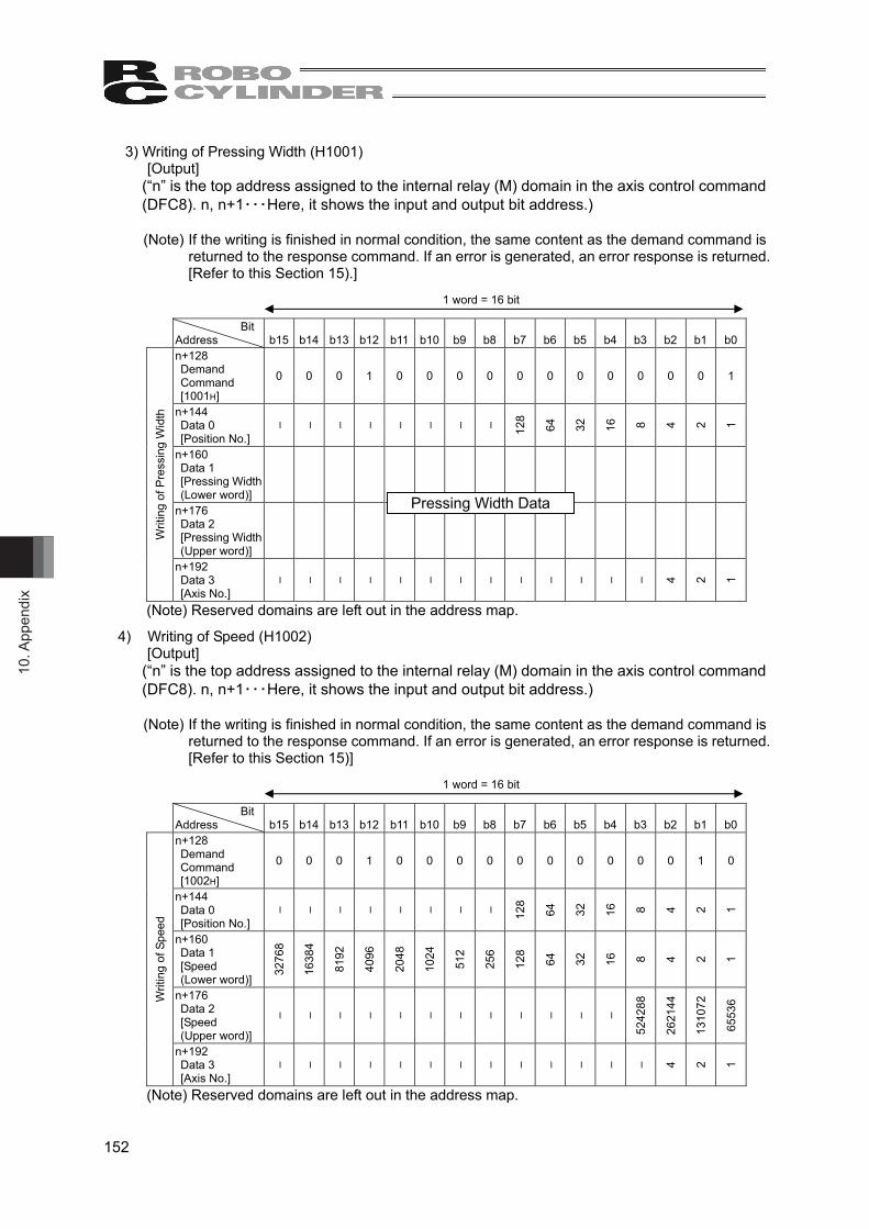
10. A
ppen
dix
152
3) Writing of Pressing Width (H1001) [Output]
(“n” is the top address assigned to the internal relay (M) domain in the axis control command (DFC8). n, n+1・・・Here, it shows the input and output bit address.) (Note) If the writing is finished in normal condition, the same content as the demand command is
returned to the response command. If an error is generated, an error response is returned. [Refer to this Section 15).]
Bit Address b15 b14 b13 b12 b11 b10 b9 b8 b7 b6 b5 b4 b3 b2 b1 b0 n+128 Demand Command [1001H]
0 0 0 1 0 0 0 0 0 0 0 0 0 0 0 1
n+144 Data 0 [Position No.]
– – – – – – – – 128
64
32
16
8 4 2 1
n+160 Data 1 [Pressing Width (Lower word)]
n+176 Data 2 [Pressing Width (Upper word)]
Writ
ing
of P
ress
ing
Wid
th
n+192 Data 3 [Axis No.]
– – – – – – – – – – – – – 4 2 1
(Note) Reserved domains are left out in the address map.
4) Writing of Speed (H1002) [Output]
(“n” is the top address assigned to the internal relay (M) domain in the axis control command (DFC8). n, n+1・・・Here, it shows the input and output bit address.)
(Note) If the writing is finished in normal condition, the same content as the demand command is
returned to the response command. If an error is generated, an error response is returned. [Refer to this Section 15)]
Bit Address b15 b14 b13 b12 b11 b10 b9 b8 b7 b6 b5 b4 b3 b2 b1 b0 n+128 Demand Command [1002H]
0 0 0 1 0 0 0 0 0 0 0 0 0 0 1 0
n+144 Data 0 [Position No.]
– – – – – – – – 128
64
32
16
8 4 2 1
n+160 Data 1 [Speed (Lower word)]
3276
8
1638
4
8192
4096
2048
1024
512
256
128
64
32
16
8 4 2 1
n+176 Data 2 [Speed (Upper word)]
– – – – – – – – – – – –
5242
88
2621
44
1310
72
6553
6 Writ
ing
of S
peed
n+192 Data 3 [Axis No.]
– – – – – – – – – – – – – 4 2 1
(Note) Reserved domains are left out in the address map.
1 word = 16 bit
1 word = 16 bit
Pressing Width Data

10. Appendix
153
5) Writing of Acceleration (H1005) [Output]
(“n” is the top address assigned to the internal relay (M) domain in the axis control command (DFC8). n, n+1・・・Here, it shows the input and output bit address.)
(Note) If the writing is finished in normal condition, the same content as the demand command is
returned to the response command. If an error is generated, an error response is returned. [Refer to this Section 15)]
Bit Address b15 b14 b13 b12 b11 b10 b9 b8 b7 b6 b5 b4 b3 b2 b1 b0 n+128 Demand Command [1005H]
0 0 0 1 0 0 0 0 0 0 0 0 0 1 0 1
n+144 Data 0 [Position No.]
– – – – – – – – 128
64
32
16
8 4 2 1
n+160 Data 1 [Acceleration]
– – – – – – – 256
128
64
32
16
8 4 2 1
n+176 Data 2 [0]
0 0 0 0 0 0 0 0 0 0 0 0 0 0 0 0 Writ
ing
of A
ccel
erat
ion
n+192 Data 3 [Axis No.]
– – – – – – – – – – – – – 4 2 1
(Note) Reserved domains are left out in the address map. 6) Writing of Deceleration (H1006)
[Output] (“n” is the top address assigned to the internal relay (M) domain in the axis control command (DFC8). n, n+1・・・Here, it shows the input and output bit address.)
(Note) If the writing is finished in normal condition, the same content as the demand command is
returned to the response command. If an error is generated, an error response is returned. [Refer to this Section 15).]
Bit Address b15 b14 b13 b12 b11 b10 b9 b8 b7 b6 b5 b4 b3 b2 b1 b0 n+128 Demand Command [1006H]
0 0 0 1 0 0 0 0 0 0 0 0 0 1 1 0
n+144 Data 0 [Position No.]
– – – – – – – – 128
64
32
16
8 4 2 1
n+160 Data 1 [Deceleration]
– – – – – – – 256
128
64
32
16
8 4 2 1
n+176 Data 2 [0]
0 0 0 0 0 0 0 0 0 0 0 0 0 0 0 0 Writ
ing
of D
ecel
erat
ion
n+192 Data 3 [Axis No.]
– – – – – – – – – – – – – 4 2 1
(Note) Reserved domains are left out in the address map.
1 word = 16 bit
1 word = 16 bit
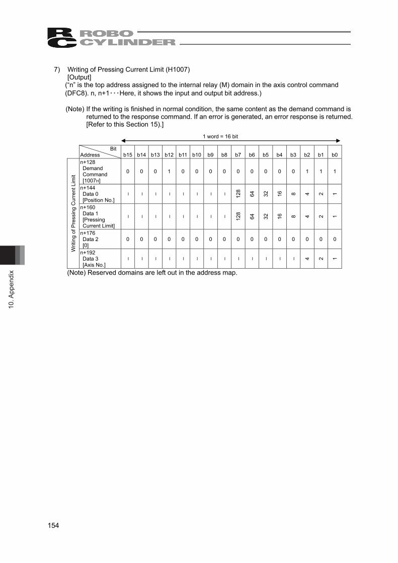
10. A
ppen
dix
154
7) Writing of Pressing Current Limit (H1007) [Output]
(“n” is the top address assigned to the internal relay (M) domain in the axis control command (DFC8). n, n+1・・・Here, it shows the input and output bit address.) (Note) If the writing is finished in normal condition, the same content as the demand command is
returned to the response command. If an error is generated, an error response is returned. [Refer to this Section 15).]
Bit Address b15 b14 b13 b12 b11 b10 b9 b8 b7 b6 b5 b4 b3 b2 b1 b0 n+128 Demand Command [1007H]
0 0 0 1 0 0 0 0 0 0 0 0 0 1 1 1
n+144 Data 0 [Position No.]
– – – – – – – – 128
64
32
16
8 4 2 1
n+160 Data 1 [Pressing Current Limit]
– – – – – – – – 128
64
32
16
8 4 2 1
n+176 Data 2 [0]
0 0 0 0 0 0 0 0 0 0 0 0 0 0 0 0
Writ
ing
of P
ress
ing
Cur
rent
Lim
it
n+192 Data 3 [Axis No.]
– – – – – – – – – – – – – 4 2 1
(Note) Reserved domains are left out in the address map.
1 word = 16 bit

10. Appendix
155
8) Reading of Target Position (H1040) [Output]
(“n” is the top address assigned to the internal relay (M) domain in the axis control command (DFC8). n, n+1・・・Here, it shows the input and output bit address.)
Bit
Address b15 b14 b13 b12 b11 b10 b9 b8 b7 b6 b5 b4 b3 b2 b1 b0 n+128 Demand Command [1040H]
0 0 0 1 0 0 0 0 0 1 0 0 0 0 0 0
n+144 Data 0 [Position No.]
– – – – – – – – 128
64
32
16
8 4 2 1
n+160 Data 1 [0]
0 0 0 0 0 0 0 0 0 0 0 0 0 0 0 0
n+176 Data 2 [0]
0 0 0 0 0 0 0 0 0 0 0 0 0 0 0 0
Rea
ding
of T
arge
t Pos
ition
n+192 Data 3 [Axis No.]
– – – – – – – – – – – – – 4 2 1
(Note) Reserved domains are left out in the address map.
* If the target position command gets input, the target position data will be set in the input Data 1 and Data2.
[Input] (“n” is the top address assigned to the internal relay (M) domain in the axis control command (DFC8). n, n+1・・・Here, it shows the input and output bit address.)
Bit
Address b15 b14 b13 b12 b11 b10 b9 b8 b7 b6 b5 b4 b3 b2 b1 b0 n Response Command [1040H]
0 0 0 1 0 0 0 0 0 1 0 0 0 0 0 0
n+16 Data 0 [Position No.]
– – – – – – – – 128
64
32
16
8 4 2 1
n+32 Data 1 [Target Position (Lower word)]
n+48 Data 2 [Target Position (Upper word)]
Rea
ding
of T
arge
t Pos
ition
n+64 Data 3 [Axis No.]
– – – – – – – – – – – – – 4 2 1
(Note) Reserved domains are left out in the address map.
1 word = 16 bit
1 word = 16 bit
Target position Data

10. A
ppen
dix
156
9) Reading of Pressing Width (H1041) [Output]
(“n” is the top address assigned to the internal relay (M) domain in the axis control command (DFC8). n, n+1・・・Here, it shows the input and output bit address.)
Bit
Address b15 b14 b13 b12 b11 b10 b9 b8 b7 b6 b5 b4 b3 b2 b1 b0 n+128 Demand Command [1041H]
0 0 0 1 0 0 0 0 0 1 0 0 0 0 0 1
n+144 Data 0 [Position No.]
– – – – – – – – 128
64
32
16
8 4 2 1
n+160 Data 1 [0]
0 0 0 0 0 0 0 0 0 0 0 0 0 0 0 0
n+176 Data 2 [0]
0 0 0 0 0 0 0 0 0 0 0 0 0 0 0 0
Rea
ding
of P
ress
ing
Wid
th
n+192 Data 3 [Axis No.]
– – – – – – – – – – – – – 4 2 1
(Note) Reserved domains are left out in the address map. * If the reading of pressing width command gets input, the pressing width data will be set in the
input Data 1 and Data2.
[Input] (“n” is the top address assigned to the internal relay (M) domain in the axis control command (DFC8). n, n+1・・・Here, it shows the input and output bit address.)
Bit
Address b15 b14 b13 b12 b11 b10 b9 b8 b7 b6 b5 b4 b3 b2 b1 b0 n Response Command [1041H]
0 0 0 1 0 0 0 0 0 1 0 0 0 0 0 1
n+16 Data 0 [Position No.]
– – – – – – – – 128
64
32
16
8 4 2 1
n+32 Data 1 [Pressing Width (Lower word)]
n+48 Data 2 [Pressing Width (Upper word)]
Rea
ding
of P
ress
ing
Wid
th
n+64 Data 3 [Axis No.]
– – – – – – – – – – – – – 4 2 1
(Note) Reserved domains are left out in the address map.
1 word = 16 bit
1 word = 16 bit
Pressing Width Data
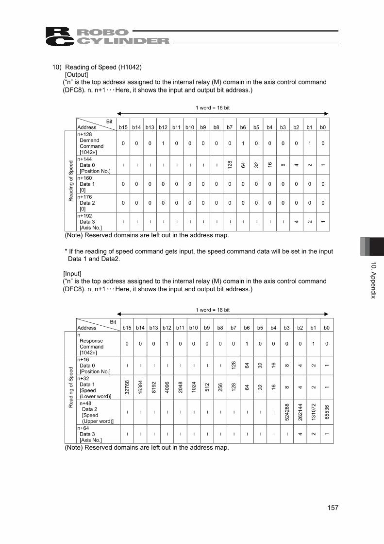
10. Appendix
157
10) Reading of Speed (H1042) [Output]
(“n” is the top address assigned to the internal relay (M) domain in the axis control command (DFC8). n, n+1・・・Here, it shows the input and output bit address.)
Bit
Address b15 b14 b13 b12 b11 b10 b9 b8 b7 b6 b5 b4 b3 b2 b1 b0 n+128 Demand Command [1042H]
0 0 0 1 0 0 0 0 0 1 0 0 0 0 1 0
n+144 Data 0 [Position No.]
– – – – – – – – 128
64
32
16
8 4 2 1
n+160 Data 1 [0]
0 0 0 0 0 0 0 0 0 0 0 0 0 0 0 0
n+176 Data 2 [0]
0 0 0 0 0 0 0 0 0 0 0 0 0 0 0 0 Rea
ding
of S
peed
n+192 Data 3 [Axis No.]
– – – – – – – – – – – – – 4 2 1
(Note) Reserved domains are left out in the address map. * If the reading of speed command gets input, the speed command data will be set in the input Data 1 and Data2.
[Input] (“n” is the top address assigned to the internal relay (M) domain in the axis control command (DFC8). n, n+1・・・Here, it shows the input and output bit address.)
Bit
Address b15 b14 b13 b12 b11 b10 b9 b8 b7 b6 b5 b4 b3 b2 b1 b0 n Response Command [1042H]
0 0 0 1 0 0 0 0 0 1 0 0 0 0 1 0
n+16 Data 0 [Position No.]
– – – – – – – – 128
64
32
16
8 4 2 1
n+32 Data 1 [Speed (Lower word)]
3276
8
1638
4
8192
4096
2048
1024
512
256
128
64
32
16
8 4 2 1
n+48 Data 2 [Speed (Upper word)]
– – – – – – – – – – – –
5242
88
2621
44
1310
72
6553
6 Rea
ding
of S
peed
n+64 Data 3 [Axis No.]
– – – – – – – – – – – – – 4 2 1
(Note) Reserved domains are left out in the address map.
1 word = 16 bit
1 word = 16 bit
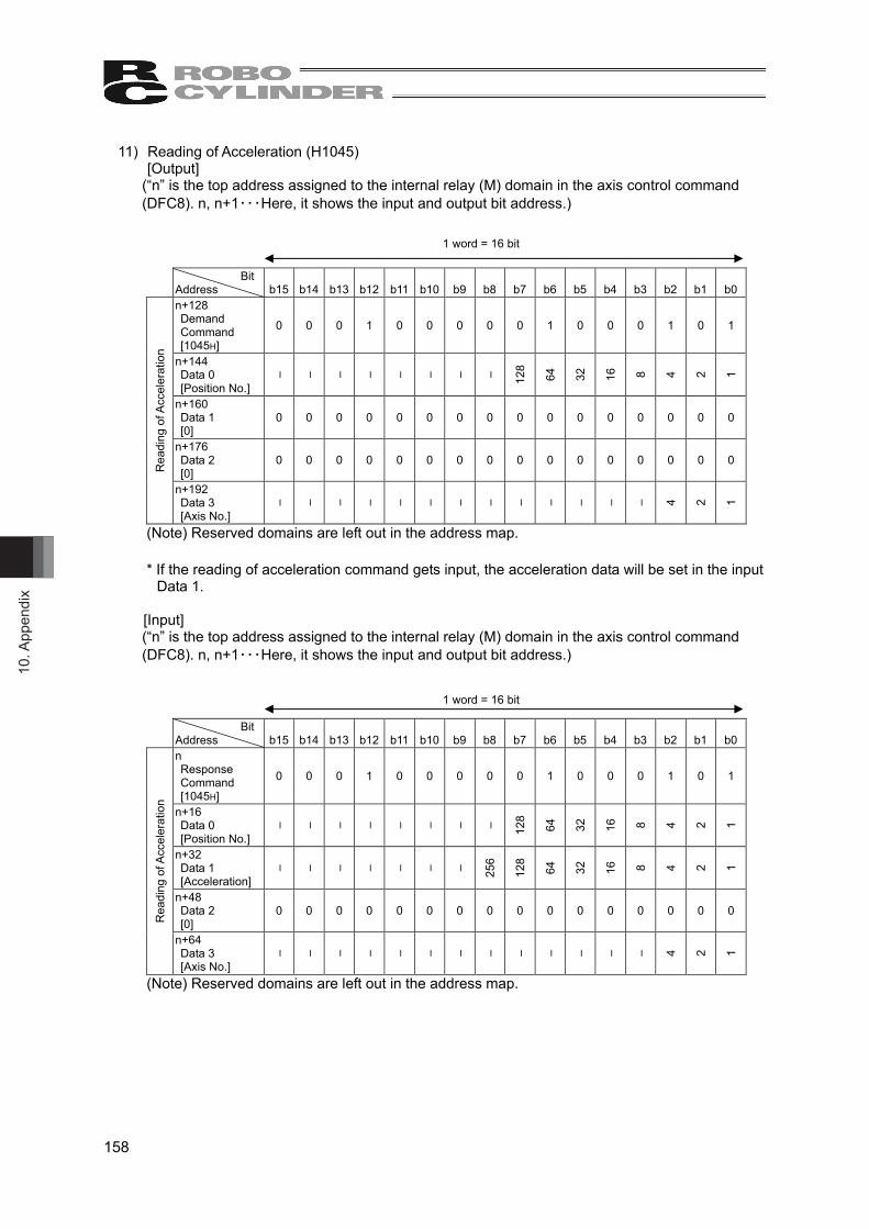
10. A
ppen
dix
158
11) Reading of Acceleration (H1045) [Output]
(“n” is the top address assigned to the internal relay (M) domain in the axis control command (DFC8). n, n+1・・・Here, it shows the input and output bit address.)
Bit
Address b15 b14 b13 b12 b11 b10 b9 b8 b7 b6 b5 b4 b3 b2 b1 b0 n+128 Demand Command [1045H]
0 0 0 1 0 0 0 0 0 1 0 0 0 1 0 1
n+144 Data 0 [Position No.]
– – – – – – – – 128
64
32
16
8 4 2 1
n+160 Data 1 [0]
0 0 0 0 0 0 0 0 0 0 0 0 0 0 0 0
n+176 Data 2 [0]
0 0 0 0 0 0 0 0 0 0 0 0 0 0 0 0
Rea
ding
of A
ccel
erat
ion
n+192 Data 3 [Axis No.]
– – – – – – – – – – – – – 4 2 1
(Note) Reserved domains are left out in the address map.
* If the reading of acceleration command gets input, the acceleration data will be set in the input Data 1.
[Input] (“n” is the top address assigned to the internal relay (M) domain in the axis control command (DFC8). n, n+1・・・Here, it shows the input and output bit address.)
Bit
Address b15 b14 b13 b12 b11 b10 b9 b8 b7 b6 b5 b4 b3 b2 b1 b0 n Response Command [1045H]
0 0 0 1 0 0 0 0 0 1 0 0 0 1 0 1
n+16 Data 0 [Position No.]
– – – – – – – – 128
64
32
16
8 4 2 1
n+32 Data 1 [Acceleration]
– – – – – – – 256
128
64
32
16
8 4 2 1
n+48 Data 2 [0]
0 0 0 0 0 0 0 0 0 0 0 0 0 0 0 0
Rea
ding
of A
ccel
erat
ion
n+64 Data 3 [Axis No.]
– – – – – – – – – – – – – 4 2 1
(Note) Reserved domains are left out in the address map.
1 word = 16 bit
1 word = 16 bit

10. Appendix
159
12) Reading of Deceleration (H1046) [Output]
(“n” is the top address assigned to the internal relay (M) domain in the axis control command (DFC8). n, n+1・・・Here, it shows the input and output bit address.)
Bit
Address b15 b14 b13 b12 b11 b10 b9 b8 b7 b6 b5 b4 b3 b2 b1 b0 n+128 Demand Command [1046H]
0 0 0 1 0 0 0 0 0 1 0 0 0 1 1 0
n+144 Data 0 [Position No.]
– – – – – – – – 128
64
32
16
8 4 2 1
n+160 Data 1 [0]
0 0 0 0 0 0 0 0 0 0 0 0 0 0 0 0
n+176 Data 2 [0]
0 0 0 0 0 0 0 0 0 0 0 0 0 0 0 0
Rea
ding
of D
ecel
erat
ion
n+192 Data 3 [Axis No.]
– – – – – – – – – – – – – 4 2 1
(Note) Reserved domains are left out in the address map.
* If the reading of deceleration command gets input, the deceleration data will be set in the input Data 1.
[Input] (“n” is the top address assigned to the internal relay (M) domain in the axis control command (DFC8). n, n+1・・・Here, it shows the input and output bit address.)
Bit
Address b15 b14 b13 b12 b11 b10 b9 b8 b7 b6 b5 b4 b3 b2 b1 b0 n Response Command [1046H]
0 0 0 1 0 0 0 0 0 1 0 0 0 1 1 0
n+16 Data 0 [Position No.]
– – – – – – – – 128
64
32
16
8 4 2 1
n+32 Data 1 [Deceleration]
– – – – – – – 256
128
64
32
16
8 4 2 1
n+48 Data 2 [0]
0 0 0 0 0 0 0 0 0 0 0 0 0 0 0 0
Rea
ding
of D
ecel
erat
ion
n+64 Data 3 [Axis No.]
– – – – – – – – – – – – – 4 2 1
(Note) Reserved domains are left out in the address map.
1 word = 16 bit
1 word = 16 bit
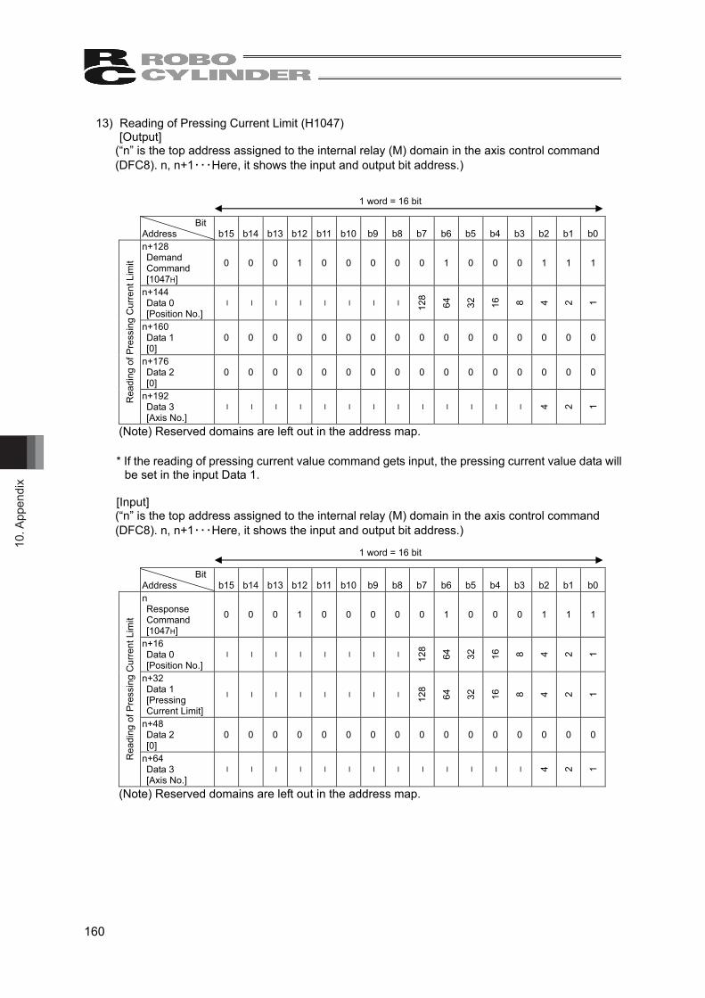
10. A
ppen
dix
160
13) Reading of Pressing Current Limit (H1047) [Output]
(“n” is the top address assigned to the internal relay (M) domain in the axis control command (DFC8). n, n+1・・・Here, it shows the input and output bit address.)
Bit
Address b15 b14 b13 b12 b11 b10 b9 b8 b7 b6 b5 b4 b3 b2 b1 b0 n+128 Demand Command [1047H]
0 0 0 1 0 0 0 0 0 1 0 0 0 1 1 1
n+144 Data 0 [Position No.]
– – – – – – – – 128
64
32
16
8 4 2 1
n+160 Data 1 [0]
0 0 0 0 0 0 0 0 0 0 0 0 0 0 0 0
n+176 Data 2 [0]
0 0 0 0 0 0 0 0 0 0 0 0 0 0 0 0
Rea
ding
of P
ress
ing
Cur
rent
Lim
it
n+192 Data 3 [Axis No.]
– – – – – – – – – – – – – 4 2 1
(Note) Reserved domains are left out in the address map.
* If the reading of pressing current value command gets input, the pressing current value data will be set in the input Data 1.
[Input] (“n” is the top address assigned to the internal relay (M) domain in the axis control command (DFC8). n, n+1・・・Here, it shows the input and output bit address.)
Bit
Address b15 b14 b13 b12 b11 b10 b9 b8 b7 b6 b5 b4 b3 b2 b1 b0 n Response Command [1047H]
0 0 0 1 0 0 0 0 0 1 0 0 0 1 1 1
n+16 Data 0 [Position No.]
– – – – – – – – 128
64
32
16
8 4 2 1
n+32 Data 1 [Pressing Current Limit]
– – – – – – – – 128
64
32
16
8 4 2 1
n+48 Data 2 [0]
0 0 0 0 0 0 0 0 0 0 0 0 0 0 0 0
Rea
ding
of P
ress
ing
Cur
rent
Lim
it
n+64 Data 3 [Axis No.]
– – – – – – – – – – – – – 4 2 1
(Note) Reserved domains are left out in the address map.
1 word = 16 bit
1 word = 16 bit
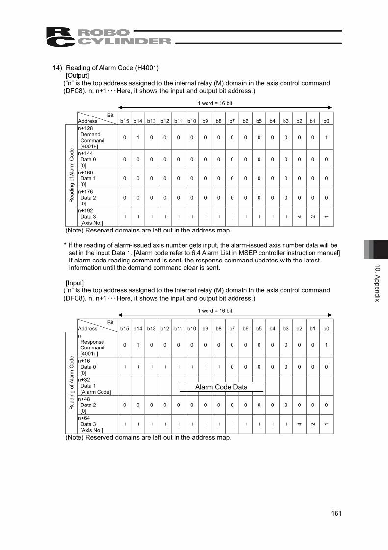
10. Appendix
161
14) Reading of Alarm Code (H4001) [Output]
(“n” is the top address assigned to the internal relay (M) domain in the axis control command (DFC8). n, n+1・・・Here, it shows the input and output bit address.)
Bit
Address b15 b14 b13 b12 b11 b10 b9 b8 b7 b6 b5 b4 b3 b2 b1 b0 n+128 Demand Command [4001H]
0 1 0 0 0 0 0 0 0 0 0 0 0 0 0 1
n+144 Data 0 [0]
0 0 0 0 0 0 0 0 0 0 0 0 0 0 0 0
n+160 Data 1 [0]
0 0 0 0 0 0 0 0 0 0 0 0 0 0 0 0
n+176 Data 2 [0]
0 0 0 0 0 0 0 0 0 0 0 0 0 0 0 0 Rea
ding
of A
larm
Cod
e
n+192 Data 3 [Axis No.]
– – – – – – – – – – – – – 4 2 1
(Note) Reserved domains are left out in the address map. * If the reading of alarm-issued axis number gets input, the alarm-issued axis number data will be
set in the input Data 1. [Alarm code refer to 6.4 Alarm List in MSEP controller instruction manual] If alarm code reading command is sent, the response command updates with the latest information until the demand command clear is sent.
[Input] (“n” is the top address assigned to the internal relay (M) domain in the axis control command (DFC8). n, n+1・・・Here, it shows the input and output bit address.)
Bit
Address b15 b14 b13 b12 b11 b10 b9 b8 b7 b6 b5 b4 b3 b2 b1 b0 n Response Command [4001H]
0 1 0 0 0 0 0 0 0 0 0 0 0 0 0 1
n+16 Data 0 [0]
– – – – – – – – 0 0 0 0 0 0 0 0
n+32 Data 1 [Alarm Code]
n+48 Data 2 [0]
0 0 0 0 0 0 0 0 0 0 0 0 0 0 0 0 Rea
ding
of A
larm
Cod
e
n+64 Data 3 [Axis No.]
– – – – – – – – – – – – – 4 2 1
(Note) Reserved domains are left out in the address map.
1 word = 16 bit
1 word = 16 bit
Alarm Code Data
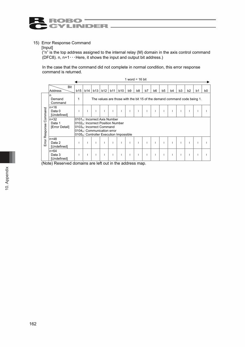
10. A
ppen
dix
162
15) Error Response Command [Input] (“n” is the top address assigned to the internal relay (M) domain in the axis control command (DFC8). n, n+1・・・Here, it shows the input and output bit address.) In the case that the command did not complete in normal condition, this error response command is returned.
Bit Address b15 b14 b13 b12 b11 b10 b9 b8 b7 b6 b5 b4 b3 b2 b1 b0 n Demand Command
1 The values are those with the bit 15 of the demand command code being 1.
n+16 Data 0 [Undefined]
– – – – – – – – – – – – – – – –
n+32 Data 1 [Error Detail]
0101H: Incorrect Axis Number 0102H: Incorrect Position Number 0103H: Incorrect Command 0104H: Communication error 0105H: Controller Execution Impossible
n+48 Data 2 [Undefined]
– – – – – – – – – – – – – – – –
Erro
r Res
pons
e C
omm
and
n+64 Data 3 [Undefined]
– – – – – – – – – – – – – – – –
(Note) Reserved domains are left out in the address map.
1 word = 16 bit
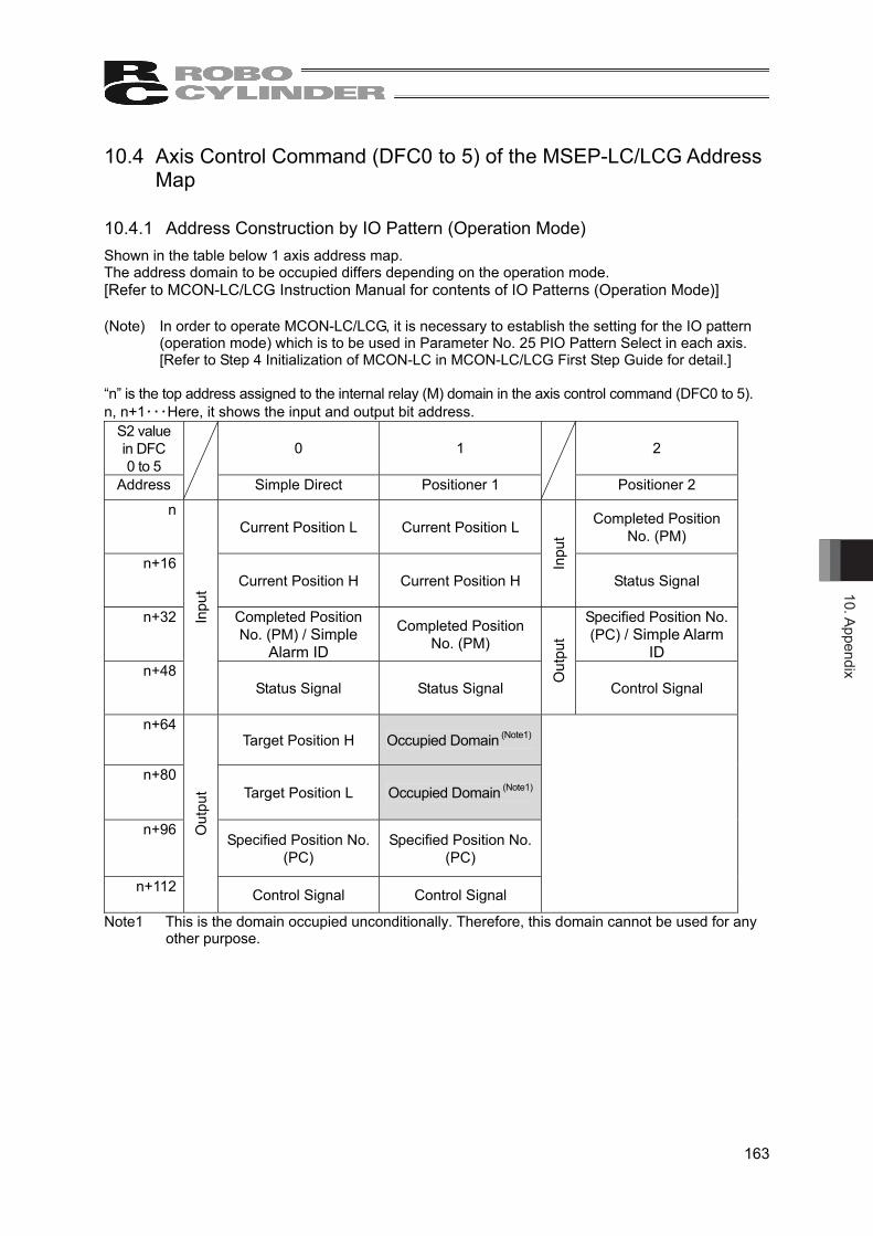
10. Appendix
163
10.4 Axis Control Command (DFC0 to 5) of the MSEP-LC/LCG Address Map
10.4.1 Address Construction by IO Pattern (Operation Mode) Shown in the table below 1 axis address map. The address domain to be occupied differs depending on the operation mode. [Refer to MCON-LC/LCG Instruction Manual for contents of IO Patterns (Operation Mode)] (Note) In order to operate MCON-LC/LCG, it is necessary to establish the setting for the IO pattern
(operation mode) which is to be used in Parameter No. 25 PIO Pattern Select in each axis. [Refer to Step 4 Initialization of MCON-LC in MCON-LC/LCG First Step Guide for detail.]
“n” is the top address assigned to the internal relay (M) domain in the axis control command (DFC0 to 5). n, n+1・・・Here, it shows the input and output bit address.
S2 value in DFC 0 to 5
0 1 2
Address
Simple Direct Positioner 1
Positioner 2 n
Current Position L Current Position L Completed Position No. (PM)
n+16 Current Position H Current Position H
Inpu
t Status Signal
n+32
Completed Position No. (PM) / Simple
Alarm ID
Completed Position No. (PM)
Specified Position No. (PC) / Simple Alarm
ID n+48
Inpu
t
Status Signal Status Signal
Out
put
Control Signal
n+64 Target Position H Occupied Domain (Note1)
n+80 Target Position L Occupied Domain (Note1)
n+96 Specified Position No.
(PC) Specified Position No.
(PC)
n+112
Out
put
Control Signal Control Signal
Note1 This is the domain occupied unconditionally. Therefore, this domain cannot be used for any other purpose.

10. A
ppen
dix
164
S2 value in DFC 0 to 5
3 4 5
Address
Positioner 3
Direct Number Indication
Positioner 5
n Completed Position No. (PM)
n+8 Inpu
t
Status Signal Current Position L Current Position
n+16 Specified Position No. (PC)
n+24 Out
put
Control Signal
Current Position H
Inpu
t
Status Signal / Completed Position
No.
n+32 Command Current Value
L Specified Position
No.
n+48 Command Current Value
H
Out
put
Control Signal
n+64 Current Speed
n+80 Occupied Domain (Note1)
n+96 Alarm Code
n+112
Inpu
t
Status Signal
n+128 Target Position L
n+144 Target Position H
n+160 Positioning Width L
n+176 Positioning Width H
n+192 Speed
n+208 Acceleration/Deceleration
n+224 Pressing Current
Limit Value n+240
Out
put
Control Signal
Note 1 This is the domain occupied unconditionally. Therefore, this domain cannot be used for any other purpose.

10. Appendix
165
S2 value in DFC 0 to 5
6
Address
Remote I/O Mode
n
Inpu
t
Input port No. 0 to 15
n+16
Out
put
Output port No. 0 to 15
10.5 SCON-LC/LCG Address Map
10.5.1 Address Construction by Operation Mode
Shown in the table below 1 axis address map. The address domain to be occupied differs depending on the operation mode. [Refer in each fieldbus instruction manual for SCON-LC/LCG for contents of each operation mode.] [Input]
Parameter No.84 0 1 2
Address Remote I/O Mode
Position / Simple Direct Mode Half Direct Mode
M2048 to M2063 Input port No. 0 to 15 Current Position L Current Position L
M2064 to M2079 Current Position H Current Position H
M2080 to M2095 Completed Position No.
(PM) / Simple Alarm ID Command Current Value
L M2096 to M2111 Status Signal Command Current Value
H M2112 to M2127 Current Speed L
M2128 to M2143 Current Speed H
M2144 to M2159 Alarm Code
M2160 to M2175 Status Signal
M2176 to M2191
M2192 to M2207
M2208 to M2223
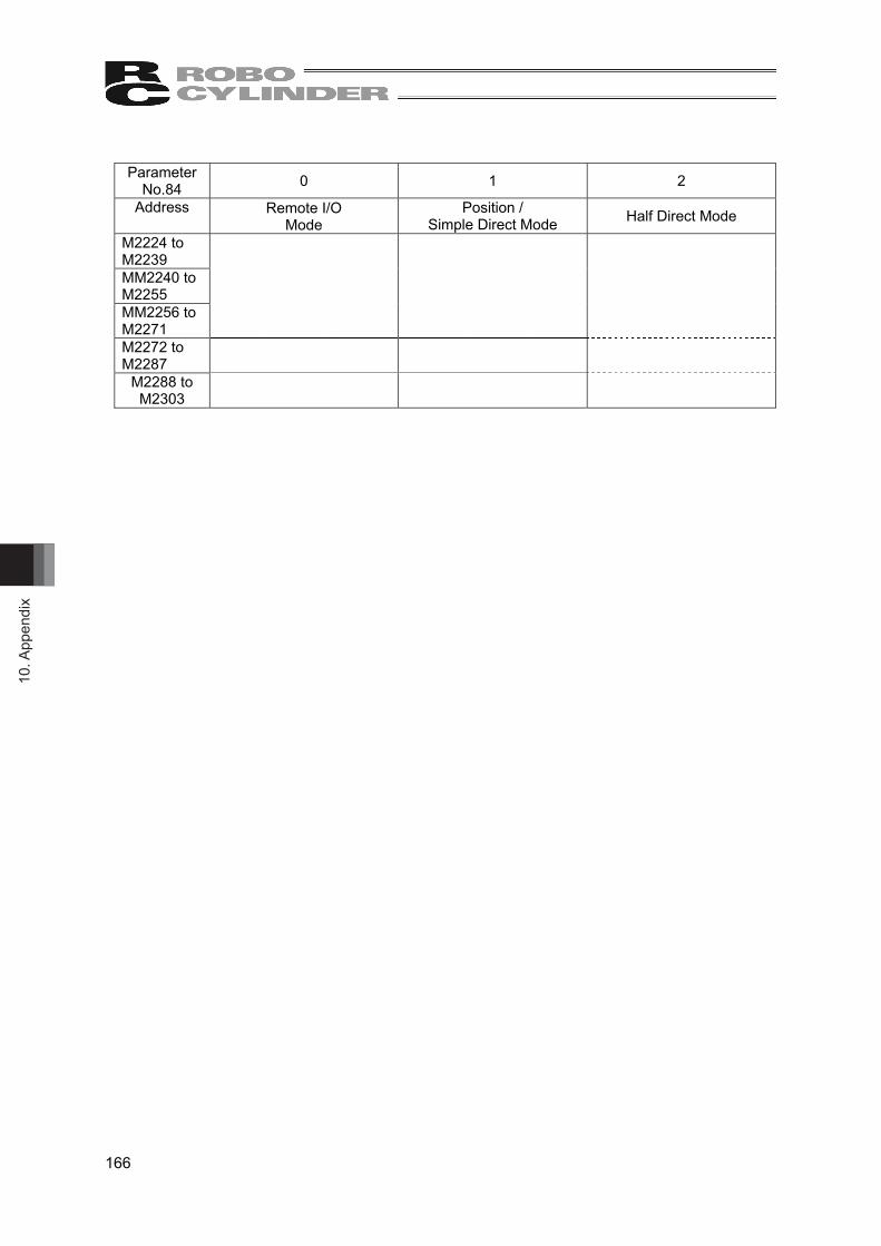
10. A
ppen
dix
166
Parameter
No.84 0 1 2
Address Remote I/O Mode
Position / Simple Direct Mode Half Direct Mode
M2224 to M2239
MM2240 to M2255
MM2256 to M2271
M2272 to M2287
M2288 to M2303
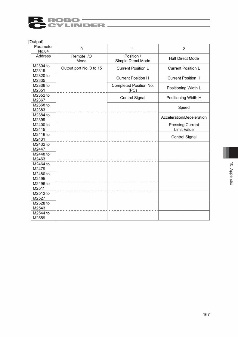
10. Appendix
167
[Output] Parameter
No.84 0 1 2
Address Remote I/O Mode
Position / Simple Direct Mode Half Direct Mode
M2304 to M2319 Output port No. 0 to 15 Current Position L Current Position L
M2320 to M2335 Current Position H Current Position H
M2336 to M2351 Completed Position No.
(PC) Positioning Width L
M2352 to M2367 Control Signal Positioning Width H
M2368 to M2383 Speed
M2384 to M2399 Acceleration/Deceleration
M2400 to M2415 Pressing Current
Limit Value M2416 to M2431 Control Signal
M2432 to M2447
M2448 to M2463
M2464 to M2479
M2480 to M2495
M2496 to M2511
M2512 to M2527
M2528 to M2543
M2544 to M2559

10. A
ppen
dix
168
[Input] Parameter
No.84 3 4 5 Address Full Direct Mode Remote I/O
Mode 2 Position /
Simple Direct Mode 2 M2048 to M2063 Current Position L Input port No. 0 to 15 Current Position L
M2064 to M2079 Current Position H Occupied Domain (Note1) Current Position H
M2080 to M2095 Command Current Value L Current Position L Completed Position No.
(PM) / Simple Alarm ID M2096 to M2111
Command Current Value H Current Position H Status Signal
M2112 to M2127 Current Speed L Command Current Value L
M2128 to M2143 Current Speed H Command Current Value
H
M2144 to M2159 Alarm Code
M2160 to M2175 Occupied Domain (Note1)
M2176 to M2191 Current Load L
M2192 to M2207 Current Load H
M2208 to M2223
Total Times of Movement L
M2224 to M2239
Total Times of Movement H
MM2240 to M2255 Total Driving Distance L
MM2256 to M2271 Total Driving Distance H
M2272 to M2287 Status Signal 1
M2288 to M2303 Status Signal 2
Note 1 This is the domain occupied unconditionally. Therefore, this domain cannot be used for any other purpose.

10. Appendix
169
[Output] Parameter
No.84 3 4 5
Address Full Direct Mode Remote I/O Mode 2
Position / Simple Direct Mode 2
M2304 to M2319 Target Position L Output port No. 0 to 15 Target Position L
M2320 to M2335 Target Position H Target Position H
M2336 to M2351 Positioning Width L Specified Position No.
(PC) M2352 to M2367 Positioning Width H Control Signal
M2368 to M2383 Speed L
M2384 to M2399 Speed H
M2400 to M2415 Zone Boundary + L
M2416 to M2431 Zone Boundary + H
M2432 to M2447 Zone Boundary - L
M2448 to M2463 Zone Boundary - H
M2464 to M2479 Acceleration
M2480 to M2495 Deceleration
M2496 to M2511
Pressing Current Limit Value
M2512 to M2527 Load Current Threshold
M2528 to M2543 Control Signal 1
M2544 to M2559 Control Signal 2

10. A
ppen
dix
170
[Input] Parameter
No.84 6 7 8
Address Half Direct Mode 2 Remote I/O Mode 3 Half Direct Mode 3
M2048 to M2063 Current Position L Input port No. 0 to 15 Current Position L
M2064 to M2079 Current Position H Occupied Domain (Note1) Current Position H
M2080 to M2095 Current Load L Current Position L Command Current Value L
M2096 to M2111 Current Load H Current Position H Command Current Value
H M2112 to M2127 Current Speed L Current Speed L Current Speed L
M2128 to M2143 Current Speed H Current Speed H Current Speed H
M2144 to M2159 Alarm Code Alarm Code
M2160 to M2175 Status Signal Status Signal
M2176 to M2191
M2192 to M2207
M2208 to M2223
M2224 to M2239
MM2240 to M2255
MM2256 to M2271
M2272 to M2287
M2288 to M2303
Note 1 This is the domain occupied unconditionally. Therefore, this domain cannot be used for any other purpose.
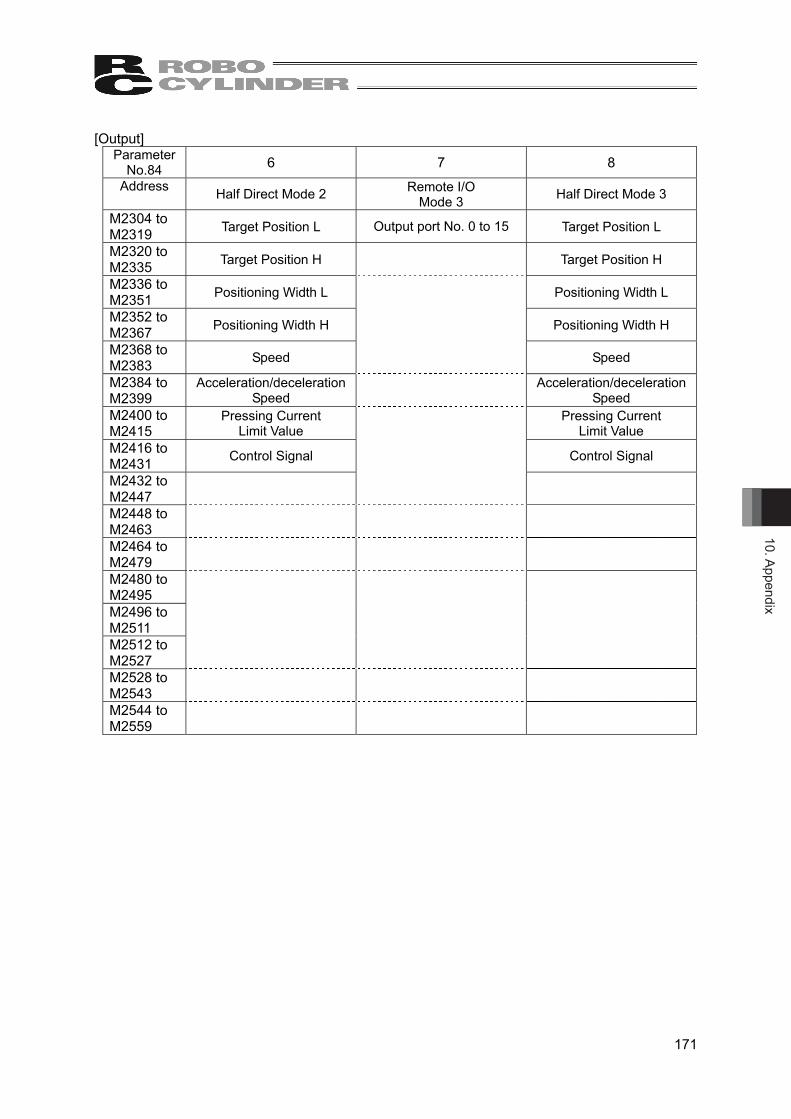
10. Appendix
171
[Output] Parameter
No.84 6 7 8 Address Half Direct Mode 2 Remote I/O
Mode 3 Half Direct Mode 3
M2304 to M2319 Target Position L Output port No. 0 to 15 Target Position L
M2320 to M2335 Target Position H Target Position H
M2336 to M2351 Positioning Width L Positioning Width L
M2352 to M2367 Positioning Width H Positioning Width H
M2368 to M2383 Speed Speed
M2384 to M2399
Acceleration/deceleration Speed Acceleration/deceleration
Speed M2400 to M2415
Pressing Current Limit Value Pressing Current
Limit Value M2416 to M2431 Control Signal Control Signal
M2432 to M2447
M2448 to M2463
M2464 to M2479
M2480 to M2495
M2496 to M2511
M2512 to M2527
M2528 to M2543
M2544 to M2559
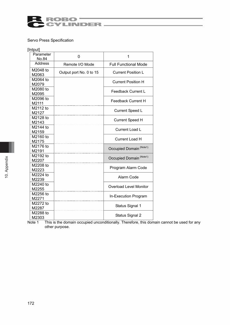
10. A
ppen
dix
172
Servo Press Specification [Intput]
Parameter No.84 0 1
Address Remote I/O Mode Full Functional Mode M2048 to M2063 Output port No. 0 to 15 Current Position L
M2064 to M2079 Current Position H
M2080 to M2095 Feedback Current L
M2096 to M2111 Feedback Current H
M2112 to M2127 Current Speed L
M2128 to M2143 Current Speed H
M2144 to M2159 Current Load L
M2160 to M2175 Current Load H
M2176 to M2191 Occupied Domain (Note1)
M2192 to M2207 Occupied Domain (Note1)
M2208 to M2223 Program Alarm Code
M2224 to M2239 Alarm Code
M2240 to M2255 Overload Level Monitor
M2256 to M2271 In-Execution Program
M2272 to M2287 Status Signal 1
M2288 to M2303 Status Signal 2
Note 1 This is the domain occupied unconditionally. Therefore, this domain cannot be used for any other purpose.

10. Appendix
173
[Outtput] Parameter
No.84 0 1 Address Remote I/O
Mode Full Functional Mode
M2304 to M2319 Input port No. 0 to 15 Target Position L
M2320 to M2335 Target Position H
M2336 to M2351 Positioning Width L
M2352 to M2367 Positioning Width H
M2368 to M2383 Speed L
M2384 to M2399 Speed H
M2400 to M2415 Occupied Domain (Note1)
M2416 to M2431 Occupied Domain (Note1)
M2432 to M2447 Occupied Domain (Note1)
M2448 to M2463 Occupied Domain (Note1)
M2464 to M2479 Acceleration
M2480 to M2495 Deceleration
M2496 to M2511 Occupied Domain (Note1)
M2512 to M2527 Command Program No.
M2528v M2543 Control Signal 1
M2544 to M2559 Control Signal 2
Note 1 This is the domain occupied unconditionally. Therefore, this domain cannot be used for any other purpose.

10. A
ppen
dix
174
10.6 Error Code List When an arithmetic error in the ladder program is generated, the following arithmetic error codes are written in the special register SD2, and the step numbers of the ladder program of the error generation are written in the special register SD3. Codes 22, 23 and 24 are an error at startup, and will be generated when the power gets turned on or after the ladder program gets transferred. Other codes are an error at execution, and will be generated when the ladder program gets executed.
Code Cause Counteraction 1 Instruction code error Write the program again. 2 The label that is specified in the JE, JMP or CALL
(P) instruction does not exist. Change the specified label or create a label that is specified.
L7 was called by the CALL (P) instruction (when an index is used).
Correct the ladder program so that L7 is not specified by the CALL (P) instruction.
3 After the CALL (P) was executed, the END (ENDS) instruction was executed prior to the RET instruction.
Correct the ladder program so that the RET instruction is executed before the JMP instruction is used to exit the subroutine.
The RET instruction was executed prior to the CALL (P) instruction.
Correct the ladder program so that the CALL (P) instruction is executed prior to the RET instruction.
After the FOR instruction was executed, the END (ENDS) instruction was executed prior to the NEXT instruction.
Correct the ladder program so that the FOR and NEXT instructions are used in a pair. Do not exit a FOR to NEXT instruction loop using the JE or JMP instruction.
The NEXT instruction was executed prior to the FOR instruction.
Correct the ladder program so that the FOR and NEXT instructions are used in a pair. Do not exit a FOR to NEXT instruction loop using the JE or JMP instruction.
The number of FOR instructions and the number of NEXT instructions do not match.
Correct the ladder program so that the FOR and NEXT instructions are used in a pair.
The BREAK instruction was executed other than between the FOR and NEXT instructions.
Use the BREAK instruction between the FOR and NEXT instructions.
4 An access was made to an out-of-range OM whose index value is invalid.
Correct the ladder program so that the OM number is within the range when an index is used.
The transfer range of the MCPY (P) or MSET (P) instruction exceeds that of the corresponding OM.
Correct the ladder program so that the OM number is within the range
When the FIFW (P) instruction was executed, the start number + the value of the pointer of the FIFO table exceeds the range of the corresponding OM.
Correct the ladder program so that the OM number is within the range.
5 For ENCO instruction, all data in 2n bits from S are 0. Correct the ladder program so that the correct values are set in the OM specified by S and the subsequent OMs.
Although the value of the pointer is 0, the FIFR (P) instruction was executed.
Correct the ladder program so that the value of the pointer is set correctly.
7 BCD and BIN conversion data error Set a value that can be converted into a BCD or BIN value.
8 Division by zero Correct the ladder program so that the divisor is not 0.
11 The 9th nesting level was executed for the CALL (P) to RET instructions.
Correct the ladder program so that 8 or less nesting levels are used with the CALL (P) to RET instructions.
The 6th nesting level was executed for the FOR to NEXT instructions.
Correct the ladder program so that 5 or less nesting levels are used with the FOR to NEXT instructions.
21 Failed to execute the DFC instruction. Create a correct user function for the DFC instruction.
22 Positioning command was made at 256 points or more on one axis.
Make the number of positioning command use 255 points or less on one axis.

10. Appendix
175
Code Cause Counteraction 23 An inappropriate value was set in S1 of positioning
command. • Number from -32768 to 0 is set as constant • OM other than D is set • D indicated as Index is set • D indicated with long word is set
• Use either a constant or D. • Set a constant from the range from 1 to maximum
position number. • Do not attempt to use IX. • Do not attempt to indicate a long word.
24 An inappropriate value was set in S2 of positioning command. • Value other than M is set • M indicated as Index is set • M indicated multiple bits is set • M used in OUT Command is set • M used for another positioning command is set
• Do not attempt to use any bit OM other than M. • Do not attempt to use IX. • Do not attempt to indicate several bits. • Avoid duplication with M used for another position
command or OUT Command.
25 The value of D set in S1 of a positioning command was 0 or less or exceeded the maximum position number when the positioning command was executed.
• Set the value of D from the range from 1 to the maximum position number when executing the position command.
26 Positioning command was executed before executing the axis control command or with the operation mode setting being inappropriate.
Subscribe the axis control command in the ladder program, set the operation mode setting to either 1, 2, 3 or 5 and execute it with always ON.
27 Positioning command was executed with S2 of the axis control command set to a value other than 1, 2, 3 or 5 (operation mode other than Positioner 1, 2, 3 or 5).
Set S2 of the axis control command to either 1, 2, 3 or 5.
28 Positioning command was executed with the home-return operation incomplete.
Complete the home-return operation before turning ON the contact point of positioning command.
99 WDT Error. Check if there is no infinite loop and correct the ladder program.

10. A
ppen
dix
176
10.7 Basic Positioning Sequence (Example) 10.7.1 Outline The diagram below shows an example for a sequence to execute an operation on the operation box, with one axis (Axis No. 0), among three positions.
Start
Operation Box : Emergency stop cancel
Servo ON
Operation Box : Home Return
Home-Return Operation
Operation Box : RC Start
Move from Position No. 1 to Position No. 2
Move from Position No. 2 to Position No. 3
Move from Position No. 3 to Position No. 1
(Note) If home return is not executed, have it executed before the operation to move to Position No. 1 for the first time.
Position No.2
Position No.1
Position No.3
Position No.2
Position No.3
Position No.1
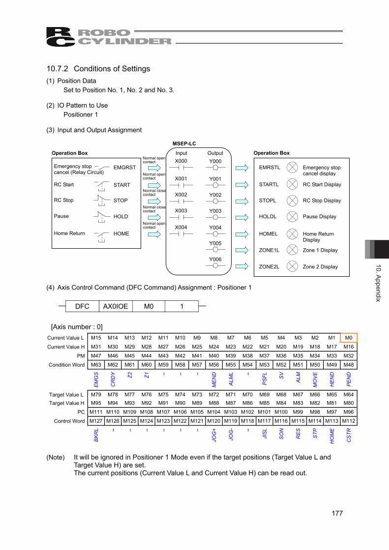
10. Appendix
177
Y000
Y005
Y006
Y001
Y002
Y003
Y004
10.7.2 Conditions of Settings (1) Position Data
Set to Position No. 1, No. 2 and No. 3. (2) IO Pattern to Use
Positioner 1 (3) Input and Output Assignment (4) Axis Control Command (DFC Command) Assignment : Positioner 1
[Axis number : 0] Current Value L M15 M14 M13 M12 M11 M10 M9 M8 M7 M6 M5 M4 M3 M2 M1 M0
Current Value H M31 M30 M29 M28 M27 M26 M25 M24 M23 M22 M21 M20 M19 M18 M17 M16
PM M47 M46 M45 M44 M43 M42 M41 M40 M39 M38 M37 M36 M35 M34 M33 M32
Condition Word M63 M62 M61 M60 M59 M58 M57 M56 M55 M54 M53 M52 M51 M50 M49 M48
EM
GS
CR
DY
Z2
Z1 -
-
-
ME
ND
ALM
L
-
PS
FL
SV
ALM
MO
VE
HE
ND
PE
ND
Target Value L M79 M78 M77 M76 M75 M74 M73 M72 M71 M70 M69 M68 M67 M66 M65 M64 Target Value H M95 M94 M93 M92 M91 M90 M89 M88 M87 M86 M85 M84 M83 M82 M81 M80
PC M111 M110 M109 M108 M107 M106 M105 M104 M103 M102 M101 M100 M99 M98 M97 M96
Control Word M127 M126 M125 M124 M123 M122 M121 M120 M119 M118 M117 M116 M115 M114 M113 M112
BK
RL
-
-
-
-
-
-
JOG
+
JOG
-
-
JIS
L
SO
N
RE
S
STP
HO
ME
CS
TR
(Note) It will be ignored in Positioner 1 Mode even if the target positions (Target Value L and
Target Value H) are set. The current positions (Current Value L and Current Value H) can be read out.
M0 AX0IOE DFC 1
EMGRST
START
STOP
HOLD
HOME
Emergency stop cancel (Relay Circuit)
RC Start
RC Stop
Pause
Home Return
Operation Box
EMRSTL Emergency stop cancel display
RC Start Display STARTL
STOPL
HOLDL
ZONE1L
HOMEL
ZONE2L
RC Stop Display
Pause Display
Home Return Display
Zone 1 Display
Zone 2 Display
Operation Box Input Output X000
X001
X002
X003
X004
MSEP-LC
Normal open contact
Normal open contact
Normal close contact
Normal close contact
Normal open contact

10. A
ppen
dix
178
(5) Supportive Relays
Internal Memories (M) Comment
M150 AUX1 Pause Aux.1 M151 AUX2 Pause Aux.2 M152 AUX3 Pause Cancel M153 AUX4 Completed Position No.1 M154 AUX5 Completed Position No.2 M155 AUX6 Completed Position No.3 M156 AUX7 Position 1 Positioning Start Pulse M157 AUX8 Auxiliary Position 1 Positioning Start Pulse M158 AUX9 Auxiliary Position 1 Positioning Start M159 AUX10 Position 1 Positioning Start Check M160 AUX11 Position 1 positioning confirmation M161 AUX12 Auxiliary Position 2 Positioning Start M162 AUX13 Position 2 Positioning Start Check M163 AUX14 Position 2 positioning confirmation M164 AUX15 Auxiliary Position 3 Positioning Start M165 AUX16 Position 3 Positioning Start Check M166 AUX17 Position 3 positioning confirmation M167 AUX18 Position 1 set M168 AUX19 Position 2 set M169 AUX20 Position 3 set

10. Appendix
179
Axis control command always on
Always on
10.7.3 Ladder Program [1] Axis control command (DFC Command) always ON
Keep the axis control command (DFC Command) always ON. [2] Servo ON (Emergency Stop) Circuit
1) The emergency stop release circuit equipped in the operation BOX is assumed that it is a self-holding circuit. It turns ON the “servo-on” signal once the emergency stop gets in released condition.
2) Then if the emergency stop release state continues, the operation ready complete signal is turned ON to go on the “Emergency stop release” lamp, which indicates that the actuator can be operated.
[3] Operation and Stop Circuit
Operation and Stop CircuitRC Start Display
RC Stop Display
STARTRC Start
PENDPointPositioningCompletion
STARTLRC Start Display
STARTLRC Start Display
EMGRSTEmergency Stop Cancel
HOMEHome Return
STOPRC Stop
STOPLRC Stop Display
STARTLRC Start Display
Stop Command
Output Driver board
Input Driver board
Start Stop
Start
Start
Start
Stop
Emergency stop cancel
It is used as the continuous operation command.
Servo ON (Emergency Stop) CircuitServo ON
Emergency StopEMGRST Cancel Display
EMGRSTEmergency Stop Cancel
EMGRSTEmergency Stop Cancel
SVOperationPreparation End
Input Driver board
Output Driver board
Emergency stop cancel
Emergency stop cancel
This circuit may only consist of SV. However, to go off the emergency stop release lamp immediately at external emergency stop, it also includes EMGRST because EMGRST not only goes on the lamp but also performs the emergency stop processing of other circuits.
(Interlock) Prohibits start during home return.
Step number: It shows the number of steps on LC.
Once the servo ON the controller turns ON, PEND turns ON to conduct a positioning to the current position. Therefore, it is used to judge whether operation is available (to confirm READY condition ON controller).
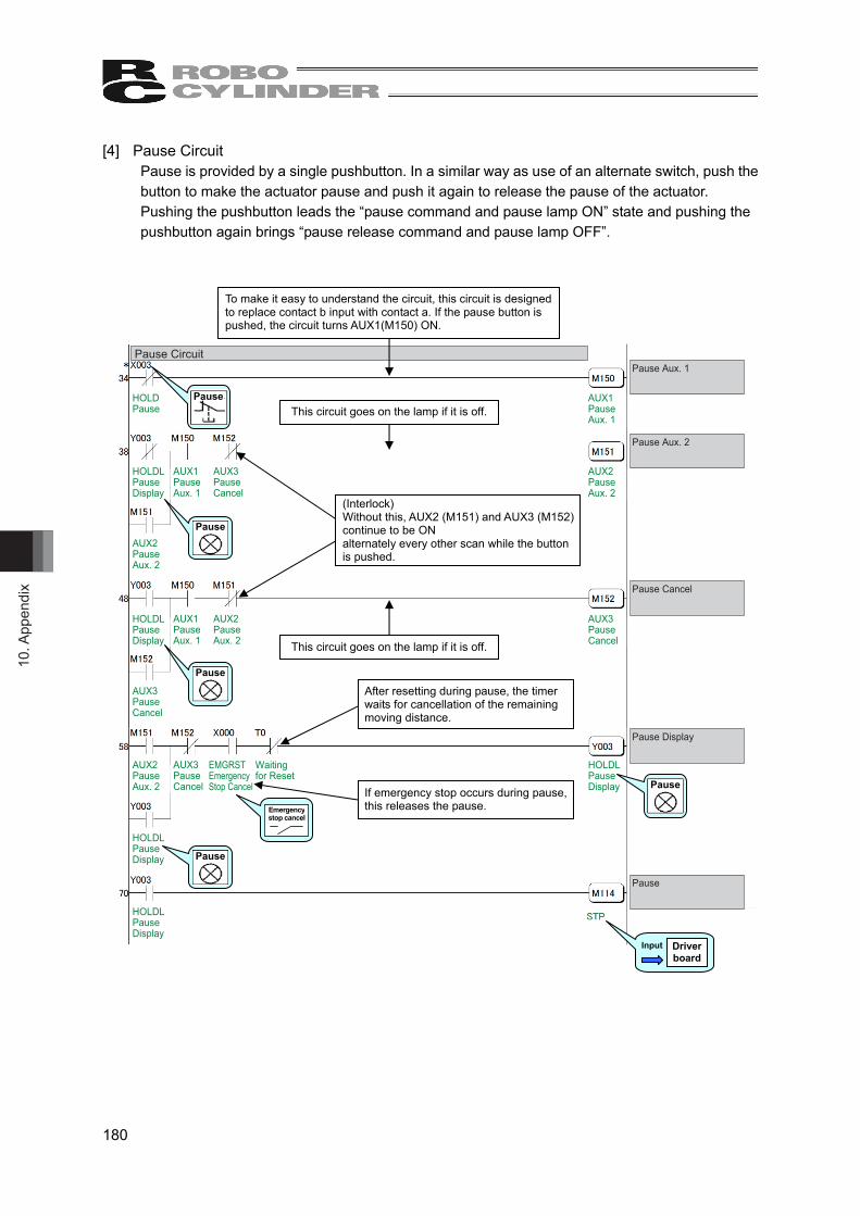
10. A
ppen
dix
180
[4] Pause Circuit Pause is provided by a single pushbutton. In a similar way as use of an alternate switch, push the button to make the actuator pause and push it again to release the pause of the actuator. Pushing the pushbutton leads the “pause command and pause lamp ON” state and pushing the pushbutton again brings “pause release command and pause lamp OFF”.
Pause Circuit
HOLDPause
HOLDLPauseDisplay
HOLDLPauseDisplay
HOLDLPauseDisplay
HOLDLPauseDisplay
AUX2PauseAux. 2
AUX2PauseAux. 2
AUX3PauseCancel
AUX1PauseAux. 1
AUX3PauseCancel
AUX2PauseAux. 2
AUX1PauseAux. 1
AUX3PauseCancel
EMGRSTEmergencyStop Cancel
Waitingfor Reset
HOLDLPauseDisplay
AUX3PauseCancel
AUX1PauseAux. 1
AUX2PauseAux. 2
Pause Aux. 1
Pause Aux. 2
Pause Cancel
Pause Display
Pause
Input Driver board
Pause
Pause
Pause
Pause
Pause
Emergency stop cancel
If emergency stop occurs during pause, this releases the pause.
To make it easy to understand the circuit, this circuit is designed to replace contact b input with contact a. If the pause button is pushed, the circuit turns AUX1(M150) ON.
(Interlock) Without this, AUX2 (M151) and AUX3 (M152) continue to be ON alternately every other scan while the button is pushed.
After resetting during pause, the timer waits for cancellation of the remaining moving distance.
This circuit goes on the lamp if it is off.
This circuit goes on the lamp if it is off.

10. Appendix
181
[5] Reset Circuit If the “Stop” button on the operation BOX is pushed during pause, the “Reset” signal is turned ON and the remaining moving distance is cancelled. In addition, this operation releases the pause. (It is because the pause is not required with no remaining moving distance.)
Reset Circuit
RESReset
HOLDLPauseDisplay
STOPLRC StopDisplay
ALMAlarm
RESReset
Waiting for Reset
Waiting for Reset
Reset
(Interlock) Reset input is disabled because alarm reset is generated while an alarm occurs.
Output Driver board
Input Driver board
Input Driver board
Stop Pause
Due to no reset complete signal, pause state is not cancelled until reset processing is completed.
After 200 ms from reset input, the “Pause” lamp goes off and the “Pause” signal is turned OFF. Thus, the reset signal remains ON for 200ms.

10. A
ppen
dix
182
[6] Home Return Circuit
Home Return Circuit
HOMESHomeReturn
HENDHome ReturnComplete
PENDPointPositioningCompletion
STARTLRC StartDisplay
HOMEHomeReturn
HOMEHomeReturn
Home ReturnDispalyAux. 2
Home ReturnDispalyAux. 1
Home ReturnDispalyAux. 1
HENDHome ReturnComplete
Home ReturnDispalyAux. 2
HOMELHome ReturnDispaly
Home ReturnDispalyAux. 1
HOMEHomeReturn
Home Return
Home Return Aux. 1
Home Return Aux. 2
Home Return Dispaly
Output Driver board
Input Driver board
Output Driver board
Input Driver board
Output Driver board
Input Driver board
Start Home Return
Similar to the operation circuit, this is used to determine whether the controller can be operated. (Confirmation of READY status of controller)
(Interlock) Turns the “Home return” signal OFF at completion of home return. It is set as it would not be able to home return again after the home return operation is complete unless “Home Return Complete” signal turns OFF.
(Interlock) This disables home return during continuous operation.
Home-Return Lamp Switching Circuit
While the “Home return” signal is ON, these repeat ON/OFF at intervals of 200 ms.
The “Home return” lamp blinks during home return and goes on at the “Home return complete” signal.

10. Appendix
183
[7] Decode Circuit of Positioning Complete Position No. The decode circuit converts the binary data of positioning complete position No. into the corresponding bit data.
[8] Actuator Start Circuit
If the “Start” switch on the operation BOX is pushed, the lamp of the “Start” pushbutton switch described in [3] Operation and Stop Circuit goes on and, at the same time, the actuator starts successive positioning of position No. 1→2→3→1→2•••. The circuit below is intended for the activation.
Actuator Start Circuit
STARTLRC Start Display
AUX8 Aux. P1Positioning Start Pulse
STARTLRC Start Display
AUX7 P1PositioningStart Pulse
AUX8 Aux. P1Positioning Start Pulse
AUX7 P1PositioningStart Pulse
AUX8 Aux. P1Positioning Start Pulse
Position 1 PositioningStart Pulse
Aux. Position 1Positioning Start Pulse
Because the operation signal remains ON until the stop button is pushed, pulsed start signal is generated so that the circuit for moving to the first position No.1 may not remain ON. operates next circuit. 1
1
Start
Start
Decode Circuit of Positioning Complete Position No.
Point PositioningCompletion
AUX4 Completed Position No.1
AUX5 Completed Position No.2
AUX6 Completed Position No.3
PM1CompletedPosition 1
PM2CompletedPosition 2
PM4CompletedPosition 4
PointPositioningCompletion
PM1CompletedPosition 1
PM2CompletedPosition 2
PM4CompletedPosition 4
PointPositioningCompletion
PM1CompletedPosition 1
PM2CompletedPosition 2
PM4CompletedPosition 4
PointPositioningCompletion
PENDPointPositioningCompletion
Point Positioning Completion
Completed Position No.1
Completed Position No.2
Completed Position No.3
Output Driver board This is the timer to prevent the code reading
error since the scanning is held independently by LC and driver board.

10. A
ppen
dix
184
[9] Position 1 Operation Circuit The main circuit is designed to process and manage signals “Startup” → “Moving” → “Positioning completion” to move the actuator to position No.1.
Circuit is designed to start positioning to position No.1 again after positioning to position No.3 is completed.
If the “Start” lamp goes off, the operation circuit is reset entirely. When the “Stop” button is pushed, the actuator will stop at completion of the operation being executed. At emergency stop, the actuator is stopped immediately (which is the function of MSEP-LC).
10
Position 1 Operation Circuit
AUX9Auxiliary Start 1
AUX7 P1PositioningStart Pulse
PENDPointPositioningCompletion
AUX17 P3PositioningComplete
AUX6CompletedPosition 3
PENDPointPositioningCompletion
AUX9Auxiliary Start 1
AUX10Positioning Confirmation 1
AUX11 P1PositioningComplete
AUX4CompletedPosition 1
AUX10Positioning Confirmation 1
STARTLRC StartDisplay
AUX12Auxiliary Start 2
STARTLRC StartDisplay
AUX11 P1PositioningComplete
STARTLRC StartDisplay
AUX10Positioning Confirmation 1
AUX9Auxiliary Start 1
AUX10Positioning Confirmation 1
AUX11 P1PositioningComplete
Auxiliary Position 1Positioning Start
Position 1Positioning Start Check
Position 1Positioning Complete
If is not pulsed, is turned ON when is reset with turned ON.
1 4
2 3
Without home return, positioning to position No.1 takes place after home return.
To position No.2 startup circuit
Because any of startup, moving or completion is set to ON, it is possible to know the state in which the actuator is stopped if it occurs.
If movement is started (PEND is turned OFF), the start circuit is turned OFF.
If movement is completed, the moving circuit is turned OFF.
Turned OFF at startup of next positioning to position No.2.
10
3
2
1 Output Driver
board
Output Driver board
3
4
2
Moving
Startup
Complete
Start
Start
Start
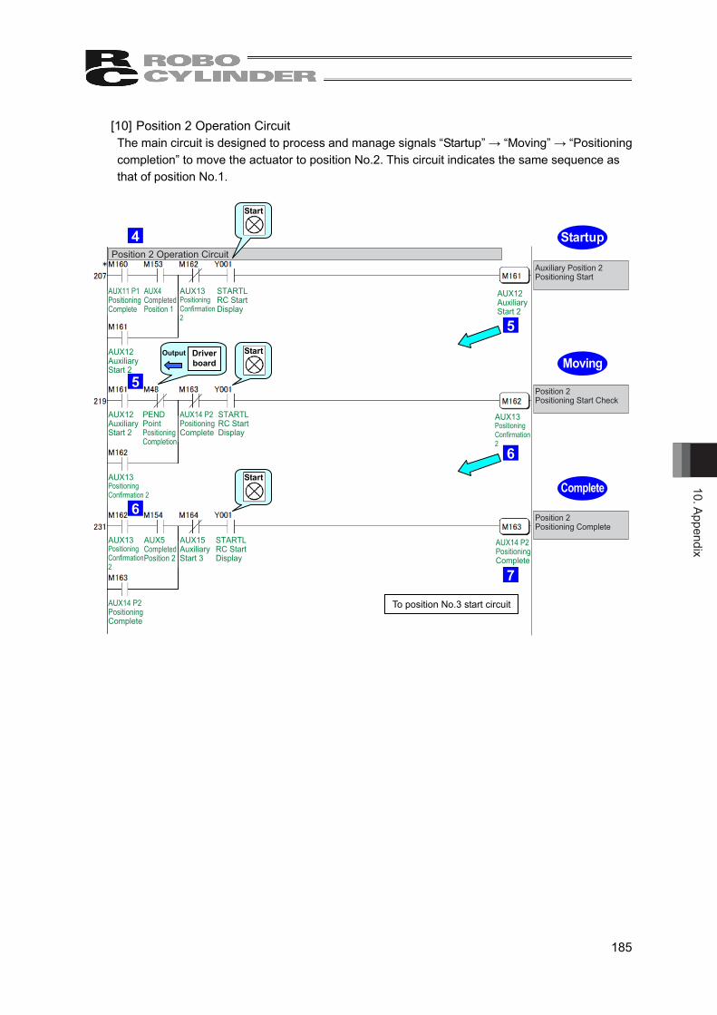
10. Appendix
185
[10] Position 2 Operation Circuit The main circuit is designed to process and manage signals “Startup” → “Moving” → “Positioning completion” to move the actuator to position No.2. This circuit indicates the same sequence as that of position No.1.
Position 2 Operation Circuit
AUX12Auxiliary Start 2
STARTLRC Start Display
AUX13Positioning Confirmation2
AUX4CompletedPosition 1
AUX11 P1PositioningComplete
AUX12Auxiliary Start 2
PENDPointPositioningCompletion
STARTLRC Start Display
AUX14 P2PositioningComplete
AUX13Positioning Confirmation 2
AUX13Positioning Confirmation2
STARTLRC Start Display
AUX15Auxiliary Start 3
AUX5CompletedPosition 2
AUX14 P2PositioningComplete
AUX12Auxiliary Start 2
AUX13Positioning Confirmation2
AUX14 P2PositioningComplete
Auxiliary Position 2Positioning Start
Position 2Positioning Start Check
Position 2 Positioning Complete
To position No.3 start circuit
Output Driver board
6
5
4
6
Moving
Startup
Complete
7
5
Start
Start
Start
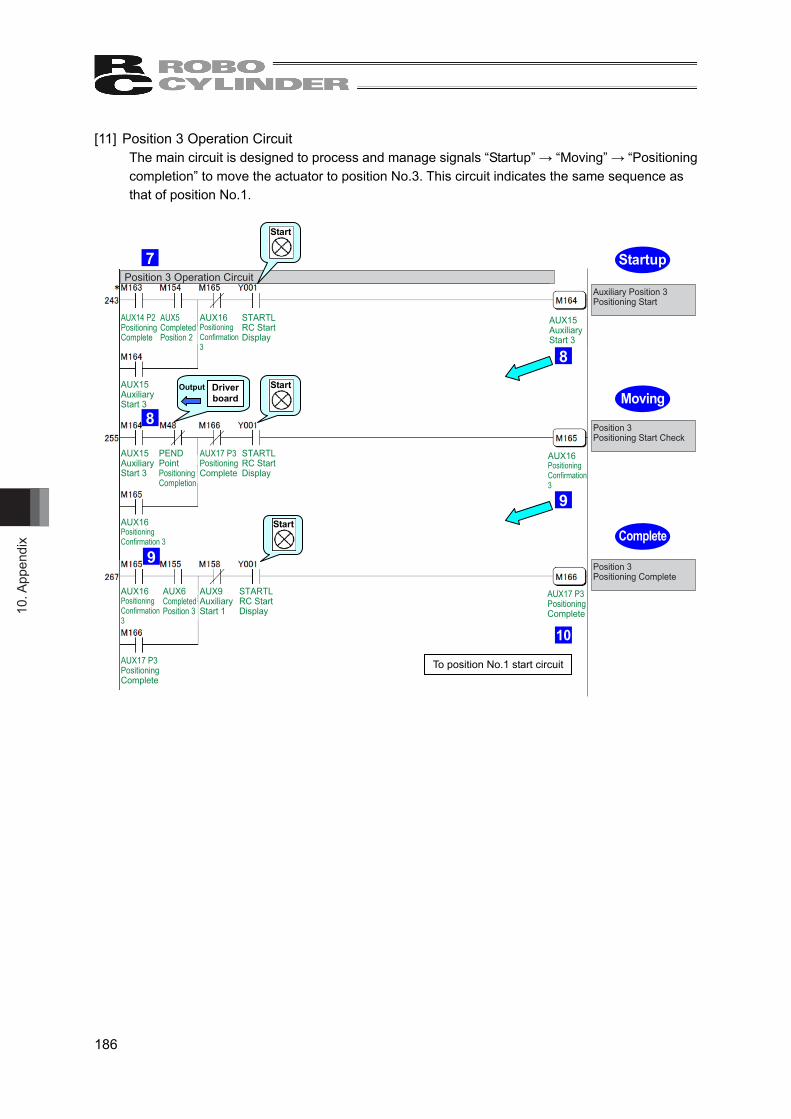
10. A
ppen
dix
186
[11] Position 3 Operation Circuit The main circuit is designed to process and manage signals “Startup” → “Moving” → “Positioning completion” to move the actuator to position No.3. This circuit indicates the same sequence as that of position No.1.
Position 3 Operation Circuit
AUX15Auxiliary Start 3
STARTLRC Start Display
AUX16Positioning Confirmation3
AUX5CompletedPosition 2
AUX14 P2PositioningComplete
AUX15Auxiliary Start 3
PENDPointPositioningCompletion
STARTLRC Start Display
AUX17 P3PositioningComplete
AUX16Positioning Confirmation 3
AUX16Positioning Confirmation3
STARTLRC Start Display
AUX9Auxiliary Start 1
AUX6CompletedPosition 3
AUX17 P3PositioningComplete
AUX15Auxiliary Start 3
AUX16Positioning Confirmation3
AUX17 P3PositioningComplete
Auxiliary Position 3Positioning Start
Position 3Positioning Start Check
Position 3 Positioning Complete
To position No.1 start circuit
Output Driver board
9
8
7
9
Moving
Startup
Complete
10
8
Start
Start
Start

10. Appendix
187
[12] Commanded Position No. Output Ready Circuit The ready circuit is designed to hold start command and output commanded position No. in the binary code. Interlock is taken so that position No. command may not be specified incorrectly.
Once a moving command to a position is issued, any of circuits A, B and C is turned ON to remember it unless a moving command to another position is issued. The operation circuit is cancelled by a stop command such as an emergency stop command. However, the circuit remembers the positions to which the actuator moved and the positions at which the actuator stopped until the cancellation. Such sequence design is also intended to cope with errors occurred and helpful to find the causes of the errors from circuit status, stop position inconsistency and other conditions.
Taking interlock in both commands and results is usual means in circuit design to prevent results from being ON simultaneously. For example, if both SOLs in a solenoid valve of double SOL type are turned ON simultaneously, the coils are burned instantly. In another case, LC executes a program in descending order but operations are not always done in the order. If you create a sequence program taking operation order into account, circuit change and/or addition due to debugging and specification change may cause the operation order to be modified without intention. Take interlock securely.
Commanded Position No. Output Ready Circuit
AUX9Auxiliary Start 1
AUX15Auxiliary Start 3
AUX19Position 2Set
AUX20Position 3Set
AUX12Auxiliary Start 2
AUX12Auxiliary Start 2
AUX15Auxiliary Start 3
AUX18Position 1Set
AUX20Position 3Set
AUX9Auxiliary Start 1
AUX18Position 1Set
AUX19Position 2Set
AUX15Auxiliary Start 3
AUX12Auxiliary Start 2
AUX18Position 1Set
AUX19Position 2Set
AUX9Auxiliary Start 1
AUX20Position 3Set
Position 1 Set
Position 2 Set
Position 3 Set
AUX18Position 1Set
AUX19Position 2Set
AUX20Position 3Set
Position No.1, 2, or 3 set relay
Position No.1, 2, or 3 start command
8
5
2
A
B
C
To commanded position No. output circuit
To commanded position No. output circuit
To commanded position No. output circuit
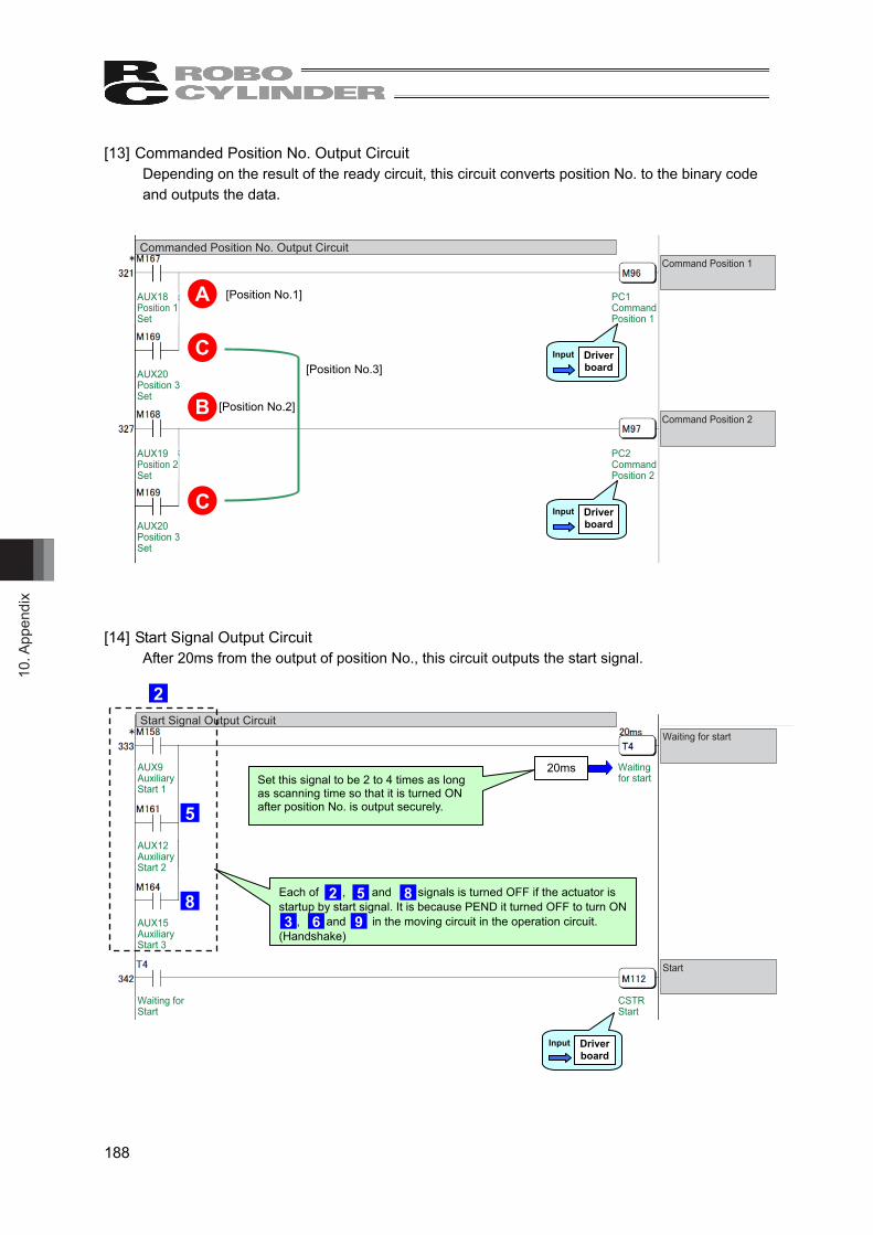
10. A
ppen
dix
188
[13] Commanded Position No. Output Circuit Depending on the result of the ready circuit, this circuit converts position No. to the binary code and outputs the data.
[14] Start Signal Output Circuit
After 20ms from the output of position No., this circuit outputs the start signal.
Commanded Position No. Output Circuit
Command Position 2
Command Position 1
AUX18Position 1Set
AUX20Position 3Set
AUX19Position 2Set
AUX20Position 3Set
PC1Command Position 1
PC2Command Position 2
[Position No.1]
[Position No.2]
[Position No.3]
A
B
C
C
Input Driver board
Input Driver board
Start Signal Output CircuitWaiting for start
Start
Waiting for Start
AUX9Auxiliary Start 1
AUX12Auxiliary Start 2
AUX15Auxiliary Start 3
Waiting for start
CSTRStart
Set this signal to be 2 to 4 times as long as scanning time so that it is turned ON after position No. is output securely.
Input Driver board
20ms
2
5
8 Each of , and signals is turned OFF if the actuator is startup by start signal. It is because PEND it turned OFF to turn ON , and in the moving circuit in the operation circuit. (Handshake)
2 5 8
3 6 9

10. Appendix
189
[15] Other Display Circuits (Zone 1, Zone 2)
Other Display Circuits (Zone 1, Zone 2)Zone 1 Display
Zone 2 Display
ZONE1
ZONE2
ZONE1LZone 1 Display
ZONE2LZone 2 Display
Output Driver board
Zone 1
Zone 2 Output Driver board
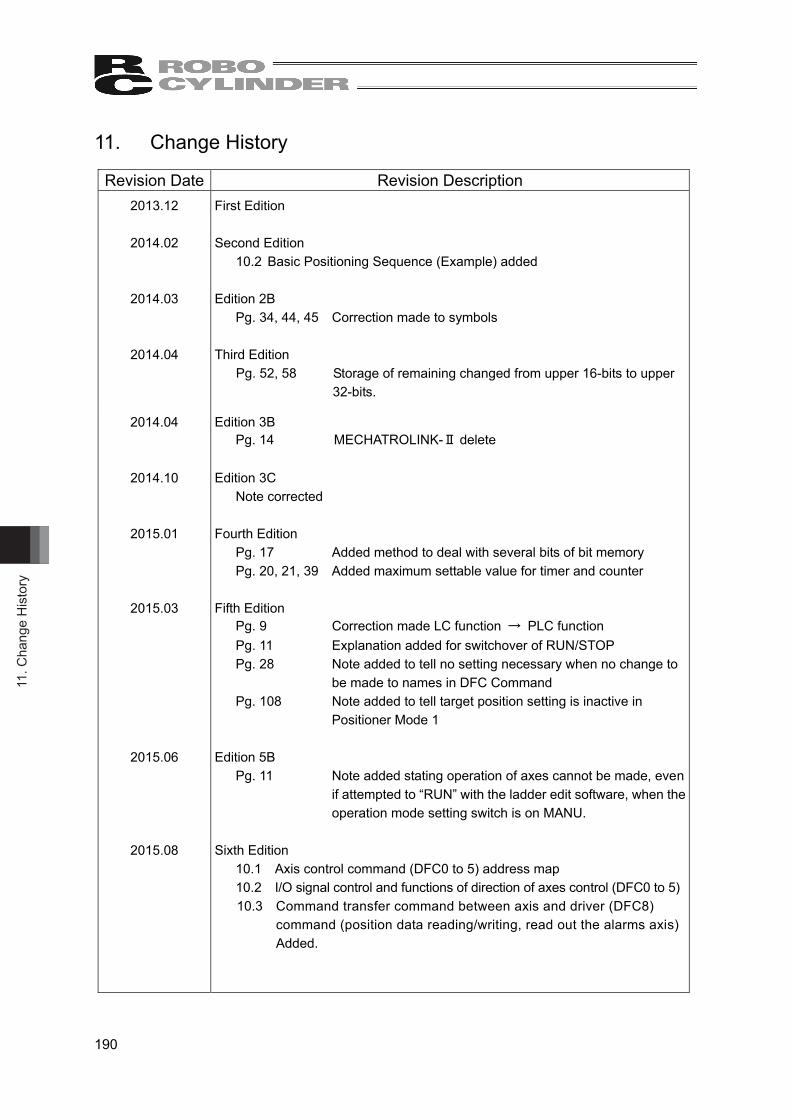
11. C
hang
e H
isto
ry
190
11. Change History
Revision Date Revision Description 2013.12
2014.02
2014.03
2014.04
First Edition Second Edition
10.2 Basic Positioning Sequence (Example) added
Edition 2B Pg. 34, 44, 45 Correction made to symbols
Third Edition Pg. 52, 58 Storage of remaining changed from upper 16-bits to upper
32-bits.
2014.04
2014.10
2015.01
2015.03
2015.06
2015.08
Edition 3B Pg. 14 MECHATROLINK-Ⅱdelete
Edition 3C Note corrected
Fourth Edition Pg. 17 Added method to deal with several bits of bit memory Pg. 20, 21, 39 Added maximum settable value for timer and counter
Fifth Edition Pg. 9 Correction made LC function → PLC function Pg. 11 Explanation added for switchover of RUN/STOP Pg. 28 Note added to tell no setting necessary when no change to
be made to names in DFC Command Pg. 108 Note added to tell target position setting is inactive in
Positioner Mode 1
Edition 5B Pg. 11 Note added stating operation of axes cannot be made, even
if attempted to “RUN” with the ladder edit software, when the operation mode setting switch is on MANU.
Sixth Edition
10.1 Axis control command (DFC0 to 5) address map 10.2 I/O signal control and functions of direction of axes control (DFC0 to 5) 10.3 Command transfer command between axis and driver (DFC8)
command (position data reading/writing, read out the alarms axis) Added.
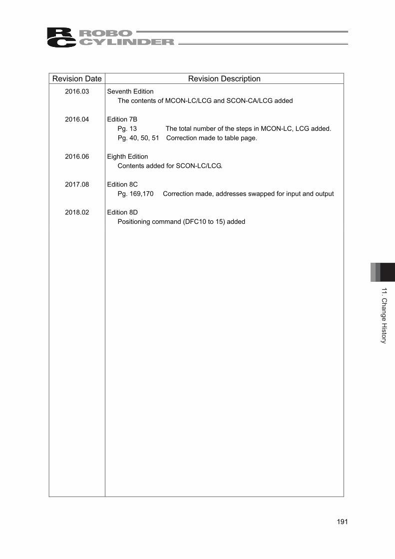
11. Change H
istory
191
Revision Date Revision Description
2016.03
2016.04
2016.06
2017.08
2018.02
Seventh Edition The contents of MCON-LC/LCG and SCON-CA/LCG added
Edition 7B
Pg. 13 The total number of the steps in MCON-LC, LCG added. Pg. 40, 50, 51 Correction made to table page.
Eighth Edition Contents added for SCON-LC/LCG.
Edition 8C Pg. 169,170 Correction made, addresses swapped for input and output
Edition 8D Positioning command (DFC10 to 15) added


Manual No.: ME0329-8D (February 2018)
The information contained in this document is subject to change without notice for purposes of product improvement.Copyright © 2018. Feb. IAI Corporation. All rights reserved.
18.02.000
Head Office: 577-1 Obane Shimizu-KU Shizuoka City Shizuoka 424-0103, JapanTEL +81-54-364-5105 FAX +81-54-364-2589
website: www.iai-robot.co.jp/
Ober der Röth 4, D-65824 Schwalbach am Taunus, GermanyTEL 06196-88950 FAX 06196-889524
SHANGHAI JIAHUA BUSINESS CENTER A8-303, 808, Hongqiao Rd. Shanghai 200030, ChinaTEL 021-6448-4753 FAX 021-6448-3992
website: www.iai-robot.com
Technical Support available in USA, Europe and China
Head Office: 2690 W. 237th Street, Torrance, CA 90505TEL (310) 891-6015 FAX (310) 891-0815
Chicago Office: 110 East State Parkway, Schaumburg, IL 60173TEL(847) 908-1400 FAX (847) 908-1399
TEL (678) 354-9470 FAX (678) 354-9471website: www.intelligentactuator.com
Atlanta Office: 1220 Kennestone Circle, Suite 108, Marietta, GA 30066
825, PhairojKijja Tower 12th Floor, Bangna-Trad RD., Bangna, Bangna, Bangkok 10260, ThailandTEL +66-2-361-4458 FAX +66-2-361-4456