mcac-htsm-2012-04 r410a full dc inverter mini vrf · pdf filepart 5 electric and control...
TRANSCRIPT

MCAC-HTSM-2012-04 R410a Full DC Inverter Mini VRF
Electric and Control System 89
Part 5
Electric and Control System
1. Electric System ............................................................................... 90
1.1 Wiring Diagrams and Field Wiring ............................................ 90
1.2 Description of Main Control Board of Outdoor unit ................ 90
1.3 SW1 Query Instruction ............................................................... 91
1.4 Description of Main Control Board of Indoor unit ................... 92
1.5 Electric Wiring Installations ....................................................... 95
2. Control System ................................................................................... 99
2.1 Control System Introduction ..................................................... 99
2.2 Wireless Remote Controller ..................................................... 105
2.3 Wired Controller........................................................................ 116
2.4 Central Control Monitor ........................................................... 125
2.5 Network Control System .......................................................... 176
2.6 Other Accessory ....................................................................... 181

R410a Full DC Inverter Mini VRF MCAC-HTSM-2012-04
90 Electric and Control System
1. Electric System
1.1 Wiring Diagrams and Field Wiring
Wiring diagrams and field wiring please refer to ―Wiring Diagrams and field wiring‖ of ―Part 2 Specification & Performance‖
1.2 Description of Main Control Board of Outdoor unit

MCAC-HTSM-2012-04 R410a Full DC Inverter Mini VRF
Electric and Control System 91
Dial codes definition
SW3 definition
SW3
1 ON Obtain network address automatically
OFF Obtain network address manually
2 ON Revocation indoor unit network address
OFF /
Explanation of main board
No. Content No. Content
1 Port for inverter module voltage inspection 10 Input current of the mutual inductor at the inverter
compressor
2 Mutual inductor for compressor DC current 11 Reserve
3 Activation port of inverter module 12 SW3 net address code automatically
4 Port of DC fan 1 13 Internet group control of indoor units
5 Port of DC fan 2 14 Communication between indoor and outdoor units
6 Loading output terminal 15 Inspection port for outdoor ambient temp. and
condenser coil temp.
7 Input for N phase power supply 16 Air discharge temp. sensed port at the compressor
8 Power supply for relay 17 Input port for system pressure inspection
9 EXV activation port 18 Input port for power supply of the main control board
1.3 SW1 Query Instruction
No. Display content Note No. Display content Remark
0 Normal display ---- 9 Opening degree of PMV ----
1 Running mode 0-OFF;2-Cooling;3-Heating; 4-Force Cooling
10 Actual current value ----
2 Fan speed 0-OFF 11 AD actual value of voltage ----
3 Capacity requirement of indoor unit
---- 12 T2 average temperature ----
4. Capacity requirement of master unit after correction
---- 13 Quantity of indoor units ----
5 T3 pipe temperature Actual value 14 Running quantity of indoor units ----
6 T4 pipe temperature Actual value 15 The latest malfunction or protection code
----
7 T5 discharge temperature
If more than one hundred, only display hundred s’ and tens digits.
16 ―- -‖ displays
----
8 Surface temperature of the cooling fin
----

R410a Full DC Inverter Mini VRF MCAC-HTSM-2012-04
92 Electric and Control System
Remark:
1) Normal display: Display frequency of compressor when capacity needing.
2) Running mode: 0──OFF; 2──COOLING; 3──HEATING; 4──FORCED COOLING.
3) Fan speed: 0──OFF; 1~7──Speed increasing in turn.
4) SW1: Forced cooling button.
5) SW2: Query button.
1.4 Description of Main Control Board of Indoor unit
There are two shapes of main control board that used to all types of indoor unit matching with V4+
outdoor unit.
Shape 1

MCAC-HTSM-2012-04 R410a Full DC Inverter Mini VRF
Electric and Control System 93
Shape 2
Dial codes definition 0/1 definition
Means 0
Means 1
SW1 definition
1 means factory test mode 0 means default auto addressing mode
1 means DC fan is chosen 0 means AC fan is chosen
00 means DC fan static pressure is 0 (reserved)
01 means DC fan static pressure is 1 (reserved)
10 means DC fan static pressure is 2 (reserved)
11 means DC fan static pressure is 3 (reserved)
SW2 definition
00 means shutting down the unit to
stop cold air at 15℃
01 means shutting down the unit to
stop cold air at 20℃

R410a Full DC Inverter Mini VRF MCAC-HTSM-2012-04
94 Electric and Control System
10 means shutting down the unit to
stop cold air at 24℃
11 means shutting down the unit to
stop cold air at 26℃
00 means the time of stopping fan (when no capacity need) is 4 minutes
01 means the time of stopping fan (when no capacity need) is 8 minutes
10 means the time of stopping fan (when no capacity need) is 12 minutes
11 means the time of stopping fan (when no capacity need) is 16 minutes
SW5 definition
00 means temperature
compensation value is 6℃ under
heating mode
01 means temperature
compensation value is 2℃ under
heating mode
10 means temperature
compensation value is 4℃ under
heating mode
11 means temperature
compensation value is 8℃ under
heating mode
SW6 definition
1 means old display panel 0 means new display panel
Reserved
SW7 definition
Normal configuration
Last unit of the network
J1 J2 definition
Without jumper J1 for auto restart
function
With jumper J1 for non-auto restart
function
reserved
Error code & indication
Error code Lamp indication Content
FE Time LED and run LED flash together Without address when first time power on
H0 4 LED flash together M_Home non-matching
E0 Defrost LED flashes Modes conflict
E1 Timer LED flashes Communicative error between indoor and
outdoor units
E2 Run LED flashes Temperature sensor T1 error
E3 Run LED flashes Temperature sensor T2 error
E4 Run LED flashes Temperature sensor T2B error
E7 Defrost LED flash slowly EEPROM error
Ed Alarm LED flashes slowly Outdoor unit error
EE Alarm LED flash Water level alarm

MCAC-HTSM-2012-04 R410a Full DC Inverter Mini VRF
Electric and Control System 95
Note: Some unit that has digital tube will show the error code when error occurs, others show lamp
indication.
Explanation of main board
No. Content No. Content
1 Power input of transformer 12 Electric expansion valve drive port
2 Power output of transformer 13 Swing motor drive ports
3 Port for remote ON/OFF switch 14 Port for electric auxiliary heater
4 Port for infrared sensor 15 Indoor evaporator outlet pipe temp. detect port
5 Water level switch 16 Indoor ambient and evaporator middle part temp. detect port
6 Port for network module 17 Port for indoor fan motor
7 Port for new display board 18 Reserved
8 Port for old display board 19 Power input port
9 Communication port of X Y E 20 Port for alarm
10 Communication port of P Q E 21 Port for water pump
11 Port for on-line writing program ─
New Added Function—Auto Addressing
1) New Auto-Addressing is just a newly designed indoor-address distributed method which will
automatically be done by outdoor unit, without manual addressing. When the unit is under testing, as
the outdoor and indoor units are powered on simultaneously, the outdoor unit will automatically
distribute different address to every indoor unit in less than 10 minutes.
2) With regarding to the customer’s desire of some kind fixed address or regular addresses for all
indoor units, it can be achieved by wireless remote controller.
1.5 Electric Wiring Installations
1.5.1 Highlights of electrical installation
1) Please separately design the special power of indoor units and outdoor units.
2) The power adopts special circuit, and installs creepage protector and manual switch.
3) The indoor units’ power, creepage protector and manual switch connecting to the same outdoor unit
must be general. All indoor units must be the same circuit, and must simultaneously on or off; otherwise,
system life will seriously effect, and appear the situation not to solve.

R410a Full DC Inverter Mini VRF MCAC-HTSM-2012-04
96 Electric and Control System
4) The communication line between indoor units and outdoor units please use 3 core shielded wiring,
while don’t use the multi core wiring without shielded affect, for the interference is reduced each other
5) Purchased wiring, parts and materials should be in compliance with the local and national regulations.
6) All field wiring construction should be finished by qualified electrician.
7) Air conditioning equipment should be grounded according to the relevant local and national electrical
regulations.
8) Current leakage protection switch should be installed (select current leakage breaker in light of the
1.5-2 times of total loading rated current.)
9) When connecting wiring and wire holder, use cable clamp to fix and make sure no exposure.
10) Refrigerant piping system and wiring system of indoor and outdoor unit belongs to the different
system.
11) Do not connect the power wire to the terminal of signal wire.
12) When power wire is parallel with signal wire, put wires to their own wire tube and remain proper gap
(the current capacity of power wire is: 10A below 300mm, 50A below 500mm).
13) Voltage discrepancy of power wire terminal (side of power transformer) and end voltage (side of unit)
should be less than 2%. If its length could not be shortened, thicken the power wire. Voltage discrepancy
between phases shall not pass 2% rated value and Current discrepancy between highest and lowest
phase should be less than 3% rated value.
1.5.2 Selection of wiring
1. The selection of wiring area shall in accordance with the requirements below:
1) Voltage loss of wire shall meet the requirement of terminal voltage for normal operation and startup.
2) The wiring current-carrying capacity determined by installed method and environment is not less than
the largest current of unit.
3) Conductor shall ensure the stability of movement and heating.
4) The conductor’s smallest sectional area should satisfy the requirement of mechanical strength.
When earth protection line (shortly called PE line) is made of material the same as phase line, the
smallest sectional area of PE line should be in accordance with the regulation below:
Sectional area of core to phase lines(mm²) Smallest sectional area of PE line(mm²)
S≤16 S
16<S≤35 16
S>35 S/2
1.5.3 Distribution highlights of distribution wiring
1. When distributing wiring, select wirings with different colors for phase line, zero line and protection
earth according to relevant regulations.
2. The power wire and control wire of concealed engineering is prohibited to bind together with
refrigerant piping. It is necessary to pass through wire tube and be distributed separately, and the gap
between control line and power wire should be 500mm at least.
3. When distributing wiring by passing through pipe, the following should be paid attention to:
1) Metal wire tube could be used in indoor and outdoor, but it is not suitable to the place with acid – alkali
corrosion.
2) Plastic wire tube is generally used in indoor and place with corrosion, but it is not suitable to situation
with mechanical damage.
3) The wiring through pipe shall not be in the form with ends jointing. If there must be joint, connection
box should be installed at the corresponding place.

MCAC-HTSM-2012-04 R410a Full DC Inverter Mini VRF
Electric and Control System 97
4) The wiring with different voltage should not pass through the same wire tube.
5) Total sectional area of wiring through wire tube shall not exceed 40% valid area of stuffing tube.
6) Fixing point of wire tube support shall follow the standard below:
Normal diameter of wire tube Largest gap between fixed points of wire tube
Mm Metal pipe Plastic pipe
15~20 1.5m 1m
25~32 2m 1.5m
40~50 2.5m 2m
1.5.4 Outdoor unit power wiring selection
1) Separate Power Supply without power facility.
Model Power
The shortest wiring dia.
(mm) Manual switch (A) Creepage
protector ≤20m ≤50m GND Capacity Fuse
8KW
220V,1N~50Hz/
220V,1N,60Hz
2*2.5 2*3.0 4.0 30 25A <100mA,0.1sec
10.5KW 2*2.5 2*3.0 4.0 30 25A <100mA,0.1sec
12KW 2*3.3 2*4.0 4.0 50 40A <100mA,0.1sec
14KW 2*3.3 2*4.0 4.0 50 40A <100mA,0.1sec
16KW 2*3.3 2*4.0 4.0 50 40A <100mA,0.1sec
Model Power
The shortest wiring dia.
(mm) Manual switch (A) Creepage
protector ≤20m ≤50m GND Capacity Fuse
12KW 4*3.3 4*4.0 4.0 30 25A <100mA,0.1sec
14KW 380~415V ,3N ~50Hz/ 4*3.3 4*4.0 4.0 30 25A <100mA,0.1sec
16KW 380V,3N~60Hz/ 4*3.3 4*4.0 4.0 30 25A <100mA,0.1sec
Note: The length in the table equals the value of power cord connecting outdoor units, indicating the
condition that the voltage dropping range is within 2%. If the length exceeds the above figure, please
select the wire diameter according to relevant standard.
2) With power facilities.

R410a Full DC Inverter Mini VRF MCAC-HTSM-2012-04
98 Electric and Control System
1.5.5 Indoor unit power wiring selection

MCAC-HTSM-2012-04 R410a Full DC Inverter Mini VRF
Electric and Control System 99
Note:
1) Set refrigerant piping system, signal wires between indoor-indoor unit, and that between
outdoor-outdoor units into one system.
2) Please do not put the signal wire and power wire in the same wire tube; keep distance between the
two tubes. (Current capacity of power supply: less than 10A--300mm, less than 50A--500mm.)
3) Make sure to set address of outdoor unit in case of parallel multi-outdoor units.
2. Control System
2.1 Control System Introduction
2.1.1 Connecting highlights of control line (RS-485 communication)
1. The control line should be shielded wire. Using other wiring shall create signal interference, thus
leading to error operation.
2. The shielded nets at the two sides of shielded wires are either grounded to the earth, or connected
with each other and jointed to the sheet metal along to the earth.
3. Control wire could not be bound together with refrigerant pipeline and power wire. When power wire
and control wire is distributed in parallel form, keep gap between them above 300mm so as to preventing
signal interference.
4. Control wire could not form closed loop.
5. Control wire has polarity, so be careful when connecting.
2.1.2 Selection of control wire specification
The ordinary shielded wire includes:
Model Name
AVP Copper core PVC insulation shielded wire
AVP-105 Heat-resistant 105℃ PVC insulation shielded wire
RVP PVC insulation shielded flexible wire
RVP-105 Heat-resistant 105℃ PVC insulation shielded flexible wire
RVVP PVC insulation shielded PVC sheath flexible wire
RVVP1 PVC insulation entangled shielded PVC sheath flexible wire
2.1.3 Signal wire of indoor/outdoor units

R410a Full DC Inverter Mini VRF MCAC-HTSM-2012-04
100 Electric and Control System
E.g. refer to the following example.
Note:
1. The signal connecting line between indoor and outdoor units and indoor units has polarity. When
connecting, be careful to prevent error connection.
2. Signal wire shall adopt three-core shielded wire with the dia. no less than 0.75m2.
3. The signal wire of indoor unit and outdoor unit must only connect to the prime outdoor unit.
4. Do not bind signal wire and copper pipe together with belting.
1) Correct connection

MCAC-HTSM-2012-04 R410a Full DC Inverter Mini VRF
Electric and Control System 101
2) Typical wrong connection
a. Loop connection of signal wire
b. Star connection of signal wire
● Star connection of part signal wires
● Star connection of all signal wires
c. Reverse connection of signal wire
● Outdoor unit — indoor unit

R410a Full DC Inverter Mini VRF MCAC-HTSM-2012-04
102 Electric and Control System
● Indoor unit — indoor unit
Caution: shielded layer should be connected to electrical panel.
2.1.4 Signal wire of centralized control
When centralized control is needed, one CCM03 (central controller of indoor unit) can only control the
indoor units which are in the same refrigerant system via the port X Y E of outdoor unit. Outdoor unit
will automatically distribute the address to indoor units without any manual setting. Remote controller
can enquiry and modify every indoor unit address.
The diagram below shows the connection of signal wire in this case(Only available for
MDV-V120W/DRN1, MDV-V140W/DRN1, MDV-V160W/DRN1 & MDV-V120W/DN1, MDV-V140W/DN1
and MDV-V160W/DN1(B)):
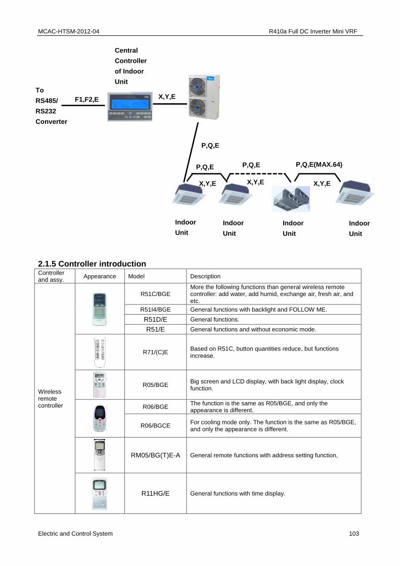
Besides, CCM03 can also connect indoor units via the port X Y E of indoor unit. However, one more
group of wire(X Y E between indoor units) is needed; it is more complex and not suggested. Anyway, the
diagram below shows the connection of signal wire in this case (Availabe for all models):
F1,F2,E To
RS485/
RS232
Converter
P,Q,E
X,Y,E
Central
Controller of
Indoor Unit
P,Q,E P,Q,E P,Q,E(MAX.64)
Indoor
Unit
Indoor
Unit Indoor
Unit
Indoor
Unit
MCAC-HTSM-2012-04 R410a Full DC Inverter Mini VRF
Electric and Control System 103
2.1.5 Controller introduction Controller and assy.
Appearance Model Description
Wireless remote controller
R51C/BGE More the following functions than general wireless remote controller: add water, add humid, exchange air, fresh air, and etc.
R51I4/BGE General functions with backlight and FOLLOW ME.
R51D/E General functions.
R51/E General functions and without economic mode.
R71/(C)E Based on R51C, button quantities reduce, but functions increase.
R05/BGE Big screen and LCD display, with back light display, clock function.
R06/BGE The function is the same as R05/BGE, and only the appearance is different.
R06/BGCE For cooling mode only. The function is the same as R05/BGE, and only the appearance is different.
RM05/BG(T)E-A General remote functions with address setting function,
R11HG/E General functions with time display.
F1,F2,E To
RS485/
RS232
Converter
P,Q,E
X,Y,E
Central
Controller
of Indoor
Unit
P,Q,E P,Q,E P,Q,E(MAX.64)
X,Y,E X,Y,E X,Y,E
Indoor
Unit Indoor
Unit
Indoor
Unit
Indoor
Unit

R410a Full DC Inverter Mini VRF MCAC-HTSM-2012-04
104 Electric and Control System
Wired controller
KJR-10B/DP(T)-E Connection needs that the indoor unit display panel contains a corresponding port.
KJR-10B/DPC(T)-E The function is generally the same as the KJR-10B/DP(T)-E, but excluding the heat mode.
KJR-12B/DP(T)-E This controller integrate FOLLOW ME function, others is the same with KJR-10B/DP(T)-E.
KJR-12B/DPBG(T)-E
Based on the KJR-12B/DP(T)-E and designed with backlight.
KJR-90A All basic function is the same as KJR-10B/DP(T)-E.
KJR-90A1-E To avoid mode confliction running mode is fixed to cool mode, other functions are the same as KJR-90A.
Central control monitor
MD-CCM01/E
1st generation central control monitor of indoor unit. Control Max 64 indoor units. It may set and check only one indoor unit, and also set and check all indoor units in common. PC control function may connect 2nd generation or 3rd generation network control system.
MD-CCM03/E(M) 2nd generation central control monitor of indoor unit. Add mode lock, big screen appearance, blue back light display, and mode memory function based on MD-CCM01/E.
MD-CCM09/E The weekly central controller of indoor unit. Control Max. 64 indoor units and possess week schedule function, but cannot connect network control system.
KJR-90B/M New general controller of indoor unit. It is only switch, which cannot change special mode, but it can simultaneously switch max. 16 indoor units.
Building gateway
MD-CCM07/E Building gateway connects to Lonworks® network for integrating to other BMS to realize air conditioner manage and control. It needn’t match Midea network system and PC.
MD-CCM08/E Building gateway connects to BAKNET network for integrating to other BMS to realize air conditioner manage and control. It needn’t match Midea network system and PC.
Network control software
MDV-WLJKXT/E(V3.1)(Firebird)
The 3rd
generation network control software with Firebird data. Add network fee charge function and connect the outdoor unit CCM based on the 2
nd generation network central control
system. It may connect to 16 indoor unit CCM and 1024 indoor units, and also connect to 16 outdoor unit CCM and 128 refrigeration systems.
Hotel card-inserter assy.
MD-NIM05/E Match hotel card system to control the air conditioner.
Infrared sensor
MD-NIM09/E Automatically turn off and turn on the indoor unit, saving energy.

MCAC-HTSM-2012-04 R410a Full DC Inverter Mini VRF
Electric and Control System 105
2.2 Wireless Remote Controller
Controller Appearance Model Description
Wireless remote controller
R51C/BGE The following functions are more than general wireless remote controller: add water, add humid, exchange air, fresh air, and etc.
R51D/E General functions.
R51/E General functions and without economic mode.
R51I4/BGE General functions with backlight and FOLLOW ME.
R71/(C)E Based on R51C, button quantities reduce, but functions increase.
R05/BGE Big screen and LCD display, with back light display, clock function.
R06/BGE The function is the same as R05/BGE, and only the appearance is different.
R06/BGCE For cooling mode only. The function is the same as R05/BGE, and only the appearance is different.
R11HG/E General functions with time display.
RM05/BG(T)E-A General remote functions with address setting function,

R410a Full DC Inverter Mini VRF MCAC-HTSM-2012-04
106 Electric and Control System
2.2.1 Wireless remote controller R51C/BGE, R51D/E,R51/E,R51I4/BGE
Apply to One-way/four way cassette/ Concealed duct/ Wall mounted type
2.2.1.1 Buttons and functions descriptions
① TEMP: Push the TEMP button to decrease the indoor temperature setting or to adjust the TIMER
in a counter-clockwise direction.
② MODE: Each time you push the button, a mode is selected as the following figure indicates:
Note: ―HEAT‖ is only for heat pump AC.
③ SWING: Push this switch button to change the louver angle.
④ RESET: Pushed, all current settings are cancelled and the control will return to the initial settings.
⑤ ECONOMIC RUNNING: Push this button to go into the Energy-Saving operation mode.
⑥ LOCK: Push this button to lock in all the current settings. To change the settings, push the button
once more.
⑦ CANCEL: Push this button to cancel the TIMER settings.
⑧ TIMER: Preset the time ON (start to operate) and the time OFF (turn off the operation).
⑨ ON/OFF: Push this button to start the unit operation. Push the button again to stop the unit operation.
⑩ FAN SPEED: This button is used for setting Fan Speed in the sequence that goes from AUTO, LOW,
MED to HIGH, then back to Auto.
TEMP: Push the button to increase the indoor temperature setting or to adjust the TIMER in a clockwise direction.
VENT: Push this button to set the ventilating mode. The ventilating mode will operate in the following sequence:
Note: ventilation function is available for the fresh air series.

MCAC-HTSM-2012-04 R410a Full DC Inverter Mini VRF
Electric and Control System 107
LCD display indications:
1--TRANSMISSION Indicator; 2--MODE Display; 3--HEAT PUMP ONLY-LOCK display; 4--TIMER Display; 5--FAN Display; 6--Digital Display Area.
2.2.2 Wireless remote controller R71/(C)E
Based on R51C, button quantities reduce, but functions increase.
1. Operating Mode: COOL HEAT DRY FAN only and AUTO.
2. Timer Setting Function in 24 hours.
3. Indoor Setting Temperature Range: 17℃~30℃.
4. LCD (Liquid Crystal Display) of functions.
Model R71/E,R71/CE
Rated Voltage 3.0V
Lowest Voltage 2.0V
Reaching Distance 8M(when using 3.0 voltage, it gets 11M)
Environment Temperature
Range
-5℃~60℃
2.2.2.1 Buttons and functions descriptions
①On/off Button: Push this button to start the unit operation. Push it again to stop the unit operation.
②Mode Button: Each time you press the button, a mode is selected in a sequence that goes from
AUTO COOL DRY HEAT and FAN. NOTE: HEAT only for Heat Pump
③ Button: Push the button to increase the indoor temperature setting to 30.

R410a Full DC Inverter Mini VRF MCAC-HTSM-2012-04
108 Electric and Control System
④ Button: Push the button to decrease the indoor temperature setting to 17.
⑤Fan Button: For selecting Fan Speed. Each time you press the button, a fan speed is selected in a
sequence that goes from AUTO LOW MED to HIGH, then back to auto. When you select the AUTO or
DRY mode, the fan speed will be automatically controlled and you cannot set the fan speed.
⑥Sleep Button: Press this button to go into the Energy-Saving operation mode, press the button again
to stop operation. When the operation mode is either DRY or FAN only, this function cannot be used.
⑦Swing Button: Press the SWING button to activate the swing feature. Push the button again to stop.
⑧Air direction Button: Press this button to change the swing angle of the louver. The swing angle of
the louver is 6° for each press. When the louver swing at a certain angle which would affect the cooling
and heating effect of the air conditioner, it would automatically change the swing direction. No symbol
will appear in the display area when press this button.
⑨Timer on Button: Press this button to initiate the auto-on time sequence. Each press will increase the
auto-timed setting in 30 minutes increments. When the setting time displays 10Hr, each press will
increase the auto-timed setting 60 minutes increments. To cancel the auto-timed program, continue
pressing the button until nothing displays.
⑩Timer off Button: Press this button to initiate the auto-off time sequence. Each press will increase the
auto-timed setting in 30 minutes increments. When the setting time displays 10Hr, each press will
increase the auto-timed setting 60 minutes increments. To cancel the auto-timed program, continue
pressing the button until nothing displays.
2.2.2.2 LCD display indications:
①TRANSMISSION Indicator: This indicator lights when controller transmits signals to indoor unit.
②MODE indicator: Displays the current operation modes. Including AUTO, COOL, DRY, HEAT or FAN.
Heat is only available for heat pump model.
③TEMPERATURE indicator: Displays the temperature settings (17 to 30).
④FAN SPEED indicator: Display the selected fan speed. Including AUTO and three fan speed levels
LOW, MED, HIGH. Display (flashing) when the operating mode is either AUTO or DRY.
⑤SLEEP indicator: When the Sleep button is pushed, this signal indicator lights. Nothing appears
when the operating mode is either DRY or FAN only.
⑥SWING indicator: This indicator lights up when the SWING button is pressed.
⑦TIMER indicator: The time set for timer operation is indicated. (0.5 ~ 24 hours)
2.2.3 Wireless remote controller R05/BGE, RM05/BG(T)E-A
Apply to Ceiling and floor type / four-way cassette type.
Model R05/BGE
Rated Voltage 3.0V(2 pieces of LR03 7# batteries)
Lowest Voltage 2.4V
Effective Distance 8M~11M
Operation Condition -5℃~60℃

MCAC-HTSM-2012-04 R410a Full DC Inverter Mini VRF
Electric and Control System 109
2.2.3.1 Buttons and functions descriptions
1. MODE: Each time you push the button, a mode is selected as the following figure indicates:
Note: ―HEAT‖ is only for heat pump AC. 2. FAN SPEED: This button is used for setting Fan Speed in the sequence that goes from AUTO, LOW, MED to HIGH, then back to Auto.
3. TEMP: Push the TEMP button to decrease the indoor temperature setting or to adjust the TIMER
in a counter-clockwise direction.
4. TEMP: Push the button to increase the indoor temperature setting or to adjust the TIMER in a
clockwise direction.
5. ON/OFF: Push this button to start the unit operation. Push the button again to stop the unit operation.
6. SWING: Push this switch button to change the louver angle.
7. CANCEL: Push this button to cancel the TIMER settings.
8. Air direction: Activate swing function of air deflector. Once pressed, air deflector will turn 6 degrees.
9. CLOCK: Use to set the time.
10. TIME ON: turn on the timer operation.
11. TIME OFF: turn off the timer operation. 12. RESET: Pushed, all current settings are cancelled and the control will return to the initial settings.
13. LOCK: Push this button to lock in all the current settings. To change the settings, push the button
once more.
14. OK: Used to confirm the time settings and modification.
15. C/H: Used this button to change the machine to Cooling mode or Cooling/Heating mode.
16. ECONOMIC RUNNING: Push this button to go into the Energy-Saving operation mode.
2.2.3.2 LCD display indications:

R410a Full DC Inverter Mini VRF MCAC-HTSM-2012-04
110 Electric and Control System
① Temp: Display the setting temperature.
② Transmitting display: This indicates that the remote controller is sending data.
③ ON/OFF: This indicates that the machine is on .
④ Running mode: This indicates the machine's running mode. Heating mode need the
corresponding type of unit.
⑤ Time: Display the current time. User could press the CLOCK button for 5s to make this flash,
then user could adjust the time by using the ▲and ▼ buttons. Once time is right, press the OK button to
confirm it.
⑥ Lock: When displayed, all the buttons are ineffective except the lock button.
⑦ Timer ON/OFF: This indicates the timer is working or not.
⑧ Economic operation: Indicates that whether the machine is working at the economic
operation.
⑨ Fan speed: Shows the indoor unit's fan speed. The longer it's displayed, the stronger the wind
blows.
Note: RM05/BG(T)E-A is able to set the indoor units’ addresses individually. Please refers the details
to the summary.
2.2.4 Wireless remote controller R06/BGE, R06/BGCE
The R06/BGE function is the same as R05/BGE, and only the appearance is different.
1. Operating Mode: AUTO, COOL, HEAT, DRY, and FAN.
2. Timer Setting Function in 24 hours.
3. Indoor Setting Temperature Range: 17℃~30℃.
4. LCD (Liquid Crystal Display) of all functions.
Model R06(A)/BG(C)E
Rated Voltage 3.0V(Alkaline dry batteries LR03×2)
Lowest Voltage of CPU Emitting Signal
2.0V
Transmission Distance 8m(when using 3.0 voltage, it gets 11m)
Environment -5℃ to 60℃

MCAC-HTSM-2012-04 R410a Full DC Inverter Mini VRF
Electric and Control System 111
2.2.4.1 Buttons and functions descriptions
ON/OFF Button: Push this button to start operation, push the button again to stop operation. MODE Button: Each time you push the button, a mode is selected in a sequence that goes from AUTO, COOL, DRY, HEAT and FAN. NOTE: COOL only model has no HEAT feature. SWING Button: Push the button, the louver would swing up and down automatically. Push again to stop. DIRECTION Button: Press this button to change the swing angle of the louver. The swing angle of the
louver is 6° for each press. When the louver swing at a certain angle which would affect the cooling
and heating effect of the air conditioner, it would automatically change the swing direction. No symbol will appear in the display area when press this button.
TEMP/TIME Button: Push the button to increase the indoor temperature setting or to adjust the TIMER in a clockwise direction. Push the button to decrease the indoor temperature setting or to adjust the TIMER in a counter-clockwise direction. TURBO Button: Push this button on COOL mode, the air conditioner goes into powerful cooling operation. Push again to cancel the TURBO function. SLEEP Button: Press this button to go into the Energy-Saving operation mode. Press it again to cancel. This function is only can be used on COOL, HEAT and AUTO mode and maintain the most comfortable temperature for you. NOTE: While the unit is running under SLEEP operation mode, it would be canceled if you press the other button. RESET Button: When you press the recessed RESET button, all current settings are cancelled and the control will return to the initial settings. FAN Button: Used to select the Fan Speed in four steps AUTO, LOW, MED or HIGH. Each time the button is pressed, the fan speed mode is shifted. TIMER Button: This button is used to preset the time ON (start to operate) and the time OFF (turn off the operation). CANCEL Button: Push this button to cancel the TIMER ON/OFF settings. CLOCK Button: Use to set the time. LED Button: Press this button to clear the digit display in the air conditioner, press it again to activate it. LOCK Button: When you press the LOCK button, all current settings are locked in and the remote controller does not accept any operation except that of the LOCK. Press again to cancel the LOCK mode. O2 Button (optional): Push this button to activate the oxygen generating mechanism, and the oxygen density of indoor varies. Push again to stop the function.
R410a Full DC Inverter Mini VRF MCAC-HTSM-2012-04
112 Electric and Control System
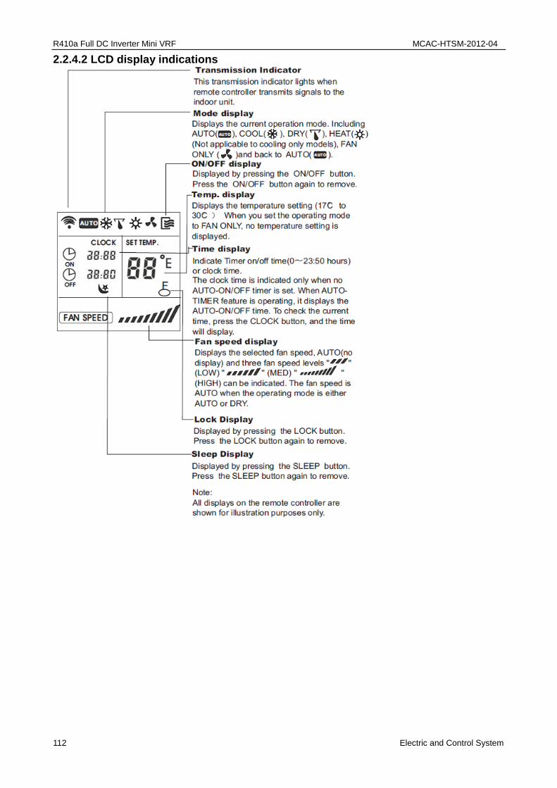
2.2.4.2 LCD display indications

MCAC-HTSM-2012-04 R410a Full DC Inverter Mini VRF
Electric and Control System 113
2.2.5 Wireless remote controller R11HG/E
2.2.5.1 Buttons and functions Descriptions Mode select button: Each time you push the button, a mode is selected in a sequence that goes from AUTO, COOL, DRY, HEAT (cooling only type without), FAN ONLY and back to AUTO. Fan speed button: This button is used for selecting fan speed. Each time you push the button, a fan speed is selected in a sequence that goes from AUTO, LOW, MED, HIGH, and back to AUTO. ON/OFF button: Push the button to start operation, push the button again to stop operation. Temperature button: To adjust the temperature, ranging from 17 to 30 degree. Wind directory button: Push this button to change the swing angle of louver. (This is not available for the unit without this function.) Auto louver button: Push this button to swing louver. Push the button again to stop. Clock button: Push this button to set the time. Reserve button: This key is used for confirming the timer settings. Cancel button: Pressing this key will lead to ON Timer and OFF Timer canceling. Economy running button: Press this key to start the indoor units’ economic mode. ON/OFF timer: Press ON timer to start the setting of ON timer. Press OFF timer to start the setting of OFF timer. Timer adjust button: Adjust the time when setting current time or setting timer. Lock button: This button is used to prevent other keys from functioning. Press this key again to cancel this. Reset button: When you push the RESET button, all current settings are cancelled and get into the condition of beginning. In the clock, the colon in "0:00" will flash, the mode displays "AUTO", fan speed displays "AUTO" the temperature displays "24".

R410a Full DC Inverter Mini VRF MCAC-HTSM-2012-04
114 Electric and Control System
2.2.5.2 LCD display indications

MCAC-HTSM-2012-04 R410a Full DC Inverter Mini VRF
Electric and Control System 115
Summary: Comparison of remote controllers
Function
R05
/BG
E
RM05/
BG(T)
E-A
R06/B
GCE
R06/B
GE
R11H
G/E
R51C/
BGE
R51D/
E R51/E
R51I4/
BGE
R71A/
E
On/Off ● ● ● ● ● ● ● ● ● ●
Cooling mode
● ● ● ● ● ● ● ● ● ●
Heating mode
● ● ─ ● ● ● ● ● ● ●
Fan mode ● ● ● ● ● ● ● ● ● ●
Dehumidifying mode
● ● ● ● ● ● ● ● ● ●
Auto mode
● ● ● ● ● ● ● ● ● ●
Swing function ● ● ● ● ● ● ● ● ● ●
Economic mode
● ● ─ ─ ● ● ●
─ ● ●
Remote controller lock
● ● ● ● ● ● ● ● ● ●
Fan speed control
● ● ● ● ● ● ● ● ● ●
Daily time setting
● ● ─ ─ ●
─ ─ ─ ─ ─
Background light ● ● ● ●
─ ● ─ ─ ●
─
Current time
● ● ─ ─ ●
─ ─ ─ ─ ─
FOLLOW ME
─ ─ ─ ─ ─ ─ ─ ─ ● ─
Address setting
─ ● ─ ─ ─ ─ ─ ─ ─ ─
How to set address through Wireless Remote Controller
1) Press the LOCK button for more than 5 seconds, then the controller get into address setting mode.
2) Then press the ON/OFF button to start transmitting signal in the address setting mode. When working
in address setting mode, press ON/OFF will not turn the controller off.
3) In the address setting mode, there are 2 main functions:
Querying mode: Please point the remote controller to the indoor unit, then press MODE button, the
corresponding indoor unit will display its address.
Setting mode: Use the UP and DOWN buttons to choose an address you want. Then point the remote
controller to the indoor unit and then press the FAN button to set the indoor unit’s address. The
corresponding indoor unit will display the new address and record it. After about 4 seconds, this

R410a Full DC Inverter Mini VRF MCAC-HTSM-2012-04
116 Electric and Control System
displaying will fade out and the indoor unit turn to normal display mode.
4) After setting all the addresses, users can press the LOCK button for 5 seconds to quit the address
setting mode.
2.3 Wired Controller
Controller Appearance Model Description
Wired controller
KJR-10B/DP(T)-E General control function. Connected to the indoor unit display panel's corresponding port.
KJR-10B/DPC(T)-E The function is generally the same as the KJR-10B/DP(T)-E, but excluding the heat mode.
KJR-10B/DP(T)-E (Korean)
A Korean Edition bases on the KJR-10B/DP(T)-E.
KJR-12B/DP(T)-E This controller integrate FOLLOW ME function, others is the same with KJR-10B/DP(T)-E.
KJR-12B/DPBG(T)-E
Bases on the KJR-12B/DP(T)-E and is with backlight, vertical and level swing function.
Dun-KJR-12B/DP(T)-E
FOLLOW ME and configured with a 20M wire. There’s no brand and backlight on it.
KJR-90A All basic function is the same as KJR-10B/DP(T)-E.
KJR-90A1-E To avoid mode confliction running mode is fixed to cool mode, other functions are the same as KJR-90A.
Safety precautions:
Please read this safety precaution carefully, before installation. Do observe the following safety
precautions, for they are very important.
Confirm there is no abnormal phenomenon during test operation after installation completed, then hand
the manual to the user.
Installation must be conducted by professionals;
Improper installation may cause electric shock or fire.
A random disassembly may cause abnormal operation or heating, which may result in fire.
Don't install it in a place where combustible gas easily leaks. Once combustible gas leaks and remains
around Controller, fire may be caused.
Wire must be suitable for the current of Controller. Otherwise electricity leakage or heating may be
caused, which may result in fire.
Wire must be suitable for controller, never bring outside force to bear on the terminal. Otherwise wire
break or heating may be caused, which may result in fire.
Installation location:
Do not install it in a place with oil, steam or sulphur gas, or else deform or malfunction may occur.
Wire controller installation notice:
1. This installation manual contains information about the procedure of installing Wire Controller.
Please refer to Indoor Unit Installation Manual for connecting between Wire Controller and Indoor Unit.
2. Circuit of Wire Controller is low voltage circuit. Never connect it with a standard 220V/380V circuit or

MCAC-HTSM-2012-04 R410a Full DC Inverter Mini VRF
Electric and Control System 117
put it into a same Wiring Tube with the circuit.
3. The shield cable must be connected stable to the ground, or transmission may fail.
4. Do not attempt to extend the shield cable by cutting, if it is necessary, use Terminal Connection Block
to connect.
5. After finishing connection, do not use Megger to have the insulation check to the signal wire.
Note: When the air conditioner needs the constant frequency wire Controller, be sure adding a Wire Joint
with 5 terminal named A, B, C, D, E in indoor unit, and fixing a infrared emitter whose anode and cathode
connecting with A and B near the receiver in the Indoor Unit Switch Board, then connecting the terminal
+5V, GND, Run in the Switch Board to C, D, E respectively.
2.3.1 Wired controller KJR-10B
2.3.1.1 Appearance
Apply to One-way/four way cassette/ Concealed duct/ Ceiling and floor/ Wall mounted type
Button ○13 : For some machines with auxiliary electric heater, this button may help with change the
machines in to cooling mode only. Factory default setting is cooling and heating mode both exist. Some
types do not have this button.

R410a Full DC Inverter Mini VRF MCAC-HTSM-2012-04
118 Electric and Control System
2.3.1.2 Installation
Dimensions:120*120*15mm

MCAC-HTSM-2012-04 R410a Full DC Inverter Mini VRF
Electric and Control System 119
Preparation before Installation:
Make sure the following pasts has been prepared.
NO. Name QTY. Remarks
1 Wired Controller 1 With Cover
2 Wood Mounting Screw 3 M4×20(For mounting on the wall)
3 Mounting Screw 3 M4×25(For Mounting on the electrical switch box)
4 Installation Manual 1 -
5 Owner's Manual 1 -
Prepare for the following at installation site.
NO. Name QTY. Remarks
Install into
the wall
Install on
the wall
1 5-core Shield Cable 1 1 0.05mm2×5 Cable no more than 15M
2 Switch Box 1 - -
3 Wiring Tube(Insulating Sleeve and
Tightening Screw)
1 - -
Note: Do not turn screws too tightly, or else the cover would be sunk or the Liquid Crystal may be broken.
2.3.2 Wired controller KJR-12B
2.3.2.1 Appearance Apply to the customized indoor unit. Add ambient temperature displaying function based on KJR-10B/DP(T)-E.

R410a Full DC Inverter Mini VRF MCAC-HTSM-2012-04
120 Electric and Control System
Button ○4 : This button is not designed on all the types. If exists, it stand for economic running mode.
Button ○6 : There are 2 type of this button.
AUXIL HEATER: Auxiliary electricity heater. TURBO: In cooling mode, this button stands for powerful cooling mode, available to some mode
designed with this function. In heating mode, this button will cause electric auxiliary ineffective.
Button ○12 : Pattern means the vertical swing function and "SWING" means the normal swing function.
Button ○13 : Pattern means the horizontal swing function and "ECO" means the economic function.

MCAC-HTSM-2012-04 R410a Full DC Inverter Mini VRF
Electric and Control System 121
2.3.1.2 Installation
Dimension:
120*120*15mm
Installation of wire controller:

R410a Full DC Inverter Mini VRF MCAC-HTSM-2012-04
122 Electric and Control System
Preparation before Installation:
Make sure the following pasts has been prepared.
NO. Name QTY. Remarks
1 Wired Controller 1 With Cover
2 Wood Mounting Screw 3 M4×20(For mounting on the wall)
3 Mounting Screw 3 M4×25(For Mounting on the electrical switch box)
4 Installation Manual 1 -
5 Owner's Manual 1 -
Prepare for the following at installation site.
NO. Name QTY. Remarks
Install into
the wall
Install on
the wall
1 5-core Shield Cable 1 1 0.05mm2×5 Cable no more than 15M
2 Switch Box 1 - -
3 Wiring Tube(Insulating Sleeve and
Tightening Screw)
1 - -
Note:
Never turn screws too tightly, or else the cover would be sunk or the Liquid Crystal breaks.
Installation of wired controller KJR-12B/DP(T)-E is the same to KJR-10B/DP(T)-E.
2.3.3 Wired controller KJR-90A
2.3.3.1 Appearance
Button description:
2.3.4.2 Installation
Dimension: 90*86*13mm

MCAC-HTSM-2012-04 R410a Full DC Inverter Mini VRF
Electric and Control System 123
Installation of wire controller:
Preparation before Installation:
Make sure the following pasts has been prepared.
NO. Name QTY. REMARK
1 Wired controller 1 —
2 Cruciform slot screw M4×25 2 The accessory is need when install the
wire controller to the electric cabinet. 3 Plastic bolt 2
4 Installation and owner's manual 1 —
5 Connective wires to the signal receive
panel
1 Shielded 5-core cable.
Prepare for the following at installation site.
NO. NAME QTY. REMARK
1 Electric cabinet 1 Universal electric cabinet's specification.
Pre-embed it into wall.
2 Shielded 5-core cable 1 Pre-embed RVVP-0.5mm2×5
3 Wire configured tube(insulate sheath) 1 Pre-embed into the wall and the length
should be less than 15m
4 Cruciform screwdriver 1 To install cruciform slot screw
5 Slotted head screw 1 To split the bottom from the wire controller

R410a Full DC Inverter Mini VRF MCAC-HTSM-2012-04
124 Electric and Control System
Summary
Comparison of wired controllers
Appearance
Model KJR-10B/
DP(T)-E
KJR-10B/
DPC(T)-
E
KJR-10B/
DP(T)-E
(Korean)
KJR-12B/
DP(T)-E
KJR-12B/
DPBG(T)
-E
Dun-KJR
-12B/DP
(T)-E
KJR-90A KJR-90A
1-E
On/off ● ● ● ● ● ● ● ●
Auto ● ● ● ● ● ● ● -
Cooling ● ● ● ● ● ● ● ●
Dehumidify ● ● ● ● ● ● ● -
Fan ● ● ● ● ● ● ● ●
Heating ● - ● ● ● ● ● -
On/off Timer ● ● ● ● ● ● ● ●
Temp. Setting ● ● ● ● ● ● ● ●
Horizon Swing ● ● ● ● ● ● ● ●
Vertical Swing - - - - ● - - -
Economical
mode ● ● ● ● ● ● - -
FOLLOW ME - - - ● ● ● - -
Backlight - - - - ● - - -
Powerful cooling - - - - ● - - -
Lock mode ● ● ● ● ● ● - -
Cooling/Cooling
& Heating
Selection
● - ● - - - - -
Electric Auxiliary
Heating ON - - - - - ● - -

MCAC-HTSM-2012-04 R410a Full DC Inverter Mini VRF
Electric and Control System 125
2.4 Central Control Monitor
2.4.1 Central control monitor MD-CCM03/E(M)
Central control monitor MD-CCM03/E(M) is a remote wired controller that is used for controlling up to 64
indoor unit. Moreover, we could create our AC network with this device, including the PC central
monitoring system and the BMS(Building Management System).
Memory function: It can record the running parameters (mode/fan speed/temp.) when using the
controller to turn on the indoor units, all the unit will work as the last setting.
Automatically record all setting info when lose power
RS485 communication protocol
Clear & bright LCD display screen,
Background light, more parameters
display
Emergency ON/OFF control with
simple dry contact input
2.4.1.1 System configure
With MD-CCM03/E(M), we could both
centrally control the indoor units and
bridge up to 64 indoor units to the PC
monitoring software or BMS. In fact, on
the purpose of connecting the indoor units
to the PC or the gateway, which makes
the indoors units visible and can be controlled, MD-CCM03/E (M) is necessary.
1. All the indoor units and outdoor units are V4+ series , the topology of the network is as follows:
Controller Appearance
Model Description
Centralized Controller
MD-CCM03/E(M)
No.2 generation central control monitor of indoor unit. Add mode lock, big screen appearance, blue back light display, and mode memory function based on MD-CCM01/E.
MD-CCM09/E The weekly schedule central controller of indoor unit. Control Max. 64 indoor units and possess week schedule function, but cannot connect network control system.
KJR-90B/M New general controller of indoor unit. It is only switch, which cannot change special mode, but it can simultaneously switch max. 16 indoor units.
KJRF-180A/MBT-E
Be able to control up 16 indoor units and a water heater, including one fresh air unit.
KJR-31B/E Be able to lock up to 64 indoor units’ running mode to avoid modes conflict.

R410a Full DC Inverter Mini VRF MCAC-HTSM-2012-04
126 Electric and Control System
2.The indoor units contains any V4 series, the network topology is as follows:
For the 2nd
type of network topology, either of the connection below is available:
P,Q,E
232/485
MAX:
1024 indoor units
512 outdoor units
MAX: 16 CCM02
CCM03
F1,F2,E
MAX: 8 Systems
232/485 converter CCM03
MAX: 16 CCM03 MAX:
1024 indoor units
512 outdoor units
P,Q,E
X,Y,E
MAX. 8 systems
F1,F2,E

MCAC-HTSM-2012-04 R410a Full DC Inverter Mini VRF
Electric and Control System 127
To establish a steady network the following should be noted
The signal wire should be 3-core shielded wire and the wire should be provided by licensed
electricians.
To make signal transmission steady and to protect the facilities, the signal transmission wires should
not be near to the power line. An interval of 300mm-500mm should exist between these two kinds of
wires.
The signal wire of each network should be less than 1,200m.
The unit and the centralized controller should be connected hand-in-hand, which means that all the
units’ same port should be connected to a 3-core wire and the signal wire should be linear in
topology. Or else, the facilities could not work normally.
2.4.1.2 Description Names and Functions
Keywords and general function description
1 Power on or reset
When the centralized controller is powered on or reset, all display segments of the LCD are luminous for
2 seconds and then goes off. 1 second later, the system enters the normal display status. The
centralized controller is in the main page display status and displays the first page, and searches the
in-service air conditioners in the network. Once the search is finished, the centralized controller enters
the mode setting page, and sets the first in-service air conditioner by default.
2 Network area address of centralized controller
The local computer or gateway can be connected with 16 centralized controllers for communication.
Each centralized controller serves as an area of the air conditioner network. The centralized controllers
are differentiated by bit selection address. The configurable range is 0~15.
3 State indications
If any local keypad operation is setting the operation status of the air conditioner, the indicator is on when
the signals are sent. Upon completion of the setting process, the indicator goes off. If an in-service air
conditioner in the network is faulty, or the centralized controller network itself is faulty, the indicator will

R410a Full DC Inverter Mini VRF MCAC-HTSM-2012-04
128 Electric and Control System
blink at 2Hz.
If one or more in-service air conditioners in the network are running, including under setting of timing
start/shutdown, the indicator will be luminous. Otherwise, the indicator is off.
4 Locking of centralized controller
After receiving the centralized controller locking command sent from the computer, the centralized
controller disables the startup/shutdown and setting of the air conditioner, and sends commands to lock
remote controllers of all air conditioners in the network of the centralized controller. After receiving the
unlocking command, the centralized controller enables the startup/shutdown operation, and sends
commands to unlock the remote controller of all air conditioners.
The locking status of the remote controller can be locked or unlocked by the computer or centralized
controller separately. The locking status of the centralized controller is memorized after power failure of
the centralized controller, and will not vanish after the power supply is restored, unless the command of
unlocking is received.
5 Mode locking function
After the mode locking command is received, the command is forwarded to the air conditioner, and the
centralized controller displays the mode locking flag. After the command of unlocking is received, the
non-conflict mode can be selected freely. The centralized controller can also lock modes of all indoor
units.
6 Emergent shutdown and compulsory startup
When the emergent shutdown switch of the centralized controller is shorted, all air conditioners in the
network of the centralized controller will shut down compulsorily. The centralized controller and computer
and all functional modules are disabled from startup and shutdown until the foregoing switch is open.
When the compulsory startup switch of the centralized controller is shorted, all air conditioners in the
network of the centralized controller will start up compulsorily. In default conditions, they will run in the
cooling mode. The startup and shut down operations of the centralized controller and the computer and
all functional modules will be disabled (only the command of startup is sent to the air conditioner, without
affecting operation of the remote controller after startup) until the foregoing switch is opened.
If the foregoing two switches are shorted in the same time, the emergent shutdown switch shall have
preference.
Liquid Crystal Display:

MCAC-HTSM-2012-04 R410a Full DC Inverter Mini VRF
Electric and Control System 129

R410a Full DC Inverter Mini VRF MCAC-HTSM-2012-04
130 Electric and Control System
Note:
Each grid composes two blocks, whose sizes are different and indicates different status. Indications are
as follows:
status
Object
Constantly on Slow blink Fast blink Disappeared
Big block Unit is in service Selected Out of service
Small block Power is on Unit malfunction Power is off
Buttons and Functions
1) Query key
Any time when you press the key, the selected operation mode is to query the operation status of the air
conditioner. By default, the first in-service air conditioner will be queried. Through the Increase and
Decrease keys, you can change the parameter page to be queried; through the Up, Down, Left and
Right keys, you can change to query status of other in-service air conditioners.
2) Set key
In other display mode, press the key to enter the setting mode. By default, it is single setting, and the first
in-service air conditioner is displayed. In setting operation mode, press the key again, and the operation
will be performed for all air conditioners in the network. Press the key repeatedly to shift between single
setting and global setting.
→ Single → Global →

MCAC-HTSM-2012-04 R410a Full DC Inverter Mini VRF
Electric and Control System 131
3) Mode key
In setting operation mode, press this key to set the operation
→cooling → heating → supply air only → stop →
In other display mode, press the key to enter the setting mode. By default, it is single-machine setting,
and the first in-service air conditioner is displayed.
4) Fan key
In setting operation mode, press this key to set the fan of the indoor unit of the air conditioner to run in
the automatic, high, medium or low level of air.
→ auto → low → medium → high →
5) Time on key
In setting operation mode, press this key to set the timing startup of air conditioner; press the key again
to exit the timing setting, and restore the normal temperature regulation operation mode.
→ time on → set temperature regulation →
6) Time off key
In setting operation mode, press this key to set the timing shutdown of air conditioner; press the key
again to exit the timing setting, and restore the normal temperature regulation operation mode.
→ time on → set temperature regulation →
7) Swing
In setting operation mode, press this key to enable or disable the swing function. If all currently selected
air conditioners have no swing function, no effect will result after pressing the key.
8) Leftward key
In the query mode, every time when you press the key, the operation status data of the previous air
conditioner will be displayed. If it is currently on the first machine, press the key again, and the data of
the last machine will be displayed. If you hold down this key, the address will decrease one by one.
In the setting mode, every time when you press the key, if it is in single operation mode, the air
conditioner of the previous in-service address number will be selected. If it is in the global operation
mode, no effect will result after the key is pressed.
In the main page, press the key to enter the query mode. By default, it is the first air conditioner
in-service.
9) Rightward key
In the query mode, every time when you press the key, the operation status data of the last air
conditioner will be displayed. If it is currently on the last machine, press the key, and the data of the first
machine will be displayed. If you hold down this key, the address will increase one by one.
In the setting mode, every time when you press the key, if it is in the single operation mode, the air
conditioner of the next in-service address number will be selected. If it is in the global operation mode,
no effect will result after the key is pressed.
In the main page, press the key to enter the query mode. By default, it is the first in-service air
conditioner.

R410a Full DC Inverter Mini VRF MCAC-HTSM-2012-04
132 Electric and Control System
10) Downward key
In the query mode, every time when you press the key, the operation status data of the air conditioner
corresponding to the next row of the matrix will be displayed. If it is currently in the last row, press the key,
and the data of the air conditioner corresponding to the first row will be displayed. If you hold down this
key, the row will increase one by one.
In the setting mode, every time when you press the key, if it is in the single operation mode, the air
conditioner corresponding to the last row will be selected. If it is in the global operation mode, no effect
will result after the key is pressed.
In the main page, press the key to enter the query mode. By default, it is the first in-service air
conditioner.
11) Upward key
In the query mode, every time when you press the key, the operation status data of the air conditioner
corresponding to the previous row of the matrix will be displayed. If it is currently in the first row, press
the key, and the data of the air conditioner corresponding to the last row will be displayed. If you hold
down this key, the row will decrease one by one. In the setting mode, every time when you press the key,
if it is in the single operation mode, the air conditioner corresponding to the previous row will be selected.
If it is in the global operation mode, no effect will result after the key is pressed.
In the main page, press the key to enter the query mode. By default, it is the first in-service air
conditioner.
12) Add key
In the main page or the query mode, every time when you press the key, the data of the last page will be
displayed. If it is now in the last page, press the key again, and the first page will be displayed.
In the setting mode, every time when you press the key, if it is in the temperature regulation mode, the
set temperature will decrease by 1 °C until the highest allowed set temperature; if it is in the timing
startup/shutdown time setting mode, select the upper-level set time, if no time is set, 0.0 will be displayed,
if you hold down the key, the upper-level data will be selected consecutively.
The specific change mode is as follows:
0.0→0.5→1.0→1.5→2.0→2.5→3.0→3.5→4.0→4.5→5.0→5.5→6.0→6.5→7.0→7.5→ 8.0→8.5→9.0
→9.5→10→11→12→13→14→15→16→17→18→19→20→21→22→23→24
13) Reduce key
In the main page or the query mode, every time when you press this key, the data of the current page will
be displayed. If it is now in the first page, press the key again, and the last page will be displayed.
In the setting mode, every time when you press the key, if it is in the temperature regulation mode, the
set temperature will decrease by 1 degree until the lowest allowed set temperature; if it is in the timing
startup/shutdown time setting mode, select the upper-level set time, if no time is set, 0.0 will be displayed,
if you hold down the key, the upper-level data will be selected consecutively.
The specific change mode is as follows:
0.0← .5←1.0←1.5←2.0←2.5←3.0←3.5←4.0←4.5←5.0←5.5←6.0←6.5←7.0←7.5←8.0←8.5 ←9.0←
9.5←10←11←12←13←14←15←16←17←18←19←20←21←22←23←24
14) ON/OFF key
Any time when you press the key, the centralized startup/shutdown operation is performed for all current
in-service air conditioners in the centralized controller network. If all in-service air conditioners in the

MCAC-HTSM-2012-04 R410a Full DC Inverter Mini VRF
Electric and Control System 133
network are in the power-off status, press the key to perform the startup operation.
If it is in the mode setting page currently, and the parameters such as startup mode, temperature and air
speed are selected, the air conditioner will be started according to the selected parameters.
If no mode is selected currently, and the air conditioner is powered off or it is in other display page
currently, and the default startup mode is: Cooling, strong air, set temperature 24°C, swing function
enabled. The default startup mode is locked according to the system mode or judged according to other
constraint conditions. If any conflict exists, the next conflict-free mode will apply automatically. If conflict
exists for all modes, startup will be impossible. If one or more in-service air conditioners in the network
(including in the timing process of timing startup/shutdown), pressing this key will shut down all air
conditioners. When performing the shutdown operation, the shutdown command is issued to the air
conditioners in the startup status only, and is not issued to those in the shutdown status.
15) Lock key
In the mode setting mode, press the Lock key, and the remote controller of the currently selected air
conditioner will be locked/unlocked. The operation mode is: If you select single-machine setting, the
operation is performed for the air conditioner of the current address only. If the remote controller of the
air conditioner is locked currently, issue the lock command; otherwise, send the lock command. If you
does not select the single-machine mode, and the remote controller of one or more currently selected air
conditioners is locked, issue the unlock command; if the remote controllers of all currently selected air
conditioners are in the non-locked status, issue the remote controller lock command. When the remote
controller of the air conditioner is locked, the air conditioner does not receive remote control signals from
the remote controller or wire controller until the remote controller is unlocked. Press the Query key and
then press the Lock key, and the keys of the centralized controller will be locked or unlocked. If the keys
are currently locked, press the foregoing keys concurrently again, and the keys will be unlocked; if the
keys are currently unlocked, press the foregoing keys concurrently, and the keys will be locked. If the
keys are locked, pressing of any key other than the Unlock key will be ineffective.
In the unified setting page, press the Up key and the Lock key concurrently to lock all air conditioner
mode in the network. The mode locking is cancelled when the key is pressed again.
Note:
When you lock or cancel locking, the corresponding icon indication appears or disappears only after all
the air conditioners in-service are set completely, as a result, it take a while to finish the mission. When
the air conditioners in-service is many, wait patiently.
16) Confirmation key
In the setting mode, press the key to send the currently selected mode status and the auxiliary function
status to the selected air conditioner, and display the mode setting operation results.
After you select the operation mode and auxiliary function status information of the air conditioner, if you
do not press the confirmation key, the selected information will not be sent to the air conditioner, and will
not affect the current operation of the air conditioner.
The operations of remote controller locking and unlocking do not need pressing the confirmation key.
The command information is sent directly after the locking key is pressed.
17) Reset key
Anytime when the reset key is pressed, the centralized controller will reset. The result is the same as the
result of restoring power-on after power failure.

R410a Full DC Inverter Mini VRF MCAC-HTSM-2012-04
134 Electric and Control System
2.4.1.3 Installation
Note: To differentiate each centralized controller, the controllers in the same RS-485 net should be with different address with each other.

MCAC-HTSM-2012-04 R410a Full DC Inverter Mini VRF
Electric and Control System 135

R410a Full DC Inverter Mini VRF MCAC-HTSM-2012-04
136 Electric and Control System
Before starting the network, please confirm that every CCM03’s address is different with each other. 2.4.1.4 Query and Error code The CCM03 centralized controller offers the function of query of indoor units’ running state and displays the error code when some of the indoor units fail down.
1. Press the query button to activate the query function. Firstly the display panel will display the 1st units’ state. 2. Use the UP, DOWN, LEFT, RIGHT buttons to select the unit we want to query. The indication of error codes are as the 2 tables below:

MCAC-HTSM-2012-04 R410a Full DC Inverter Mini VRF
Electric and Control System 137
Fault code Content
EF Other faults
EE Water level detection faults
ED Outdoor unit fault
EC Cleaning fault
EB Inverter module protection
EA Current of compressor is too large (4 Times)
E9 Fault of communication between main board and display board
E8 Wind blowing speed is out of control
E7 EEPROM error
E6 Detection of current direction alternating is abnormal
E5 T3 or T4 temp. senor of discharge of compressor fails down
E4 T2B sensor fails to work normally
E3 T2A sensor fails to work normally
E2 T1 sensor fails to work normally
E1 Communication fault
E0 Phase sequence disorder or loss of power phase
07#
06#
05#
04#
03# Communication mistake between centralized controller and PC(gateway)
02# Communication mistake between centralized controller and functional module
01# Communication mistake between centralized controller and network interface module
00# Communication mistake between network interface module and main control board
Protection code Content
PF Other protection
PE Reserved
PD Reserved
PC Reserved
PB Reserved
PA Reserved
P9 Reserved
P8 Compressor’s current is too large
P7 Voltage of power supply is too high or too low
P6 Pressure of discharge is too low
P5 Pressure of discharge is too high
P4 Temp. of discharge pipe is abnormal
P3 Temp. of compressor is abnormal
P2 Condenser high-temperature protection
P1 Anti-cool air or defrost protection
P0 Evaporator temperature protection
2.4.2 Weekly schedule timer central controller MD-CCM09/E
MD-CCM09/E is designed base on the CCM03, max. 64 indoor units control, weekly schedule timer
function. With the function above, CCM09/E can’t be connected to the network control system. And
actually it does not have the port F1, F2, E, which are needed if connects to the computer.

R410a Full DC Inverter Mini VRF MCAC-HTSM-2012-04
138 Electric and Control System
7 -days Weekly schedule setting (Maximum 128
weekly & daily schedules)
Max. 64 indoor units group control or individual
setting
Clear and bright screen with LCD backlight
Temperature setting
Wireless remote control restriction
Sleep and Silent mode
Mode lock
Permanent schedule setting storage
2.4.2.1 System configure MD-CCM09/E is only centralized controller for indoor unit, but with this device we could set the indoor unit’s functions compactly and conveniently. 1. All the indoor units and outdoor units are V4+ series, the topology of the network can be as follows. Moreover the 2
nd way of connecting is also adaptable in this condition.
CCM09
MAX: 8 Systems
P,Q,E
P,Q,E

MCAC-HTSM-2012-04 R410a Full DC Inverter Mini VRF
Electric and Control System 139
2. The indoor units contains any V4 series, the network technology is as follows. MD-CCM09/E controller needs connecting it with other indoor units in a hand-in-hand way, which is the same connecting way with MD-CCM03. For the 2
nd type of topology, either of the connecting ways below
is available.
Expansive Function: MD-CCM09/E is also can be connected to the Network module MD-NIM01, which can assign a network address the indoor unit with this function.
CCM09
P,Q,E
X,Y,E
MAX. 8 systems
P,Q,E

R410a Full DC Inverter Mini VRF MCAC-HTSM-2012-04
140 Electric and Control System
To establish a steady network the following should be noted
Directly connect 20V~50/60Hz power supply to ends L and N of the socket on the back of the central controller.
The signal cable and power cable of the central controller cannot be contained in the same cable tube. The distance between the signal cable tube and power cable tube shall be between 300mm -500mm at least.
The total signal cable length of the central controller shall not exceed 1,200m. Make sure there is no joint in the middle of the shielded cable. If such a joint exists, use a socket to
connect it.

MCAC-HTSM-2012-04 R410a Full DC Inverter Mini VRF
Electric and Control System 141
2.4.2.2 Description Names and Functions

R410a Full DC Inverter Mini VRF MCAC-HTSM-2012-04
142 Electric and Control System
Icon Meaning Icon Meaning
Auto mode
Fan only mode
Cooling mode
Dry mode
Heating mode
Fan speed
Electric auxiliary heating
Heating mode only
Cooling mode only
Wireless controller lock
Lock keyboard
Set mode
Query mode
Operating result
Weekly timer off
All units are selected
Online status
Protection code follows
Error code follows
Set temperature
Corresponding period
Room temperature
Temp. of the middle of evaporator
Temp. of the outlet of the condenser
Temp. Of outdoor pipe
Monday
Tuesday
Wednesday
Thursday
Friday
Saturday
Sunday

MCAC-HTSM-2012-04 R410a Full DC Inverter Mini VRF
Electric and Control System 143
Display panel indications
1) The main interface of the weekly-timer central controller (user interface)
Under the other pages, press ‖CANCEL‖ to return to the main interface.
Under the other pages, automatically return to the main interface when no operation for a period of time.
The main interface displays the on-line condition of the indoor unit.
2) Setting interface of single weekly-timer central controller
Under the main interface, press to select to the single setting interface
Automatically return to the main interface when no operation for a period of time.
Set the running status of single air conditioner under this page.

R410a Full DC Inverter Mini VRF MCAC-HTSM-2012-04
144 Electric and Control System
3) Setting interface of weekly timer parameters of single weekly-timer central controller
Under the main interface, press to display the parameter setting interface of single weekly timer
Automatically return to the main interface if no operation is performed for a period of time.
Under this page, set the weekly timer parameters of single air conditioner, including startup time,
shutdown time, the running mode of this period, temperature and wind speed.
One air conditioner can be at most set with four periods in one day from Monday to Sunday, seven days
in total.
4) Unified setting interface of the weekly-timer central controller
Under the main interface, press ―SET‖ to display the unified setting interface.
Automatically return to the main interface if no operation is performed for a period of time.
Set the running mode of all air conditioners under this page, including mode, temperature and Fan
speed.

MCAC-HTSM-2012-04 R410a Full DC Inverter Mini VRF
Electric and Control System 145
Keyboard panel and button functions
1) On/Off key Press the ON/OFF button. All air conditioners will be shut down if they are running, on the contrary, they will be started up. If you press the button for less than 5 seconds, the startup mode is the last running mode of the air conditioner. If you press the button for more than 5 seconds, the startup mode is cooling, fan runs at high Speed, and the set temp. is 24 degrees. 2) SET key Press the SET button, and then select set single or set all. Set single indicates to set the parameter (such as mode/ temperature/Fan speed/ weekly timer) of an single selected air conditioner. Set all indicates to set the parameter of all air conditioners controlled by the central controller. 3) Query key Press the Query button to query the running condition of the air conditioner, such as on of off, temperature setting, indoor temperature, fan speed and running mode. Press direction keys to select the air conditioner that you want to query. 4) Up, Down, Left, Right keys(Direction keys) When querying or setting the indoor units, press these four keys to select the indoor units that we need to set or queried. When setting the weekly timer, it is used for selecting the day of the week and the time of startup and shutdown. 5) Add key When querying the indoor unit, press the Add button to query more parameter of the indoor unit. When setting the indoor unit, it is for adjust the setting temperature. When setting the weekly timer, it is for adjust the time of startup and shutdown.
Confirm Time Weekly Program Query Set Add Mode Fan Swing
Reduce Reset Lock Cancel

R410a Full DC Inverter Mini VRF MCAC-HTSM-2012-04
146 Electric and Control System
6) Reduce key When querying the indoor unit, press the ―Reduce‖ button to query more parameter of the indoor unit. When setting the indoor unit, it is for modifying the setting temperature. When setting the weekly timer, it is for modifying the time of startup and shutdown. 7) Mode key When setting the indoor unit, it is used for setting the running mode of the indoor unit which includes Automation, Cooling, Heating, Fan mode, Dry and shutting down. 8) Fan key When setting the indoor unit, it is for setting the wind speed of the indoor unit which includes high speed, middle speed, low speed and automatic speed. 9) Swing key In setting the indoor unit, it is for setting the swing function of the indoor unit. The running modes are swing on or swing off. 10) Lock key When setting, press the Lock button to lock the remote controller of all or single indoor unit. Press the Query button and hold under the main page, then repress the Lock button again to lock the keyboard of the central controller; press the Mode button and then press the Lock button again to lock the running mode. 11) Reset key The central controller re-scans the indoor unit in the network as recharging after power off. 12) Program key Under the main page, press the Program button to set the weekly timer of single indoor unit or all indoor units. Press the Query button and hold, and then press the Program button to query the weekly timer parameters of the indoor unit. 13) Weekly key Under the main page, press the Weekly button to start up or shut down the weekly timer function. 14) Time key Under the main page, press the Time button for 5 seconds to enter the time-modifying status, and then press Add or Reduce button to change the setting time. Press Left or Right to select minute/ hour/ day/ month/ year. Finally, press the Confirm button to save the modification. 15) Confirm key Save data and send the command required to the indoor unit, such as setting the mode of the air conditioner. 16) Cancel key Cancel the last operation and return to the last interface.
2.4.2.3 Installation of CCM09
Installation
The installation method of the central controller using electrician switch case
The thickness of the central controller cable shall be adjusted according to the length of the cable. A
proper cable tube shall be used to install the cable of the central controller.
Insert the flat tip screwdriver into the recess on the top panel of the case and slightly turn to open the top
cover of the central controller.
Dimensions: 170*110*71mm

MCAC-HTSM-2012-04 R410a Full DC Inverter Mini VRF
Electric and Control System 147
Ways to open the shell and fix the controller
Ports of the controller
Wiring Diagram Map
Connecting diagram of network-based air conditioning system (There are two types of indoor units,
namely indoor unit with external network interface module on the main control board or built-in network
interface module in the main control board.)

R410a Full DC Inverter Mini VRF MCAC-HTSM-2012-04
148 Electric and Control System
Connecting diagram for air-conditioning system with central network
2.4.2.4 How to use
1) How to set the running status of the air conditioner

MCAC-HTSM-2012-04 R410a Full DC Inverter Mini VRF
Electric and Control System 149
2) How to query the running status of the air conditioner?

R410a Full DC Inverter Mini VRF MCAC-HTSM-2012-04
150 Electric and Control System
3) How to lock and unlock the remote controller of the air conditioner?
4) How to lock and unlock the mode of the air conditioner?
5) How to lock and unlock the key board of the weekly-timer central controller?

MCAC-HTSM-2012-04 R410a Full DC Inverter Mini VRF
Electric and Control System 151
6) How to set the function and relevant parameters of the weekly timer of the air conditioner?
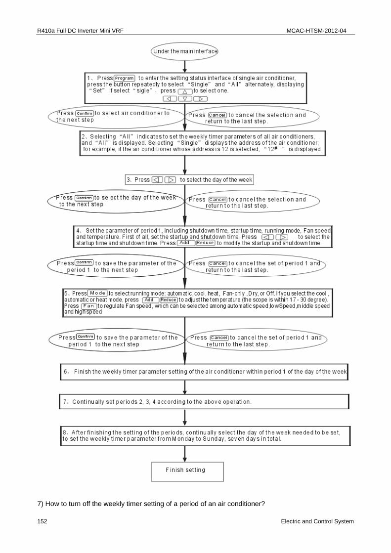
R410a Full DC Inverter Mini VRF MCAC-HTSM-2012-04
152 Electric and Control System
7) How to turn off the weekly timer setting of a period of an air conditioner?

MCAC-HTSM-2012-04 R410a Full DC Inverter Mini VRF
Electric and Control System 153
8) How to query the weekly timer setting parameter of the air conditioner?

R410a Full DC Inverter Mini VRF MCAC-HTSM-2012-04
154 Electric and Control System
9) How to start or shut down the weekly timer function of all air conditioner units?
10) How to adjust the system’s time?

MCAC-HTSM-2012-04 R410a Full DC Inverter Mini VRF
Electric and Control System 155

R410a Full DC Inverter Mini VRF MCAC-HTSM-2012-04
156 Electric and Control System
Note: There is always a time interval between 2 periods. This mean the period’s off time should not be
the same as the starting time of next work period. The least time interval should be 10 minutes, or the
units cannot work as our intentions.
Error codes and protection codes tables
Fault code Content
EF Other faults
EE Water level detection faults
ED Outdoor unit fault
EC Cleaning fault
EB Inverter module protection
EA Current of compressor is too large (4 Times)
E9 Fault of communication between main board and display board
E8 Wind blowing speed is out of control
E7 EEPROM error
E6 Detection of current direction alternating is abnormal
E5 T3 or T4 temp. senor of discharge of compressor fails down
E4 T2B sensor fails to work normally
E3 T2A sensor fails to work normally
E2 T1 sensor fails to work normally
E1 Communication fault
E0 Phase sequence disorder or loss of power phase
07#
06#
05#
04#
03# Communication mistake between centralized controller and PC(gateway)
02# Communication mistake between centralized controller and functional module
01# Communication mistake between centralized controller and network interface module
00# Communication mistake between network interface module and main control board
Protection code Content
PF Other protection
PE Reserved
PD Reserved
PC Reserved
PB Reserved
PA Reserved
P9 Reserved
P8 Compressor’s current is too large
P7 Voltage of power supply is too high or too low
P6 Pressure of discharge is too low
P5 Pressure of discharge is too high
P4 Temp. of discharge pipe is abnormal
P3 Temp. of compressor is abnormal
P2 Condenser high-temperature protection
P1 Anti-cool air or defrost protection
P0 Evaporator temperature protection

MCAC-HTSM-2012-04 R410a Full DC Inverter Mini VRF
Electric and Control System 157
Note: These two tables are the same with centralized controller CCM03.
2.4.3 General controller KJR-90B/M KJR-90B/M is a unified centralized controller, which allows us to control up to 16 indoor units simply and compactly. It commands the indoor unit to work at only 2 modes, cooling and heating. Besides this commanding, users could also modify the indoor units working mode by the remote wireless controller. This controller offers the controller functions only and is disable to bridge the units to the PC.
Centralized Control
Short press: Only turn ON/OFF the last time operated indoor units. Long press (3 seconds): Can Turn ON/OFF all indoor units.
Operation Mode Selection Switch (Cooling, Heating) Overall/mono-control the indoor units Sleep and memory function
If no operation to be conducted at the controller after 25 seconds, system would enter to sleep mode, all indicators are faded. Press any key to recovery the displaying.
Compatible with central control.
2.4.3.1 System configure MD-CCM09/E controller needs connecting it with other indoor units in a hand-in-hand way, which is the same connecting way with MD-CCM03. Either of the connecting ways below is available.

R410a Full DC Inverter Mini VRF MCAC-HTSM-2012-04
158 Electric and Control System
Description Names and Functions
1. Corresponding indoor unit tag Up to 16 indoor units be controlled by one centralized controller. If more than 16 indoor units, the operation would fail. Please set the indoor unit network address codes properly before using this controller. The following table show the relation between the tag and the corresponding network:
Air condition label A1 A2 A3 A4 B1 B2 B3 B4
Network address 0 1 2 3 4 5 6 7
Ari condition label C1 C2 C3 C4 D1 D2 D3 D4
Network address 8 9 10 11 12 13 14 15
The corresponding indication of the air conditioner reflects the working mode of its indoor unit, blue means cooling or air supply mode, red means heating mode. 2. Single indoor unit On/Off key Users could press this key to turn on or turn off the corresponding indoor unit. If the indoor units original mode is on, press this would turn it off. And vice versa. The interval between controlling 2 different unit should be more than 0.6 second. If less, the operation is invalid and of no use. Note: 1. If the red light flashes quickly, it means the corresponding indoor unit malfunctions.
2. If no one press the keys of the controller, the controller would turn itself into power saving mode, in which all the lights fade out. Press any key to stop this mode.
3. Unified mode setting key Press this key to set all the units’ mode. Only two mode can be set by this key. They are the cooling mode and the heating mode. The details of the two mode are as follows:
Temperature Fan Speed Key light
Cooling mode 20℃ Hi speed Blue
Heating mode 28℃ Hi speed Red
Note: The interval between these two mode alternating should be more than 6 seconds. If less, the alternating would be invalid and of no use. When the indoor unit’s working mode is changed by other device, such as remote controller, this centralized controller could detect, and change the corresponding units tag to show the actual running mode. 4. Unified On/Off key This key has 2 ways to send commands:

MCAC-HTSM-2012-04 R410a Full DC Inverter Mini VRF
Electric and Control System 159
Press for 3 seconds or more: To turn on or turn off all the indoor units that are connected to this controller. Press for less than 3 seconds: to turn on or turn off the single unit that we ever controlled most latterly. Note: If this key’s light flash quickly, it means that the EEPROM malfunctions. 2.4.3.4 Installation of KJR-90B/M Dimensions: 90*86*8mm
1) Please correct to connect the 2-core and 3-core shielded wire to imbed the wall. 2) When no less than 3 pieces of KJR-90B/M install nearly, please keep over 2m distance each other to avoid interfere.

R410a Full DC Inverter Mini VRF MCAC-HTSM-2012-04
160 Electric and Control System
Note: use screw to unpack the bottom cover of KJR-90B/M.
KJR-90B/M should be connect in a hand-in-hand way to the indoor units. It does not contains power transforming function, so this controller should obtain 5V power from the indoor units display panel. In fact, the display panel usually has a port in which two of pins are the 5V and GND. These two pins can be connect to the KJR-90B/M.
Note: KJR-90B/M uses a DC 5V power. Remember do not connect strong electricity power to KJR-90B/M, or the controller may blow.
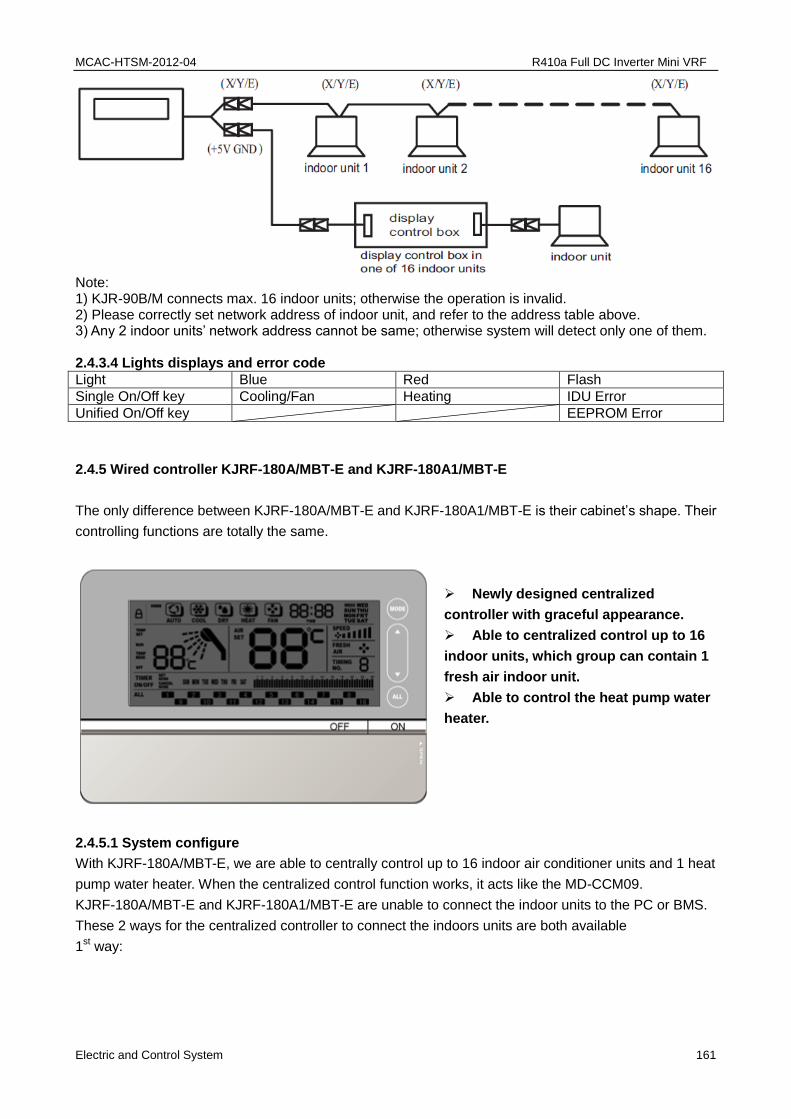
MCAC-HTSM-2012-04 R410a Full DC Inverter Mini VRF
Electric and Control System 161
Note: 1) KJR-90B/M connects max. 16 indoor units; otherwise the operation is invalid. 2) Please correctly set network address of indoor unit, and refer to the address table above. 3) Any 2 indoor units’ network address cannot be same; otherwise system will detect only one of them. 2.4.3.4 Lights displays and error code
Light Blue Red Flash
Single On/Off key Cooling/Fan Heating IDU Error
Unified On/Off key EEPROM Error
2.4.5 Wired controller KJRF-180A/MBT-E and KJRF-180A1/MBT-E
The only difference between KJRF-180A/MBT-E and KJRF-180A1/MBT-E is their cabinet’s shape. Their
controlling functions are totally the same.
Newly designed centralized
controller with graceful appearance.
Able to centralized control up to 16
indoor units, which group can contain 1
fresh air indoor unit.
Able to control the heat pump water
heater.
2.4.5.1 System configure
With KJRF-180A/MBT-E, we are able to centrally control up to 16 indoor air conditioner units and 1 heat
pump water heater. When the centralized control function works, it acts like the MD-CCM09.
KJRF-180A/MBT-E and KJRF-180A1/MBT-E are unable to connect the indoor units to the PC or BMS.
These 2 ways for the centralized controller to connect the indoors units are both available
1st way:

R410a Full DC Inverter Mini VRF MCAC-HTSM-2012-04
162 Electric and Control System
2nd
way:
To establish a steady network the following should be noted
The signal wire should be 3-core shielded wire and the wire should be provided by licensed
electricians.
To make signal transmission steady and to protect the facilities, the signal transmission wires should
not be near to the power line. An interval of 300mm-500mm should exist between these two kinds of
wires.
The signal wire of each network should be less than 1,200m.
The unit and the centralized controller should be connected hand-in-hand, which means that all the
units’ same port should be connected to a 3-core wire and the signal wire should be linear in
topology. Or else, the facilities could not work normally.
2.4.5.2 Description Name and Functions
Liquid Crystal Display:

MCAC-HTSM-2012-04 R410a Full DC Inverter Mini VRF
Electric and Control System 163
①The current time and date display
Display the date and the time.
②Operation lock display
Display whether the item is locked or not.
③Displays water heater area
Display the working status of the water heater.
④Displays event content settings
Display the content of the schedule.
⑤Displays operating status of the air-conditioner
Display whether the air-conditioner is running: LCD will be illuminated when the corresponding unit is
running, or flash slowly if it is not.
⑥Timing sequence
Display the timing sequence when setting the events.
⑦Display the state of the fresh air
Display the current work state of the fresh air handling unit.
⑧Display the set temperature of the air-conditioner
Display the current setting temperature of the corresponding air-conditioner.
Keys and functions

R410a Full DC Inverter Mini VRF MCAC-HTSM-2012-04
164 Electric and Control System
Mode button:
Press this button to change the indoor unit’s running mode. The changing sequence of the mode is as
follows, Auto/ Cool/Dry/Heat/Fan.
Temperature setting button:
Press this button to adjusts the setting temperature
ALL button:
Press this button to select all the indoor units.
ON/OFF button:
This button is used for turning on or turning off the water heater of the fresh air unit. The operation takes
effect after pressing the OK button.
OFF button:
Turn off all or one single air-conditioner.
ON button:
Turn on all or one single air-conditioner.
FRESH AIR button:
Press this key to select the fresh air unit. And then we can change the setting of the fresh air unit.

MCAC-HTSM-2012-04 R410a Full DC Inverter Mini VRF
Electric and Control System 165
TIME setting button:
Press this key to activate the time setting function.
OK button:
Press this button to confirm all the settings and deliver the signal the commands to the indoor units.
Water heater button:
Press this key to select the water heater. And then we can change the setting of the fresh air unit.
TIMING button:
Press this button to start setting the turning on and turning off schedule of the indoor unit.
UP and DOWN button:
Used for adjusting the setting temperature the air conditioner and the water heater. Users can lock or
unlock the keyboard by pressing the 2 keys synchronously.
CANCEL button:
Cancel the setting operation.
A single air-conditioner selection button:
Use this button to select the corresponding air conditioner.
FAN SPEED button:
Press this button to change the fan’s running speed.
2.4.5.3 Installation
Dimension:
KJRF-180A/MBT-E: 180*122*69mm
KJRF-180A1/MBT-E: 180*122*69mm
Upper Shell

R410a Full DC Inverter Mini VRF MCAC-HTSM-2012-04
166 Electric and Control System

MCAC-HTSM-2012-04 R410a Full DC Inverter Mini VRF
Electric and Control System 167
Base cabinet:
1) KJRF-180A/MBT

R410a Full DC Inverter Mini VRF MCAC-HTSM-2012-04
168 Electric and Control System
KJRF-180A1/MBT
Detaching the shell

MCAC-HTSM-2012-04 R410a Full DC Inverter Mini VRF
Electric and Control System 169
Wiring at the back
Available wiring diagram

R410a Full DC Inverter Mini VRF MCAC-HTSM-2012-04
170 Electric and Control System
2.4.5.4 Error and Diagnosis
1. If the centralized controller cannot detect the indoor units, and does not display the icons
. Check the wiring from the malfunction indoor unit to the
controller. Please make sure that the joint are tied steadily and the wiring obeys the hand-in-hand rule.
2. If the centralized controller cannot detect the water heater and does not display the shower icon ,
then check whether the P, Q, E of the controller is connected to the communicative line X, Y, E of the
water heater correctly. If it weren’t connected to the water heater directly, it would not display the shower
icon.
Note: KJRF-180A/MBT-E or KJRF-180A1/MBT-E does not display the error code of the indoor
unit.
2.4.6 Mode Lock Controller KJR-31B/E
KJR-31B/E is a wired centralized mode lock controller. With this device, we could lock the mode of all
the units connected to this controller to avoid mode conflict. When the mode conflict happens, e.g. some
indoor units request cooling and some heating, the outdoor unit could only work in either mode. As a

MCAC-HTSM-2012-04 R410a Full DC Inverter Mini VRF
Electric and Control System 171
result, some of the indoor units could not work. By adopting this device, we could consider the
environment and artificially determine whether the indoor units should work at cooling or heating mode.
New designed and graceful appearance
Compactly functions and friendly user
interface
Easy networking
Connected up to 64 indoor units
2.4.6.1 System configure
Mode lock controller KJR-31B/E is only a compact indoor unit centralized controller, which cannot bridge
the indoor units to the PC or BMS. Its network configuration is the same as MD-CCM09. The following 2
ways are both available.
1st
:
2
nd:
To establish a steady network the following should be noted
The signal cable and power cable of the central controller cannot be contained in the same cable tube. The distance between the signal cable tube and power cable tube shall be between 300mm -500mm at least.
The total signal cable length of the central controller shall not be exceed 1,200m. Make sure there is no joint in the middle of the shielded cable. If such a joint exists, use a socket to
connect it.

R410a Full DC Inverter Mini VRF MCAC-HTSM-2012-04
172 Electric and Control System
2.4.6.2 Description Names and Functions
Buttons and indication lights
1 Alarm light
When the alarm lights are on, malfunctions occur on the indoor units. Please check the indoor unit and
find the error code on the indoor unit’s display panel. After solving the problem, the ALARM light will fade
out.
2 COOL light
Push the mode switch leftwards to turn all the indoor units to cooling only mode and the COOL light will
be on. This light indicates that all the indoor units are running at cooling mode. Users can only set the
cooling parameter such as temperature and fan speed by other controller. If the user changes the units
to the heating only mode, the indoor unit displays mode conflict error code. And then the corresponding
unit turns off to prevent user’s environment from being more unsatisfying.
3 UNLOCK light
Push the mode switch to the middle of the controller and the UNLOCK light will be on. In this mode, all
the indoor units are freely to work at heating mode or cooling mode.
4 HEAT light
Push the mode switch leftwards to turn all the indoor units to heating only mode and the HEAT light will
be on. This light indicates that all the indoor units are running at cooling mode. Users can only set the
heating parameter such as temperature and fan speed by other controller. If the user changes the units
to the cooling only mode, the indoor unit displays mode conflict error code. And then the corresponding
unit turns off to prevent user’s environment from being more unsatisfying.
5 Mode switch
Mode switch is the only key on the controller. Slide this key and command all the indoor units to the
corresponding mode to avoid mode conflict.

MCAC-HTSM-2012-04 R410a Full DC Inverter Mini VRF
Electric and Control System 173
2.4.6.3 Installation
Dimension
Controlling wiring connection
Tie the screw

R410a Full DC Inverter Mini VRF MCAC-HTSM-2012-04
174 Electric and Control System
Assemble the front shell to the base
Connect the power adaptor to the controller
The power supply of the KJR-31B/E should be 220-240V 56/60Hz.

MCAC-HTSM-2012-04 R410a Full DC Inverter Mini VRF
Electric and Control System 175
Summary:
Comparison of the centralized controller
CCM03 CCM09 KJR-90B KJR-180A KJR-31B
Time display ─ ─ ─ ●
─
Keyboard locking ● ●
─ ●
─
Querying ● ●
─ ●
─
Swinging ● ●
─ ●
─
Error code display ● ●
─ ●
─
Error code light ─ ─ ●
─ ─
Backlight ● ●
─ ●
─
Schedule ─ ●
─ ─ ─
FOLLOW ME ─ ─ ─ ─ ─
Fan control ● ●
─ ●
─
Mode selection ● ● ● ● ●
Auto-start ● ●
─ ●
─
Mode lock ● ●
─ ─ ●
Address equipped ●
─ ─ ─ ─
Bride to gateway ●
─ ─ ─ ─
Max. units 64 64 16 16 64
Note: RS-485 is the very communicative way that our units use. In one complete system, several
RS-485 networks are built in side. For example, all the P, Q, E terminals compose a RS-485 network,
and all the X, Y, E another. So is the K1, K2, E, and the F1, F2, E ones. Each RS-485 network should be
connected in the hand-in-hand way. But the different RS-485 networks are separate.

R410a Full DC Inverter Mini VRF MCAC-HTSM-2012-04
176 Electric and Control System
2.5 Network Control System
Controller Model Description
Building gateway
MD-CCM08/E Building gateway connects to BACnet network for integrating to other BMS to realize air-conditioning management and control. It needn’t match Midea network system and PC.
Building gateway
MD-CCM07/E Connect VRV to your BMS via LonWorks, Other systems such as those for fire and crime prevention can be easily interlocked with Midea's unit.
Network control software
MDV-WLJKXT/E (V3.1)(Firebird)
The 3rd
generation network control software with Firebird data. Add network fee charge function and connect the outdoor unit CCM based on the No.2 generation network central control system. It may connect to 16 indoor unit CCM and 1024 indoor units, and also connect to 16 outdoor unit CCM and 128 refrigeration systems.
2.5.1 Building gateway MD-CCM08/E
MD-CCM08/E is a gateway to connect the indoor units and outdoor units to the BACnet. BACnet stands
for the Building Automation and Control Network. MD-CCM08/E gathers the information of the IDU and
ODU. Besides, MD-CCM08/E is able to send the command to the units.
Be able to bridge the indoor and outdoor units
to the BACnet protocol BMS.
Also be able to connect the indoor and outdoor
units only, without the BMS.
Contains 4 Groups of RS485 communication
ports and able to connect up to 256 indoor units or
128 outdoor units instead.
User can check the units’ status and change their settings via local network. Compatible with Firebird.
2.5.1.1 System configure MD-CCM08 is able to connect up to 4 groups of RS-485 communicative network. Each of the RS-485 networks contains up to 64 indoor units or up to 32 outdoor units. The input of MD-CCM08/E should be directly connected to the CCM03.

MCAC-HTSM-2012-04 R410a Full DC Inverter Mini VRF
Electric and Control System 177
If there are a few MD-CCM08 applied in the system, the MD-CCM08 can be connected to the HUB and then connected to the monitoring system and BMS.
Note: MD-CCM08 and the BMS computer must be at the same subnet address field. Or else, the device cannot work normally. The default address of CCM08 is set to be under the segment ―192.168.*.*‖. 2.5.1.2 Connecting ports and functions
CCM03
MD-CCM08 controller
BMS
RS485
TCP/IP
Outdoor units
Indoor units RS485
BACnet/IP protocol
Monitoring
system
HUB
HUB
Monitoring
system
BMS

R410a Full DC Inverter Mini VRF MCAC-HTSM-2012-04
178 Electric and Control System
MD-CCM08 has some kinds of connecting ports. EthernetA and LonWorks ports are used for further function designed and do not function by now. Ethernet B port is an Ethernet interface base on the BACnet network protocol. Connect this port with the BACnet HUB, then the device connect to the HUB can communicate with the MD-CCM08. 485A-485D: 4 groups of RS-485 communicative port. Each port can be connected to a MD-CCM08 via the ―F1, F2, E‖ terminals. 2.5.1.3 WEB access MD-CCM08 can offer web service, which allows users access the gateway from the local computer network. Type the address of MD-CCM08 in the explorer’s address field and users can view then MD-CCM08’s connecting status or change the working status of the indoor units. The interfaces are as follows:

MCAC-HTSM-2012-04 R410a Full DC Inverter Mini VRF
Electric and Control System 179
Note: The address ―192.168.234.234‖ is not constant in every CCM08. Users can find the default address in the package. Please modify the address of MD-CCM08 and make sure that the address is in the same subnet with the BMS computer before used. Moreover, the default administrator account to login the MD-CCM08 is ―Admin‖, default password ―123456‖. To save the air conditioner’s running data, an SD card is needed but not included in this product. Users can purchase one from the market. SD cards of different volume can save different periods of running data. Normally an SD card of 1 GB is able to save the data of more than 1 year. 2.5.1.4 Available BMS MD-CCM08 has a wonderful adaptability to the BMS. It can be connected to many company’s building management system software. We can get the mainly supporting BMS information from the table below:
Company BMS software Brand
1 SIMENS APOGEE
2 TRANE Tracer Summit
3 Honeywell Alerton
4 Schneider Andover
5 Johnson METASYS

R410a Full DC Inverter Mini VRF MCAC-HTSM-2012-04
180 Electric and Control System
2.5.2 Building gateway MD-CCM07/E
MD-CCM07/E is a gateway to connect the indoor units and outdoor units to the Lonworks network.
MD-CCM07/E helps other Lonworks devices gathering the information from the Midea central A/C, and
help setting the indoor units’ working mode. Compared with the MD-CCM07/E, MD-CCM08 needs a
computer and the 3rd
generation monitoring software.
Connect Central A/C system to LonWorks network. The core control module applies flash memory. Easily download the program on line. CCM07 applies nonpolar twisted pair lines, which makes connecting to LonWorks network easily.
2.5.2.1 System configure MD-CCM07 is a gateway from the 3
rd network control software to the LonWorks, which can gather all the
units’ information and control the indoor units. As a result, the indoor and outdoor units need firstly connecting to the computer to make a central monitoring system. The composition of the whole network is as follows:

MCAC-HTSM-2012-04 R410a Full DC Inverter Mini VRF
Electric and Control System 181
If there are a few MD-CCM07 devices to compose a LonWorks network, the LonWorks terminals of the MD-CCM07 are able to be connected in the hand-in-hand way. 2.5.2.2 Connecting ports and functions
COM port: This port should be connected to the computer’s COM port, using the RS-232 communicative standard. LonWorks: This port uses a removable connecting way to help user connect the LonWorks network conveniently. DC POWER: MD-CCM07 is an active gateway, so MD-CCM07 inquires a power supply of DC 24V. This port should be connected to the DC power adaptor.
2.5.2 Network control software MDV-WLJKXT/E(V3.1)(Firebird)
Please refer to ―installation and operation manual‖ of ―3rd
generation network control software‖.
2.6 Other Accessory
Assy. Model Description
Hotel card-inserter assy. MD-NIM05/E Match hotel card system to control the air conditioning.
Infrared sensor MD-NIM09/E Detects changes in infrared radiation which occur when there is movement by a person(or object).
Mode lock controller
2.6.1 Hotel card-insert accessories MD-NIM05/E and MD-NIM05/E-1
MD-NIM05/E and MD-NIM05/E-1 are mainly designed for the hotel card-insert system. It offers a smart
way to save energy and manage the air conditioners.
A smart way to save energy and money.
Cooperates with the hotel card-insert system.
Extra power supply is unnecessary.
Connected but insulate to the card-insert system
Easy to install.

R410a Full DC Inverter Mini VRF MCAC-HTSM-2012-04
182 Electric and Control System
The main difference between MD-NIM05/E and MD-NIM05/E-1 is that MD-NIM05/E-1 is able to record
the running status after power off and recover the unit to the previous running status. While MD-NIM05/E
runs the unit to the default starting status after power off.
2.6.1.1 Wiring
When the card is inserted, to turn on the air conditioner, the terminal COM1 and GND should be
connected or short. So the card-insert system should send the signal to the terminal COM1 and GND.
The wiring diagram should be as follows.
Wiring diagram:
Note:
1) An AC contactor or a delay is necessary to transform the signal.
2) Wiring assy. 1 connects the CN1 of hotel card-insert assy. to wired controller of air conditioner. 3) Wiring assy. 2 connects the CN2 of hotel card-insert assy. to display board and main control board of air conditioner indoor unit.
Note: COM1 and GND terminals should be short to work and not be connected to the power. The
electricity voltage over 5V will probably damage the device or get the device burnt and cause fire.
220V Power
220V
Hotel
Card
Insert
System
KM
MD-NIM05
CN2 CN1
COM1
GND
Indoor unit
display board
Wired
controller
L
N
AC contactor

R410a Full DC Inverter Mini VRF MCAC-HTSM-2012-04
182 Electric and Control System
2.6.1.2 Installation
Dimensions
Wires
2.6.1.3 Operation description
1) Connect 5-place terminal at fixed rated wired controller via 5 terminals: A, B, C, D, E.
2) Connect LCD at main control panel of indoor unit via terminals REV, C, D, E.
3) Upon wiring according to the wiring diagram in, Please power to the wired controller and switch on it.
When card has been inserted between in COM1 and GND, air conditioner is turn on and its operation
mode could be set, the director lamp at wired controller is light-up.
4) When no card has been inserted between in COM1 and GND (i.e. It not be short connected), the
ON/OFF button of wired controller cannot start air conditioner, but two beeps of air conditioner closed
down signals be giving out and no lamp is light-up at wired controller.
5) User must apply wired controller to turn on air conditioner and set operation modes every time power
is input. After then, operation modes of this performance would be memorized, although took off card
and then insert it on again, as long as power does not be cut off from main unit. i.e. air conditioner will

R410a Full DC Inverter Mini VRF MCAC-HTSM-2012-04
184 Electric and Control System
turn off when card is took off, unit will perform as per the last setting while inserting it on again.
Notice: the first start-up of main unit and mode setting must apply wired controller.
6) System can receive signal delivering from fixed rated wire controller (KJR-10B), and transits the signal
to indoor unit; it can also memorizes the latest ON/OFF information sending by wired controller (Timing
information be transited but memorized.)
7) Upon powered to card-inserter, transited signal defaults as unit shutdown. Once take off the card,
system will send signal of unit shut down twice; till to the next time card is inserted, system will not start
unit until 3 seconds later, because of memory information delivery.
2.6.2 Infrared Sensor MD-NIM09/E
CE-MD-NIM09/E is an infrared sensor, which is able to detect whether there is people nearby and auto
change the air conditioner back to running mode. This humanistic device helps making a comfortable
environment for the users and the turning down the conditioner automatically.
Be easy to install on the wall or ceiling.
Be with a wide detective angle up to 100°.
Detective distance is at least 4M, great sensibility.
Be powered from the indoor unit display panel. Safe and
extra power supply is unnecessary.
2.6.2.1 Wiring of MD-NIM09/E
The infrared sensor MD-NIM09/E contains a sensor and a control box. The control box helps connecting
the device to the wired controller and the indoor unit.

R410a Full DC Inverter Mini VRF MCAC-HTSM-2012-04
Electric and Control System 185
As above shown, the MD-NIM09/E has 3 connecting port.
CN1 is used for connecting the wired controller.
CN2 is used for connecting the indoor unit’s display panel.
CN3 is used for connecting the infrared sensor.
The switch S1 stands for:
Turn off the indoor units in 1 hour after users leave.
Turn off the indoor units in 0.5 hour after users leave.
Reserved.
2.6.2.2 How to use?
The general function of MD-NIM09/E is turning down the indoor unit automatically. So users should run
the indoor unit firstly and adjust the temperature, fan speed, etc, via the wired controller. Once set, users
do not need to turn down the indoor unit. The MD-NIM09 will turn it down automatically after the users
leave. Once the users come to the infrared sensor’s detective area, the MD-NIM09 turn the indoor unit
on and runs it at the status which is set previously..
2.6.2.3 Installation
Dimensions

R410a Full DC Inverter Mini VRF MCAC-HTSM-2012-04
186 Electric and Control System
Infrared sensor
Control box
Connecting and Assembly
Wires

MCAC-HTSM-2012-04 R410a Full DC Inverter Mini VRF
Electric and Control System 187