may the torque be with you. course notes · may the torque be with you. course notes last updated:...
TRANSCRIPT
2005 6.270 Autonomous RobotDesign CompetitionAttack of the Drones
May The Torque Be With You.
Course Notes
Last Updated: January 5, 2005
Massachusetts Institute of Technology
2005 Sponsors
We thank this year’s sponsors:a
• MIT Department of Electrical Engineering and Computer Science Financial funding, laboratory facilities, staff help and support.
• Analog Devices Donation of MEMS gyros and the time, help, and knowledge of Jack Memishian, Mark Nelson, and Howard Samuels.
• The Ford Motor Company Financial funding
• Gleason Research HandyBoard Controllers
• GM Financial funding
• Guidant Foundation Financial funding
• Hawker Energy Products, Inc. Lead-acid batteries, battery shrink wrap
• Intempco Gyro Interface Board
• IRobot Financial funding
• LEGO Dacta A/S, PITSCO PITSCO LEGO packs
• LEGO Denmark Bulk LEGO
iii
• LEGO Shop-at-Home LEGO boxed sets
• Microsoft Financial funding
• Newton Labs, Inc. Iteractive C
• Schlumberger Financial funding
• Sharp Electronics Distance sensors
And also, we extend special thanks to:
• Ron Roscoe and the lab staff With infinite patience, invaluable resources.
• Anne Hunter and the Course 6 Undergraduate Office A logistical powerhouse without whom we would truly be lost.
iv

Contents
2005 Sponsors iii
1 Introduction to 6.270 1
1.1 Staff . . . . . . . . . . . . . . . . . . . . . . . . . . . . . . . . . . . 2
1.2 Kits and Tools . . . . . . . . . . . . . . . . . . . . . . . . . . . . . 3
1.3 Electronic Communication . . . . . . . . . . . . . . . . . . . . . . . 3
1.3.1 Mailing Lists . . . . . . . . . . . . . . . . . . . . . . . . . . 3
1.3.2 Zephyr Instance . . . . . . . . . . . . . . . . . . . . . . . . . 4
1.4 Laboratory Facilities . . . . . . . . . . . . . . . . . . . . . . . . . . 4
1.4.1 6th Floor Laboratory . . . . . . . . . . . . . . . . . . . . . . 4
1.4.2 Other Facilities . . . . . . . . . . . . . . . . . . . . . . . . . 5
1.4.3 Etiquette . . . . . . . . . . . . . . . . . . . . . . . . . . . . 5
1.5 Credit Guidelines . . . . . . . . . . . . . . . . . . . . . . . . . . . . 6
1.6 Schedule . . . . . . . . . . . . . . . . . . . . . . . . . . . . . . . . . 7
1.6.1 Important Dates . . . . . . . . . . . . . . . . . . . . . . . . 7
1.6.2 Syllabus . . . . . . . . . . . . . . . . . . . . . . . . . . . . . 9
2 Attack of the Drones 11
2.1 The Table . . . . . . . . . . . . . . . . . . . . . . . . . . . . . . . . 12
2.1.1 General Table Information . . . . . . . . . . . . . . . . . . . 12
2.1.2 Table Description . . . . . . . . . . . . . . . . . . . . . . . . 12
2.2 Scoring . . . . . . . . . . . . . . . . . . . . . . . . . . . . . . . . . . 14
2.3 The Competition . . . . . . . . . . . . . . . . . . . . . . . . . . . . 15
v
2.4 Rules . . . . . . . . . . . . . . . . . . . . . . . . . . . . . . . . . . . 16
2.4.1 Period of Play . . . . . . . . . . . . . . . . . . . . . . . . . . 16
2.4.2 Kits . . . . . . . . . . . . . . . . . . . . . . . . . . . . . . . 17
2.4.3 Robots . . . . . . . . . . . . . . . . . . . . . . . . . . . . . . 17
2.4.4 LEGO . . . . . . . . . . . . . . . . . . . . . . . . . . . . . . 18
2.4.5 Software . . . . . . . . . . . . . . . . . . . . . . . . . . . . . 19
2.4.6 Non-LEGO parts . . . . . . . . . . . . . . . . . . . . . . . . 19
2.4.7 Placebos . . . . . . . . . . . . . . . . . . . . . . . . . . . . . 20
2.5 Extra Electronics . . . . . . . . . . . . . . . . . . . . . . . . . . . . 20
2.5.1 Electronic Modifications . . . . . . . . . . . . . . . . . . . . 20
2.5.2 The Sensor Store . . . . . . . . . . . . . . . . . . . . . . . . 21
2.5.3 30 Dollar Electronics Rule . . . . . . . . . . . . . . . . . . . 21
3 The Human Factor 23
3.1 Survival Tips . . . . . . . . . . . . . . . . . . . . . . . . . . . . . . 23
3.2 Teamwork . . . . . . . . . . . . . . . . . . . . . . . . . . . . . . . . 24
3.2.1 Planning . . . . . . . . . . . . . . . . . . . . . . . . . . . . . 24
3.2.2 Brainstorming . . . . . . . . . . . . . . . . . . . . . . . . . . 25
3.2.3 Constructive Conflict . . . . . . . . . . . . . . . . . . . . . . 25
3.2.4 Friends and Enemies . . . . . . . . . . . . . . . . . . . . . . 26
3.3 Implementation . . . . . . . . . . . . . . . . . . . . . . . . . . . . . 26
3.3.1 Division of Labor . . . . . . . . . . . . . . . . . . . . . . . . 27
3.3.2 Debugging . . . . . . . . . . . . . . . . . . . . . . . . . . . . 27
3.4 Contest Tips . . . . . . . . . . . . . . . . . . . . . . . . . . . . . . . 28
4 Electronic Assembly 29
4.1 Soldering . . . . . . . . . . . . . . . . . . . . . . . . . . . . . . . . . 29
4.1.1 Safety . . . . . . . . . . . . . . . . . . . . . . . . . . . . . . 30
4.1.2 Technique . . . . . . . . . . . . . . . . . . . . . . . . . . . . 30
4.1.3 Mounting Components . . . . . . . . . . . . . . . . . . . . . 32
4.1.4 Desoldering . . . . . . . . . . . . . . . . . . . . . . . . . . . 32
vi
4.2 Components . . . . . . . . . . . . . . . . . . . . . . . . . . . . . . . 33
4.2.1 Resistors . . . . . . . . . . . . . . . . . . . . . . . . . . . . . 33
4.2.2 Resistor Packs . . . . . . . . . . . . . . . . . . . . . . . . . . 34
4.2.3 Capacitors . . . . . . . . . . . . . . . . . . . . . . . . . . . . 35
4.2.4 Diodes and LEDs . . . . . . . . . . . . . . . . . . . . . . . . 36
4.2.5 Integrated Circuits . . . . . . . . . . . . . . . . . . . . . . . 36
4.3 Connectors . . . . . . . . . . . . . . . . . . . . . . . . . . . . . . . 37
4.4 Motors . . . . . . . . . . . . . . . . . . . . . . . . . . . . . . . . . . 38
4.5 Servo . . . . . . . . . . . . . . . . . . . . . . . . . . . . . . . . . . . 40
4.6 The Handy Board and Expansion Board . . . . . . . . . . . . . . . 41
4.7 Batteries . . . . . . . . . . . . . . . . . . . . . . . . . . . . . . . . . 41
5 Sensors 43
5.1 Digital Sensors . . . . . . . . . . . . . . . . . . . . . . . . . . . . . 43
5.1.1 Switches and buttons . . . . . . . . . . . . . . . . . . . . . . 44
5.2 Resistive Analog Sensors . . . . . . . . . . . . . . . . . . . . . . . . 45
5.2.1 Potentiometers . . . . . . . . . . . . . . . . . . . . . . . . . 46
5.3 Transistive Analog Sensors . . . . . . . . . . . . . . . . . . . . . . . 46
5.3.1 LED and Phototransistor . . . . . . . . . . . . . . . . . . . 47
5.3.2 Breakbeam Sensor Package . . . . . . . . . . . . . . . . . . . 48
5.3.3 Sharp Distance Sensor . . . . . . . . . . . . . . . . . . . . . 49
5.4 Gyroscopes . . . . . . . . . . . . . . . . . . . . . . . . . . . . . . . 50
6 Robot Construction 53
6.1 Design Concepts . . . . . . . . . . . . . . . . . . . . . . . . . . . . 53
6.2 The LEGO Technic System . . . . . . . . . . . . . . . . . . . . . . 54
6.2.1 LEGO dimensions . . . . . . . . . . . . . . . . . . . . . . . 54
6.2.2 Beams, Connectors, and Axles . . . . . . . . . . . . . . . . . 55
6.3 Bracing . . . . . . . . . . . . . . . . . . . . . . . . . . . . . . . . . 55
6.3.1 Drop Testing . . . . . . . . . . . . . . . . . . . . . . . . . . 56
6.4 Gears . . . . . . . . . . . . . . . . . . . . . . . . . . . . . . . . . . 56
vii
6.4.1 Gearboxes . . . . . . . . . . . . . . . . . . . . . . . . . . . . 57
6.4.2 Strange Gears . . . . . . . . . . . . . . . . . . . . . . . . . . 58
6.4.3 Chain Drives and Pulleys . . . . . . . . . . . . . . . . . . . 59
6.4.4 Efficiency . . . . . . . . . . . . . . . . . . . . . . . . . . . . 60
6.5 Drive Mechanisms . . . . . . . . . . . . . . . . . . . . . . . . . . . . 60
6.5.1 Differential Drive . . . . . . . . . . . . . . . . . . . . . . . . 61
6.5.2 Steering System . . . . . . . . . . . . . . . . . . . . . . . . . 62
6.5.3 Synchro Drive . . . . . . . . . . . . . . . . . . . . . . . . . . 62
6.5.4 Legs . . . . . . . . . . . . . . . . . . . . . . . . . . . . . . . 62
7 Robot Control 63
7.1 Control Systems . . . . . . . . . . . . . . . . . . . . . . . . . . . . . 63
7.1.1 Open Loop . . . . . . . . . . . . . . . . . . . . . . . . . . . 64
7.1.2 Feedback . . . . . . . . . . . . . . . . . . . . . . . . . . . . . 65
7.1.3 Open Loop Revisited . . . . . . . . . . . . . . . . . . . . . . 66
7.2 Sensors . . . . . . . . . . . . . . . . . . . . . . . . . . . . . . . . . . 67
7.2.1 Sensor Problems . . . . . . . . . . . . . . . . . . . . . . . . 67
7.2.2 Bouncing Switches . . . . . . . . . . . . . . . . . . . . . . . 68
7.2.3 Calibration . . . . . . . . . . . . . . . . . . . . . . . . . . . 68
7.3 Simple Navigation . . . . . . . . . . . . . . . . . . . . . . . . . . . 69
7.3.1 Wall Following . . . . . . . . . . . . . . . . . . . . . . . . . 69
7.3.2 Line Following . . . . . . . . . . . . . . . . . . . . . . . . . . 70
7.3.3 Shaft Encoders . . . . . . . . . . . . . . . . . . . . . . . . . 71
7.4 Timeouts . . . . . . . . . . . . . . . . . . . . . . . . . . . . . . . . 72
A IC commands for 6.270 73
A.1 Expansion Board: Motors, Analog Inputs, Digital Outputs . . . . . 73
A.2 Expansion Board: Servos . . . . . . . . . . . . . . . . . . . . . . . . 74
A.3 Using the RF Reciever . . . . . . . . . . . . . . . . . . . . . . . . . 74
B Expansion Board Assembly 77
viii

List of Figures
1.1 2005 6.270 Staff and email list . . . . . . . . . . . . . . . . . . . . . 2
2.1 2005 Contest Table Design . . . . . . . . . . . . . . . . . . . . . . . 13
4.1 Good and bad soldering technique . . . . . . . . . . . . . . . . . . . 31
4.2 Axial component mounting . . . . . . . . . . . . . . . . . . . . . . . 32
4.3 Resistor color code . . . . . . . . . . . . . . . . . . . . . . . . . . . 34
4.4 Resistor pack internal wiring . . . . . . . . . . . . . . . . . . . . . . 35
4.5 Identifying diode leads . . . . . . . . . . . . . . . . . . . . . . . . . 36
4.6 Top view of a 14-pin DIP . . . . . . . . . . . . . . . . . . . . . . . . 37
4.7 6.270 connector standard . . . . . . . . . . . . . . . . . . . . . . . . 37
4.8 Jig for motor assembly . . . . . . . . . . . . . . . . . . . . . . . . . 39
5.1 Digital Sensor Circuit . . . . . . . . . . . . . . . . . . . . . . . . . . 44
5.2 Switches and buttons . . . . . . . . . . . . . . . . . . . . . . . . . . 44
5.3 Resistive Analog Sensor Circuit . . . . . . . . . . . . . . . . . . . . 45
5.4 Potentiometers . . . . . . . . . . . . . . . . . . . . . . . . . . . . . 46
5.5 Transistive Analog Sensor Circuit . . . . . . . . . . . . . . . . . . . 47
5.6 LED and Phototransistor . . . . . . . . . . . . . . . . . . . . . . . . 47
5.7 Breakbeam sensor package . . . . . . . . . . . . . . . . . . . . . . . 48
5.8 Sharp Distance Sensor . . . . . . . . . . . . . . . . . . . . . . . . . 49
5.9 Mechanical configuration of the gyro board. . . . . . . . . . . . . . 51
6.1 LEGO Dimensions . . . . . . . . . . . . . . . . . . . . . . . . . . . 54
6.2 A Simple Braced Structure . . . . . . . . . . . . . . . . . . . . . . . 56
6.3 LEGO Gears . . . . . . . . . . . . . . . . . . . . . . . . . . . . . . 57
ix

6.4 A LEGO Gearbox . . . . . . . . . . . . . . . . . . . . . . . . . . . . 58
6.5 LEGO Pulleys . . . . . . . . . . . . . . . . . . . . . . . . . . . . . . 59
6.6 Popular Drive Arrangements . . . . . . . . . . . . . . . . . . . . . . 61
7.1 Open loop information flow . . . . . . . . . . . . . . . . . . . . . . 64
7.2 A robot trying to navigate with open loop control . . . . . . . . . . 64
7.3 Closed loop (feedback) information flow . . . . . . . . . . . . . . . . 65
7.4 A robot using feedback to navigate . . . . . . . . . . . . . . . . . . 66
7.5 A robot combining open loop and feedback control . . . . . . . . . 67
7.6 Wall following and a jammed robot . . . . . . . . . . . . . . . . . . 70
7.7 Line following with 3 reflectance sensors . . . . . . . . . . . . . . . 70
7.8 Shaft encoding using a LEGO pulley wheel . . . . . . . . . . . . . . 71
x
Chapter 1
Introduction to 6.270
6.270 is a hands-on, learn-by-doing course in which participants design and build a robot that will play in a competition at the end of IAP. Each team begins with a box of components from which members must produce a robot that can manipulate game objects on a playing field inhabited by an opponent. Unlike the machines in 2.007 Introduction to Design (formerly 2.70), robots in 6.270 are completely autonomous. Human intervention during the round is forbidden.
The goal of 6.270 is to teach students about robotic design by giving them the hardware, software, and information they need to design, build, and program their own robot. The concepts and applications taught in this class are related to various MIT classes (e.g. 6.001, 6.002, 6.004 and 2.007), however there are no formal prerequisites for 6.270. Students with little or no experience will find that they will learn everything they need to know from working with each other, being introduced to some material in class, and hacking on their robots.
6.270 is a very challenging course and requires participants to be willing to put in a real effort. Most students will spend in excess of one hundred hours building their robots. If you are willing to commit the time and energy needed for this class, you will have a great time and even learn something along the way.
So, prepare yourself for three and a half weeks of immersion into the world of robotics. Welcome to 6.270!
1

1.1 Staff
The 6.270 staff is composed of volunteers chosen from course alumni. You should feel free to approach these people for help or with any questions you might have. The staff consists of two groups of people, Organizers and Teaching Assistants, each with different responsibilities, but all of them will be available to assist you.
The Organizers are the people responsible for running the course. In addition to teaching and staffing the lab, they handle all the administrative duties, such as speak-ing with sponsors, ordering parts, defining the contest, and ensuring everything runs smoothly. A course the size of 6.270 requires a large amount of work and planning, and the Organizers have spent over a year preparing for this competition.
The Teaching Assistants (TAs) are recruited by the Organizers to assist in teaching the course. They work primarily during IAP and their job description requires that they help teach recitations, staff the lab, and build demonstration robots and placebos. They are often also called upon by the Organizers to assist in certain tasks.
Organizers and TAs receive very little compensation for the work they do. They are here only because they love 6.270 and want others to have the same opportunity to enjoy it as they did. In return, the staff asks only that you put in the time and effort necessary to get as much as possible out of the course. If you enjoy your experience in this course and would like to see it continue to be offered, please consider joining the staff in future years. It is only through the continued enthusiasm and selflessness of course alumni that 6.270 is able to remain the most popular student-run activity at MIT.
As we compile it, we will be placing more information, including pictures, lab hours, and skill lists (who to contact for help with a certain aspect of the contest) on the server.
2

1.2 Kits and Tools
The 6.270 kit, valued at about $1500, is yours to keep at the end of the contest. This is made possible by financial support from the EECS department and the course’s commer-cial sponsors. If your team does not present a robot to the Organizers at the qualifying round of the competition, or if you are asked to leave the course, you will be required to forfeit the kit back to the EECS department. Teams who do not return the entire kit when asked will be charged the full $1500 through the office.
There are tools available for in-lab electronics work, but these resources will probably be over-burdened, especially towards the end of IAP. Therefore, in addition to the kit, a set of tools will be reserved for purchase by your team. This set will include all of the tools necessary for building your robot (i.e. soldering iron and stand, wire cutters, long nose pliers, etc.). You will be expected to either provide your own electronic assembly tools or purchase them from the Organizers. Since 6.270 buys in bulk, the prices of the tools will be lower than what you can find elsewhere. It is very important that you have a good set of your own tools to work with.
1.3 Electronic Communication
Due to the rapid pace of the course, information must often be distributed quickly to large numbers of people. To accomplish this, 6.270 primarily uses electronic communication.
1.3.1 Mailing Lists
Email is the primary medium through which important announcements are sent. Since this information must often reach the entire class on short notice, participants are en-couraged to check their email daily.
3

1.3.2 Zephyr Instance
The course uses a zephyr instance for 6.270-related discussion. It is meant to be a forum where participants can help each other with problems they are having. The staff does not officially monitor the discussion, but will often be online to help out.
To receive zephyrs on the instance, you should type at the server prompt: zctl add message 6.270 "*"
To send a message to the instance: zwrite -i 6.270
If you wish to remove yourself: zctl delete message 6.270 "*"
1.4 Laboratory Facilities
During the course of constructing your robot, you will have access to workspaces, tools, and computers in the following areas:
1.4.1 6th Floor Laboratory
The 6th floor lab is the center of activity for the course. This lab is supervised by the 6.270 staff, and other teams will be present to share ideas with. Among the useful facilities in this lab are workbenches for building your robot, computers for programming, and two contest tables for testing.
The lab will be open and staffed from 9 am to 11:45 pm on weekdays and noon to 10 pm on weekends. During the final few days of the course, the lab may be open 24 hours a day.The phone line needs to be kept available for official use, and the staff is too busy to run
a personal messaging service. If you order food to eat elsewhere, from the lab phone,make sure you can be found.
Since this lab is on loan to 6.270 by the EECS department, you will be expected to be on your best behavior. Do not touch equipment not explicitly meant for 6.270 use and treat the lab staff with respect. Be aware that when the equipment desk workers are
4
If you need to call the lab, you can, but please do not place or receive personal calls too often.
ready to close the lab, you should be going out the door. Abuse of the lab or its staff will not be tolerated.
1.4.2 Other Facilities
If you have the appropriate cable, you can also program your robot at most server workstations. You may not, however, solder, cut, or glue in the clusters, and you must be respectful of others when operating your robot, since robots can be quite loud. Violations of server etiquette will result in severe action by the 6.270 Organizers.
Since the course software is available for a number of computer platforms, some students choose also to program their robots from their own computers. Teams with access to laptops may find this option especially useful even when working in the lab, since it frees them from waiting for the lab computers. Unfortunately, due to the staff’s limited amount of time, technical support for personal computers must take low priority with respect to other duties.
1.4.3 Etiquette
When working in the lab or at the server ,you will be expected to be respectful to those around you. The following guidelines should be adhered to at all times:
1. Noise. Your robot will be quite noisy. When working at the server , please minimize the operation of your robot. If others are disturbed by the noise, stop running the robot or move to another cluster.
2. Hardware. Do not solder, cut, or glue any hardware in the clusters or around the computers in lab. Debris can get lodged in the keyboards and damage the computer. Furthermore when working on the lab benches with solder or glue ensure you have carboard underneath your working area to prevent damage to the tables, failure to do so may result in the loss of lab privileges.
3. Tidiness. Do not leave your stuff laying around lab. The lab will be crowded and people need places to work. Your team should try to limit the area that it uses to two workbenches, or one if the lab is very crowded.
4. Locked Screens. At the server, donot leave your screen locked for more than 20 minutes. In lab, any computer with a locked screen will be logged off. Repeated violations will result in a loss of computer privileges.
5. Multiple Machines. Do not log on at multiple machines. When the lab is crowded, please try also to minimize the number of people on your team who are logged on.
5
The lab does not have enough computers to support everyone being logged on at once.
Violations of the rules of etiquette will not be tolerated and will be dealt with severely. If the Organizers receive complaints about any team causing a disturbance in the server clusters, that team will be required to return its kit and will be thrown out of the course. Repeated violations in lab will be dealt with by the Organizers on a case by case basis.
1.5 Credit Guidelines
6.270 is offered as MIT subject 6.185 for 6 units of Pass/No Record credit with the further option to receive 6 Engineering Design Points (EDPs). Taking the course for credit is optional, but you will be doing a lot of work anyway. Receiving credit will give you formal recognition on your transcript in addition to the academic credit.
It is the job of the instructors to ensure that credit is properly awarded to students deserving of it. In order to properly evaluate your performance, it is necessary that you report your work. The credit requirements are structured to allow your instructor to authorize credit and also assist you in the learning process.
The following guidelines must be completed in order to receive 6 units of academic credit, and if desired, 6 EDPs:
• Robot Web Page. Each team must create a web page for its robot before im-pounding. The page should present information about the robot suitable for display to the general public. It should focus on the overall design and strategy of the robot including an explanation of anything particularly clever or unique. Each individual desiring credit must help with the work.
• Assignment Completion. Seven assignments will be handed out during the first two weeks of the course. These assignments were made to help guide participants in making effective and competitive robots. Participants wanting credit are expected to complete the assignments on-time. Failure to complete the assignments on time will result in gradual penalties ultimatly resulting in forfeiture of the competition.
• Completed Robot. The team must “show” a robot at the qualifying round. Its functionality, or lack thereof, has no effect on the team’s members receiving credit for the work they have done.
These requirements are meant to be useful to both you, the class participant, and the instructors, who will be authorizing credit. You should have no trouble receiving credit if all of the requirements are satisfied. If you have any questions about your standing in the subject at any time, feel free to ask your instructor for feedback.
6
Please note that due to the scheduling constraints of the Registrar and the sanity of the Organizers, there is no leeway on any of the due dates. Please do not ask for extensions.
1.6 Schedule
The schedule of activities between the start of 6.270 and the evening of the contest is very tight. You will have to work steadily and with determination to produce a working robot by the end of the course. To assist you in this endeavor, a number of class meetings will be held to teach the course material. It is recommended that you attend as many of these sessions as possible.
• General Lectures. Lectures will be held during the first week of the course to introduce you to the basics of robotics. These lectures are meant to provide you with an overview of the information necessary to create a working 6.270 robot.
• Laboratory Sessions. Staff members will be present in the 6th floor lab to assist you in the construction of your robot. One of the goals of 6.270 is to encourage interaction, and the lab is a great place to share ideas with others and experiment with new ideas.
• Workshops. During the first two weeks of the course, workshops will be taught by experienced staff members. These workshops will cover many aspects of the course, from soldering to programming to construction. They are planned to help reinforce the material learned in lecture.
1.6.1 Important Dates
While it is important that you attend all of the scheduled 6.270 events, the following meetings and deadlines are mandatory and should not be missed:
• Parts Sorting Session - Sunday, January 2nd, 2 pm,
Each team must provide one person-hour of manual labor to help sort out the kit parts. Usually, this session is a lot of fun as you get to meet other people in the class and see all the kit parts.
• Lecture 1 - Monday, January 3rd, 10 am
Each team must have at least 50% of its members present to claim the kit.
• Assignment 1 - assigned Monday, January 3rd, due Tuesday, January 4th
7

• Assignment 2 - assigned Tuesday, January 4th, due Thursday, January 6th
•
•
Assignment 3
Assignment 4
- assigned Wednesday, January 5th, due Friday, January 7th
- assigned Friday, January 7th, due Tuesday, January 11th
•
•
Assignment 5
Assignment 6
- assigned Tuesday, January 11th, due Friday, January 14th
- assigned Friday, January 14th, due Tuesday, January 18th
• Assignment 7 - assigned Tuesday, January 18th, due Friday, January 21st
• Mock Contest - Friday, January 21st, 7 pm
This is a good way to familiarize yourself with the contest proceedings, as well as find any bugs in your robot as you compete against other teams. Even if your team’s robot is not ready, you can observe the strategies other teams have used. This contest is optional and not required for completion of this course. Many teams find it useful to make mock contest competition a goal to strive for.
• Contest, Qualifying & Seeding Rounds - Sunday, January 23rd, 10 am &
2pm
These are the first two official rounds of competition. Robot performance in these two rounds determine its seeding rank for the final rounds. These rounds do not count toward the robot’s double elimination. This event is open to the public. See Section 2.3 for more details on the contest rounds.
• Robot Impounding - Tuesday, January 25th, 5 pm
All work on robots must cease and robots will be impounded. During this time, robots will be inspected for rule violations.
• Contest, Double Elimination Rounds - Wednesday, January 26th, 10 am &
2pm
All qualifying robots will compete in this round. This event is open to the public. These two rounds count toward a robot’s double elimination score as well as its seeding rank. See Section 2.3 for more details on the contest rounds.
• Contest, Final Rounds - Wednesday, January 26th, 6 pm
The main competition. Robots will compete until a winner is decided. This event is open to the public. See Section 2.3 for more details on the contest rounds.
• Lab Cleanup - Thursday, January 27th, 2 pm
Attendance at this session is mandatory. Each team must provide one person-hour of manual labor to help clean up the lab, so we can return it to 6.111 the way we found it.
8

1.6.2 Syllabus
Lectures and workshops will be the primary way that material is taught, so attendance at these sessions is very important. Workshops run on the hour from 1-3 pm and 7-9 pm. The following topics will be covered:
• Lecture 1 - Welcome Monday, January 3rd, 10 am
Introduction to 6.270, Contest Rules, Fundamentals of LEGOs, kit distribution.
• Workshop 1 - Basic Techniques of LEGO Assembly Monday, January 3rd, and Tuesday, January 4th
Bracing is a key element in keeping your robot together during the contest. Find out how to do it effectively.
• Workshop 2 - Motor Mounting and LEGO Gearboxes Monday, January 3rd, and Tuesday, January 4th
Learn how to properly make a LEGO gearbox that works smoothly and efficiently. Learn more about gear ratios, and how to connect your motors to your gearbox.
• Lecture 1.5 (Optional) - Crash Course in C Tuesday, January 4th, 7 pm
Come to this lecture to learn and review the basics of C programming.
• Lecture 2 - Building the Basic Robot Wednesday, January 5th, 10 am
Electronics Review; The HandyBoard; Sensors & Actuators; Interactive C
• Workshop 3 - Electronic Assembly Wednesday, January 5th, and Thursday, January 6th
In 6.270 you will have to solder several electronic components for your robot. Learn the basics of PCB assembly and soldering for small electronics. During this workshop you will have the opportunity to solder your battery recharger.
• Workshop 4 - Code & Sensors I: Basic Control and Robot Skills Wednesday, January 5th, and Thursday, January 6th
In this workshop you will learn how the HandyBoard communicates with its sensors and actuators. Get an introduction to IC and learn fundamental ways to make your robot move and turn. If you feel you do not know much about C at all, be sure to attend the Crash Course in C Tuesday night.
• Lecture 3 - Advanced Techniques Friday, January 7th, 10 am
Advanced Sensors; Finite State Machines; Control
9

• Workshop 5 - Servos, Sensors, and Shaft Encoders Monday, January 10th, and Tuesday, January 11th
Your robot cannot do anything useful without some knowledge of its external surroundings. Your robot will also need mechanisms for which it can navigate swiftly and accurately around the contest table. Learn how these parts in your robotics kit can help your robot move the way you want it to move. Find out which sensors work best for your robot’s needs, and how to keep accurately track of how far or at which angle your robot has been moving. Also discuss how to use these unique parts in some more creative ways.
• Workshop 6 - Advanced LEGO Mechanisms and Parts Monday, January 10th, and Tuesday, January 11th
Every year many of the more unique pieces of your LEGO kit are left unexplored and unused. Learn some interesting applications of your stranger LEGO pieces, and how they can help your robot do task-specific motions.
• Workshop 7 - Code II: Advanced Techniques
Assignment handed out: Friday, January 7th
The code for your robot plays a crucial role in your robot’s ability to win. Learn the value of good coding practices by observing robots with identical hardware trying to do the same task in different ways. Learn about error recovery techniques and how to achieve robustness in your code and strategy. This workshop will not be run as a class like the others. Instead, an assignment will be handed out. Teams are encouraged to work on this assignment and go to the office hours for feedback or help.
10
Chapter 2
Attack of the Drones
A short time from now, in a galaxy very close by, the masses are in unrest.
The non-trademark-infringing Gedi Knights Council, droid masters, guardians
of the free world, and practitioners of the ancient interlocking plastic brick
arts, have suffered a huge loss. Their former leader, Chin-wala-kane-ra, bet
ter known as ”Chuck”, has transcended to a higher plane of existence, and
no longer will be around to keep the masses in check. An election will be held
tonight to determine ”Chuck’s” replacement, for without a leader, the Gedi
Knights will be powerless to stop the ever-growing threats of all-nighters in
lab, freshman showering, and Red Sox fans.
Through many years of meditation and practice, the Gedi Knights have de
veloped a keen ability to affect the subconsciouses of the weak-minded masses.
These abilities, colloquially known as ”mind tricks”, are channeled and focused
using autonomous mechanical contraptions, colloquially known as ”robots”.
As part of their droid master training, each Gedi Knight shall build a robot
companion and train it to serve as their vehicle for power and influence.
Soon it will be Election Night. The robots will have only one mission - to
influence as many votes as possible for thier Gedi Master. Faithful as an R2
unit and about as well trained as a womp rat, these robots shall be set in their
tasks. Strength of will, speed of mind-tricks, and reliability of gear trains will
be tested. And one droid shall triumph above all, ushering in a new era of
leadership for the Gedi Council.
11

2.1 The Table
2.1.1 General Table Information
The layout of the contest table is shown in Figure 2.1. All measurements are approximate, although the only official measurements are those of the actual tables. The tables also have seams, where sections of the table physically meet. Make sure your robot is capable of facing the imperfections of the board.
Also, do not rely on the texture of the contest table surface. The tables will be steadily worn down over IAP, and some sections may repainted before the final contest. In addition, the tables were made during the summer, and therefore their surfaces may have warped slightly by the time of the contest. A properly designed robot should be able to surmount these problems.
2.1.2 Table Description
The table is flat. The entire 6’ x 8’ area is surrounded by a 2” wall on all four sides. The surface of the table is white, but there are a number of 2” wide black lines that can be used for navigation. For the lines running east-west along the table, there are 18” between the center of the line and the wall. The lines running north-to-south across the middle of the table have their centers at 6”, 3’ and 5’4” from the 8’ walls. The center line goes through the middle of the two starting areas
On the two 8’ sides of the table there are slots 2’ long and 1.5” in height.
There is one vertical obstacle on the board, represented on the figure by the blue rectangle. It is 2”x18” and stands 10” tall. This obstacle is fixed and your robot will not be able to move or destroy it.
There are 44 (22 red and 22 green) approximately 1” diameter balls on the table. They are arranged in groups of four and represent groups of Gedi Council Voters. The balls are placed at the corners of an 8” x 8” square. There is a set of balls in the center of the table, stradling the barrier. Each slot on the side of the table has a set of balls on eaither side of it. The center scoring areas each have a set of balls in front of them. Finally the corner scoring areas each have a set of balls oppisit the outer corner.
There are shallow divots on the table for all of the balls to rest on. Balls may be pushed around, picked up, knocked off the table, or otherwise moved by the robot.
Robots begin in the center of the table, with the white robot starting on the black cross and the black robot starting on the white cross. The presence/lack of the solid 8”x 8” black squares in each starting area assists the robot in determining which side it is on.
12
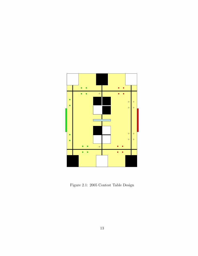
Figure 2.1: 2005 Contest Table Design
13
2.2 Scoring
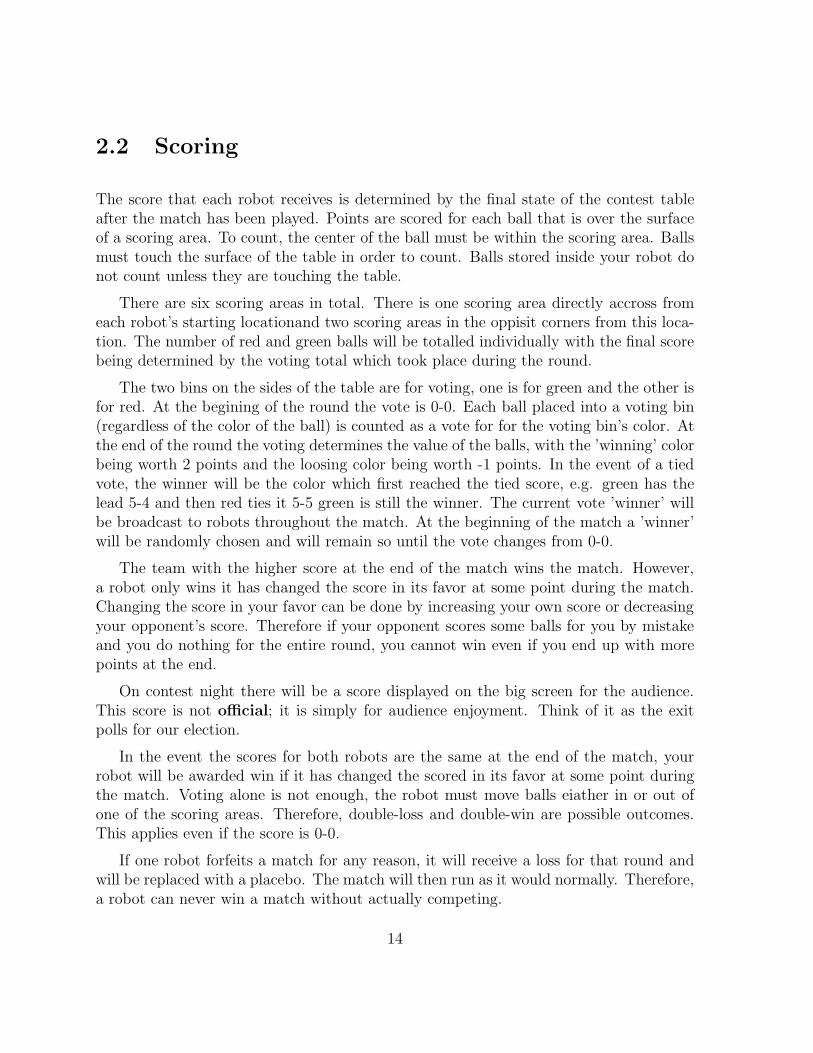
The score that each robot receives is determined by the final state of the contest table after the match has been played. Points are scored for each ball that is over the surface of a scoring area. To count, the center of the ball must be within the scoring area. Balls must touch the surface of the table in order to count. Balls stored inside your robot do not count unless they are touching the table.
There are six scoring areas in total. There is one scoring area directly accross from each robot’s starting locationand two scoring areas in the oppisit corners from this location. The number of red and green balls will be totalled individually with the final score being determined by the voting total which took place during the round.
The two bins on the sides of the table are for voting, one is for green and the other is for red. At the begining of the round the vote is 0-0. Each ball placed into a voting bin (regardless of the color of the ball) is counted as a vote for for the voting bin’s color. At the end of the round the voting determines the value of the balls, with the ’winning’ color being worth 2 points and the loosing color being worth -1 points. In the event of a tied vote, the winner will be the color which first reached the tied score, e.g. green has the lead 5-4 and then red ties it 5-5 green is still the winner. The current vote ’winner’ will be broadcast to robots throughout the match. At the beginning of the match a ’winner’ will be randomly chosen and will remain so until the vote changes from 0-0.
The team with the higher score at the end of the match wins the match. However, a robot only wins it has changed the score in its favor at some point during the match. Changing the score in your favor can be done by increasing your own score or decreasing your opponent’s score. Therefore if your opponent scores some balls for you by mistake and you do nothing for the entire round, you cannot win even if you end up with more points at the end.
On contest night there will be a score displayed on the big screen for the audience. This score is not official; it is simply for audience enjoyment. Think of it as the exit polls for our election.
In the event the scores for both robots are the same at the end of the match, your robot will be awarded win if it has changed the scored in its favor at some point during the match. Voting alone is not enough, the robot must move balls eiather in or out of one of the scoring areas. Therefore, double-loss and double-win are possible outcomes. This applies even if the score is 0-0.
If one robot forfeits a match for any reason, it will receive a loss for that round and will be replaced with a placebo. The match will then run as it would normally. Therefore, a robot can never win a match without actually competing.
14

2.3 The Competition
The competition will be a double elimination tournament held over the course of two days. Robots compete head to head in successive rounds until they lose twice. When all but one robot has been eliminated, that robot will be crowned champion.
This year, we have changed the way pairings are done in each round. In each round, if there are an odd number of robots, the robot that has scored the most cumulative points will face a placebo. After that robot is paired, the robot with the next highest cumulative score is paired with the robot with the lowest cumulative score, and so forth. Ties are resolved randomly. Note that this system is only used for deciding what opponent each robot will face – the order in the round and the side of the table are still randomly selected.
Every round of the competition is used for seeding – two rounds on Monday, two rounds on Thursday morning, and each round on Thursday evening.
All rules are subject to change at any point during competition, at the discretion of the Organizers. This power will be used sparingly.
• Contest, Assignments. Failure to complete assignments in a timely manner, or at all, can and will result in the awarding of losses to a team’s robot. These losses will carry over into competition day and if a team has been awarded two they will be eliminated prior to the first round of the day. Exact details on will be given in lecture.
• Contest, Qualifying Rounds. The first two rounds of the contest serve as qualifying and seeding rounds. If a robot demonstrates the ability to score points, regardless of whether it wins or loses, it will be allowed to proceed to the competition rounds on Thursday. If it does not, modifications may be made, and it may attempt to qualify in lab against a non-competitive placebo. If it cannot score points against the placebo, it will not qualify for the rest of the contest. Robots may qualify until impounding. Losses to opponents during these rounds do not count towards a robot’s elimination.
For the sake of efficiency, we will be publishing a schedule for the round matchups as soon as one is available. We promise that each robot will not be asked to compete until the time that is posted. If a team is not present when we are ready to start the match, the team automatically forfeits. This does not count against a team in elimination, only in seeding.
• Contest, First and Second Rounds. Only qualifying robots may compete in the first and second rounds. If a robot loses in both the first and second rounds, it will be eliminated from the competition.
15

For the sake of efficiency, we will be publishing a schedule for the round matchups as soon as one is available. We promise that each robot will not be asked to compete until the time that is posted. If a team is not present when we are ready to start the match, the team automatically forfeits. This does count against a team in elimination; if your team misses both of its starts, you will be eliminated from the competition.
• Contest, Final Rounds. This is the main competition that everyone comes to see. Robots will compete until all but the winner have been eliminated. Once two teams remain in the contest, all previous records will be erased and three rounds will be run. The team with more wins in the three rounds wins the competition. If both teams have the same number of wins, the winner will be decided by cumulative points scored in the final three rounds. If both teams have the same number of points, both teams will be declared winners.
2.4 Rules
The following rules of play are meant to ensure a fair and interesting contest. Contestants are responsible for knowing and following these rules. If you have any questions or doubts about the legality of your robot, please ask the Rules Committee for an official ruling.
2.4.1 Period of Play
1. Prior to reaching the table contestants will be given a color swatch for thier robot which they will place on what they have designated as the ’center’ of their robot. During the contest if the color swatch is deliberatly covered or obscured the team will forfiet the match.
2. The contestants will have 60 seconds to set up their robot. The team will be notified of their robot start orientation before the set up period. The robot must be place with the side marked ’front’ facing the start orientation direction. The robot must be placed such that no part of the robot is outside the square starting area.
3. After the set up period has elapsed, the judge ask the contestants to arm their robots. The contestants arm their robot (probably by pressing a button), and must step away from the table.
4. Robots may not supply power to their actuators at this point. If a robot does, it has false-started. Also, if a team takes more than the alotted 60 seconds for setup, this counts as a false start. If a robot false-starts twice, it forfeits that match.
16
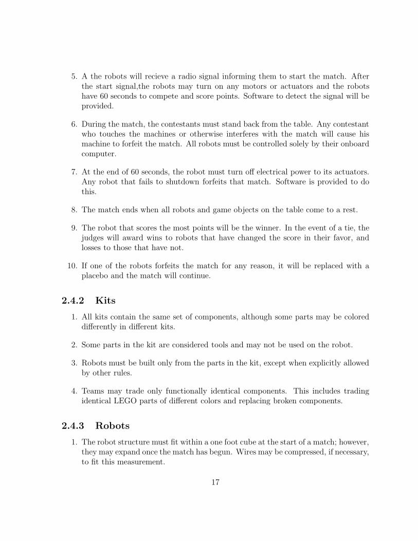
5. A the robots will recieve a radio signal informing them to start the match. After the start signal,the robots may turn on any motors or actuators and the robots have 60 seconds to compete and score points. Software to detect the signal will be provided.
6. During the match, the contestants must stand back from the table. Any contestant who touches the machines or otherwise interferes with the match will cause his machine to forfeit the match. All robots must be controlled solely by their onboard computer.
7. At the end of 60 seconds, the robot must turn off electrical power to its actuators. Any robot that fails to shutdown forfeits that match. Software is provided to do this.
8. The match ends when all robots and game objects on the table come to a rest.
9. The robot that scores the most points will be the winner. In the event of a tie, the judges will award wins to robots that have changed the score in their favor, and losses to those that have not.
10. If one of the robots forfeits the match for any reason, it will be replaced with a placebo and the match will continue.
2.4.2 Kits
1. All kits contain the same set of components, although some parts may be colored differently in different kits.
2. Some parts in the kit are considered tools and may not be used on the robot.
3. Robots must be built only from the parts in the kit, except when explicitly allowed by other rules.
4. Teams may trade only functionally identical components. This includes trading identical LEGO parts of different colors and replacing broken components.
2.4.3 Robots
1. The robot structure must fit within a one foot cube at the start of a match; however, they may expand once the match has begun. Wires may be compressed, if necessary, to fit this measurement.
17

2. All parts of a robot must be connected via LEGO. Robots may not separate or have a tendency to break into multiple parts.
3. Decorations may be added to a robot provided they perform only an aesthetic function, and not a structural one.
4. Robots may not intentionally damage, or attempt to damage, the opponent robot, its microprocessor board.
5. No parts or substances may be deliberately dropped onto the playing field.
6. Any robot that appears to be a safety hazard will be disqualified from the competition.
2.4.4 LEGO
1. Only LEGO parts may be used as robot structure.
2. A robot’s structure may not be altered after impounding. Repairs may be made between rounds if time permits.
3. LEGO pieces may not be modified in any way, with the following exceptions:
• The LEGO baseplate may be modified freely.
• LEGO pieces may be modified to facilitate the mounting of sensors and actuators. However, such modification cannot be structural.
• LEGO pieces may be modified to perform functions directly related to the operation of a sensor. For example, holes may be drilled in a LEGO wheel to help make an optical shaft encoder. Such modifications cannot be structural.
4. LEGO pieces may not be joined by adhesive.
5. Lubricants of any kind are not permitted.
6. Rubber band or tape may be applied to LEGO wheels and treads to alter the coefficient of friction. See Section 2.4.6 for more details on the use of rubber bands.
7. Wheels may be stuffed with any material within reason. Students usually stuff them with rubber bands, LEGO, or hot glue. Double-check with an Organizer before using another material.
18

2.4.5 Software
1. A robot’s program cannot be altered after impounding.
2. In the event of a memory failure, a copy of the robot’s program may be downloaded from an official computer between rounds. The program available for download will be the version submitted on impounding. Contestants are not permitted to download any code to the robot from their own computer or any other computer.
3. A robot may not be told its position or be given information about its opponent. It may only deduce this information after the match has begun.
2.4.6 Non-LEGO parts
1. Sensors, actuators, and other Non-LEGO parts may not be used as structural components.
2. Non-LEGO parts may be attached to no more than five LEGO parts.
3. Non-LEGO parts may be freely modified to assist in their operation.
4. A reasonable amount of cardboard, other paper products, and tape may be used for the purpose of creating optical shields for sensors.
5. Wire may only be used for electrical purposes and may not be dragged on the playing surface. Wires that extend outside of the robot should be tied back.
6. String may be used to convey force between moving parts (i.e. pulley systems) but may not be used for structural support. String may also be used to stuff tires for stiffening purposes.
7. Extraneous components may not be added to a robot for the purpose of adding weight.
8. Rubber bands cannot be used for structural support. Only thin rubber bands that are supplied by the organizers (#16 and #32) may be used. Rubber bands may be used only for the following purposes:
• Rubber bands may be used to store energy to affect the motion of moving parts. Rubber bands used for this purpose must be touching at least one piece of LEGO. LEGO pieces connected by a single rubber band or a chain of two rubber bands must move relative to each other.
• Rubber bands may be used to stuff tires for stiffening purposes.
19
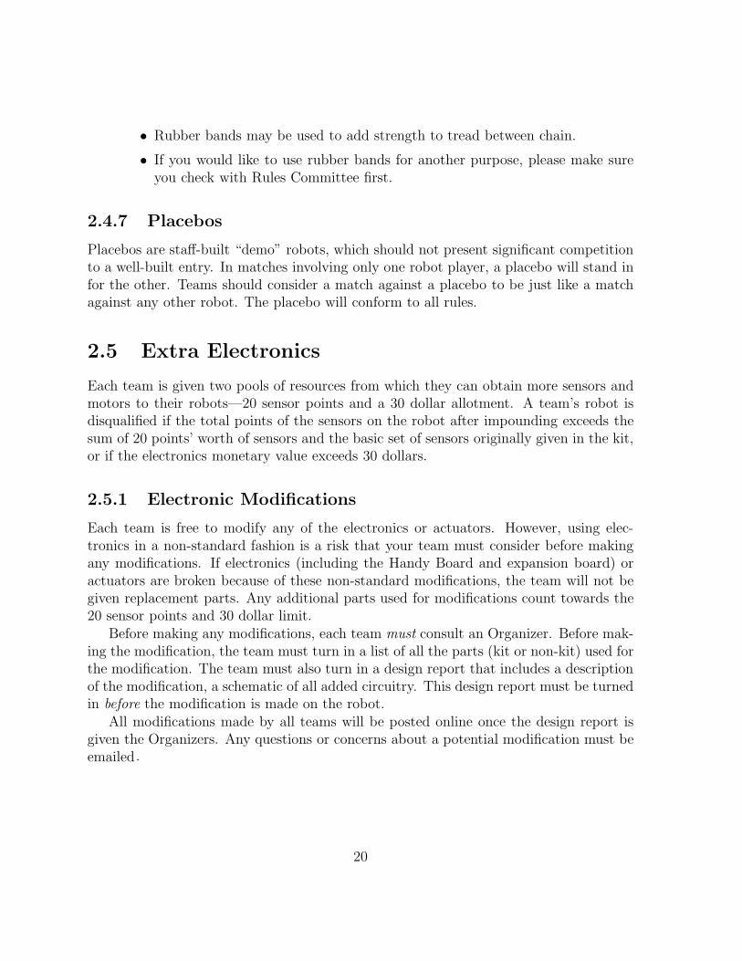
• Rubber bands may be used to add strength to tread between chain.
• If you would like to use rubber bands for another purpose, please make sure you check with Rules Committee first.
2.4.7 Placebos
Placebos are staff-built “demo” robots, which should not present significant competition to a well-built entry. In matches involving only one robot player, a placebo will stand in for the other. Teams should consider a match against a placebo to be just like a match against any other robot. The placebo will conform to all rules.
2.5 Extra Electronics
Each team is given two pools of resources from which they can obtain more sensors and motors to their robots—20 sensor points and a 30 dollar allotment. A team’s robot is disqualified if the total points of the sensors on the robot after impounding exceeds the sum of 20 points’ worth of sensors and the basic set of sensors originally given in the kit, or if the electronics monetary value exceeds 30 dollars.
2.5.1 Electronic Modifications
Each team is free to modify any of the electronics or actuators. However, using electronics in a non-standard fashion is a risk that your team must consider before making any modifications. If electronics (including the Handy Board and expansion board) or actuators are broken because of these non-standard modifications, the team will not be given replacement parts. Any additional parts used for modifications count towards the 20 sensor points and 30 dollar limit.
Before making any modifications, each team must consult an Organizer. Before making the modification, the team must turn in a list of all the parts (kit or non-kit) used for the modification. The team must also turn in a design report that includes a description of the modification, a schematic of all added circuitry. This design report must be turned in before the modification is made on the robot.
All modifications made by all teams will be posted online once the design report is given the Organizers. Any questions or concerns about a potential modification must be emailed.
20

2.5.2 The Sensor Store
In order to encourage variety in robot designs, each team will be given a sample set of sensors and an allowance of 20 sensor points with which they may obtain additional sensors from the Organizers. No refunds will be permitted, so contestants are encouraged to experiment with the sample sensors before making decisions on which sensors to get. Note that sensors purchased from the sensor store are considered kit parts and must be used in accordance with all applicable rules.
Sensors can be traded as long as the following rules are observed:
1. Teams are allowed to trade sensors of equal point value with other teams.
2. A team can trade a sensor with the Sensor Store as long as the sensor is returned in original condition.
3. A broken sensor may be traded in for a new sensor of the same type at a cost of 5 dollars or the at-cost price of the sensor rounded up to the nearest dollar, whichever is highest. Paying for a broken sensor this way does not count to the 30 dollar nor the 20 sensor point allotment.
2.5.3 30 Dollar Electronics Rule
A team may spend up to 30 dollars of its own funds to purchase electronic components from non-6.270 sources. This is not to be confused with the sensor points, which can only be used for the Sensor Store. Contestants are encouraged to use this rule to explore new ways of sensing or otherwise make their robot more interesting. Teams taking advantage of this provision, however, must abide by the following guidelines:
1. Each team is required to submit receipts for every additional component purchased. All receipts must be submitted at impounding.
2. If a team wishes to use parts obtained through means other than retail purchase, an equivalent cost will be assigned by the Organizers. This estimate must be obtained in writing from the Organizers.
3. Resistors rated less than 1 watt and capacitors valued less than 100 µ F may be used freely, without counting towards the 30 dollar total.
4. Extra servos can be purchased from 6.270 staff at varying prices based on quality.
5. If a team needs a replacement servo, the team must pay for the servo at retail price rounded up to the nearest dollar. The replacement fee does not count towards the 30 dollar allotment.
21

6. Only components on the actual impounded robot will count towards the 30 dollar allotment.
22

Chapter 3
The Human Factor
Participating in a challenging activity can be either a rewarding or stressful experience. Whether it is the former or the latter, however, depends entirely on you. In 6.270, you will be faced with the challenge of building a functional robot in a short period of time, which is by no means an easy task. Accomplishing this will not only require technical expertise, but also the ability to motivate yourself and to contribute as a member of a team.
Since each person is different and has his own unique set of skills to offer, there is no one correct way to approach the course. This chapter, therefore, is meant to present some suggestions for dealing with the human aspects of the course. Whether you take this advice or develop your own approach is entirely up to you.
3.1 Survival Tips
When working on a large project, many human factors come into play. In order to effectively contribute, you must not only have the knowledge, but also the desire and ability to apply it. Remaining motivated for the duration of the task can be difficult, and participants often find themselves feeling burnt out and stressed. This stress results in fatigue, irritability, and poor performance which in turn leads to more problems and more stress. If you keep the following tips in mind, however, you will be able to minimize your stress and stay motivated:
• Have fun. The best way to remain motivated is to simply enjoy the experience and have fun. Beware of falling into the trap of thinking that your robot has to be the best. This course is not about winning or scoring a lot of points; It is about having fun and learning something in the process. If you simply keep a positive
23

attitude and take the time to enjoy the course, you will find it to be a very rewarding experience.
• Take care of yourself. While skipping a few meals or pulling an all-nighter might seem like a good way to get some extra work done, in the long run, it tends to be counterproductive. Neglecting your body’s needs will inevitably leave you tired and drained, making you much less productive and increasing your chances of catching an illness. If you eat and sleep on a regular schedule, you will find that you are healtier and more motivated.
• Start early. Building a robot takes longer than you expect, even when you take that fact into account. By starting early and following a reasonable schedule, you will allow yourself the time to get things done without the stress of working at the last minute. If you plan well, you can spend the last few days goofing around with your robot and making those little last minute adjustments instead of pulling all-nighters just trying to make the robot work.
• Share your ideas. Many people think that by keeping the design of their robot a secret they will gain a competitive advantage; however, this is usually not the case. When you are willing to share your ideas with others, others will be willing to share their ideas with you. Quite often, another team will be able to suggest an idea that you have missed or a solution that you have been unable to find.
• Take a break. If you find yourself arguing with your teammates or becoming frustrated over a problem, take a break and do something else. Getting away from the robot and your teammates for awhile will help you relax and allow you to collect your thoughts. The world has many experiences to offer and exploring some of them might be just what you need.
3.2 Teamwork
One of the most essential parts of any large project is teamwork. A person working alone will not have the time to learn and do everything necesssary to accomplish the task. A team, on the other hand, can draw upon the talents and manpower of all of its members, making it much more productive than an individual.
3.2.1 Planning
Before a team begins work on a problem, it has to develop a plan. Rushing ahead is likely to cause work to be duplicated or important tasks to be missed. Worse still, failure
24

to plan ahead can lead to incompatibilities in parts that are supposed to fit together. When discovered too late, these errors can prove fatal to the project.
A good place to begin planning is to decide what the team is interested in accomplishing. Some teams are focused on winning while others just want to have a little fun. Still others are interested in the learning process and would prefer to spend more time on the parts that are most educational. It does not matter what goals a team sets for itself as long as all the members understand and agree with the overall vision. This will help coordinate the efforts of all the team members and provide direction for the project.
3.2.2 Brainstorming
Teams often employ the technique of brainstorming for generating potential solutions to a problem. During such a session, participants think alound, suggesting ideas as quickly as they can think of them. Other members of the team can then use those thoughts to create new ideas of their own which they throw back to the group. When it works well, a team can combine the knowledge and creativity of all its members to generate solutions that an individual would not even consider. The following guidelines will help make a brainstorming session as effective as possible:
1. No squashing. Negative comments have no place in brainstorming. Insulting another person’s ideas will cause them to be reluctant to offer further suggestions.
2. Don’t hold back. The process only works if everyone shares their thoughts. Even the silliest idea can often inspire a great one.
3. Stay on topic. During the course of discussion, it is easy to wander off on a tangent. Focus on the problem at hand and avoid distractions.
4. Relax. Ideas flow more freely in a relaxed environment. Find a quiet, comfortable place where the team can concentrate on the task at hand.
3.2.3 Constructive Conflict
Teams composed of members who always agree with each other work quickly and efficiently but never produce the best solution. Instead, the teammates who disagree often are the ones that build the strongest teams. This may seem counterintuitive at first, but it turns out that conflict, if handled correctly, can be one of a team’s greatest strengths.
Shouting at each other and throwing tantrums will certainly not accomplish anything, but calm, rational debate allows the team to view a topic from multiple perspectives. This not only allows the team to consider various possible solutions, but it also forces the issue to be examined in greater depth. Often, you will find that an idea that seems
25
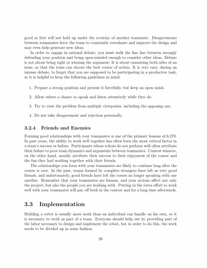
good at first will not hold up under the scrutiny of another teammate. Disagreements between teammates force the team to constantly reevaluate and improve the design and may even help generate new ideas.
In order to engage in rational debate, you must walk the fine line between strongly defending your position and being open-minded enough to consider other ideas. Debate is not about being right or winning the argument; It is about examining both sides of an issue, so that the team can choose the best course of action. It is very easy, during an intense debate, to forget that you are supposed to be participating in a productive task, so it is helpful to keep the following guidelines in mind:
1. Prepare a strong position and present it forcefully, but keep an open mind.
2. Allow others a chance to speak and listen attentively while they do.
3. Try to view the problem from multiple viewpoints, including the opposing one.
4. Do not take disagreement and rejection personally.
3.2.4 Friends and Enemies
Forming good relationships with your teammates is one of the primary lessons of 6.270. In past years, the ability to work well together has often been the most critical factor in a team’s success or failure. Participants whose robots do not perform well often attribute their failure to poor team dynamics and arguments between teammates. Contest winners, on the other hand, usually attribute their success to their enjoyment of the course and the fun they had working together with their friends.
The relationships you form with your teammates are likely to continue long after the course is over. In the past, teams formed by complete strangers have left as very good friends, and unfortunately, good friends have left the course no longer speaking with one another. Remember that your teammates are human, and your actions affect not only the project, but also the people you are working with. Putting in the extra effort to work well with your teammates will pay off both in the contest and for a long time afterwards.
3.3 Implementation
Building a robot is usually more work than an individual can handle on his own, so it is necessary to work as part of a team. Everyone should help out by providing part of the labor necessary to design and implement the robot, but in order to do this, the work needs to be divided up in some fashion.
26

3.3.1 Division of Labor
Each person brings a different set of strengths to the team, so many teams opt to divide the work into a number of subtasks, each of which becomes the responsibility of an individual team member. In this specialist approach, each person works on one area of the project and becomes an expert at it. The most common division in 6.270 is into hardware, software, and LEGO construction, but as long as the work is divided along clearly defined abstraction barriers, the communication needed to organize the team is small. This tends to be very efficient, especially for teams whose members come into the course with varying backgrounds and interests, though it tends to lead to a very narrow learning experience for the individual.
Another popular division of labor is the generalist approach, where every member of the team shares equally in all aspects of the implementation. This allows each individual to have a say in every part of the design and to gain an overall understanding of the process. It also requires that the teammates work in close proximity which can lead to a more fun and relaxed experience. Because of the amount of coordination needed between teammates, though, a great deal of time will have to be spent on organization and communication. This makes the implemenation less efficient, but can often lead to a better learning experience.
3.3.2 Debugging
Debugging can be a long and tedious process, so it is important to follow good design practice to minimize the number of bugs you will have to fix. Regardless of how careful you are, though, mistakes are inevitable and debugging will be necessary. As a general rule, it will take longer than you think to debug, so it is always better to allocate too much time for debugging than too little.
Occasionally, you will run into a bug that just seems to elude you. In these cases, instead of banging your head on the wall, you should. Have a teammate review your work and search for the bug. It may be that you are using a bad assumption or that you are continually missing the same mistake. When this happens, a teammate can bring a fresh perspective to the problem which might yield the answer.
Some teams take this debugging philosophy even further. No person on the team ever debugs his own work. Instead, each person gives their work to another teammate and that person debugs it. This way, each part of the project benefits from the input of at least two people.
27

3.4 Contest Tips
Everything always goes wrong at the worst possible time, which in 6.270, is contest night. There is nothing more heartbreaking than having your robot not work because of some small oversight. To help minimize the chances of such unfortunate occurrences, follow the tips below when preparing for the competition:
1. When making practice runs with your robot, try to avoid helping it. During actual competition, you will not be able to touch your robot when it does something wrong.
2. Practice your calibration routine in lab, so you can do it quickly and accurately at the contest. You must be able to complete your routine within a fixed time limit.
3. The lighting conditions at the contest will be different from those in the lab. Make sure that your light sensors are well-shielded and can be calibrated to work under different conditions.
4. Be aware of how your proximity will affect the calibration of your robot. When you lean over your robot, you can cast shadows or cause reflections which could affect the measurements of your sensors.
5. Develop a checklist for preparing your robot to compete. Between rounds you should examine your robot and repair anything that has broken.
6. Bring a repair kit to the contest. This should include a fresh set of batteries and a replacement for any part that tends to wear down or break during operation.
7. Have fun.
28
Chapter 4
Electronic Assembly
This chapter presents an introduction to electronic assembly followed by step-by-step instructions for assembling the hardware used in 6.270. The instructions assume no prior background in electronics and should provide enough information to get you started. It is recommended that you assemble the components in the order presented by this chapter. The sections are arranged to give you a gentle introduction before you go on to tackle the tougher tasks.
If ever there was a place in life where neatness counts, it is in electronic assembly. A neatly built and carefully soldered circuit will perform well for years. A sloppily and hastily assembled circuit, however, will cause ongoing problems and failures at inopportune times. It is well worth the extra effort to make sure you get it right the first time.
4.1 Soldering
Soldering is a method of creating electrically conductive connections between electronic components. A special type of metal, called solder, is melted onto the joint and allowed to harden. This forms a bond between the components which joins them both structurally and electrically. A soldering iron is extremely valuable for constructing electronic circuits, but as with any tool, you must begin by mastering the skills necessary to use it.
Aside from the sensors and actuators, your team will be required to solder the RF board, the expansion board for the Handy Board, and the battery recharger for the expansion board. It is crucial that you solder the circuitry cleanly and correctly.
29
4.1.1 Safety
Soldering is not a dangerous activity, but if you do not respect the soldering iron, it can does have the potential to cause harm. While you work, it is important to observe the following safety rules:
1. Keep the soldering iron tip away from everything except the point to be soldered. The iron is hot and can easily damage parts, cause burns, or even start a fire.
2. Keep the soldering iron in its holder when not in use. Never wave the soldering iron around or hand it to another person. If someone else wants the iron, place it in its stand and let him pick it up from there.
3. Never assume that a soldering iron is cold. Always check the iron before you pick it up.
4. Do not touch a joint immediately after soldering it. It takes a moment for the solder to cool back down.
4.1.2 Technique
Before you begin any work with the soldering iron, you should assemble all of the tools that you will be using. The ones that you will require include a soldering iron, stand, solder, and a damp sponge. You may also wish to have a set of helping hands, cutters, and wire strippers available if needed for the task.
Once you heat up the iron, the first thing to do is tin it. Wipe the tip on a damp sponge to clean it and then immediately melt some fresh solder onto it. This gives the tip a protective coating and also helps improve heat transfer. You should tin the tip again each time you use the iron or when it has been sitting idle for awhile. A properly tinned iron should have a shiny silver tip, so if it ever becomes dull or dirty, it needs to be tinned again.
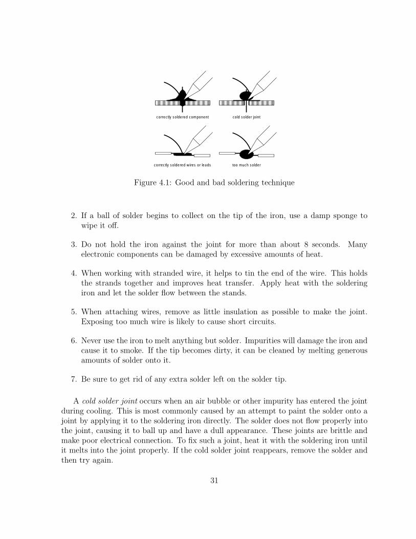
With a properly tinned iron, you are ready to solder. Firmly secure the parts to be soldered with a set of helping hands. Heat the two surfaces by inserting the tip of the iron into the point where they touch each other. The solder should be applied to the joint, not to the iron directly. This way, the solder is melted by the joint, and both metal surfaces are heated to the temperature necessary to bond chemically with the solder. When done properly, the solder will be drawn into the joint to fill the connection. Figure 4.1 shows the results of good and bad soldering technique. The following pointers can be useful in honing your skills:
1. If the solder does not melt easily into the joint, applying a small amount of extra solder to the iron will improve heat transfer.
30
correctly soldered component cold solder joint
correctly soldered wires or leads too much solder
Figure 4.1: Good and bad soldering technique
2. If a ball of solder begins to collect on the tip of the iron, use a damp sponge to wipe it off.
3. Do not hold the iron against the joint for more than about 8 seconds. Many electronic components can be damaged by excessive amounts of heat.
4. When working with stranded wire, it helps to tin the end of the wire. This holds the strands together and improves heat transfer. Apply heat with the soldering iron and let the solder flow between the stands.
5. When attaching wires, remove as little insulation as possible to make the joint. Exposing too much wire is likely to cause short circuits.
6. Never use the iron to melt anything but solder. Impurities will damage the iron and cause it to smoke. If the tip becomes dirty, it can be cleaned by melting generous amounts of solder onto it.
7. Be sure to get rid of any extra solder left on the solder tip.
A cold solder joint occurs when an air bubble or other impurity has entered the joint during cooling. This is most commonly caused by an attempt to paint the solder onto a joint by applying it to the soldering iron directly. The solder does not flow properly into the joint, causing it to ball up and have a dull appearance. These joints are brittle and make poor electrical connection. To fix such a joint, heat it with the soldering iron until it melts into the joint properly. If the cold solder joint reappears, remove the solder and then try again.
31
4.1.3 Mounting Components
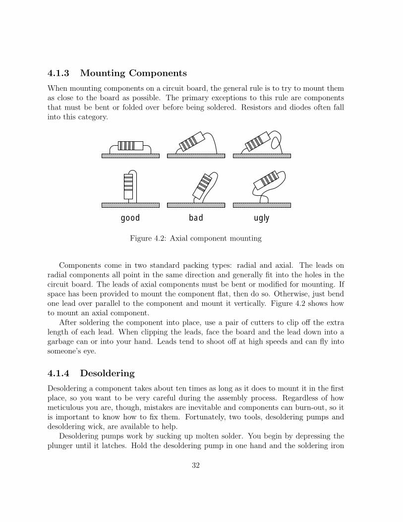
When mounting components on a circuit board, the general rule is to try to mount them as close to the board as possible. The primary exceptions to this rule are components that must be bent or folded over before being soldered. Resistors and diodes often fall into this category.
good bad ugly
Figure 4.2: Axial component mounting
Components come in two standard packing types: radial and axial. The leads on radial components all point in the same direction and generally fit into the holes in the circuit board. The leads of axial components must be bent or modified for mounting. If space has been provided to mount the component flat, then do so. Otherwise, just bend one lead over parallel to the component and mount it vertically. Figure 4.2 shows how to mount an axial component.
After soldering the component into place, use a pair of cutters to clip off the extra length of each lead. When clipping the leads, face the board and the lead down into a garbage can or into your hand. Leads tend to shoot off at high speeds and can fly into someone’s eye.
4.1.4 Desoldering
Desoldering a component takes about ten times as long as it does to mount it in the first place, so you want to be very careful during the assembly process. Regardless of how meticulous you are, though, mistakes are inevitable and components can burn-out, so it is important to know how to fix them. Fortunately, two tools, desoldering pumps and desoldering wick, are available to help.
Desoldering pumps work by sucking up molten solder. You begin by depressing the plunger until it latches. Hold the desoldering pump in one hand and the soldering iron
32

in the other. Use the soldering iron to melt the solder and then quickly remove the iron as you bring in the pump. Immediately trigger the pump to suck up the solder before it resolidifies. The next time the plunger is depressed, the collected solder will be ejected from the pump. The tip of the desoldering pump is made of Teflon so that solder cannot stick to it. While Teflon is heat-resistant, it is not invincible, so be careful not to touch the Teflon tip directly to the soldering iron.
Another option for removing solder is to use desoldering wick. The wick is composed of a number of small braided wires and is used in conjunction with the soldering iron to pick up solder. You simply melt the solder with the iron and touch the wick to it. Solder has a strong attraction to the wick, so the molten solder will flow into the braid. This allows you to collect the solder, but once the solder wick is used, that part of it cannot be used again.
4.2 Components
Electronic circuits are constructed from a number of different types of building blocks. These components come in all different shapes and sizes and have a variety of functions. Building them into a working circuit requires being able to identify their packages and read their values.
Some components are also polarized. They must be mounted in the correct orientation otherwise they will not function correctly and might even explode. Being able to reliably read the markings which identify the polarity of a device can save hours of frustration.
4.2.1 Resistors
Resistors are usually small cylindrical devices with color-coded bands indicating their value. Most of the resistors that you will use are 1/8 watt, which is a very low power rating, thus they are rather tiny devices. Resistors with higher power ratings tend to be much larger. A 2 watt resistor is a large cylinder, while a 5 watt resistor has a large rectangular package. Regardless of size, all resistors are nonpolarized, so they may be installed in either direction without causing problems.
The largest resistors often have their value printed on them, but all other resistors are labelled using a standard color code. The code consists of four colored bands around the resistor package. The first two bands form the mantissa, and the third is the exponent. The resistance is read by taking the number formed by the mantissa values and multiplying it by ten raised to the power of the exponent. The fourth band represents the tolerance of the resistor. It can be either silver for 10% tolerance or gold for 5% tolerance. If the fourth band is missing, then the tolerance is 20%.
33

color black brown red
orange yellow green blue violet gray white
mantissa multiplier value value
0 1 1 10 2 100 3 1,000 4 10,000 5 100,000 6 1,000,000 7 8 9
Figure 4.3: Resistor color code
Figure 4.3 shows the meaning of the colors. A few examples should demonstrate how to read a resistor:
• brown, black, red: 1,000Ω or 1kΩ
• yellow, violet, orange: 47,000Ω or 47kΩ
• red, red, yellow: 220,000Ω or 220kΩ
4.2.2 Resistor Packs
Resistor packs are a collection of resistors in a flat, rectangular package. The two basic types of resistor packs are shown in Figure 4.4:
• Isolated Element resistor packs contain three to five discrete resistors. The pack is labelled with a “V” in front of the resistance value, such as “V47kΩ .” These devices are not polarized and can be installed in either direction.
• Common Terminal resistor packs contain anywhere from three to nine resistors per package with each resistor connected to the common terminal. The pack is labelled with an “E” in front of the resistance value, such as “E47kΩ .” These devices are polarized and are marked with either a dot or bar at the end of the package with the common pin.
34

Isolated Element Common Terminal
Figure 4.4: Resistor pack internal wiring
4.2.3 Capacitors
Capacitors are available in a variety of types and values:
• Monolithic capacitors are small components about the size and shape of the head of a match. They are excellent choices when small values (1.0µF or less) are needed because they are compact and inexpensive. They are never polarized.
• Electrolytic capacitors look like minature tin cans with a plastic wrapper. They are available in large values (1.0µF or greater), but become quite bulky as the value increases. They are fairly inexpensive, so they are a common choice for many applications. Except for a few special cases, electrolytics are usually polarized.
• Tantalum capacitors are compact, bulb-shaped components. They are excellent for larger values (1.0µF or greater), since they are smaller and more reliable than electrolytic. Unfortunately, though, they are also much more expensive. They are always polarized.
Polarized capacitors have a tendency to explode when they are mounted backwards, so it is important to know how to read them correctly. Some of them are easy and have one or both of the leads marked with a plus (+) or minus (-). Others have the positive lead marked with either a dot or a vertical bar. This should not be confused with the stripe with several minus signs on it which marks the negative lead on some electrolytics.
Reading capacitor values can be even more confusing than determining their polarity. Capacitors often have numbers printed on the package which have nothing to do with the value, so the first task is to figure out which are the relevant numbers.
For large capacitors (1.0µF or greater), the value is often printed plainly on the packages, such as 4.7µF. In some cases, the µ symbol acts as a decimal point like 4µ 7 for a 4.7µF value. Small capacitors (1.0µF or less) have their values printed in picofarads (1, 000, 000pF = 1µF). These values are coded in a manner similar to resistor values
35
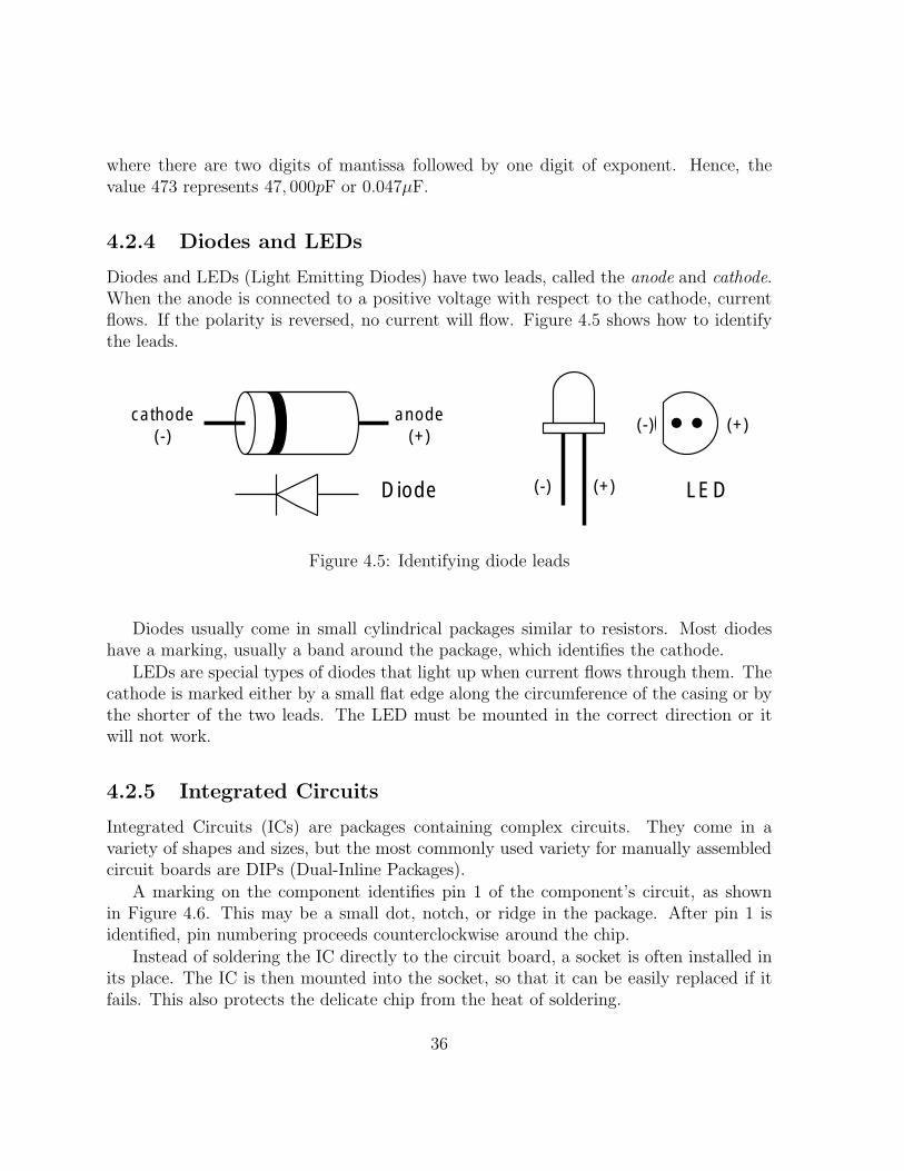
where there are two digits of mantissa followed by one digit of exponent. Hence, the value 473 represents 47, 000pF or 0.047µF.
4.2.4 Diodes and LEDs
Diodes and LEDs (Light Emitting Diodes) have two leads, called the anode and cathode. When the anode is connected to a positive voltage with respect to the cathode, current flows. If the polarity is reversed, no current will flow. Figure 4.5 shows how to identify the leads.
cathode anode (-) (+)(-) (+)
(-) (+)Diode LED
Figure 4.5: Identifying diode leads
Diodes usually come in small cylindrical packages similar to resistors. Most diodes have a marking, usually a band around the package, which identifies the cathode.
LEDs are special types of diodes that light up when current flows through them. The cathode is marked either by a small flat edge along the circumference of the casing or by the shorter of the two leads. The LED must be mounted in the correct direction or it will not work.
4.2.5 Integrated Circuits
Integrated Circuits (ICs) are packages containing complex circuits. They come in a variety of shapes and sizes, but the most commonly used variety for manually assembled circuit boards are DIPs (Dual-Inline Packages).
A marking on the component identifies pin 1 of the component’s circuit, as shown in Figure 4.6. This may be a small dot, notch, or ridge in the package. After pin 1 is identified, pin numbering proceeds counterclockwise around the chip.
Instead of soldering the IC directly to the circuit board, a socket is often installed in its place. The IC is then mounted into the socket, so that it can be easily replaced if it fails. This also protects the delicate chip from the heat of soldering.
36

14 13 12 11 10 9 8
1 2 3 4 5 6 7
notch
Figure 4.6: Top view of a 14-pin DIP
Sockets are not polarized, but they often carry a marking similar to the chips that they will be holding. Installing the socket with the notch in the proper orientation will make it easier to install the IC correctly.
4.3 Connectors
Sensors and actuators must be connected to the controller board using wires. Since it is desirable to be able to plug and unplug them, connectors are used which fit into the various ports. This provides a simple, modular design.
Sensors Motors
Vcc
signal
GND
Vcc connected only on powered sensors
GND
output
Beacon
GND (-)
Vcc (+)
output
Figure 4.7: 6.270 connector standard
In order to keep connectors from being plugged into the wrong port, different types of components are built with different connectors. Figure 4.7 shows the configuration
37

used for each device. When building connectors for polarized devices, it is important to attach the wires to the pins in the correct order.
1. Cut a length of ribbon cable with the appropriate number of wires for the device you are building. “Unzip” the ribbon cable by separating the individual wires.
2. Strip and tin both ends of the wires. Remove just enough insulation from the ends of the wires to allow them to be soldered.
3. With your fingers, twist the threads of each individual wire end tightly.
′′ ′′4. Slip each wire through a 1
4length of 1
16 heat shrink.
5. Cut a connector with the necessary number of pins from a piece of male header. Clip out any unneeded pins with a pair of cutters.
6. Solder the wires to the connector.
7. Slip the heat shrink over the soldered wire and connector. Use a heat gun to shrink the wrap tightly over the connection. A match or butane lighter may be used if a heat gun is unavailable, but beware of burning the insulation. Hold the joint so the heat shrink tubing is about 1′′ above the tip of the flame.
8. If heat shrink is unavailable, hot glue may instead be used to strengthen and insulate the connection.
(a) Apply the glue to fill the void between the wires.
(b) While the glue is still hot, use a pair of pliers to flatten it. The pliers will also work as a heatsink to cool the glue faster.
(c) After ten seconds, carefully peel the connector from the pliers being careful not to break it. Trim off any excess glue.
4.4 Motors
The DC motors used in 6.270 are great for building robots because they are compact and powerful. Unfortunately, though they are not designed to be used with LEGO parts. To make them compatible with your robot, you will have to legoize them.
1. Mount a LEGO gear on the motor shaft
38

(a) If the motor comes with a metal gear on its shaft, remove it with a pair of wire strippers. Place the jaws of the strippers between the motor and gear and squeeze. When the strippers close, the bevel in the cutters should pry the gear off.
′′(b) Shrink a piece of 1
16 heat-shrink tubing onto the motor’s shaft. Then shrink
′′two additional 1
8pieces around that. An 8-tooth LEGO gear should now fit
snugly over the tubing.
(c) Push an 8-tooth gear over the head-shrink tubing. Make sure that it goes all the way on and that it is aligned correctly.
(d) Cut off any excess tubing which sticks out from the end of the gear.
2. Legoize the motor
(a) Construct the jig shown in Figure 4.8. It requires 4 1 × 10 beams, 2 1 × 6 beams, 1 1 × 4 beam, 2 1 × 2 beams, 1 2 × 2 brick, 4 2 × 4 plates, 10 black connectors, 2 axle connectors, 1 40-tooth gear, and 1 24-tooth gear. If you are left-handed, you might find it more useful to construct the mirror image of the jig.
1x6
1x6 beam
2x2 brick 1x2 beam
1x2 beam
2x4 plate
2x4 plate
2x4 plate
2x4 plate 2x4 plate
2x4 plate
2x4 plate
2x4 plate
1x10 beam
1x10 beam
1x10 beams
beams
1x4 beam 1x4
place 40-tooth gear here
place 24-tooth gear here
mount 1 mount 2
1x10 beams
1x10 beams
1x2 beam
1x10 beams
open this way
pegs
beam
left front right
Figure 4.8: Jig for motor assembly
(b) Open the jig by disconnecting the top beams at the left side and flipping the top to the right.
(c) Attach a piece of double-sided foam tape to the top of a 2× 4 plate. This will become the bottom of the legoized motor. Mount this into the bottom of the jig, at the spot marked, “mount 1.”
39
(d) Attach the motor to the 2×4 LEGO plate prepared in the previous step. Make sure that the gear on the motor’s shaft lines up correctly with the 40-tooth gear on the jig.
(e) Attach a piece of double-sided foam tape to the bottom of another 2× 4 plate. This will become the top of the legoized motor. Mount this onto the top of the jig which you earlier flipped open, so that it will align with the top of the motor.
(f) Close the top of the jig to press the top onto the motor. Carefully remove the completed motor from the jig.
(g) You should then place the motor at “mount 2” to test that it meshes correctly with the 24-tooth gear. If it does not, you will need to figure out what went wrong.
Note: If you are building a non-standard 6.270 motor, you can use “mount 2” to determine the proper vertical spacing and revise the instructions above appropriately.
3. Wire a connector to the motor
(a) Cut a length of ribbon cable with two strands of wire.
(b) On the side of the motor are two metal leads or pads. Solder one wire to each.
(c) Solder the other end of the wire to a connector appropriate for a motor.
(d) Glue the wire to the case of the motor using hot glue. This will provide stress relief to protect the solder joints.
4.5 Servo
A servo is an electric motor with an internal gear train, position sensor, and driver circuitry which allows the motor to be positioned with reasonable precision based upon the input signal. It can be moved to any orientation in an approximately 180 degree range.
Fortunately, the servo already has the appropriate female header needed to connect it to the expansion board for the Handy Board. Because the servo is polarized, be extremely
careful when attaching the servo to the expansion board. Make sure the black wire goes to ground (marked as “-” on the expansion board) and not to signal (marked “s”).
40

4.6 The Handy Board and Expansion Board
The “brain” of your robot is Fred Martin’s Handy Board, a controller based on the Motorola 68HC11 processor. This year, Fred has designed a modified version of the Handy Board’s expansion board, which makes it well-suited for use with 6.270. Features of the system (Handy Board + 6.270 Expansion Board) include the following:
1. A dual rechargable battery system—on-board NiCd batteries preserve program memory, off-board Hawker Cells power actuators.
2. Twenty-one analog inputs and nine digital inputs.
3. Three digital outputs.
4. Six bi-directional motor ports, four with speed control.
5. Six servo ports.
6. An LCD screen for debugging output.
All wiring diagrams found in these course notes should be compatible with the inputs and outputs of the HandyBoard. More information on the features and usage of the Handy Board can be found in The Handy Board Technical Reference, included with your course notes. If you have further questions, please talk to a member of the staff!
The controller can be programmed using Interactive C (IC), a language designed specifically for use in robotics. IC programs are compiled into pseudo-machine instructions (pcode), which are interpreted by a pcode interpreter installed on the Handy Board. For information on IC, see the The Interactive C Manual For the Handy Board, included with your course notes.
Instructions for assembling the expansion board are in Appendix B.
4.7 Batteries
The original Handyboard contained rechargable batteries that ran both the motors and the board logic. Consequently, the batteries drained fairly quickly. In 6.270, the expansion board contains a female connector
41

Chapter 5
Sensors
The concept of a sensor should already be familiar to you. You have an array of sensors which you use to feel, see, hear, taste, and smell. You rely on these senses for just about everything you do. Without them, you would be incapable of performing even the most simple tasks.
Robots are no different. Without sensors, they are merely machines, incapable of adapting to any change in the environment. Sensors give your robot the ability to collect information about the world around it and to choose an action appropriate to the situation.
After reading this chapter, you should take some time to play with your sensors. Wire at least one of each type and learn how it works, what values it returns, and under what conditions it will production those values. Every sensor has its own little quirks, and only through experimentation will you acquire the expertise necessary to integrate them into your robot.
5.1 Digital Sensors
Digital sensors work a lot like light switches. The switch can either be in the “on” position or the “off” position, but never in between. Even if you hold it in the center, the light will be either on or off. When a digital sensor is on, it returns a voltage which the controller interprets as a value of one. When it is off, the value is zero.
All digital sensors can be modelled as if they were switches. When plugged into a sensor port, digital sensors resemble one of the circuits shown in figure 5.1. When the switch is closed, electrical current flows freely through it, and the output is pulled down to GND. When the switch is open, the pullup resistor causes the signal line to float to Vcc. While Vcc usually represents a logic one, the value is inverted in software so that the value one represents the situation where the sensor is activated.
43
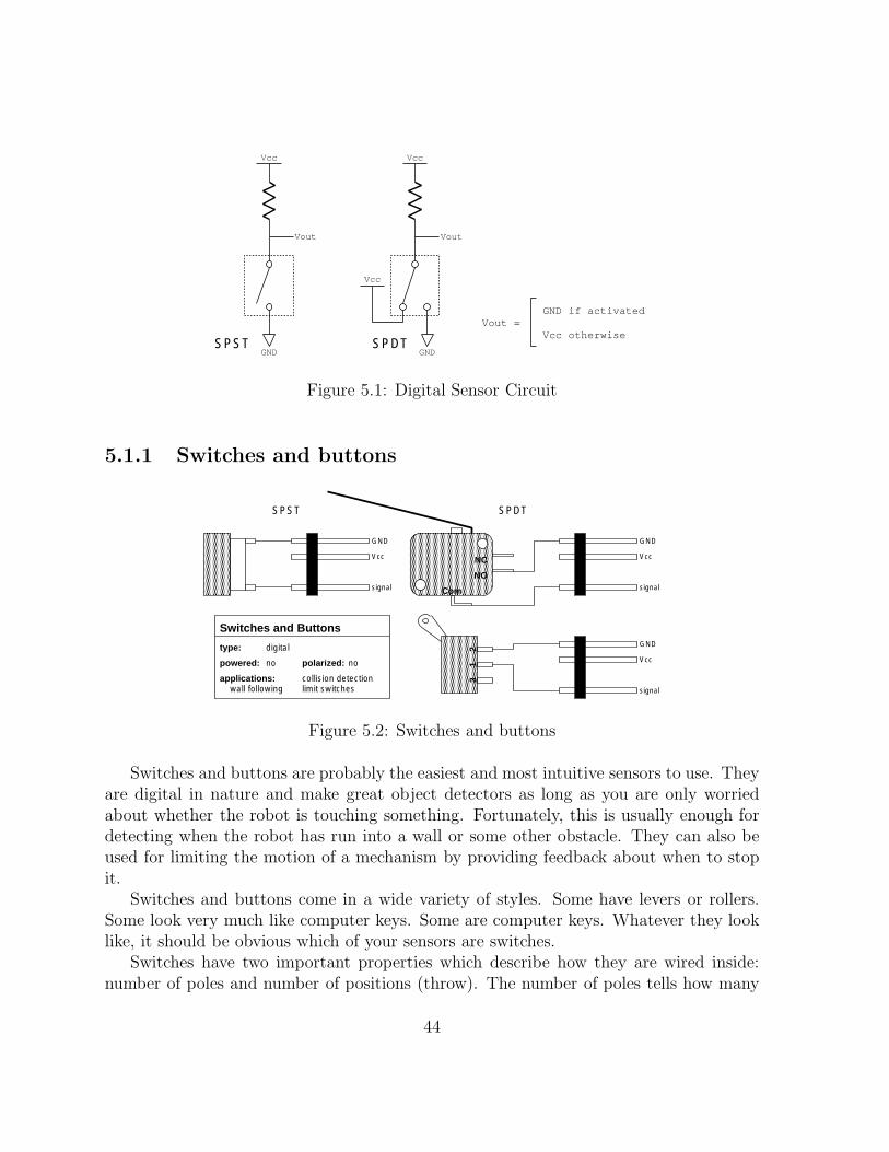
Vcc Vcc
Vout
Vcc
SPDT
Vout
Vout =
SPST GND GND
GND if activated
Vcc otherwise
Figure 5.1: Digital Sensor Circuit
5.1.1 Switches and buttons
NC
NO
Com
21
3
SPST SPDT
Switches and Buttons
type:
powered: polarized:no no
digital
applications: collision detection limit switcheswall following
GND
Vcc
signal
GND
Vcc
signal
GND
Vcc
signal
Figure 5.2: Switches and buttons
Switches and buttons are probably the easiest and most intuitive sensors to use. They are digital in nature and make great object detectors as long as you are only worried about whether the robot is touching something. Fortunately, this is usually enough for detecting when the robot has run into a wall or some other obstacle. They can also be used for limiting the motion of a mechanism by providing feedback about when to stop it.
Switches and buttons come in a wide variety of styles. Some have levers or rollers. Some look very much like computer keys. Some are computer keys. Whatever they look like, it should be obvious which of your sensors are switches.
Switches have two important properties which describe how they are wired inside: number of poles and number of positions (throw). The number of poles tells how many
44
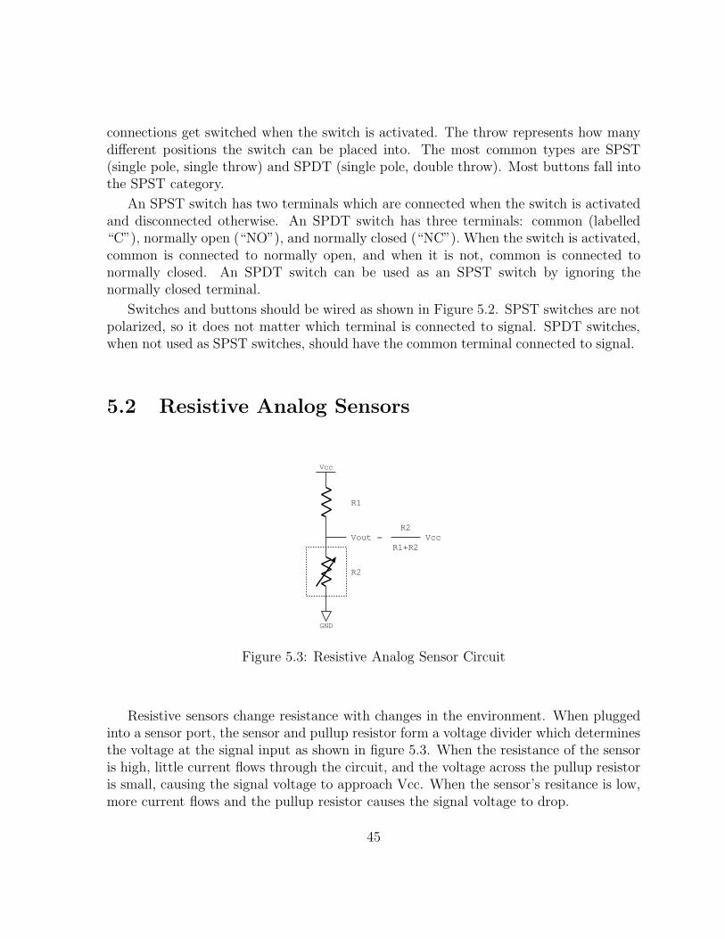
connections get switched when the switch is activated. The throw represents how many different positions the switch can be placed into. The most common types are SPST (single pole, single throw) and SPDT (single pole, double throw). Most buttons fall into the SPST category.
An SPST switch has two terminals which are connected when the switch is activated and disconnected otherwise. An SPDT switch has three terminals: common (labelled “C”), normally open (“NO”), and normally closed (“NC”). When the switch is activated, common is connected to normally open, and when it is not, common is connected to normally closed. An SPDT switch can be used as an SPST switch by ignoring the normally closed terminal.
Switches and buttons should be wired as shown in Figure 5.2. SPST switches are not polarized, so it does not matter which terminal is connected to signal. SPDT switches, when not used as SPST switches, should have the common terminal connected to signal.
5.2 Resistive Analog Sensors
Vcc
R1
R2
Vout =
GND
R2Vcc
R1+R2
Figure 5.3: Resistive Analog Sensor Circuit
Resistive sensors change resistance with changes in the environment. When plugged into a sensor port, the sensor and pullup resistor form a voltage divider which determines the voltage at the signal input as shown in figure 5.3. When the resistance of the sensor is high, little current flows through the circuit, and the voltage across the pullup resistor is small, causing the signal voltage to approach Vcc. When the sensor’s resitance is low, more current flows and the pullup resistor causes the signal voltage to drop.
45
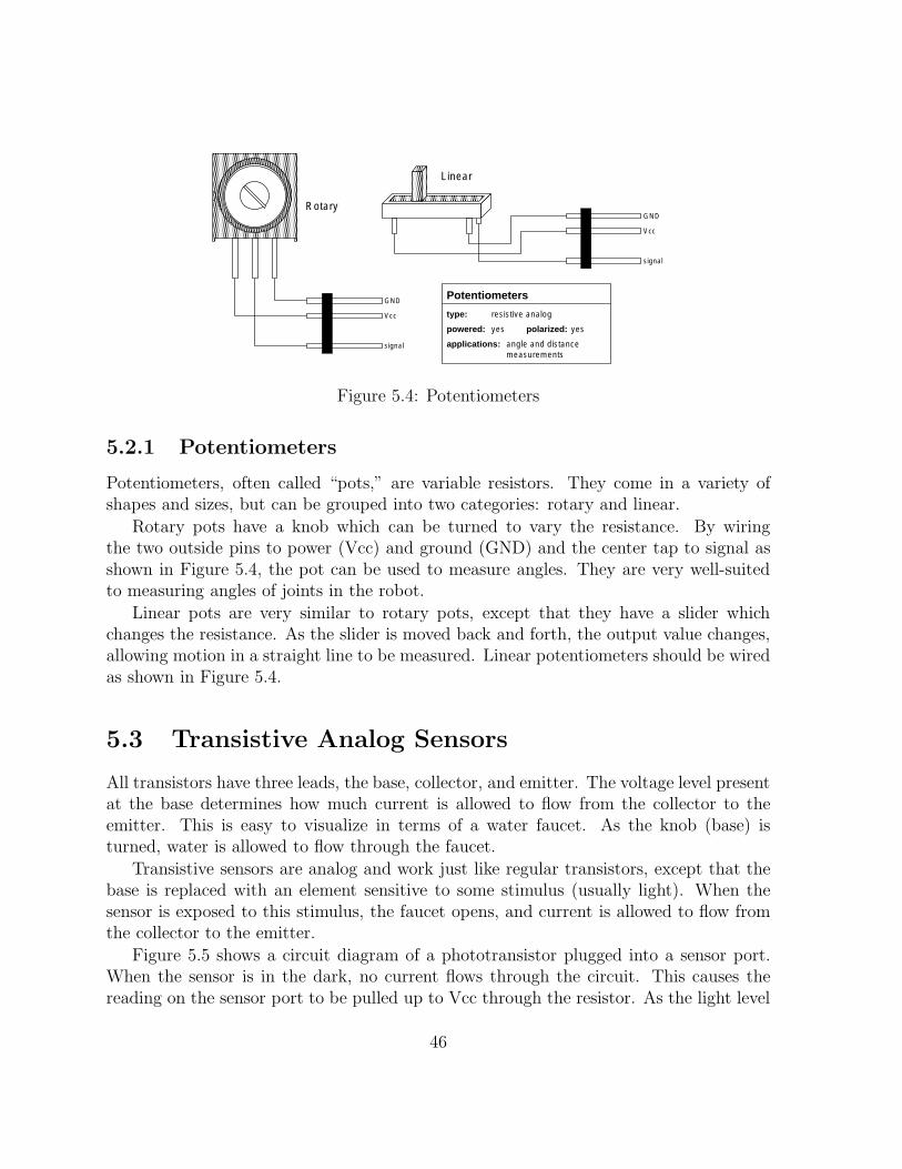
Potentiometers
type:
powered: polarized:yes yes
resistive analog
applications: angle and distance measurements
Linear
Rotary
GND
Vcc
signal
GND
Vcc
signal
Figure 5.4: Potentiometers
5.2.1 Potentiometers
Potentiometers, often called “pots,” are variable resistors. They come in a variety of shapes and sizes, but can be grouped into two categories: rotary and linear.
Rotary pots have a knob which can be turned to vary the resistance. By wiring the two outside pins to power (Vcc) and ground (GND) and the center tap to signal as shown in Figure 5.4, the pot can be used to measure angles. They are very well-suited to measuring angles of joints in the robot.
Linear pots are very similar to rotary pots, except that they have a slider which changes the resistance. As the slider is moved back and forth, the output value changes, allowing motion in a straight line to be measured. Linear potentiometers should be wired as shown in Figure 5.4.
5.3 Transistive Analog Sensors
All transistors have three leads, the base, collector, and emitter. The voltage level present at the base determines how much current is allowed to flow from the collector to the emitter. This is easy to visualize in terms of a water faucet. As the knob (base) is turned, water is allowed to flow through the faucet.
Transistive sensors are analog and work just like regular transistors, except that the base is replaced with an element sensitive to some stimulus (usually light). When the sensor is exposed to this stimulus, the faucet opens, and current is allowed to flow from the collector to the emitter.
Figure 5.5 shows a circuit diagram of a phototransistor plugged into a sensor port. When the sensor is in the dark, no current flows through the circuit. This causes the reading on the sensor port to be pulled up to Vcc through the resistor. As the light level
46
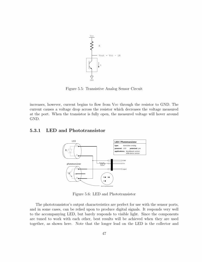
Vcc
GND
R
Vout = Vcc - iR
i
Figure 5.5: Transistive Analog Sensor Circuit
increases, however, current begins to flow from Vcc through the resistor to GND. The current causes a voltage drop across the resistor which decreases the voltage measured at the port. When the transistor is fully open, the measured voltage will hover around GND.
5.3.1 LED and Phototransistor
LED LED / Phototransistor
type: transistive analog
powered: LED polarized: yes
applications: breakbeam sensor reflectance sensor
C
B
E
C
E
phototransistor 330ohm
back of phototransistor
CB
E
GND
Vcc
signal
Figure 5.6: LED and Phototransistor
The phototransistor’s output characteristics are perfect for use with the sensor ports, and in some cases, can be relied upon to produce digital signals. It responds very well to the accompanying LED, but barely responds to visible light. Since the components are tuned to work with each other, best results will be achieved when they are used together, as shown here. Note that the longer lead on the LED is the collector and
47

should be connected with the 330Ω resistor to power. It also may be easier to solder the phototransistor if the base lead (“B”) is either bent or cut off.
Because the phototransistor is so sensitive, it is helpful to wrap some black heat shrink around it. This is especially useful when looking for light in a particular direction.
Once again, realize that the LED does not have to be perpetually on during the 60 seconds the robot competes. The LED can be plugged into a motor output to allow differential light measurements. And remember any number of LEDs can be plugged into a single motor port.
This sensor is particularly convenient when working with LEGO because it is just the right size to fit into the LEGO axle holes. It is very easy to mount this sensor into your robot when constructing breakbeam sensors and shaft encoders.
5.3.2 Breakbeam Sensor Package
D E
330ohm
Breakbeam Package
type: transistive analog / digital
powered: LED polarized: yes
applications: shaft encoding limit switches
GND
Vcc
signal
Figure 5.7: Breakbeam sensor package
The breakbeam sensor package is composed of an infrared LED and a phototransistor which is sensitive to the wavelength of light emitted by the LED. The two components are mounted in the package so that they face each other with a gap in between them.
The sensor should be wired as shown in Figure 5.7. As usual with LEDs, a 330Ω resistor will be needed to limit the amount of current used to light it. Be sure to orient the sensor correctly, so that you do not confuse the phototransistor half with the LED half. The markings vary from one package to the next, but usually include one or more of the following:
1. an “E” (emitter) for the LED and a “D” (detector) for the phototransistor marked above each component.
48
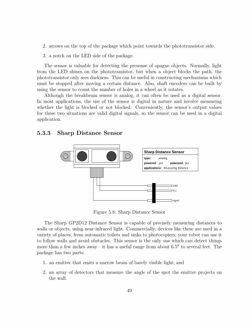
2. arrows on the top of the package which point towards the phototransistor side.
3. a notch on the LED side of the package.
The sensor is valuable for detecting the presense of opague objects. Normally, light from the LED shines on the phototransistor, but when a object blocks the path, the phototransistor only sees darkness. This can be useful in constructing mechanisms which must be stopped after moving a certain distance. Also, shaft encoders can be built by using the sensor to count the number of holes in a wheel as it rotates.
Although the breakbeam sensor is analog, it can often be used as a digital sensor. In most applications, the use of the sensor is digital in nature and involve measuring whether the light is blocked or not blocked. Conveniently, the sensor’s output values for these two situations are valid digital signals, so the sensor can be used in a digital application.
5.3.3 Sharp Distance Sensor
GND
Vcc
signal
Sharp Distance Sensor
type:
powered: polarized:yes yes
analog
applications: measuring distance
Figure 5.8: Sharp Distance Sensor
The Sharp GP2D12 Distance Sensor is capable of precisely measuring distances to walls or objects, using near-infrared light. Commercially, devices like these are used in a variety of places, from automatic toilets and sinks to photocopiers; your robot can use it to follow walls and avoid obstacles. This sensor is the only one which can detect things more than a few inches away—it has a useful range from about 6.5′′ to several feet. The package has two parts:
1. an emitter that emits a narrow beam of barely visible light; and
2. an array of detectors that measure the angle of the spot the emitter projects on the wall.
49

Unlike other devices used in 6.270, this device supplies an analog value on its own, without the use of a pull-up resistor. Therefore, to use the sensor, you must make a slight, reversible modification to the Handy Board—cut the trace on the bottom of the main board that connects an analog input to its pull-up resistor. Please see a member of the staff for help with this procedure.
The sensor does not give you the distance in any type of standard unit. Instead, the value read on the analog input it is connected to varies smoothly from 0 to 255 as the distance decreases. Tests have found that the function
950. ′′ ′′f [n] = −3.16 +
8.58 + n
gives an accurate estimate of the distance as a function of the analog value n, and that the reading is fairly independent of lighting, object color, or battery power level. However, the numeric parameters may have to be recalibrated for each individual sensor if an accurate measurement is desired.
5.4 Gyroscopes
From year to year we try out new sensors to improve the robots’ performance. For this year’s competition, Analog Devices is making available surface-micromachined
integrated circuit gyroscopes which can be used to measure your robot’s rate of turn or (with some numerical integration) angle of turn, which can be a signicant aid to navigation. These devices integrate the mechanical parts of the gyro along with the necessary circuitry on a single chip, so they are very small (about 7mm square). To make them easier to handle and use, the gyros are supplied on 1.25” square printed-circuit boards containing all necessary external components and a pin header for connections. A complete data sheet for the gyros (ADXRS300) can be found on the Analog Devices website, www.analog.com (select iMEMs Gyroscopes under the MEMs Technology category). However, most or all of what you need to know to use the gyros successfully in your robot will be presented here and in a lecture during the First week of the course.
A gyro measures rate of turn, and these gyros have a full-scale range of +/-300 degrees per second. They operate on a single 5V power supply, as supplied by the Handyboard’s I/O channels, and produce a single voltage output in the range of 0 to 5V, so they are wired and used like most other three-wire sensors (they are not, however, ratiometric to the power supply like accelerometers or potentiometers). The output of the gyro when it is not rotating is nominally 2.5V, midscale on the Handyboard’s A/D converter. The nominal sensitivity of the gyro is 5mV per degree per second of rotation. (Calibration routines may be used to take out the gyro’s offset and sensitivity errors at the beginning of a run.)
50
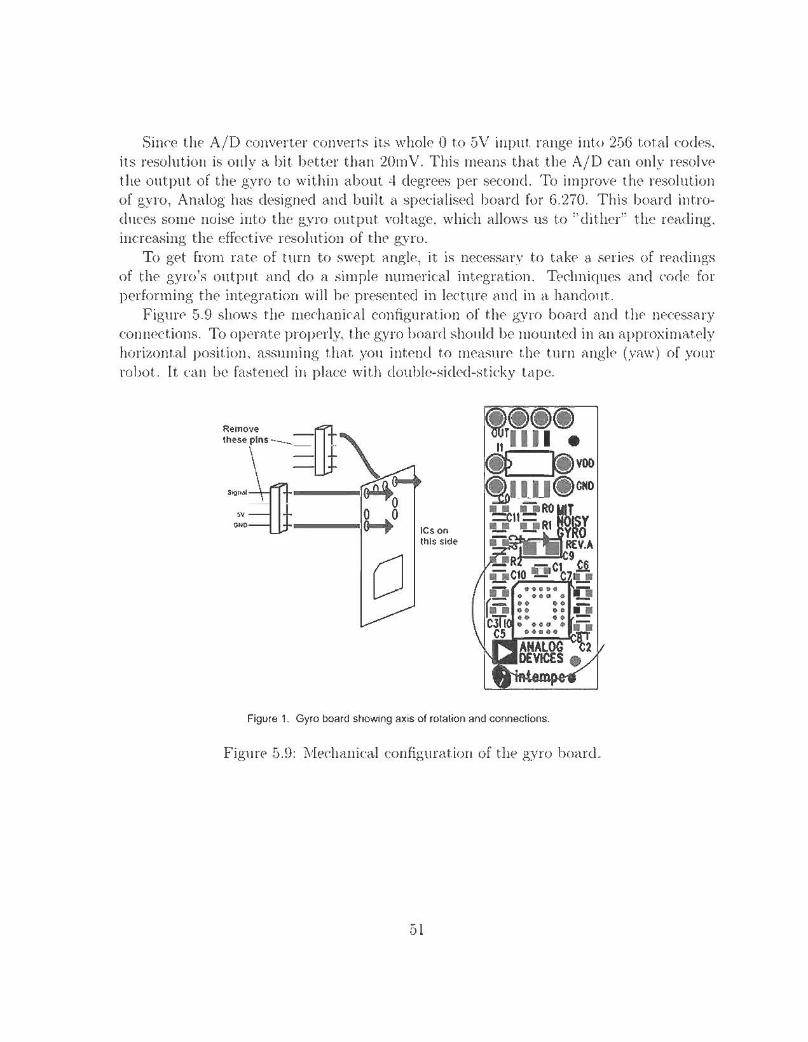
Chapter 6
Robot Construction
Most people consider LEGO to be a childhood toy, but the LEGO Technic system provides an excellent construction material for building robots. Since the pieces can be taken apart as easily as they are put together, no design must ever be final. It frees you from drawing out detailed plans and machining parts, so you can spend more time learning about and designing your robot. You can experiment with building, redesigning, and rebuilding components of your robot until you are satisfied with the results.
The best way to learn how to build with LEGO pieces is to play with them, but this chapter will present an introduction to a number of building techniques and design ideas. It is meant to provide you with the basic knowledge you will need to begin exploring and learning on your own. Reading this chapter, however, is no substitute for actual hands-on experience.
6.1 Design Concepts
When beginning work on a task as complex as building a robot, it helps to follow good design techniques. Although it requires continual practice to hone these skills, keeping the following ideas in mind while you build can help you produce a successful robot:
• Simplicity. The best way to build a reliable robot is to keep it as simple as is reasonably possible. In general, the more complicated a design is, the harder it is to build, and the more prone it is to failure. Try to minimize the number of moving parts and the overall complexity of the robot.
• Strength. During the course of operating and transporting your robot, it will be bumped and handled quite often. This can easily damage the robot and cause
53
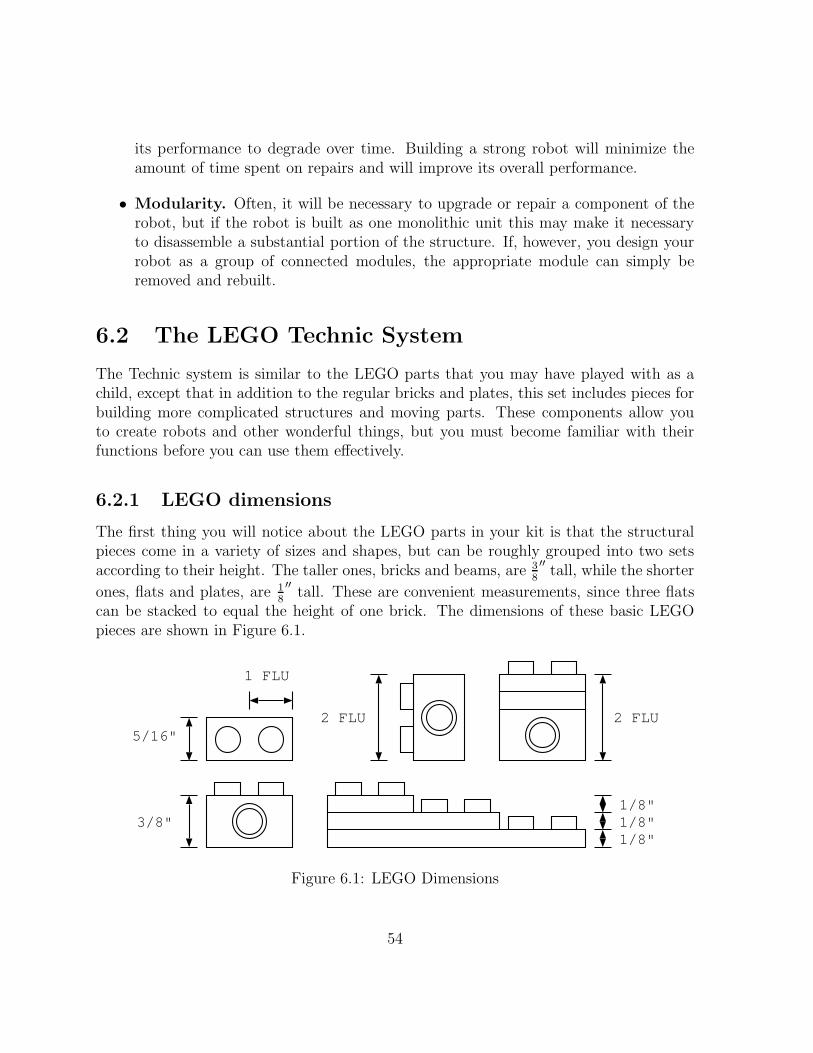
its performance to degrade over time. Building a strong robot will minimize the amount of time spent on repairs and will improve its overall performance.
• Modularity. Often, it will be necessary to upgrade or repair a component of the robot, but if the robot is built as one monolithic unit this may make it necessary to disassemble a substantial portion of the structure. If, however, you design your robot as a group of connected modules, the appropriate module can simply be removed and rebuilt.
6.2 The LEGO Technic System
The Technic system is similar to the LEGO parts that you may have played with as a child, except that in addition to the regular bricks and plates, this set includes pieces for building more complicated structures and moving parts. These components allow you to create robots and other wonderful things, but you must become familiar with their functions before you can use them effectively.
6.2.1 LEGO dimensions
The first thing you will notice about the LEGO parts in your kit is that the structural pieces come in a variety of sizes and shapes, but can be roughly grouped into two sets
′′according to their height. The taller ones, bricks and beams, are 3
8tall, while the shorter
′′ones, flats and plates, are 1
8tall. These are convenient measurements, since three flats
can be stacked to equal the height of one brick. The dimensions of these basic LEGO pieces are shown in Figure 6.1.
5/16"
3/8" 1/8"
1/8" 1/8"
2 FLU2 FLU
1 FLU
Figure 6.1: LEGO Dimensions
54
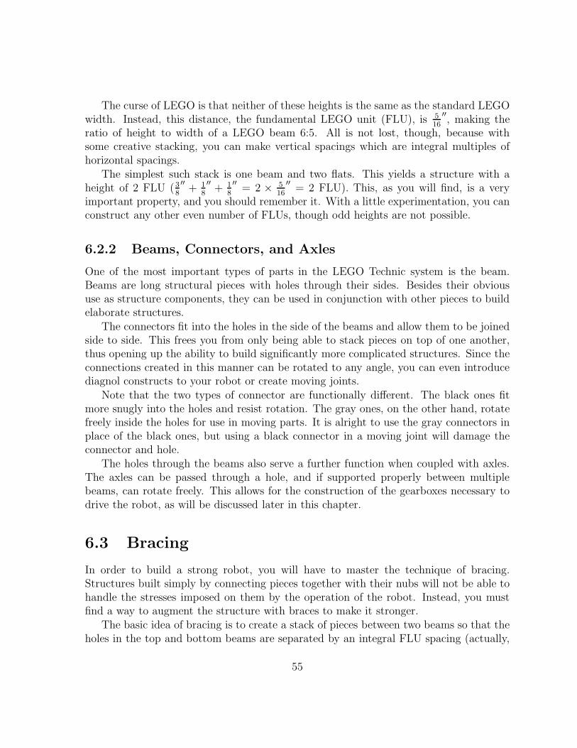
The curse of LEGO is that neither of these heights is the same as the standard LEGO ′′
width. Instead, this distance, the fundamental LEGO unit (FLU), is 5
16 , making the
ratio of height to width of a LEGO beam 6:5. All is not lost, though, because with some creative stacking, you can make vertical spacings which are integral multiples of horizontal spacings.
The simplest such stack is one beam and two flats. This yields a structure with a ′′ ′′ ′′ ′′
height of 2 FLU (3
8+ 1
8+ 1
8 = 2 ×
5
16 = 2 FLU). This, as you will find, is a very
important property, and you should remember it. With a little experimentation, you can construct any other even number of FLUs, though odd heights are not possible.
6.2.2 Beams, Connectors, and Axles
One of the most important types of parts in the LEGO Technic system is the beam. Beams are long structural pieces with holes through their sides. Besides their obvious use as structure components, they can be used in conjunction with other pieces to build elaborate structures.
The connectors fit into the holes in the side of the beams and allow them to be joined side to side. This frees you from only being able to stack pieces on top of one another, thus opening up the ability to build significantly more complicated structures. Since the connections created in this manner can be rotated to any angle, you can even introduce diagnol constructs to your robot or create moving joints.
Note that the two types of connector are functionally different. The black ones fit more snugly into the holes and resist rotation. The gray ones, on the other hand, rotate freely inside the holes for use in moving parts. It is alright to use the gray connectors in place of the black ones, but using a black connector in a moving joint will damage the connector and hole.
The holes through the beams also serve a further function when coupled with axles. The axles can be passed through a hole, and if supported properly between multiple beams, can rotate freely. This allows for the construction of the gearboxes necessary to drive the robot, as will be discussed later in this chapter.
6.3 Bracing
In order to build a strong robot, you will have to master the technique of bracing. Structures built simply by connecting pieces together with their nubs will not be able to handle the stresses imposed on them by the operation of the robot. Instead, you must find a way to augment the structure with braces to make it stronger.
The basic idea of bracing is to create a stack of pieces between two beams so that the holes in the top and bottom beams are separated by an integral FLU spacing (actually,
55

only even numbers are possible). Then, using the connectors, you attach a beam vertically alongside the stack so that it holds the pieces together. Such a stack can be built in a number of ways, but a simple one is shown in Figure 6.2. The concept is simple but important for building an effective robot.
beam
flat
beam
flat
Figure 6.2: A Simple Braced Structure
Since bracing imposes constraints on how a structure can be built, it will be necessary to consider how your robot’s structure will be braced from very early on in the design process. With experience, you will be able to build robots which can carry heavy loads and resist falling apart even when dropped on the floor. You will also be able to determine where braces are needed (and also of importance, where they are not).
6.3.1 Drop Testing
How do you know if your structure is strong or not? If you are daring, drop it on the floor from about waist height. If it shatters into little pieces, it failed the test. If it only suffers minor damage which can be easily repaired, you can be fairly certain that it can handle the rigors of everyday life. In the past, some particularly strong robots have been known to drive off of tables and still be in working condition.
Drop test at your own risk.
6.4 Gears
Most electric motors are really lacking in torque, or in other words, they cannot push very hard. If you hook a wheel directly up to the motor’s shaft, you will find that it can hardly turn the wheel, let alone budge an entire robot. What they do have a lot of, though, is speed. In fact, when you let the shaft run freely, it can spin at a rate of
56
thousands of revolutions per minute. This is much faster than you want your robot to drive anyway, so you will have to build gearboxes to trade some of this speed for more torque.
LEGO
LEGO
4040
24
LEGO
8-tooth
24-tooth
40-tooth
Figure 6.3: LEGO Gears
The LEGO Technic system contains a wide variety of gears with varying functions, but for building simple gearboxes, you will mostly rely on the 8, 24, and 40-tooth gears shown in 6.3. These are the most efficient and easiest to use of the bunch because their diameters are chosen such that they can be meshed with each other at regular LEGO distances. It is recommended that you begin by using only these gears at first, and then only use the other gears when you become an experienced builder.
6.4.1 Gearboxes
Gear reductions allow you to convert speed into torque (or vice versa by applying this technique in reverse). Suppose an 8-tooth gear is used to turn a 24-tooth gear. Since the smaller gear must rotate three times to turn the large one once, the axle with the 24-tooth gear spins slower than the other. In exchange for this decrease in speed, the axle is able to exert three times as much torque. This produces a gear reduction of 3:1, which means that you are giving up a factor of three of speed in exchange for producing three times the torque.
When a single gear reduction is not enough, it is possible to cascade a number of reductions in a gear box to achieve a higher gear ratio. For example, in Figure 6.4, two 3:1 and one 5:1 gear reductions are combined to create a 45:1 (3x3x5:1) gearbox. This means that the leftmost axle must turn 45 times in order to turn the rightmost axle (the output shaft) one time. If a motor with an 8-tooth gear was used to turn the 24-tooth gear on the leftmost axle, this would add another 3:1 reduction, bringing the total reduction 135:1.
57

8
24
40
8
8
24
24
output shaft51545 : : : 1
Figure 6.4: A LEGO Gearbox
There is no simple guide for choosing the gear ratio of a gearbox because it depends very heavily on the application. For heavy loads, high gear ratios will provide more force, but at the expense of speed. For fast, light robots, however, a lower gear ratio would be more appropriate. In order to find the correct match for your robot, you will have to experiment with a number of possible ratios.
6.4.2 Strange Gears
Occasionally, you will run into situations where the basic three gears are inadequate. In these cases, you may find that one of the strange gears will fit the purpose. You should use these gears sparingly, since they tend to be inefficient and prone to mechanical failure, but when they are needed, they can be life savers.
• 16-tooth gears are just like the basic three described above, except that they only mesh straightforwardly with other 16-tooth gears. They are very efficient, but because of their antisocial behavior are only really useful for transferring force with no gear reduction.
• Worm gears look like cylinders with a screw thread wound around them. They act like a 1-tooth gear and are useful for building small, high-ratio gearboxes. They are extremely inefficient and tend to wear down quickly when subject to anything but the lightest loads. Avoid using these gears whenever possible and never use them in a robot’s drive train.
• Angle and crown gears look similar to the standard gears, except that they have angled teeth. This allows them to be meshed at 90 degree angles with other gears,
58
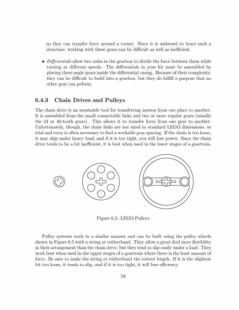
so they can transfer force around a corner. Since it is awkward to brace such a structure, working with these gears can be difficult as well as inefficient.
• Differentials allow two axles in the gearbox to divide the force between them while turning at different speeds. The differentials in your kit must be assembled by placing three angle gears inside the differential casing. Because of their complexity, they can be difficult to build into a gearbox, but they do fulfill a purpose that no other gear can peform.
6.4.3 Chain Drives and Pulleys
The chain drive is an invaluable tool for transferring motion from one place to another. It is assembled from the small connectable links and two or more regular gears (usually the 24 or 40-tooth gears). This allows it to transfer force from one gear to another. Unfortunately, though, the chain links are not sized to standard LEGO dimensions, so trial and error is often necessary to find a workable gear spacing. If the chain is too loose, it may skip under heavy load, and if it is too tight, you will lose power. Since the chain drive tends to be a bit inefficient, it is best when used in the lower stages of a geartrain.
Figure 6.5: LEGO Pulleys
Pulley systems work in a similar manner and can be built using the pulley wheels shown in Figure 6.5 with a string or rubberband. They allow a great deal more flexibility in their arrangement than the chain drive, but they tend to slip easily under a load. They work best when used in the upper stages of a geartrain where there is the least amount of force. Be sure to make the string or rubberband the correct length. If it is the slightest bit too loose, it tends to slip, and if it is too tight, it will lose efficiency.
59

6.4.4 Efficiency
The biggest enemy of any gearbox is friction. Every place where something rubs, energy is lost which makes your robot slower and weaker. In the short-run, this causes your robot to perform poorly, but in the long-run, it will cause wear and tear on the moving parts. More damage means more friction, and after awhile, the gearbox will stop working. In order to minimize the amount of friction in your gearbox and maximize its efficiency, follow the tips below:
1. The spacing between gears is very important. If they are too close to each other, they will bind up. If they are too far, the teeth will slip past each other. Make sure that gears are spaced at exact LEGO dimensions and avoid meshing gears at an angle.
2. The axles are made out of plastic and can bend if not properly supported. Try to always support the axle between two beams and do not place a gear more than one space outside of the supports.
3. The gearbox will often be subjected to stresses when used within a robot. Make sure that the beams supporting the axles are attached to each other with more than one cross-support and that the whole structure is braced. If the beams are not perfectly parallel, the axles will rub against the insides of the holes.
4. During operation the gears can slide along the axle or bump into nearby gears. Use spacers to fill in any empty spots along the axle.
5. Make sure that the axles can slide back and forth a tiny bit. If they cannot, the gears or spacers are probably pushing up against a beam. This is probably the most common (and easiest to fix) mistake which saps efficiency from a gearbox.
If you want to know how good your gearbox is, try backdriving it. Remove the motor and try to turn the output shaft (the slow axle) by hand. If your geartrain is efficient, you will be able to turn all the gears this way, and if it is really efficient, they should continue spinning for a second or two after you let go. If your gearbox cannot be backdriven, something may be wrong with it.
6.5 Drive Mechanisms
Perhaps the single most important aspect of a robot’s physical design is its drive system. It is responsible for moving the robot from place to place by providing the appropriate motive force and steering mechanisms. Figure 6.6 shows the three most popular drive arrangements.
60

differential steering synchro
drive wheel
steering wheel
steering and drive wheel
Figure 6.6: Popular Drive Arrangements
6.5.1 Differential Drive
A differential drive is much like the drive mechanism on a tank. It consists of two independently driven wheels arranged side by side. When both wheels are driven at the same rate in the same direction, the robot will move straight. When the wheels are driven at the same rate in opposite directions, the robot will spin in place. By varying the relative speeds of the two wheels, any turning radius is achievable. Since this system minimizes the number of moving parts, it tends to be the simplest and most robust. The complexity is increased slightly, though, by the need for a caster in the front or back of the robot to keep it from tipping over.
An especially useful property of this drive system is that the change in orientation of the robot depends only on the difference between the distances travelled by each of the wheels. It does not matter if the left wheel moves forward 10cm and the right back 10cm, or if only the left wheel moves forward 20cm; the final location will be different, but the orientation will be the same (ignoring slippage). This greatly simplifies the process of turning, by making the final orientation of the robot easily predictable.
The differential drive is the most popular because of its simplicity, though it does have some limitations. Since it is difficult to calculate the final location of the robot if it turns and moves at the same time, most navigation algorithms consist of driving straight for a distance, turning through a specified angle in place, and then driving straight again. More sophisticated algorithms allow the robot to turn while moving, but typically, such turns are still constrained to easily calculated curves.
61

6.5.2 Steering System
Steering systems should already be familiar to you because they are widely used in automobiles. They usually consist of one or two steerable wheels at the front of the robot and two powered wheels at the rear. The turning radius is determined by the angle of the steerable wheels, but the robot must be moving in order to make a turn. This means that it cannot turn in place and can only make turns of limited sharpness while driving.
The advantage to using a steering system comes from the separation of the steering and drive mechanisms. Such robots tend to be quick and fairly agile. They are well-suited to driving in open spaces or performing ”follow” tasks since these tasks usually require making course corrections to the left and right as the robot drives. When a steering robot turns, though, the two rear wheels will take paths of different lengths. The outer one will travel a longer distance than the inner one, so it is helpful to use a differential in the gearbox to transfer force between the wheels in order to avoid slippage.
6.5.3 Synchro Drive
The synchro drive is an exotic mechanism where all the wheels are driven and steered together. Usually, there is one gearbox which turns the wheels to the desired orientation and then another which drives the robot in that direction. This may seem strange, but it allows the robot’s instructinos to be phrased in terms of world coordinates, instead of having to compute everything in terms of the robot’s perspective. The robot can also be commanded to move in any direction, making this the most mobile of the drive systems.
This mechanism simplifies control at the expense of complexity in construction. All the wheels must be both steerable and drivable, so building drivetrains for such a system often requires an elaborate system of gears and chain drives. Also, since only the wheels turn, the robot’s body remains in a fixed orientation, unless it is also turned. This makes it inconvenient for such a robot to have a front as many applications require.
6.5.4 Legs
Robots with articulate legs can do everything that a wheeled robot can do and more. This includes walking in arbitrary directions, turning in place, and even climbing over otherwise inaccessible terrain. Unfortunately, though, legged robots are prohibitively difficult to build out of LEGO and comparably difficult to control. In fact, a great deal of research is currently being performed to study ways of making robots walk. If you think you are up to the challenge, a legged robot makes a very exciting project, but be warned that building legs can be much more difficult than it appears.
62

Chapter 7
Robot Control
To the uninitiated, the term “robot” conjures up images of machines with human-like abilities. Unfortunately, technology has not yet reached the point where robots can mimic the intelligence of humans. Instead, the robot that you will be constructing will require simple, step-by-step instructions for completing even the most simple of tasks.
A robot’s ability to interact with the environment centers around its sensors and control system. The sensors convert information about the environment into a form that can be used by a computer. They are limited in their abilities, however, and often give back information that is cryptic, ambiguous, or even inaccurrate. The control system must decode this information and determine the best course of action. The task of endowing the control system with these abilities falls to you, the programmer. This chapter will explore the design of systems for controlling a robot in a constantly changing and unpredictable environment.
7.1 Control Systems
Control systems is an entire field of study and reducing it to one section of one chapter of one book certainly does not do it justice. The material presented here covers only the very basic concepts, but for this course, it will be sufficient for your needs. If you are interested in understanding these concepts in more depth, there are many relevant courses and a large body of literature dedicated to the subject.
63

7.1.1 Open Loop
The most obvious approach to programming a robot is to give it a sequence of instructions to follow. The robot then executes its orders without worrying about the consequences of its actions. Information flows only from the controller to the actuators to the world as shown in Figure 7.1.
controller actuators world
Figure 7.1: Open loop information flow
Although the controller can send commands to the actuators, it cannot tell whether or not the correct action occurred. Information flows from the controller to the world, but not back again. For this reason, such a system is known as open loop control. Open loop control is rarely used in the real world because it lacks robustness. Small changes in the robot and environment cannot be accounted for, and after awhile, error begins to build up. Even the smallest errors will eventually build up to a point that the robot
start finish start finish
forward 8 seconds
forward 5 secondsfo
rwar
d 5
seco
nds
right 3 seconds
right 3 seconds
becomes lost.
Figure 7.2: A robot trying to navigate with open loop control
Consider, for example, the path the robot must take to navigate the course in Figure 7.2. On the left is the path that the robot is supposed to follow labelled with the appropriate instructions. As the batteries lose power, though, the speed of the robot will
64

decrease. Since the durations of each action are no longer valid, the robot might take the path shown at right, leading to a collision with the wall. Clearly, open loop control is not going to get the job done.
7.1.2 Feedback
To avoid the problem from above, the robot needs to take advantage of some of the information available in the environment. The robot can use its sensors to correct errors and compensate as needed before the situation gets out of control. This closes the loop of information flow, as shown in Figure 7.3.
controller actuators world
sensors
Figure 7.3: Closed loop (feedback) information flow
The feedback approach requires a different way of thinking about the problem. Rather than performing a single action designed to move the robot to its goal, the robot repeatedly makes small corrective actions in response to its current situation. Through repetitive application of these small maneuvers, the robot eventually achieves its overall desired goal.
Figure 7.4 shows how the robot can apply feedback control to the situation from above. In this example, the robot is repeatedly applying the following set of rules:
1. If the front of the robot is in contact with a wall, back up to the right.
2. If the left of the robot is in contact with a wall, turn right.
3. If the right of the robot is in contact with a wall, turn left.
4. Otherwise, drive forward.
65

start finish
Figure 7.4: A robot using feedback to navigate
Rule 4 is the default behavior of the robot. Whenever it is out in the open, it simply drives forward. Rules 2 and 3 allow the robot to drive down a corridor. Whenever it bumps into one of the walls, it turns away from it and continues down the corridor. Rule 1 turns the robot when it reaches a corner. The robot repeatedly runs into the wall and backs away from it, each time turning a little bit more. After a few collisions, the robot completes the turn and continues down the next segment of the course.
With this algorithm, a number of assumptions about the robot’s performance have been relaxed. It does not matter how fast the robot moves or even if it drifts a bit to one side as it drives. The algorithm is now much more robust because there are less unseen factors in the environment and the robot that can make it perform incorrectly. The use of feedback has greatly improved the design.
7.1.3 Open Loop Revisited
The primary drawback to using feedback is that some tasks require a large amount of time to complete. In the feedback example above, the robot had to make a number of forward and backward motions in order to go around a corner. This takes a lot of time and can be a major handicap for speed-critical applications. It would be nice if there was a way to turn more quickly.
Fortunately, open loop control may be good enough for some situations. Instead of the feedback-only algorithm, a hybrid algorithm can be used as in Figure 7.5. The robot navigates the corridor using the feedback algorithm, except that when it runs into a wall, it backs up a little and performs the quicker open loop turn instead of the bumping method. After completing the turn, it then returns to the feedback algorithm for navigating the next corridor.
As long as the open loop turn is accurate enough that the robot does not get stuck
66

start finish
back 1 second, right 3 seconds
back 1 second, right 3 seconds
Figure 7.5: A robot combining open loop and feedback control
in a corner, the feedback mechanism will be able to compensate for any error that it introduces. Since the error is erased in this manner before the next open loop command, it cannot snowball out of control like in the purely open loop algorithm. By using this clever sandwiching of open loop and feedback control, it is possible to develop an algorithm that has most of the efficiency of open loop control while only sacrificing a little of the robustness of feedback control.
7.2 Sensors
Sensors allow a robot to collect information about the environment. They convert physical measurements from the world into electrical signals that can be understood by the controller. This gives the robot a link to the real world allowing it to respond appropriately to changes in its environment.
7.2.1 Sensor Problems
The real world is a noisy place compared to the digital world of a computer, and in robotics, this noise can make sensor readings unreliable. Sensor data mirrors the nonideal nature of the robot’s environment and must be interpreted by the computer. Below are a few of the common types of errors that appear when reading sensors:
• Glitchy data is often a problem due to faults in the sensor hardware. When a glitch occurs, the sensor may return an unexpected value or a value outside of the range of possible values. Often, loose connector plugs or shorted wires can cause spurious input by intermittantly losing or making contact. This can be identified and fixed in software by ignoring values that fall outside of the expected input.
67

• Noisy data is a problem for most sensors. The world is full of flickering lights, uneven surfaces, and magnetic fields which can all cause errors in measurements. Since noise tends to be a random process, there is no way to predict it, but its effects can be minimized by averaging multiple values together when reading a sensor.
• Drifting data is often the result of sensors retaining some sort of memory. This problem is particularly prominant in light sensors which are affected by changes in the ambient lighting of the room. As the robot moves from place to place, the amount of light reaching the sensor can vary and change the range of the measurements. Some light sensors are also sensitive to heat and return different values as they warm up. These effects occur slowly over time, so they can be very difficult to detect. One option is to give the robot the ability to recalibrate itself whenever it finds itself in a known situation. This way, calibration values can be updated on the fly as the robot moves from one part of the environment to another.
7.2.2 Bouncing Switches
When a mechanical switch closes, two conductive contacts are physically brought together. When they first touch lightly, conduction may be intermittent due to the presence of insulating contaminants on the contact surfaces. Even after good contact is established, the contacts may momentarily separate and reconnect one or more times as a result of the movable contact bouncing after it lands (the moving part of a switch is usually somewhat springy and has nonzero mass, so it resonates). Intermittent contact can also occur as a switch opens. All of these phenomena are generally lumped under the heading of ”switch bounce”. They all give the appearance of multiple switch events when only one actually occurred. All of these effects also respond to the same treatment: after the first detected closing or opening of a switch, wait an appropriate amount of time (10ms - 20ms is usually sufficient) and then check again to see if the contact is still closed (or open). Adjust the delay time until you reliably detect a single event for a single motion of the switch. It is also possible to check several times over shorter time intervals if time is critical in your application.
7.2.3 Calibration
Light sensors are particularly sensitive to changes in the world. Differences in ambient lighting from one room to another can wreak havoc on the readings that the sensor returns. When the robot needs to be moved from one environment to another, calibration is often necessary to adjust the settings used to interpret the data.
Even though most light sensors are analog in nature, you will often use them as if they were digital sensors. Rather than asking the question, “How bright is it?,” you will
68
instead ask “Is it light or dark?” The goal of calibration, then, is to choose a threshold value which will separate light values from dark values.
The most common way to choose a threshold is to take readings in a controlled situation, such as during a calibration routine. By averaging two readings, one for light and one for dark, a value can be chosen to separate the two conditions. Then, each time a the sensor takes a reading, it can be compared to the threshold to determine if the sensor is seeing light or dark.
7.3 Simple Navigation
Robot navigation is a difficult problem, but it can often be decomposed into a number of subtasks. These simple tasks can be implemented with feedback mechanisms and represent the basic skills that most 6.270 robots utilize as part of their grand strategy. Calling them “simple,” however, is a bit misleading because, as you will see, making them work together reliably requires a lot of fine tuning and patience.
7.3.1 Wall Following
Imagine yourself in a dark hallway. You have to get to the other end, but you cannot see anything. What do you do? If you are like most people, you probably begin by finding one of the walls with your hand. Then, as you walk, whenever your hand detects that you are too close to the wall, you move farther from it, and when you are too far, you move closer. This, it turns out, is pretty much the way your robot will do it.
Wall following is very simple because it only requires a single sensor mounted on one of the front corners of your robot. This sensor will deliver just one bit of information which determines whether the robot is touching the wall or not. To follow the wall, the robot then executes the algorithm mentioned above:
• If the robot is touching the wall, turn away from the wall.
• If the robot is not touching the wall, turn towards the wall.
This will cause the robot to repeatedly bump into the wall, as shown on the left side of Figure 7.6, alternately activating and releasing the sensor. This oscillation can be minimized by tuning how sharply the robot turns or by using a sensor which gives more precise distance information.
While following the wall is easy, finding it in the first place can often be difficult. If the robot begins close enough to the wall, it can simply use the wall following algorithm to find it. If the robot approaches the wall at a steep angle, however, it is likely to jam. When the robot’s initial position is unpredictable, it is advisable to use some strategy for aligning with the wall before trying to follow it.
69

wall follow
wall fo
llow
Figure 7.6: Wall following and a jammed robot
7.3.2 Line Following
Line following is usually accomplished by mounting one or more reflectance sensors on the underside of the robot. By measuring the intensity of the reflection, these sensors can determine whether they are over a light or dark area. By adding a little “intelligence,” the robot can be made to follow lines.
The number of sensors and the configuration used depends on the robot and application, but the method is almost always the same. The sensors detect when the robot begins straying from the line, and the controller issues orders to correct for the error. Developing this algorithm begins with constructing a chart of all possible combinations of sensor inputs and the appropriate action for each. This information can then easily be coded into the robot’s program.
Left
Mid
dle
Rig
ht
Action
Lef
t
Mid
dle
Rig
ht
Action
LEFT! LEFT!n/a
RIGHT! RIGHT! n/a
right n/a off
Sensor Inputs
on
Figure 7.7: Line following with 3 reflectance sensors
stra
ight
left
Figure 7.7 shows the table for constructing a program for a robot with three reflectance sensors arranged in a line across the robot with the left and right ones spaced wider than the line. Whenever the robot begins to drift, one of the outer sensors detects the line and tells the robot to correct itself. If the robot continues to stray, the middle sensor loses the line and tells it to turn sharper. It is interesting to note that in theory, some of the
70

states cannot occur, but in practice, erroneous sensor readings and unexpected situations can cause them to arise. It is usually wise to assign best-guess actions to these states to make sure that the robot always has something to do.
7.3.3 Shaft Encoders
Shaft encoders are a wonderful tool for robot navigation. When placed on a wheel or in the wheel’s accompanying gear box, encoders can very accurately measure the distance the wheel has travelled. This provides the robot with a number of abilities, including measuring distances, driving straight, and turning accurately.
LEDphototransistor
Figure 7.8: Shaft encoding using a LEGO pulley wheel
A shaft encoder is constructed from a breakbeam sensor and a Lego pulley wheel as shown in Figure 7.8. As the wheel turns, the holes in the wheel alternately allow and then block the light from hitting the detector in the sensor. The robot can then count the number of passing holes and compute how far the wheel has turned.
If both sides of the robot are driven at the same rate, the robot will move in a straight line. For a robot with a differential drive system, the easiest way to do this is to place a shaft encoder into each of the drive trains and monitor the distance each wheel has travelled. Whenever one wheel gets ahead of the other, it is slowed down.
The problem of driving straight can be solved with a very simple algorithm. Whenever the left side of the robot is ahead, the right wheel is driven faster, and the left is slowed down. When the right side of the robot is ahead, the opposite action is taken. The robot constantly corrects for small deviations allowing it to drive in a straight line.
Shaft encoders are so useful that many robots make extensive use of them, but they are not the entire solution to robot navigation. The feedback provided by the encoders comes not from the environment, but rather from within the robot. Slippage of the
71
wheels on the floor is not accounted for, and can lead to measurement errors, especially when turning. In order to correct for these errors, additional feedback mechanisms must be used in conjunction with the shaft encoders.
7.4 Timeouts
Control systems often fail when something unexpected happens, and the available sensor information is not able to account for the situation. Most of the time, when a robot gets lost, it will wind up stuck on some obstacle. If none of the sensors register the collision, the robot will not even know that anything is wrong. It will continue trying to drive, oblivious to the fact that it is not getting anywhere. If the robot does not reach its goal after a certain amount of time, though, it can usually assume that a problem has occurred along the way.
When an action times out, the robot only knows that something has gone wrong, but not what it is. Regardless, the robot can often act to increase its chances of recovering. In many cases, backing up a little or thrashing around may be sufficient to free the robot from an obstacle so that it can continue on its course. In any case, detecting that something has gone wrong can considerably increase the robots ability to make the best of a bad situation.
72

Appendix A
IC commands for 6.270
The Interactive C Manual For the Handy Board describes the basic set of commands you will have access to on the Handy Board. In addition, to make use of the 6.270 expansion board, you will need to use several extensions to the standard IC library, described in this appendix.
A.1 Expansion Board: Motors, Analog Inputs, Dig
ital Outputs
There are two motor ports on the expansion board, numbered 4 and 5. You can use them just as you use the motors on the main board:
fd(4);motor(5,-100);/* etc... */
Since the expansion board motors are not speed-controlled, all positive speeds and all negative speeds are equivalent to 100 and -100, respectively.
The expansion board add 16 analog inputs, labelled 16–31. They are used just like the analog ports on the main board:
analog(23);
When the expansion board is in use, ports 1 and 2 on the main board can’t be used. There are three digital outputs: do0, do1, and do2, which correspond to ports 8,
7, and 6 in software respectively. To turn the three digital outputs on and off, use the following commands:
set_digital_out(p);clear_digital_out(p);
73

where p is replaced by whatever port you wish to control.
A.2 Expansion Board: Servos
The expansion board has the ability to control up to six servos. To turn on the servos, run the following command:
enable_servos();
To turn off servo power, run this:
disable_servos();
The function servo(int port, int period) sets the servo to an angle that depends on period, which can vary from 0 to 4000.
A.3 Using the RF Reciever
Connect your RF receiver to the phone jack on your handyboard using the telephone cable. To enable the RF receiver, use the following command:
rf_team = YOURTEAMNUMBER;
rf_enable();
The IC libraries include code to detect the start of the match. Call the procedure start_machine() when your robot is ready to begin. The code will walk you through the starting routine, consisting of the following steps:
• Your LCD will display a message as soon as it has heard an announcement from the RF system. This should happen within a second.
• Announce ”ready to go” and step back.
• When the match begins, start_machine() will return. Start doing stuff!
• When the match ends, start_machine() will automatically shut down your robot.
The following is the basic outline for a program that follows the rules of 6.270.
74

void main() {
rf_team = 1;
rf_enable();
/* calibrate your robot... */
start_machine();
printf("GO!\n");
/* your code goes here... */}
Additionally, the RF system provides a number of variables giving you information about the match in progress:
• rf_x0, rf_y0, rf_x1, rf_y1
The x and y positions of robots 0 and 1, respectively. Note that there is no guarantee about which team is robot 0 – you must figure out which robot (0 or 1) is your team and which is the other.
• rf_vote_red, rf_vote_green
The current number of votes for red and green, respectively.
• rf_vote_winner
The current color that is winning the vote – 0 if red, 1 if green.
75
Appendix B
Expansion Board Assembly
While the main board comes fully assembled, you will have to assemble the newer expansion board yourself. If you are not familiar with soldering, please attend the soldering workshop to learn the basics, and if you have any further questions, no matter how small, please contact a member of the staff before you proceed. We’ll be much happier if you come to us before you’ve made a mistake than afterward. That said, building the expansion board should not be much of a challenge for anyone, and we recommend that you get started on it as soon as possible, and not fall behind. The circuit board may look complicated, but do not despair! Many of its parts (such as circuitry to make it compatible with LEGO Mindstorms sensors) are optional and not needed for 6.270.
Although missing LEDs and the sockets for some ICs the board is functional. Also visible is the beacon power/signal cord, which will not be used for this years contest.
77