may 2018 safety recall u04 / nhtsa 18v-160 frame bracket
TRANSCRIPT

Copyright 2018, FCA US LLC, All Rights Reserved (kka)
May 2018 Dealer Service Instructions for:
Safety Recall U04 / NHTSA 18V-160
Frame Bracket
NOTE: Effective immediately all repairs on involved vehicles are to be
performed according to this notification. Service Bulletin (TSB) # 1400218 is no
longer applicable for the involved vehicles.
NOTE: This safety recall is regional campaign; please reference the dealer
policy manual regarding handling of customers within a regional recall. Also,
see Regional Information section below.
2009 - 2012 (DS) RAM 1500 Pickup
2009 - 2012 (DX) Dodge Reg Cab Chassis (Mexico)
NOTE: This campaign applies only to the above vehicles built from May 28, 2008
through September 07, 2012 (MDH 052807 through 090701).
The front fuel tank strap on about 287,000 of the above vehicles may detach due to
the frame bracket corroding. Detachment of the front fuel tank strap could
potentially allow the front of the fuel tank to make contact with the ground,
increasing the risk of a fuel leak. A fuel leak in the presence of an ignition source
could result in a fire.
Remedy Available
IMPORTANT: Some of the involved vehicles may be in dealer used vehicle
inventory. Dealers should complete this recall service on these vehicles before
retail delivery. Dealers should also perform this recall on vehicles in for service.
Involved vehicles can be determined by using the VIP inquiry process.
Subject
Safety Recall U04 – Frame Bracket Page 2
A fuel tank strap reinforcement bracket must be installed on all involved vehicles.
If the old fuel tank strap was disconnected from the original frame bracket, replace
the front and rear fuel tanks straps with NEW fuel tank straps and locking nuts.
Dealers should attempt to minimize customer inconvenience by placing the owner
in a loaner vehicle if inspection determines that repair is required and the vehicle
must be held overnight.
Part Number Description
68418923AB Kit, Fuel Tank Strap Mounting Bracket
Each package contains the following components:
Quantity Description
1 Fuel Tank Strap Mounting Bracket
4 Rivnuts
4 Fasteners, Mounting Bracket
Part Number Description
04443633 *Spray Primer or Equivalent
04443609 *Spray Paint, Black
55398298AA Strap, Fuel Tank Front (Only if Needed)
55398299AA Strap, Fuel Tank Rear (Only if Needed)
06104717AA Nut, Hex Flange Lock, M10x1.50 (Qty of 2)
*Note: Each can of primer and spray paint will service
approximately 25 vehicles.
Repair
Alternate Transportation
Parts Information

Safety Recall U04 – Frame Bracket Page 3
Some vehicles, not originally sold or currently registered in the selected region,
may experience the same condition that is the subject of the limited service or
recall campaign (e.g., vehicles located in “border states”, vehicles regularly driven
in states included in the recall, etc.). If a vehicle exhibits such a condition, refer to
the subject Recall, CSN or Warranty Extension and verify the vehicle meets all of
the following 3 criteria:
• The vehicle built date falls within the built date range identified on the
service or recall campaign notice; and
• The vehicle is identical (year, model, make, sales codes, etc.) to the vehicles
identified on the service or recall campaign notice; and
• The vehicle exhibits the same condition(s) that is identified on the service or
recall campaign notice.
For vehicles that meet all the above 3 criteria, the Dealer must perform the service
or recall campaign work at “No Cost” to the customer. All decisions authorized by
Dealership Management must be properly documented on the repair order
including Service Management initials, date and reason for the repair.”
Only vehicles originally sold or currently registered in the following states have
been notified of this recall.
Connecticut Massachusetts Ohio
Delaware Michigan Pennsylvania
Illinois Minnesota Rhode Island
Indiana Missouri Vermont
Iowa New Hampshire Washington, DC
Maine New Jersey West Virginia
Maryland New York Wisconsin
Regional Information
Safety Recall U04 – Frame Bracket Page 4
The following special tools are required to perform this repair:
NPN wiTECH micro pod II
NPN Laptop Computer
NPN wiTECH Software
320-FC-P30-A John Dow Gas Caddy or Equivalant
8978 Fuel Decay Tool Kit
8978-2 5/16” fuel tube disconnect
8531-1 3/8” fuel tube disconnect
WTT106001A Tool, Rivnut Installation
WARNING: No sparks, open flames or smoking. Risk of injury to eyes and
skin from contact with fuel. Wear protective clothing and eye protection.
Risk of poisoning from inhaling and swallowing fuel. Pour fuel only into
appropriately marked and OSHA approved containers. Failure to follow
these instructions may result in possible serious or fatal injury.
WARNING: The fuel system is
under constant high pressure even
with engine OFF. Until the fuel
pressure has been properly released
from the system, do not attempt to
open the fuel system. Do not smoke
or use open flames/sparks when
servicing the fuel system. Make sure
the area in which the vehicle is being
serviced is in a well ventilated area.
Failure to comply may result in
serious or fatal injury.
Special Tools
Service Procedure
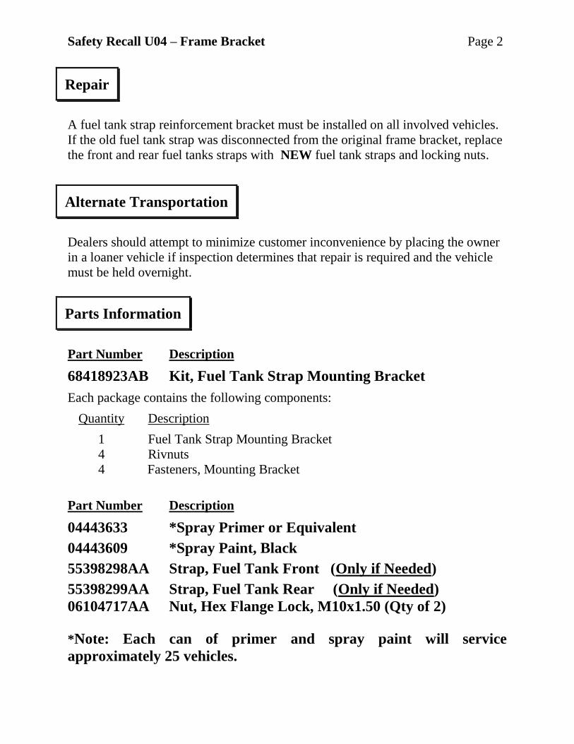
Figure 1 – Power Distribution Center
PDC COVER VEHICLE BATTERY
Safety Recall U04 – Frame Bracket Page 5
1. Align vehicle on a hoist.
2. Remove the Totally Integrated Power Module (TIPM) cover Figure 1).
NOTE: For location of the fuel pump fuse, refer to label on the underside
of the PDC cover.
3. Remove the fuel pump fuse from the TIPM.
4. Start and run the engine until it stalls.
5. Attempt to restart the engine until it will no longer start.
6. Turn the ignition to the “Off” position.
7. 3.6L engines shown for Illustration only, other engines may vary: perform
the following steps to gain access to the fuel supply tube quick-connect fitting:
a. Disconnect the Inlet Air
Temperature (IAT) sensor
(Figure 2).
b. Loosen the clamp securing the
resonator air intake tube to the
throttle body (Figure 2).
c. Release the air cleaner cover
latches (Figure 4).
d. Remove the air cleaner cover from
the lower air cleaner housing
(Figure 4).
NOTE: The resonator (engine
cover) is bonded to the air
intake tube. Do not attempt to
separate them. The resonator
and intake tube must be removed as an assembly.
Service Procedure
Figure 2 – 3.6L Air Intake Tube and Resonator Assembly
RESONATOR
IAT SENSOR
INTAKE TUBE CLAMP
INTAKE TUBE
Safety Recall U04 – Frame Bracket Page 6
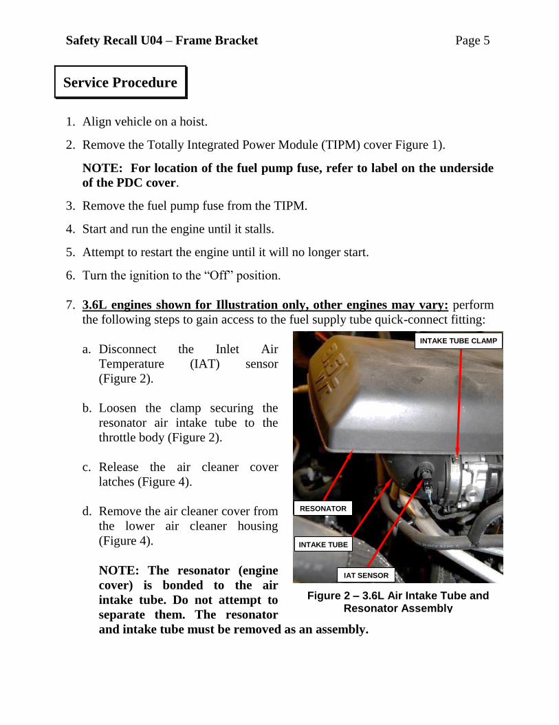
e. Pull the front of the
resonator with air
intake tube away
from the throttle
body while lifting
from the rear of the
resonator to
separate from the
ball stud mounts
(Figure 4).
Service Procedure [Continued]
Figure 4 – 3.6L Resonator and Air Cleaner Cover
RESONATOR AIR CLEANER COVER

Safety Recall U04 – Frame Bracket Page 7
8. 5.7L engines only, perform the following steps to gain access to the fuel supply
tube quick-connect fitting:
a. Disconnect the Inlet Air Temperature (IAT) sensor (Figure 5).
b. Loosen the clamps securing the clean air tube to the air cleaner housing and
throttle body (Figure 5).
c. Remove the clean air tube from the air cleaner housing and throttle body
(Figure 5).
NOTE: The engine cover front grommets are a ball stud type mount
and the rear grommets are a sliding peg design.
d. Remove the engine cover by first lifting the front of the engine cover up to
separate the engine cover front grommets from the ball studs on the intake
manifold. Then slightly raise the front of the engine cover and slide forward
to remove the rear engine cover pegs from the grommets on the rear of the
intake manifold (Figure 5).
Service Procedure [Continued]
Figure 5 – 5.7L Clean Air Tube and Engine Cover
AIR CLEANER HOUSING CLEAN AIR TUBE IAT SENSOR ENGINE COVER
INTAKE TUBE CLAMPS
Safety Recall U04 – Frame Bracket Page 8
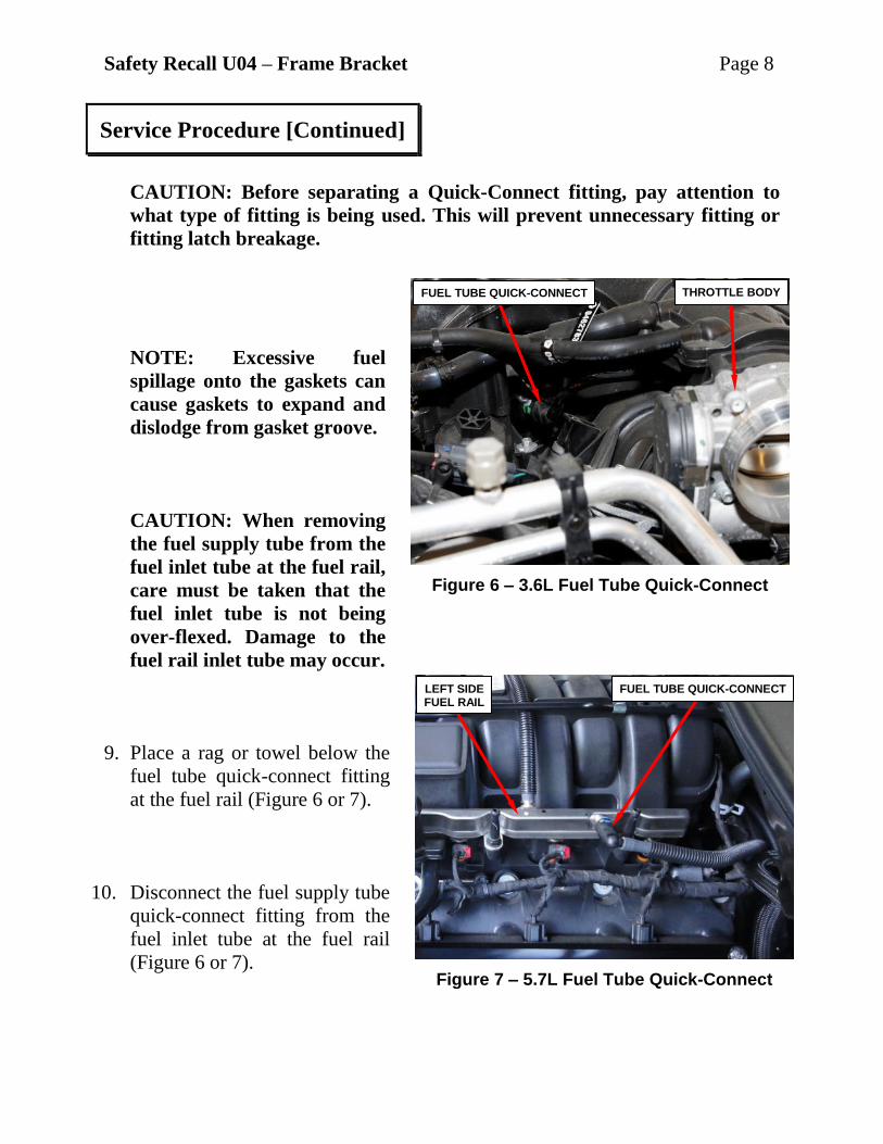
CAUTION: Before separating a Quick-Connect fitting, pay attention to
what type of fitting is being used. This will prevent unnecessary fitting or
fitting latch breakage.
NOTE: Excessive fuel
spillage onto the gaskets can
cause gaskets to expand and
dislodge from gasket groove.
CAUTION: When removing
the fuel supply tube from the
fuel inlet tube at the fuel rail,
care must be taken that the
fuel inlet tube is not being
over-flexed. Damage to the
fuel rail inlet tube may occur.
9. Place a rag or towel below the
fuel tube quick-connect fitting
at the fuel rail (Figure 6 or 7).
10. Disconnect the fuel supply tube
quick-connect fitting from the
fuel inlet tube at the fuel rail
(Figure 6 or 7).
Service Procedure [Continued]
Figure 6 – 3.6L Fuel Tube Quick-Connect
Figure 7 – 5.7L Fuel Tube Quick-Connect
FUEL TUBE QUICK-CONNECT THROTTLE BODY
FUEL TUBE QUICK-CONNECT LEFT SIDE FUEL RAIL
Safety Recall U04 – Frame Bracket Page 9
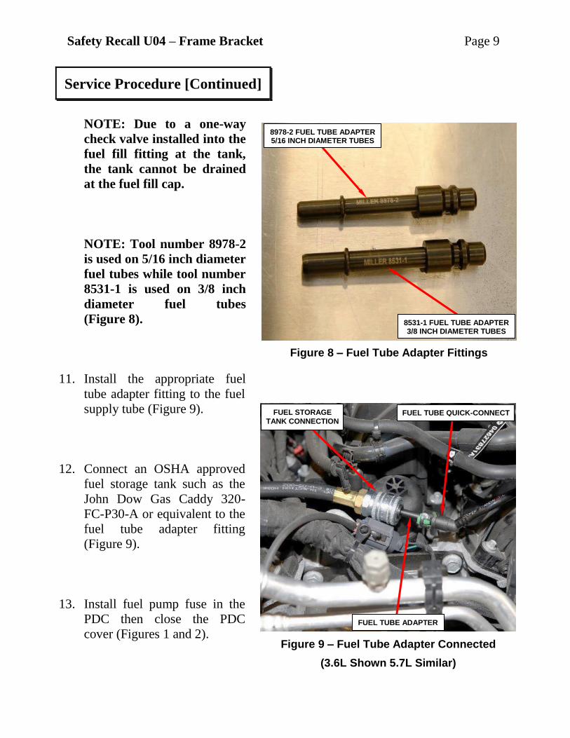
NOTE: Due to a one-way
check valve installed into the
fuel fill fitting at the tank,
the tank cannot be drained
at the fuel fill cap.
NOTE: Tool number 8978-2
is used on 5/16 inch diameter
fuel tubes while tool number
8531-1 is used on 3/8 inch
diameter fuel tubes
(Figure 8).
11. Install the appropriate fuel
tube adapter fitting to the fuel
supply tube (Figure 9).
12. Connect an OSHA approved
fuel storage tank such as the
John Dow Gas Caddy 320-
FC-P30-A or equivalent to the
fuel tube adapter fitting
(Figure 9).
13. Install fuel pump fuse in the
PDC then close the PDC
cover (Figures 1 and 2).
Service Procedure [Continued]
Figure 8 – Fuel Tube Adapter Fittings
Figure 9 – Fuel Tube Adapter Connected
(3.6L Shown 5.7L Similar)
FUEL TUBE QUICK-CONNECT
8978-2 FUEL TUBE ADAPTER 5/16 INCH DIAMETER TUBES
8531-1 FUEL TUBE ADAPTER 3/8 INCH DIAMETER TUBES
FUEL TUBE ADAPTER
FUEL STORAGE
TANK CONNECTION

Safety Recall U04 – Frame Bracket Page 10
14. Install a battery charger and verify that the charging rate provides 13.2 to 13.5
volts. Do not allow the charger to time out during the fuel evacuation process.
Set the battery charger timer (if so equipped) to continuous charge.
15. Connect the wiTECH micro pod II to the vehicle data link connector.
16. Place the ignition in the “RUN” position.
17. Open the wiTECH 2.0 website.
18. Enter your “User id” your “Password” and your “Dealer Code”, then select
“Finish” at the bottom of the screen.
19. From the “Vehicle Selection” screen, select the appropriate vehicle.
20. From the “Action Items” screen, select the “Topology” tab.
21. From the “Topology” screen, click on the “PCM” icon.
22. From the “PCM” screen, select the “Actuators” tab.
23. From the “Actuators” screen, select “Fuel Pump Relay Control State
Actuator Start Options”. Select “ON” and click “Start” to begin fuel tank
evacuation.
24. Once fuel tank is drained, turn the ignition to the “OFF” position.
25. Remove the battery charger from the vehicle.
26. Remove the fuel tube adapter fitting from the fuel supply tube and plug the fuel
supply tube with a shipping cap to prevent spillage.
Service Procedure [Continued]

Safety Recall U04 – Frame Bracket Page 11
27. Disconnect and isolate the
negative battery cable by
removing only the captive
nut securing the terminal
end to the post (Figure 10)
NOTE: If equipped with
an Intelligent Battery
Sensor (IBS), disconnect
the IBS connector first
before disconnecting the
negative battery cable.
28. Raise and support the
vehicle.
29. Disconnect the electrical
connector from the
Evaporative System
Integrity Monitor (ESIM)
switch (Figure 11).
F Figure 11 – EVAP Canister ESIM Switch
Service Procedure [Continued]
Figure 10 – Negative Battery Cable
VEHICLE BATTERY NEGATIVE BATTERY TERMINAL
INTELLIGENT BATTERY SENSOR
EVAP CANISTER ESIM SWITCH FUEL TANK
EVAP VAPOR HOSE ESIM ELECTRICAL CONNECTOR

Safety Recall U04 – Frame Bracket Page 12
30. Disconnect the vapor hose from the ESIM switch (Figure 11).
31. Disconnect the EVAP vent tube quick-connect fitting at the rear of the fuel tank
(Figure 12).
32. Disconnect the EVAP vent
tube quick-connect fitting at
the front of fuel tank
(Figure 13).
33. Using a suitable hydraulic
jack with a fuel tank
adapter, support the fuel
tank.
34. Remove the two fuel tank
support strap retaining nuts
and remove both fuel tank
support straps.
35. Carefully lower the fuel tank a few inches and disconnect the fuel pump module
electrical connector.
36. Disconnect the fuel line quick-connect fitting at the fuel pump module.
37. Loosen the fuel fill hose clamp at fuel tank and disconnect fill hose from fuel
tank.
38. Lower the fuel tank and move it away from under the vehicle.
Service Procedure (Continued)
Figure 12 – Evaporative Tube
Figure 13 – Vent Tube Quick Connect
REAR VENT TUBE
FRONT VENT TUBE CONNECTION
Safety Recall U04 – Frame Bracket Page 13
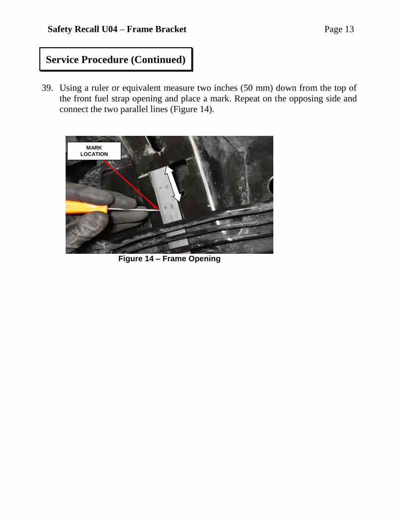
39. Using a ruler or equivalent measure two inches (50 mm) down from the top of
the front fuel strap opening and place a mark. Repeat on the opposing side and
connect the two parallel lines (Figure 14).
Service Procedure (Continued)
Figure 14 – Frame Opening
MARK
LOCATION
Safety Recall U04 – Frame Bracket Page 14
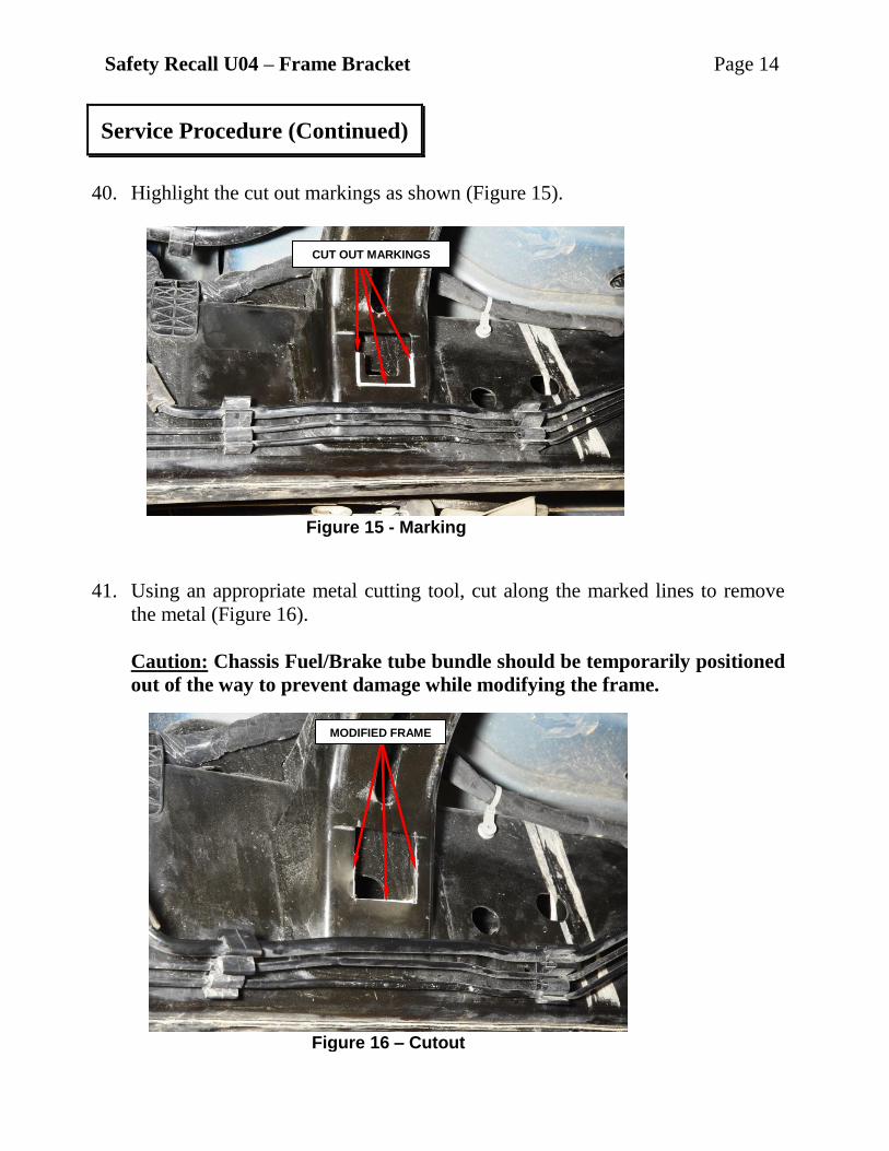
40. Highlight the cut out markings as shown (Figure 15).
41. Using an appropriate metal cutting tool, cut along the marked lines to remove
the metal (Figure 16).
Caution: Chassis Fuel/Brake tube bundle should be temporarily positioned
out of the way to prevent damage while modifying the frame.
Service Procedure (Continued)
Figure 15 - Marking
Figure 16 – Cutout
CUT OUT MARKINGS
MODIFIED FRAME
Safety Recall U04 – Frame Bracket Page 15
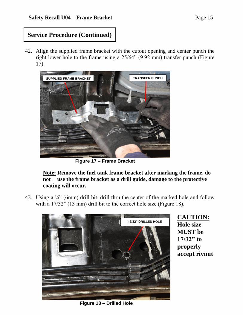
42. Align the supplied frame bracket with the cutout opening and center punch the
right lower hole to the frame using a 25/64” (9.92 mm) transfer punch (Figure
17).
Note: Remove the fuel tank frame bracket after marking the frame, do
not use the frame bracket as a drill guide, damage to the protective
coating will occur.
43. Using a ¼” (6mm) drill bit, drill thru the center of the marked hole and follow
with a 17/32” (13 mm) drill bit to the correct hole size (Figure 18).
CAUTION:
Hole size
MUST be
17/32” to
properly
accept rivnut
Service Procedure (Continued)
Figure 17 – Frame Bracket
Figure 18 – Drilled Hole
TRANSFER PUNCH SUPPLIED FRAME BRACKET
17/32” DRILLED HOLE

Safety Recall U04 – Frame Bracket Page 16
44. Using the installation tool WTT106001A or equivalent install the rivnut onto
to the tool then into drilled out hole and use an wrench to hold the nut and a
wrench to turn the bolt fully until it will no longer turn (Figure 19).
45. Align and install the NEW frame bracket using the provided bolt to temporary
hold the bracket in place (Figure 20).
Service Procedure (Continued)
Figure 19 – Rivnut Install
Figure 20 – Frame Bracket
RIVNUT INSTALLATION TOOL
Safety Recall U04 – Frame Bracket Page 17
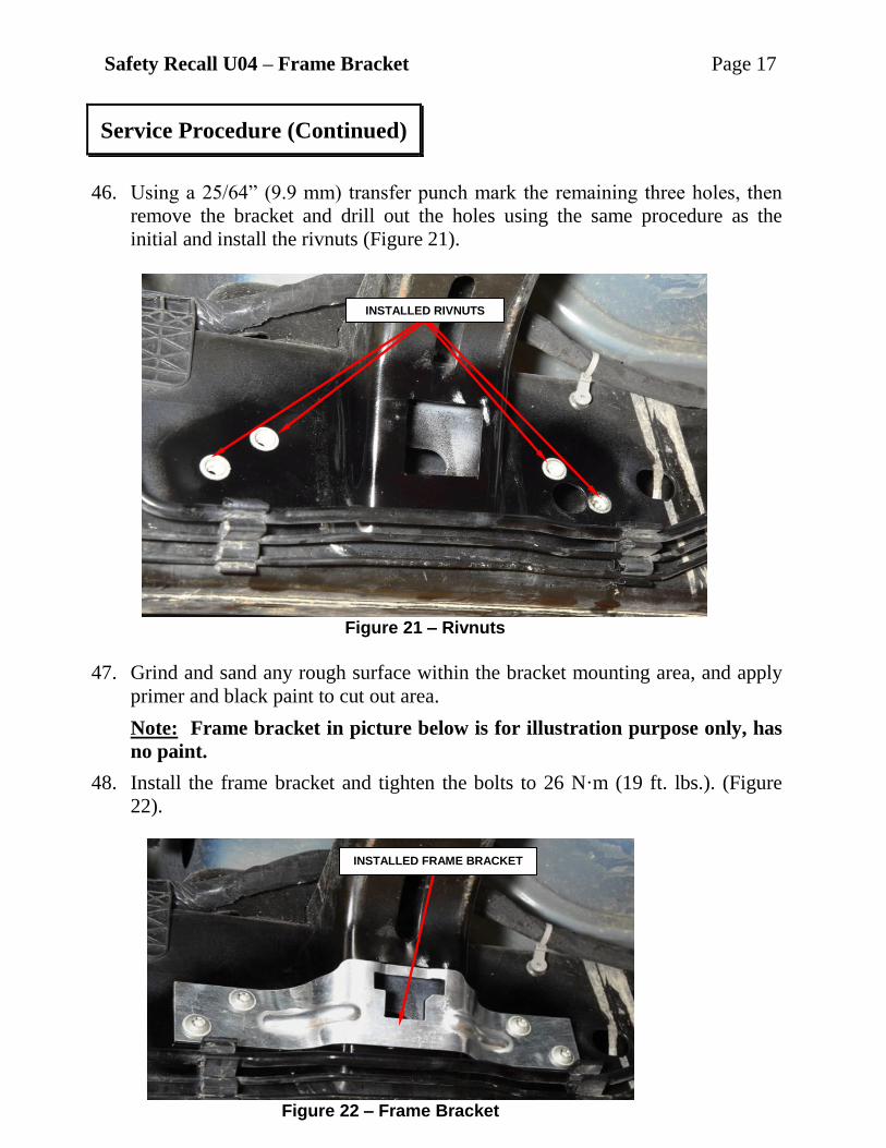
46. Using a 25/64” (9.9 mm) transfer punch mark the remaining three holes, then
remove the bracket and drill out the holes using the same procedure as the
initial and install the rivnuts (Figure 21).
47. Grind and sand any rough surface within the bracket mounting area, and apply
primer and black paint to cut out area.
Note: Frame bracket in picture below is for illustration purpose only, has
no paint.
48. Install the frame bracket and tighten the bolts to 26 N·m (19 ft. lbs.). (Figure
22).
Service Procedure (Continued)
Figure 21 – Rivnuts
Figure 22 – Frame Bracket
INSTALLED RIVNUTS
INSTALLED FRAME BRACKET

Safety Recall U04 – Frame Bracket Page 18
49. Align the gas tank to the underbody and raise leaving room to make the
connections at the top of the fuel tank.
50. Connect the fuel supply line to the fuel pump module.
51. Connect the electrical connector to the fuel pump module.
52. Connect the fuel fill hose and securely tighten clamp.
53. Raise the fuel tank until snug to the body.
54. If the old fuel tank strap was disconnected from the original frame bracket,
replace the front and rear fuel tanks straps with NEW fuel tank straps.
55. Install the NEW strap nuts and tighten to 41 N·m) (30 ft. lbs.).
56. Remove the hydraulic jack.
57. Connect the electrical connector to the Evaporative System Integrity Monitor
(ESIM) switch.
58. Connect the EVAP vapor hose to the ESIM.
59. Connect the quick-connect fitting at the rear of the fuel tank.
60. Connect the quick-connect fitting at the front of the fuel tank.
61. Lower vehicle, reconnect the ground cable.
62. 3.6L engines only, perform the following steps to install the air duct system:
a. Lubricate the two rubber ball stud sockets on the resonator.
b. Install the resonator to the throttle body inlet. Push the resonator down onto
the two locating ball studs until the rubber mount sockets are fully seated.
(Figure 4).
c. Tighten the band clamp to 4 N·m (35 in. lbs.) (Figure 3).
d. Connect the IAT sensor electrical connector (Figure 3).
Service Procedure (Continued)
Safety Recall U04 – Frame Bracket Page 19
e. Align the air cleaner cover to the lower air cleaner cover.
f. Secure the air cleaner cover latches (Figure 4).
63. 5.7L engines only, perform the following steps to install the air duct system:
NOTE: The engine cover front grommets are a ball stud type mount
and the rear grommets are a sliding peg design.
a. Slightly tilt the rear of the engine cover and slide the rear engine cover pegs
into the grommets on the rear of the intake manifold until the cover stops
(Figure 5).
NOTE: While installing the engine cover the front ball studs will make a
popping or suction sound as the ball studs are inserted into the front
grommets.
b. Lower the front of the engine cover and line up the front ball studs with the
grommets on the front of the intake manifold. Push the engine cover down
onto the two locating ball studs until the rubber mount sockets are fully
seated (Figure 5).
c. Lightly lift the front of the engine cover to insure the front ball studs are
seated into the front grommets correctly. Check the rear of the engine cover
to verify that the pegs are located in the grommets.
d. Install the clean air tube onto the air cleaner housing and the throttle body.
(Figure 5).
e. Tighten the band clamps at the air cleaner housing and throttle body to
4 N·m (35 in. lbs.) (Figure 5).
f. Connect the IAT sensor electrical connector (Figure 5).
64. Connect the negative battery cable and tighten nut to 5 N·m (45 in. lbs.)
65. If equipped, connect the Intelligent Battery Sensor (IBS) (Figure 10).
Service Procedure [Continued]
Safety Recall U04 – Frame Bracket Page 20
66. Fill the fuel tank and install the fuel cap.
67. Start the engine and check for leak at the fuel tank connections.
68. Turn the ignition to the “OFF” position.
NOTE: One or more Diagnostic Trouble Codes (DTCs) may have been
stored in the PCM memory due to disconnecting fuel pump module circuit.
A diagnostic scan tool must be used to erase a DTC.
69. Install a battery charger and verify that the charging rate provides 13.2 to 13.5
volts. Set the battery charger timer (if so equipped) to continuous charge.
70. Connect the wiTECH micro pod II to the vehicle data link connector
71. Place the ignition in the “RUN” position.
72. Open the wiTECH 2.0 website.
73. Enter your “User id” your “Password” and your “Dealer Code”, then select
“Finish” at the bottom of the screen.
74. From the “Vehicle Selection” screen, select the appropriate vehicle.
75. Select the “All DTCs” tab, then click “Clear All DTCs”, click “Continue” and
then select “Close”.
76. Turn the ignition to the “OFF” position and then remove the wiTECH micro
pod II device from the vehicle.
77. Remove the battery charger from the vehicle then close the hood.
78. Return vehicle to the customer.
Service Procedure [Continued]

Safety Recall U04 – Frame Bracket Page 21
Claims for vehicles that have been serviced must be submitted on the
DealerCONNECT Claim Entry Screen located on the Service tab. Claims paid
will be used by FCA to record recall service completions and provide dealer
payments.
Use the following labor operation number and time allowance:
Labor Operation Time
Number Allowance
Install Fuel Tank Strap Mounting Bracket 13-U0-41-82 2.1 hours
NOTE: See the Warranty Administration Manual, Recall Claim Processing
Section, for complete recall claim processing instructions.
To view this notification on DealerCONNECT, select “Global Recall System” on
the Service tab, then click on the description of this notification.
All involved vehicle owners known to FCA are being notified of the service
requirement by first class mail. They are requested to schedule appointments for this
service with their dealers. A generic copy of the owner letter is attached.
Completion Reporting and Reimbursement
Dealer Notification
Owner Notification and Service Scheduling
Safety Recall U04 – Frame Bracket Page 22
All involved vehicles have been entered into the DealerCONNECT Global Recall
System (GRS) and Vehicle Information Plus (VIP) for dealer inquiry as needed.
GRS provides involved dealers with an updated VIN list of their incomplete
vehicles. The owner’s name, address and phone number are listed if known.
Completed vehicles are removed from GRS within several days of repair claim
submission.
To use this system, click on the “Service” tab and then click on “Global Recall
System.” Your dealer’s VIN list for each recall displayed can be sorted by: those
vehicles that were unsold at recall launch, those with a phone number, city, zip
code, or VIN sequence.
Dealers must perform this repair on all unsold vehicles before retail delivery.
Dealers should also use the VIN list to follow up with all owners to schedule
appointments for this repair.
Recall VIN lists may contain confidential, restricted owner name and address information that
was obtained from the Department of Motor Vehicles of various states. Use of this information
is permitted for this recall only and is strictly prohibited from all other use.
If you have any questions or need assistance in completing this action, please
contact your Service and Parts District Manager.
Customer Services / Field Operations
FCA US LLC
Vehicle Lists, Global Recall System, VIP and Dealer Follow Up
Additional Information

This notice applies to your vehicle,
U04/NHTSA 18V-160
YOUR SCHEDULING OPTIONS
1. RECOMMENDED OPTIONCall your authorized Chrysler /
Dodge / Jeep® / RAM / Dealership
2. Call the FCA Recall Assistance
Center at 1-800-853-1403. An
agent can confirm part availability
and help schedule an appointment
3. Visit recalls.mopar.com, scan the
QR code below, or download the
Mopar Owner’s Companion App.
Get access to recall notifications, locate
your nearest dealer, and more through
this website or Mopar Owner’s
Companion App. You will be asked to
provide your Vehicle Identification
Number (VIN) to protect and verify
your identity. The last eight characters
of your VIN are provided above.
DEALERSHIP INSTRUCTIONS
Please reference Safety Recall U04.
IMPORTANT SAFETY RECALLFrame Bracket
Dear [Name],
This notice is sent to you in accordance with the National Traffic and Motor Vehicle Safety Act.
FCA has decided that a defect, which relates to motor vehicle safety, exists in certain [2009 –
2012 (DS) RAM 1500 Pickup] vehicles.
It is extremely important to take steps now to repair your vehicle to ensure the safety of you and
your passengers.
WHY DOES MY VEHICLE NEED REPAIRS?
The front fuel tank strap on your truck [1] may become loose due to the frame bracket corrosion.
With the front fuel tank strap detached, the rear strap primarily secures the fuel tank, however,
the front of the fuel tank may be allowed to lower several inches. The vehicle driver may notice
a noise, the strap or fuel tank hanging down, frame corrosion, or may be informed during an oil
change/state inspection. Detachment of the front fuel tank strap could potentially allow the front
of the fuel tank to make contact with the ground, increasing the risk of a fuel leak. A fuel leak
in the presence of an ignition source could result in a fire.
HOW DO I RESOLVE THIS IMPORTANT SAFETY ISSUE?
FCA will repair your vehicle [2] free of charge (parts and labor). To do this, your dealer will
install a fuel tank strap reinforcement bracket. If the fuel tank strap is found to be disconnected
from the original frame bracket, the front and rear fuel tanks straps as well as the locking nuts,
will be replaced. In addition, your dealer will require your vehicle for proper check-in,
preparation, and checkout during your visit. Your time is important to us; please be aware that
these steps may require more time. The estimated repair time is two and half-hours. We
recommend that you schedule a service appointment to minimize your inconvenience. Please
bring this letter with you to your dealership.
TO SCHEDULE YOUR FREE REPAIR CALL 1-800-853-1403
OR YOUR CHRYSLER, DODGE, JEEP OR RAM DEALER TODAY
WHAT IF I ALREADY PAID TO HAVE THIS REPAIR COMPLETED?
If you have already experienced this specific condition and have paid to have it repaired, you
may visit www.fcarecallreimbursement.com to submit your reimbursement request online. [3]
Once we receive and verify the required documents, reimbursement will be sent to you within
60 days. If you have had previous repairs performed and/or already received reimbursement,
you may still need to have the recall repair performed.
We apologize for any inconvenience, but are sincerely concerned about your safety. Thank you
for your attention to this important matter.
Customer Assistance/Field Operations
Fiat Chrysler Automobiles US LLC
[Model Year and Model]VIN XXXXXXXXXXXXXXXXX
LOGO
VEHICLE PICTURE
QR Code
[1] If you no longer own this vehicle, please help us update our records. Call the FCA Recall Assistance Center at 1-800-853-1403 to update your information.
[2] If your dealer fails or is unable to remedy this defect without charge and within a reasonable time, you may submit a written complaint to the Administrator, National HighwayTraffic Safety Administration, 1200 New Jersey Ave., S.E., Washington, DC 20590, or you can call the toll-free Vehicle Safety Hotline at 1-888-327-4236 (TTY 1-800-424-9153), or go to safercar.gov.
[3] You can also mail in your original receipts and proof of payment to the following address for reimbursement consideration: FCA Customer Assistance, P.O. Box 21-8004,Auburn Hills, MI 48321-8007, Attention: Recall Reimbursement.
Note to lessors receiving this recall notice: Federal regulation requires that you forward this recall notice to the lessee within 10 days.
Mr. Mrs. Customer
1234 Main Street
Hometown, MI 48371