may 2004stereo1 introduction to computer vision cs / ece 181b tuesday, may 11, 2004 multiple view...
Post on 21-Dec-2015
219 views
TRANSCRIPT

May 2004 Stereo 1
Introduction to Computer Vision
CS / ECE 181B
Tuesday, May 11, 2004
Multiple view geometry and stereo Handout #6 available (check with Isabelle)
Ack: M. Turk and M. Pollefeys

May 2004 Stereo 2
Midterm

May 2004 Stereo 3
Seeing in 3D
• Humans can perceive depth, shape, etc. – 3D properties of the world– How do we do it?
• We use many cues– Oculomotor convergence/divergence
– Accomodation (changing focus)
– Motion parallax (changing viewpoint)
– Monocular depth cues Occlusion, perspective, texture gradients, shading, size
– Binocular disparity (stereo)
• How can computers perceive depth?

May 2004 Stereo 4

May 2004 Stereo 5

May 2004 Stereo 6
Multiple views and depth

May 2004 Stereo 7
Why multiple views?
• A camera projects the 3D world into 2D images
• This is not always a problem – humans can figure out a lot from a 2D view!

May 2004 Stereo 8
Why multiple views?
• But precise 3D information (distance, depth, shape, curvature, etc.) is difficult or impossible to obtain from a single view
• In order to measure distances, sizes, angles, etc. we need multiple views (and calibrated cameras!)– Monocular binocular trinocular…
C1
C2
C 3

May 2004 Stereo 9
Multiple view geometry
C1
C2
C 3
• Two big questions for multiple view geometry problems:– Which are possible?
– Which are most likely?
• There are many possible configurations of scene points that could have created corresponding points in multiple views

May 2004 Stereo 10
Questions
• Correspondence geometry: Given an image point x in the first view, how does this constrain the position of the corresponding
point x’ in the second image?
• Camera geometry (motion): Given a set of corresponding image points {xi ↔x’i}, i=1,…,n, what are the cameras P and P’ for the two views?
• Scene geometry (structure): Given corresponding image points xi ↔x’i and cameras P, P’, what is the position of (their pre-image) X in space?
M. Pollefeys

May 2004 Stereo 11
Two-view geometry
C1C2
Epipolar line
Not necessarily along a row of the image
p
• The epipolar geometry is defined by the origins of the camera coordinate frames, the scene point P, and the locations of the image planes
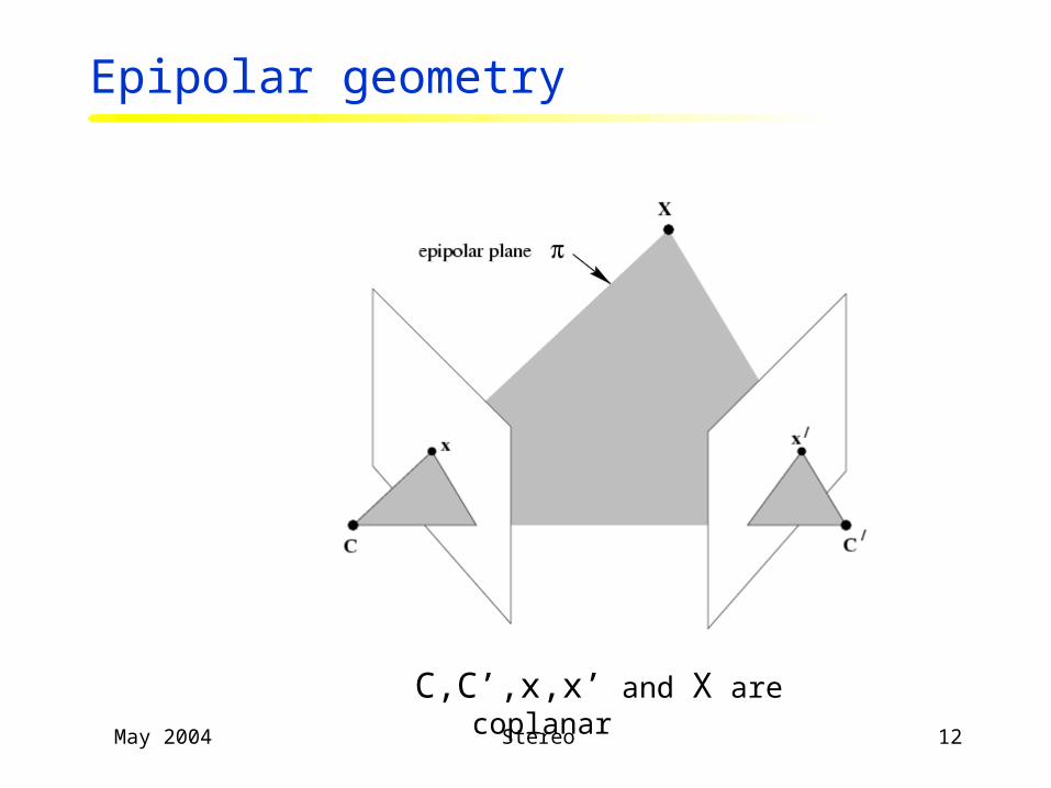
May 2004 Stereo 12
C,C’,x,x’ and X are coplanar
Epipolar geometry
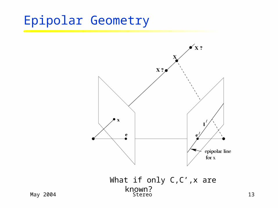
May 2004 Stereo 13
What if only C,C’,x are known?
Epipolar Geometry

May 2004 Stereo 14
All points on project on l and l’
Epipolar Geometry

May 2004 Stereo 15
Family of planes and lines l and l’ Intersection in e and e’
Epipolar Geometry
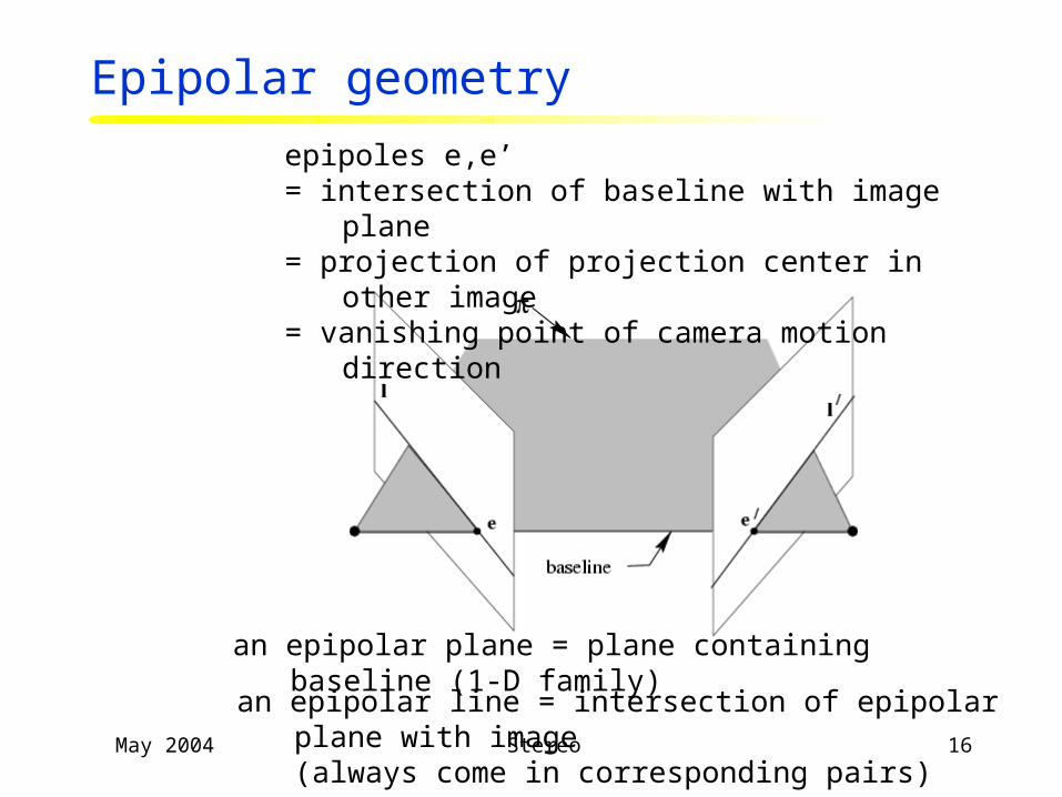
May 2004 Stereo 16
epipoles e,e’= intersection of baseline with image plane = projection of projection center in other image= vanishing point of camera motion direction
an epipolar plane = plane containing baseline (1-D family)
an epipolar line = intersection of epipolar plane with image(always come in corresponding pairs)
Epipolar geometry

May 2004 Stereo 17
Epipolar geometry
• Epipolar Plane
• Epipoles
• Epipolar Lines
• Baseline
C1 C2

May 2004 Stereo 18
Epipolar constraint
• Potential matches for p have to lie on the corresponding epipolar line l’
• Potential matches for p’ have to lie on the corresponding epipolar line l

May 2004 Stereo 19
Example: converging cameras

May 2004 Stereo 20
Example: motion parallel with image plane

May 2004 Stereo 21
Example: forward motion
e
e’

May 2004 Stereo 22
Trinocular epipolar constraint
May 2004 Stereo 23
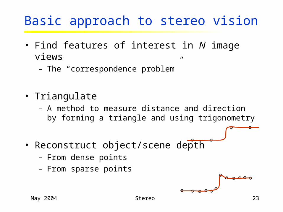
Basic approach to stereo vision
• Find features of interest in N image views– The “correspondence problem”
• Triangulate– A method to measure distance and direction by forming a triangle
and using trigonometry
• Reconstruct object/scene depth– From dense points
– From sparse points
May 2004 Stereo 24
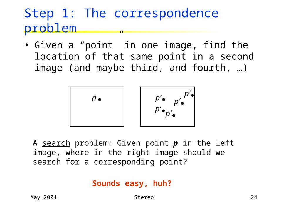
Step 1: The correspondence problem
• Given a “point” in one image, find the location of that same point in a second image (and maybe third, and fourth, …)
p
A search problem: Given point p in the left image, where in the right image should we search for a corresponding point?
p’ p’p’
p’
p’
Sounds easy, huh?

May 2004 Stereo 25
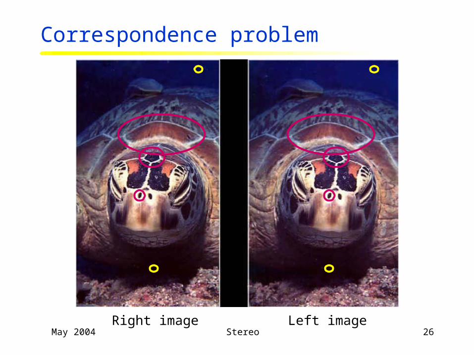
Correspondence problem
Right imageLeft image
• What is a point?
• How do we compare points in different images? (Similarity measure)
May 2004 Stereo 26
Correspondence problem
Left imageRight image
May 2004 Stereo 27
The correspondence problem
• A classically difficult problem in computer vision– Is every point visible in both images?
– Do we match points or regions or …?
– Are corresponding (L-R) image regions similar?
• Correspondence is easiest when the depth is large compared with the camera baseline distance– Because the cameras then have about the same viewpoint
– But…
• Two classes of stereo correspondence algorithms:– Feature based (sparse) – corners, edges, lines, …
– Correlation based (dense) How large a window of support to use?

May 2004 Stereo 28
Multiple views
• What do you need to know in order to calculate the depth (or location) of the point that causes p and p' ?
C1 C2
p p
• Values of p = (u, v) and p = (u, v)
• Locations of C1 and C2 (full extrinsic parameters)
– Rigid transformation between C1 and C2
• Intrinsic parameters of C1 and C2

May 2004 Stereo 29
Duality: Calibration and stereo
• Given calibrated cameras, we can find depth of points
• Given corresponding points, we can calibrate the cameras
C1
C2
C1
C2

May 2004 Stereo 30
Example: Extrinsic parameters from 3 points
C1
C2
1 known point
2 known points
3 known points
In this case, we know the point correspondences and the point distances.
If we only know the correspondences, we’ll need at least five points

May 2004 Stereo 31
The geometry of multiple views
• Epipolar Geometry– The Essential Matrix
– The Fundamental Matrix
• The Trifocal Tensor
• The Quadrifocal Tensor
Baseline
c c’

May 2004 Stereo 32
Epipolar geometry
• Epipolar Plane
• Epipoles
• Epipolar Lines
• Baseline
C1 C2

May 2004 Stereo 33
Epipolar constraint
• Potential matches for p have to lie on the corresponding epipolar line l’
• Potential matches for p’ have to lie on the corresponding epipolar line l

May 2004 Stereo 34
Epipolar lines example

May 2004 Stereo 35
Matrix form of cross product
• The cross product of two vectors is a third vector, perpendicular to the others (right hand rule)
⎥⎥
⎦
⎤
⎢⎢
⎣
⎡
−−−
=×1221
3113
2332
babababababa
ba baa
aaaa
⎥⎥
⎦
⎤
⎢⎢
⎣
⎡
−−
−=
00
0
12
13
23
0)(
0)(
=×⋅=×⋅
babbaa
[ ]ba×=

May 2004 Stereo 36
p p
Case 1: Calibrated camera
O O
P
OP
Op
O P
O p
OO
Op · (OO O p ) = ?Op · (OO O p ) = 0
[ R t ] – rigid trans. from O to Op · (t Rp ) = 0
This can be written in matrix form as:
pT E p = 0

May 2004 Stereo 37
Essential Matrix
p p
O O
P
OP
Op
O P
O p
OO
pT E p = 0[ ] R
tttt
ttRtE
xy
xz
yz
⎟⎟⎟
⎠
⎞
⎜⎜⎜
⎝
⎛
−−
−== ×
00
0p · (t Rp ) = 0
E - Essential Matrix

May 2004 Stereo 38
The Essential Matrix
• E describes the transformation between camera coordinate frames
• E has five degrees of freedom– Defined up to a scale factor, since
pT E p = 0
• Why only five?– A rigid transformation has six degrees of freedom
• 3 rotation parameters, 2 translation direction parameters– Why only translation direction?

May 2004 Stereo 39

May 2004 Stereo 40
“Up to a scale factor”
• This is always the case with camera calibration and stereo– Shrink everything 10x and it all looks the same!
• Typically there is something we know that we can use to specify the scale factor– E.g., the baseline, the size of an object, the depth of a point/plane

May 2004 Stereo 41
Camera calibration from E
• With five unknowns, theoretically we can recover the essential matrix E by writing pT E p = 0 for five corresponding pairs of points– 5 equations and 5 unknowns
– We don’t need to know anything about the points (e.g., their depth), only that they project to pi and pi
– There are, however, limitations…
• This is used for camera calibration (extrinsic parameters)C1 C2

May 2004 Stereo 42
Case 2: Uncalibrated camera
• Intrinsic parameters not known
0ˆˆ =pEpT
0
0)()(
0)()(1
21
12
11
=
=
=−−
−−
pFp
pKEKp
pKEpK
T
TT
T
pKp ˆ1=
pKp = ˆ2
121−−= KEKF T
Fundamental Matrix
⎥⎥⎥⎥
⎦
⎤
⎢⎢⎢⎢
⎣
⎡ −
=
100sin
0
cot
0
0
v
u
Kθ
βθαα
Points in the normalized image plane

May 2004 Stereo 43
geometric derivation
xHx' ∂=
x'e'l' ×= [ ] FxxHe' ∂ == ×
mapping from 2-D to 1-D family (rank 2)
Fundamental Matrix F

May 2004 Stereo 44
The Fundamental Matrix
• F has seven independent parameters
• A simple, linear technique to recover F from corresponding point locations is the “eight point algorithm”
• From F, we can recover the epipolar geometry of the cameras– Not saying how…
• This is called weak calibration

May 2004 Stereo 45
The eight-point algorithm
0=pFpT
Invert and solve for F

May 2004 Stereo 46
Least squares approach
Minimize:
under the constraint |F|2 = 1
If n > 8

May 2004 Stereo 47
Nonlinear least-squares approach
Minimize
with respect to the coefficients of F
Point in image 1
Epipolar line in image 1 caused by p
Nonlinear – initialize it from the results of the eight-point algorithm

May 2004 Stereo 48
Least squares 8-point algorithm Hartley’s normalized 8-point alg.

May 2004 Stereo 49
Stereo vision (Stereopsis)

May 2004 Stereo 50
I1 I2 I10

May 2004 Stereo 51
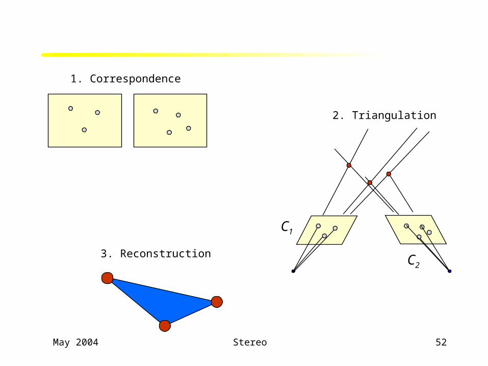
Basic approach to stereo vision
• Find features of interest in N image views– The “correspondence problem”
• Triangulate– A method to measure distance and direction by forming a triangle
and using trigonometry
• Reconstruct object/scene depth– From dense points
– From sparse points
May 2004 Stereo 52
1. Correspondence
C1
C2
2. Triangulation
3. Reconstruction

May 2004 Stereo 53
Problem…
• Measurement error causes point Q to be seen at location p rather than the correct location q– A least squares method will triangulate to point P

May 2004 Stereo 54
Correspondence
• Knowing the epipolar geometry certainly helps– Look on (and near) the epipolar line
• But correspondence is hard!
• Two approaches– Try to improve correspondence matching
– Try to avoid correspondence matching
C1
C2
p
May 2004 Stereo 55
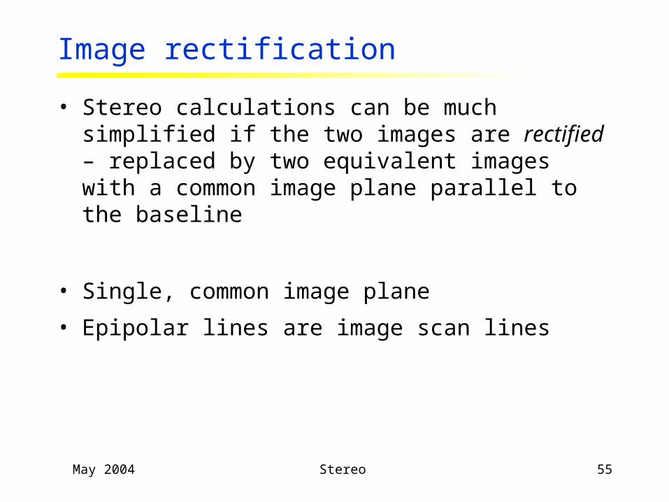
Image rectification
• Stereo calculations can be much simplified if the two images are rectified – replaced by two equivalent images with a common image plane parallel to the baseline
• Single, common image plane
• Epipolar lines are image scan lines

May 2004 Stereo 56
Rectification example

May 2004 Stereo 57
Correlation based stereo matching
Texture-mapped reconstructed surface
May 2004 Stereo 58
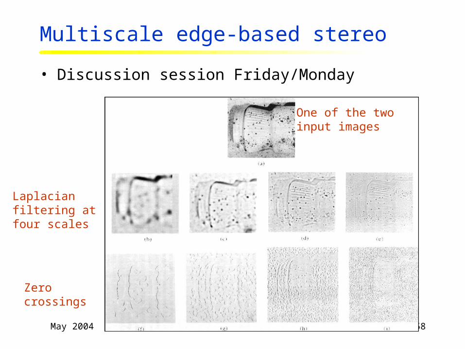
Multiscale edge-based stereo
• Discussion session Friday/Monday
One of the twoinput images
Laplacian filtering at four scales
Zero crossings

May 2004 Stereo 59
Depth map
Reconstructed surface