maxum edition ii process gas chromatograph -...
TRANSCRIPT

Siemens Applied Automation
Maxum edition II Process Gas Chromatograph
November 2001 Installation Manual 2000595-001

Copyright Notice
2001 by Siemens Applied Automation Bartlesville, Oklahoma, 74003, U.S.A. All rights reserved.
This publication is for information only. The contents are subject to change without notice and should not be construed as a commitment, representation, warranty, or guarantee of any method, product, or device by Siemens Applied Automation.
Reproduction or translation of any part of this publication beyond that permitted by Sections 107 and 109 of the United States Copyright Act without the written consent of the copyright owner is unlawful.
Inquiries regarding this manual should be addressed to:
Siemens Applied Automation Technical Communications 500 Highway 60 West Bartlesville, Oklahoma, 74003, U.S.A.
Trademarks
Maxum and Maxum edition II is a trademark of Siemens Applied Automation

Table of Contents
Technical Support iii Safety Practices & Precautions v
Introduction 1 Chapter 1: Overview 1 Site Considerations 2 Maxum II Specifications 3 Maxum II Outline Drawing 6
Installation 7 Chapter 2: Receiving a Non Crated Analyzer 9 Receiving a Crated Analyzer 10 Mounting the Analyzer 11 CE Installation Requirements 14 Installing Primary AC Power 17 Utility Gas Supply Installation 23 Sampling System Installation 27 Analyzer Connections 31 Preliminary Maxum II Startup Procedures 33 Maxum II Startup Procedure Using the Workstation Software 40 Assigning IP & Sub Network Mask Addresses 44 Requesting Start-Up Assistance 45
2000595-001 Table of Contents • i/ii


Technical Support
At Siemens Applied Automation we take pride in the on going support we provide our customers. When you purchase a product, you receive a detailed manual that should answer your questions; however, our techni-cal support service provides a special “hot” line as an added source of information.
Getting Help
If you require assistance call:
Inside Oklahoma: (918) 662-7430 Outside Oklahoma: (800) 448-8224 Internationally: 001-918-662-7430
Before calling Siemens Applied Automation Customer Service for instal-lation technical assistance, maintenance personnel should have the unit serial number and a detailed description of the problem for presentation to the customer service representative.
Before You Call
Indicate the encountered installation problem and provide any other in-formation that will aid the customer service representative in correcting the problem.
2000595-001 Technical Support • iii


Safety Practices and Precautions
This product has been designed and tested in accordance with IEC Pub-lication 1010-1, Safety Requirements for Electronic Measuring Appara-tus, and has been supplied in a safe condition. This manual contains information and warnings, which have to be followed by the user to en-sure safe operation and to retain the product in a safe condition.
Safety First
WARNING statements identify conditions or practices that could result in personal injury or loss of life.
Terms in This Manual
CAUTION statements identify conditions or practices that could result in damage to the equipment or other property.
DANGER indicates a personal injury hazard immediately accessible as one reads the markings.
Terms as Marked on Equipment
CAUTION indicates a personal injury hazard not immediately accessible as one reads the markings, or a hazard to property, including the equip-ment itself.
This symbol indicates where applicable cautionary or other information is to be found.
Symbols in This Manual
DANGER - High voltage
Protective ground (earth) terminal
ATTENTION - Refer to Manual
Symbols Marked on Equipment
2000595-001 Safety Practices and Precautions • v

Safety Practices and Precautions, Continued
Before switching on the power, check that the operating voltage listed on the equipment agrees with the available line voltage. Ensure that the power supply switch is to the correct input voltage.
Correct Operating Voltage
Any interruption of the grounding conductor inside or outside the equip-ment or loose connection of the grounding conductor can result in a dan-gerous unit. Intentional interruption of the grounding conductor is not permitted.
Danger Arising from Loss of Ground
If it is determined that the equipment cannot be operated safely, it should be taken out of operation and secured against unintentional usage.
Safe Equipment
To avoid fire hazard, use only a fuse of the correct type, voltage rating and current rating as specified in the parts list for your product. Use of repaired fuses or short-circuiting of the fuse switch is not permitted.
Use the Proper Fuse
DO NOT open the equipment to perform any adjustment, measure-ments, maintenance, parts replacement or repairs until all power sup-plies have been disconnected.
Safety Guidelines
Only a properly trained technician should work on any equipment with power still applied.
When opening covers or removing parts, exercise extreme care "live parts or connections can be exposed".
vi • Safety Practices and Precautions 2000595-001

Chapter 1
Introduction
Overview
Description This manual provides instructions for installation of the Maxum edition II Process Gas Chromatograph hereinafter referred to by its’ full name or as the Maxum II. After completing the instructions in this manual the Maxum II will be ready for startup. To ensure a safe and trouble free in-stallation follow all instructions and associated advisories in this manual.
Other Installation Manuals
• Advance Network Gateway Unit • Advance DataNET Hub Unit • Advance Network Access Unit • Advance CAN Extension Unit • Advance Maxum edition II Automatic Purge Unit
Chapter Highlights Topic Page
Site Considerations 2
Maxum II Specifications 3
Maxum II Outline Drawing 6
2000595-001 Introduction • 1

Site Considerations
To protect the Maxum II Gas Chromatograph from the elements it should be located in an analyzer house or a similar protected enclosure; see Figure 1-1. The air temperature around the analyzer should be main-tained between 0°F (-18°C) and 120°F (49°C).
Description
The analyzer house should be located as close as possible to where the sample is to be obtained to minimize the sample transit time. It is prefer-able that this distance be less than 100-feet (30 m).
Location
The analyzer house must be large enough to allow ample access for in-stalling, operating, and maintaining the analyzer. The concrete slab for the analyzer house should be large enough to accommodate gas cylin-ders located on the outside. Make sure a cylinder rack or chain guard is provided to secure the cylinders.
Space inside for the analyzer must be at least 90 inches high by 50 inches wide by 40 inches deep (229 cm high by 127 cm wide by 102 cm deep). The height may be somewhat less if there is no sampling system cabinet or panel beneath the analyzer. Refer to Maxum II Outline Draw-ing on page 6.
Alternately, the analyzer can be installed on a portable stand. If Siemens Applied Automation provides the portable stand (Part No. 2015548-001), the space required for the analyzer will be the same height and width as stated above, but the depth must be increased to 48 inches (122 cm).
Figure 1-1. Typical Analyzer House
To protect the Maxum edi-tion II Process Gas Chro-matograph from the ele-ments it should be located in an analyzer house or a simi-lar protected enclosure
2 • Introduction 2000595-001

Maxum II Specifications
Configuration Oven Options Single isothermal oven or split oven with 2 independent isothermal
zones Single or dual independent airless ovens. Dual version has two dis-tinct oven compartments for complete operating independence.
Detector Modules Thermal Conductivity, Flame Ionization, Flame Photometric, Helium Ionization, Electrolytic Conductivity or Electron Capture
Number of Detector Modules 1, 2, or 3 in any combination of detector module types for air bath oven 1 or 2 in any combination of detector module types for airless oven
Sample/Column Valves Diaphragm, diaphragm-plunger, and rotating or linear transport Valveless Option ‘Live’ Switching Columns Packed, micro-packed, or capillary Gas Supply Regulation Up to 8 electronic pressure controls and
up to 6 mechanical pressure controls
Performance Minimum Range (general)* Thermal Conductivity: 0-500 ppm
Flame Ionization: 0-1 ppm Repeatability (general)* ± 0.5% of full scale for full scale ranges from 2-100%;
± 1% of full scale for full scale ranges from 0.05-2%; ± 2% of full scale for full scale ranges from 50-500 ppm; ± 3% of full scale for full scale ranges from 5-50 ppm; ± 5% of full scale for full scale ranges from 0.5-5 ppm; (All values expressed at 2 times standard deviation.)
Cycle Time 15 sec to 3 hr (application dependent) Sensitivity* ± 0.5% of full scale Linearity* ± 2% of full scale Oven Temperature Range 40 to 440°F (5 to 225°C) Temperature Control ± 0.05°F (± 0.02°C) Ambient Temperature Effect None with electronic pressure control
Varying effect with mechanical pressure control* Vibration Effect Negligible Mean Time To Repair 1 hour Mean Time Between Failures* 3 years excluding consumables
Communication Options Serial Output RS232, RS485 Ethernet Standard 10BaseT Ethernet with RJ45 connectors DataNET Proprietary high speed TCP/IP communication network (redundant
pair cable) Data Hiway Proprietary serial communication network (redundant pair cable) *confirm with application
2000595-001 Introduction • 3

Maxum II Specifications, Continued
I/O Options Standard I/O 2 analog outputs; 4 digital outputs; (1 indicates system error, 3 are user
configurable); 4 digital inputs; 1 serial output Board Slots for Optional I/O 2 I/O Boards AO 8: 8 electrically isolated analog output channels
D IO: 4 digital inputs and 4 digital outputs A I/O: 2 digital inputs and 2 digital outputs, 2 analog inputs and 2 analog outputs
Digital Inputs Optocoupler with internal 12-24 Vdc power supply, switchable with floating contacts. Alternative: switchable with external 12-24 Vdc supply (floating relay contacts only), external power supply negative terminal connected to common for specific DI being used
Digital Outputs Floating double-throw contacts, maximum contact load rating 1 A at 30 Vdc. Diode shunt suppression should be used for inductive loads.
Analog Inputs -20 to +20 mA into 50 ohms or -10 to +10 V Rin = 1 M ohm, mutually isolated to 10 V
Analog Outputs 0/4 to 20 mA into 750 ohms max., common negative pole, galvanically separated from ground, freely connectable to ground
Termination Screw compression terminal strip for braided or solid cable with maxi-mum section of 16 AWG or 1.5 mm2
Gas Sample Requirements Sample Flow 50-200 cc/min (application dependent) Sample Filtration 5 micron Minimum Sample Pressure 2 psig (15 kPa), lower pressure optional Maximum Sample Pressure 75 psig (515 kPa), standard; higher pressure optional Maximum Sample Temperature 250°F (121°C) standard; higher temperature optional Material in Contact with Sample Stainless Steel, Teflon, and polyimide; other material optional
Liquid Sample Requirements Sample Flow 5-20 cc/min (application dependent) Sample Filtration 5 micron Minimum Sample Pressure 5 psig (35 kPa), standard Maximum Sample Pressure 300 psig (2070 kPa) standard; higher pressure optional Maximum Sample Temperature 250°F (121°C) standard; higher temperature optional Material in Contact with Sample Stainless steel and Teflon, other material optional Installation Configuration Single unit with multiple enclosures Mounting Left side clearance: 18 in. (460 mm) from wall or other equipment
Right side clearance: 18 in. (460 mm) in all cases Front side clearance: 25 3/4 in. (654 mm) in all cases Wall Mount Units Center to center: 44 in. (1120 mm) in all cases
Dimensions Height: 39 3/4 in. (1010 mm) Width: 26 1/16 in. (662 mm) Depth: 16 3/16 in. (451 mm
4 • Introduction 2000595-001

Maxum II Specifications, Continued
Weight 170 lb. (77 kg) Enclosure Rating NEMA 3, IP54 (outdoor with weather protection) EMI/RFI Rating CE Compliance; certified to 89/336/ECC (EMC directive)
CE Compliance; certified to 73/23/EEC (Low Voltage directive) Tested per EN 61010-1 / IEC 1010-1
Hazardous Class Standard Configurations: Certified by CSA C/US for use in Class I, Division 2, Groups B,C,D Suitable for use in European Zone 2, Group IIB+H2 with local ap-proval Suitable for use in general purpose and non-hazardous areas Optional Configurations: Certified by CSA C/US for use in Class I, Division 1, Groups B,C,D with air or nitrogen purge Certified by CENELEC as EEx pedmib IIB + H2 with air or nitrogen purge and purge control for Zone 1 or Zone 2
Ambient Temperature 0 to 122°F (-18 to 50°C) AC Power 100-130 VAC or 195-260 VAC (switch selectable), 47-63 Hz., single
phase Single oven: 14-amp max. Dual oven: 2 circuits, 14-amp max. each
Instrument Air 50 psig (350 kPa) minimum for units using Model 11 or Valco valves 120 psig (825 kPa) minimum for units using Model 50 valves 25 psig (175 kPa) minimum for air bath oven; 3 scfm (85 Lpm)/oven No instrument air for airless oven
Carrier Gas Cylinder nitrogen or helium at 99.998% purity, or hydrogen at 99.999% purity depending on application Typical consumption – 180 scf/month/detector module (5100 liters/month/detector module)
Flame Fuel Hydrogen at 99.999% purity Typical consumption – 70 scf/month/detector module (2000 liters/month/detector module)
Flame Air Zero grade air (< 1ppm THC, O2 content 20-21%). Supplied from in-strument air with catalytic purifier (optional). Typical consumption – 900 scf/month (26,000 L/month)
Corrosion Protection Dry air purge to protect electronics Stainless steel oven liner Painted steel exterior (epoxy powder coat)
Calibration Type Manual or automatic Zero Automatic baseline correction Span Standard sample cylinder
2000595-001 Introduction • 5

Maxum II Outline Drawing
Notes Unless otherwise specified dimensions are shown as millimeters (Inches) Recommended Clearances 2 Left Side - 460 (18”) Right Side – 460 (18”) Front Side – 654 (25 3/4) Center to Center – 1120 (44”)
3 For Air Bath Oven Only Left Exhaust For Single Oven Applications (1” Nipple)
Left and Right Exhaust For Split Oven Applications (1” Nipple)
6 • Introduction 2000595-001

Chapter 2
Installation
This chapter is intended for installation personnel. After completing the procedures in this Chapter the Maxum II will be ready for startup. To en-sure a safe and trouble free installation, follow all instructions and asso-ciated advisories.
Introduction
Ensure that all AC Power (Mains) specification requirements and adviso-ries are met. Failure to do so, and operating the equipment in a manner not specified, may impair the safety protection provided by the equip-ment.
WARNING
Included with your analyzer, but shipped separately is a custom applica-tion drawing package that provides drawings and information pertinent only to your analyzer. Because procedures in this manual reference the drawing package you should have this package readily available during installation.
Custom Application Drawing Package
Typical drawings included are:
• System Block and Utility Requirements • System Outline and Dimensional Drawings • Sampling System – Plumbing and Spare Parts List • Sampling System Dimensional Diagram • Sampling Probe • Electronic Controller – Internal Layout • Applicable Wiring Diagrams • Oven Plumbing Diagram – Sensor Near Electronics • Recommended Spare Parts - Analyzer • Manufacturing Test Charts • Stream Composition Data • Data Base
2000595-001 Installation • 7

Installation, Continued
Before beginning the installation process read through this Chapter to familiarize you with the installations requirements. This will aid you to ensure a safe and trouble free installation
Installation Overview
Topic Page
Receiving a Non Crated Analyzer 9
Receiving a Crated Analyzer 10
Mounting the Analyzer 11
CE Installation Requirements 14
Installing Primary AC Power 17
Utility Gas Supply Installation 23
Sampling System Installation 27
Analyzer Connections 31
Preliminary Maxum II Startup Procedure 33
Maxum II Startup Procedures Using the Workstation Software
40
Assigning IP & Sub Network Mask Addresses 44
Requesting Start-Up Assistance 45
Please handle the analyzer with care. It should be protected from rough treatment during receiving and installation.
CAUTION
8 • Installation 2000595-001

Receiving a Non Crated Analyzer
A non-crated Maxum II will be transported by an air-ride van to the instal-lation site. The analyzer will be bolted to two temporary wooden sup-ports, wrapped in protective padding, and strapped vertically to the side of the van.
Instructions
Depending on the configuration, a Maxum II without a sampling system will weigh approximately 170 pounds (77 kg). With a sampling system, it could weigh more than 200 pounds (90 kg). You should have one or more persons help you remove it from the van wall.
WARNING
Step Procedure
1. While supporting the Maxum II in the vertical position, loosen the straps holding it to the van wall, and gently lower it to the floor so it rests on the wooden supports.
2. Remove the protective blanket and examine the Maxum II for visible damage. If damage is observed, write "DAMAGED PARCEL" on all copies of the delivery ticket. Notify the carrier of the damage and file the necessary claims. Also notify your Siemens Applied Automation representative or authorized agent of damage to the equipment.
3. Compare every item on the delivery ticket with the equipment received. If anything is missing, write "PARCEL(S) SHORT" and specify the items and the quantity missing on all copies of the delivery ticket. Also check the packing list. Make sure you re-ceive all the merchandise shipped. Notify your Siemens Applied Automation representative or authorized agent if anything is missing.
2000595-001 Installation • 9

Receiving a Crated Analyzer
If the Maxum II is shipped to the installation site in a reinforced crate, it will be clearly labeled for horizontal placement and handling.
Instructions
The Maxum II will be bolted to the bottom of the crate through its tempo-rary wooden supports, and will also be fastened with metal bands. The analyzer will be wrapped in a heavy plastic sheet. The cover will be nailed shut on the crate, and it will be bound securely with metal bands.
Depending on the configuration ordered, a crated Maxum II could weigh more than 200 pounds (90 kg). You should have one or more persons help you remove it from the van wall.
WARNING
Step Procedure
1. Place the crate on the floor horizontally with the label "THIS SIDE UP" pointed up.
2. Remove the metal bands from around the crate.
3. Remove the crate cover.
4. The Maxum II will be bolted to two temporary wooden supports, which should remain on the analyzer until it reaches its final mounting location. Remove only the four lag bolts at the ends of the wooden supports. Do not remove the bolts holding the Maxum II to the wooden supports. Leave them on the analyzer for use as hand holds skids, or lifting bars.
The Maxum II must be lifted only by the wooden supports on the back. Never allow the analyzer to be supported on its side or front.
CAUTION
5. Remove the Maxum II from the shipping crate.
6. Remove the plastic bag and drying agent from around the ana-lyzer.
7. Examine the Maxum II for visible damage. If damage is ob-served, write "DAMAGED PARCEL" on all copies of the delivery ticket. Notify the carrier of the damage and file the necessary claims. Also notify your Siemens Applied Automation represen-tative or authorized agent of the damage to the equipment.
8. Compare every item on the delivery ticket against the equip-ment received. If anything is missing, write "PARCEL SHORT" and specify the item and quantity missing on all copies of the delivery ticket. Make sure you receive all the merchandise shipped. Notify your Siemens Applied Automation representa-tive or authorized agent if anything is missing.
10 • Installation 2000595-001

Mounting the Analyzer
The following procedures should be used to mount the Maxum II to wall or bulkhead; see Figure 2-1. Maxum II Outline Drawing.
Instructions
Prior to wall mounting and without the sampling system, the Maxum II will weigh approximately 170 pounds (77 kg). Two or more persons should be used to mount the Maxum II to the wall. The number of personnel used should be in accordance with the user’s policy on lifting and installing.
WARNING
The Maxum II should be lifted only by the wooden supports on the back. Never allow the analyzer to be supported on its side or front. It can be moved in either the horizontal or vertical position.
CAUTION
If a forklift or dolly is used, make sure the Maxum II is strapped to it se-curely. Add padding wherever the painted surface could be rubbed or scraped. Do not leave it exposed to the weather.
Before installing the Maxum II to the wall, the following requirements should be followed:
Pre-installation Requirements
• The house or shelter-mounting wall must be reinforced with studs into which the mounting screws can be inserted.
• Insert braces between the studs to provide a stable-mounting sur-face.
• DO NOT insert mounting bolts into a nonreinforced wall.
• Before drilling mounting holes, determine the suitable height, from the floor, which allows for operator convenience. This provides easy access to front and internal components.
• Locate the Maxum II in a position that allows easy access to primary AC power wiring, I/O stainless steel tubing connections, carrier gas and compressed air supplies, and connection of any peripheral de-vices within the house or shelter.
More Information • Application Drawing Package; Dimensional Diagram - Analyzer Sheet 4.1.
• CE Installations Requirements page 14.
2000595-001 Installation • 11

Mounting the Analyzer, Continued
The following specifications must be adhered to when wall mounting the Maxum II.
Wall Mounting Units
Left side clearance: 18" (460 mm) from wall or other equipment Right side clearance: 18” (460 mm) in all cases Front side clearance: 25 3/4” (654 mm) in all cases Center to center: 44” (1120 mm) in all cases
Step Procedure
1. Refer to the following pattern, drill 12 mounting holes (16 if sam-ple system is attached to Maxum II) in the shelter. If using ¼x20 bolts use No. 7 (.201) drill bit or if using ¼x28 bolts No. 3 (.213) drill bit. Be certain mounting height is suitable for operator con-venience.
Dimensions for Air Bath Oven Models Only
12 • Installation 2000595-001

Mounting the Analyzer, Continued
Step Procedure
2. With adequate personnel, lift and align Maxum II mounting holes with those of the house or shelter wall pre drilled mount-ing holes.
3. Insert the 12 or 16 bolts through Maxum II mounting brackets and into mounting wall stud pre drilled holes. Before tightening mounting bolts, be certain unit is leveled both horizontally and vertically.
Securely tighten all bolts to be certain the Maxum II is securely mounted to the wall.
2000595-001 Installation • 13

CE Installation Requirements
This section provides installation information for CE certification (Con-formite European) sites. This applies for most installations in the Euro-pean Community (EC). Typically, this does not apply to users outside the EC unless the equipment was purchased with the explicit requirements and expectations that it shall conform to EC Electromagnetic and Radio Frequency Interference (EMI/RFI) rejection specifications.
Description
Available from Siemens Applied Automation, CE Installation Kit P/N 2020264-001. This kit has all the parts for all the installations referenced in this section.
CE Installation Kit
The following information pertains to CE Installation for General Pur-pose, Zone 1 and Division 2 Equipment. For Zone 1 Installations all I/O cabling is terminated in the APU relay box externally mounted to the Maxum II.
Instructions
The preferred method of installation of field wiring is to route the field wiring in steel conduit. If steel conduit is used, the power wiring and the Ethernet wiring can be regular unshielded lines. The power wiring and signal wiring (Ethernet and Data Hiway cables) must be routed in sepa-rate conduit.
Installation with Steel Conduit
Using flexible conduit and/or armored cable is equivalent to using “steel conduit”. Flexible conduit or armored cable must have its flexible conduit and/or armoring conductivity 360-degree terminated at its entry to the Maxum II GC enclosure (or bulkhead).
All DO lines with inductive loads must have transient suppression at the inductive load.
The user shall determine whether the Heavy Industrial Conducted Im-munity requirements are pertinent to site location and application. If re-quired, all AO lines must be terminated in a load that is CE/EMC certified to meet those requirements. All other CE requirements are met with standard/normal termination.
14 • Installation 2000595-001

CE Installation Requirements, Continued
If conduit is not used, the following installation practices must be used to ensure that the CE certification remains valid:
Installation without Steel Conduit
1. A shielded power cord or cable must be used for the input power wiring. The shield must be terminated at the Maxum II GC (APU Re-lay Box for Zone 1) in a 360-degree termination at the enclosure (bulkhead); use Siemens Applied Automation P/N 2015729-001 con-tained in the CE Installation Kit or an equivalent part.
2. The power cord or cable must each have split ferrite clamped on them and fixed immediately at the outside of the Maxum II enclosure (APU Relay Box for Zone 1); use the ferrite (Siemens Applied Auto-mation part number 1263000-001) contained in CE Installation Kit or use a Fair-Rite split ferrite (part number 04431164181) . This is re-quired to meet the Conducted Immunity requirement for CE/EMC Heavy Industrial. All other CE/EMC Heavy Industrial requirements are met without the use of a ferrite clamp.
3. The Data Hiway cable shields must be terminated in a 360-degree termination at the enclosure (or bulkhead; use Siemens Applied Automation P/N 2015729-001) contained CE Installation Kit or an equivalent part.
4. All Data Hiway cables must each have split ferrite clamped on them and fixed immediately at the outside of the Maxum II enclosure (out-side of APU Relay Box for Zone 1); use Siemens Applied Automa-tion part number 1173000-013 ferrite contained in CE Installation Kit or use Steward part number 28B22024 or Fair-Rite part number 4431164181 split ferrite’s. This is required to meet the Conducted Immunity requirement for CE/EMC Heavy Industrial. All other CE/EMC Heavy Industrial requirements are met without the use of a ferrite clamp.
5. The I/O cable(s) must have all shield(s) terminated in a 360-degree termination at the Maxum II enclosure (APU Relay Box for Zone 1) or bulkhead use Siemens Applied Automation P/N 2015729-001 contained CE Installation Kit or an equivalent part.
6. All Ethernet connections inside and outside the GC must use shielded Ethernet cable and coupled through the Maxum II enclosure (APU Relay Box for Zone 1) using a shielded RJ-45 coupler; use Siemens Applied Automation part number 1183200-003 contained in CE Installation Kit. A mounting plate (Siemens Applied Automation part number 2020261-001) is also available to accomplish this. If needed for Zone 1 installations Siemens Applied Automation part number 2017984-001 and part number 2017985-001 is available to maintain purge. All of the above parts are not required. If a PG gland is used to make the 360-degree termination of the Ethernet shield at the enclosure.
2000595-001 Installation • 15

CE Installation Requirements, Continued
7. All DO lines with inductive loads must have transient suppression at the inductive load.
8. The user shall determine whether the Heavy Industrial Conducted Immunity requirements are pertinent to site location and application. If required, all AO lines must be terminated in a load that is CE/EMC certified to meet those requirements. All other CE requirements are met with standard/normal termination.
16 • Installation 2000595-001

Installing Primary AC Power
The Maxum II operates from 100-130 VAC or 195-260 VAC 47-63Hz, single phase. Input power is switch selectable from the Electronic Enclo-sure installed Power Supply.
Primary AC Power
Fuses are located on the Power Entry Control Module located on the left sidewall of the Electronic Enclosure. Fuse requirements are:
Fuses
F1-ABH2: 16 Amperes, 115 VAC or 10 Amperes, 230 VAC F2-ABH1: 16 Amperes, 115 VAC or 10 Amperes, 230 VAC F3-FLT AC: 3 Amperes 115 VAC or 230 VAC F4-LWH: 10 Amperes 115 VAC or 230 VAC.
Installation personnel shall adhere to all AC power (Mains) specifi-cation requirements; see Application Drawing Package & Utility Diagram Sheet 2.1. Failure to do so, and operating the equipment in a manner not specified, can impair the safety protection provided by the equipment.
WARNING
Maximum power consumption for the analyzer is 1700 Watts during warm-up, and averages 500 to 700 Watts during operation. In addition, a sampling system with a heated cabinet can consume from 30 to 2000 Watts, depending upon its particular arrangement. Refer to Application Drawing Package, Sheet 2.1, Block Diagram Utility Connections for the analyzer’s specific voltage and total power requirements (the wattage for the sampling system, if required, will also be given).
Power Consumption
The following customer provided components are required for installation of primary AC power.
Installation of Components
Customer AC power wiring must be three wire 12 gauge with a hot, neu-tral and ground.
Primary AC Wire Size
The circuit breaker should have the correct ampere rating, number of poles and rated for the area that it will be installed. The circuit breaker must be installed in close proximity to the Maxum II so it is easily acces-sible to the operator for turning power off to perform maintenance func-tions or for safety purposes.
Circuit Breaker
All AC power (Mains) wiring shall be in accordance with State and local codes.
Caution
2000595-001 Installation • 17

Installing Primary AC Power, Continued
The AC primary power rigid and explosion proof conduit must be 1/2 inch (12.7 m) diameter. The conduit end, which terminates at the Enclosure, must be equipped with an explosion proof seal. The conduit terminates at the Enclosure opening located on the top left side.
Conduit
It is recommended that a Myers Hub be used to securely connect the conduit to the EC Enclosure. If an alternate hub type connector is used, it must meet the electrical codes for the area of installation.
Reference Information • Application Drawing Package, Sheet 2.1 and 6.1
• CE Installation Requirements page 14.
The primary AC (Mains) power can be routed to the Maxum II through a side or top access plates. The plates can be punched to accommodate pipe or cable gland connectors.
Power Entry
Cable Gland
RemovableAccess Plate
Figure 2-2. AC Power Entry Through Top Access Plate
18 • Installation 2000595-001

Installing Primary AC Power, Continued
The AC input power connection is made to a removable green connector (TB1) located on the upper left-hand side of the Power Entry Control Module (PECM). Refer to Figures 2-2 and 2-3. The bottom connector assembly is hardwired to the (PECM) circuit board and is non-removable. TB2 is used if the analyzer has a second high wattage heater.
Power Connections
This is an alternate connector used if the customer's installation requires a second AC power source for powering air bath heater #2 and low watt-age heaters.
TB-2 Connections
The second AC power source must have its own explosion proof circuit breaker, 1/2 in. conduit with Myers Hub and 12-gauge wiring. To connect AC wiring to TB2, repeat the procedural steps for PECM connector TB1.
TB-1
TB-2
PECM
Figure 2-3. AC Power Entry to TB1 on Power Entry Control Module
(PECM)
To install primary AC wiring, perform the following procedures: Installation Procedures
Step Procedure
1. Shut off the primary AC power supply line to this location.
2. Using a 4 mm Allen wrench, open the front door of the Elec-tronic Enclosure.
2000595-001 Installation • 19

Installing Primary AC Power, Continued
Step Procedure
3. Install circuit breaker, conduit and primary AC wiring for the area of installation. Label the Breaker to make sure that the circuit is clearly identifiable. See Application Drawing Package Block & Utility Diagram Sheet 2.1 for Power Requirements.
4. Run the 12-gauge AC wiring through a cable gland or conduit (per local codes) to the Electronic Enclosure interior. Allow enough extra cable to be run into the Electronic Enclosure to be certain it reaches the Power Entry Control Module (PECM) Connector TB1. Use enough cable so that when terminations are made there will be no sharp cable bends.
TB1 AC (Mains)Power ConnectorC
TB2 For 2nd
Heater
AC GroundLug
H N G
5. Refer to Application Drawing Package, Block & Utility Sheet 2.1 for correct wiring of TB1 or TB2.
6. Remove approximately 3 inches of the outer insulation from input AC power cable.
7. Remove approximately 1/2 inch of insulation from the hot, neutral and ground wires.
20 • Installation 2000595-001

Installing Primary AC Power, Continued
Step Procedure
8. Loosen, but do not remove, the three TB1 fastening screws.
For ease of connecting wires to TB1, the connector can be removed from its mounting assembly by pulling it straight up.
9. Insert the hot neutral wire into TB1-H and securely tighten the fastening screw.
Insert the neutral wire into TB1-N and securely tighten the fastening screw.
Connect the green wire to the Enclosure’s AC ground connec-tion. This connection is directly above and to the left of TB1. From the ground connection, connect a green wire to TB1-G. Securely tighten both the ground lugs fastening nut and TB1-G fastening screw.
TB1 AC (Mains)Power ConnectorC
TB2 For 2nd
Heater
AC GroundLug
H N G
10. If TB1 was removed for connecting wires reinstall it into its mounting assembly.
2000595-001 Installation • 21

Installing Primary AC Power, Continued
Step Procedure
11. Verify that power supply switch is set to the correct VAC. It must be set to the primary AC power input voltage.
12. Recheck all connections for tightness and shorts.
13. Ensure that the power cable from the PECM is plugged into the power supply.
14. Verify that the correct fuses are in place. Fuses are located on the PECM. Fuse requirements are:
F1-ABH2: 16 Amperes, 115 VAC or 10 Amperes, 230 VAC F2-ABH1: 16 Amperes, 115 VAC or 10 Amperes, 230 VAC F3-FLT AC: 3 Amperes 115 VAC or 230 VAC F4-LWH: 10 Amperes 115 VAC or 230 VAC
DO NOT apply power to the unit until all circuits have been checked and the proper fuses are in place.
CAUTION
22 • Installation 2000595-001

Utility Gas Supply Installation
This section provides the utility gas supply installation requirements for the analyzer.
Description
• Carrier Supply Gas • Calibration Standard • Detector Fuel Supply • Compressed Air Supply
Refer to Application Drawing Package, Block Diagram Utility Connec-tions, Sheet 2.1 for analyzer requirements.
Ensure that Personnel, Electrical and Local codes are considered when selecting the installation site for the calibration standard cyl-inders. Reference should be made to NFPA 55 Standard for the Storage, Use and Handling of Compressed and Liquefied Gasses in Portable Cylinders.
WARNING
The carrier gas (helium, hydrogen, nitrogen, or some other carrier) is specified in the Application Drawing Package on sheet 2.1, Block Dia-gram Utility Connections.
Carrier Supply Installation
Install two carrier gas cylinders in tandem near the analyzer mounting location. This allows you to exchange cylinders without disrupting the carrier supply. Rack mount the cylinders, or use a chain guard to secure them. Install carrier lines using new, clean, ¼ inch stainless steel tubing and fittings between the carrier gas cylinders and the analyzer. Do not use cutting oil on the tubing. Install a check valve to prevent contamina-tion if backpressure should ever occur.
Typical carrier consumption is 240 standard cubic feet (SCF) per month. Consumption
Table 2-1. Regulators
Regulated Gas
Manufacturer's Name and Part
Number
Siemens AAI
Part #
Valve & Fitting
Material
Helium or nitrogen of ultra high purity
ConCoa 2124301-580
X10014 Stainless Steel
Hydrogen of ultra high purity
ConCoa 2124-310-350
X10035 Stainless Steel
2000595-001 Installation • 23

Utility Gas Supply Installation, Continued
Figure 2-4. Automatically Switched Carrier Gas Cylinders
The Calibration Standard Supply required is specified in the " Notes" block on sheet 2.1, Block Diagram Utility Connections contained in the Application Drawing Package.
Calibration Standard Supply Installation
Always rack mount the calibration standard cylinder as close to the ana-lyzer as practical. When installing calibration standard cylinders always use new, clean, 1/8-inch stainless steel tubing and fittings for the line between the cylinder and the analyzer. Before connecting the line to the cylinder, blow it out with a clean, dry, inert gas and cap the open end of the tubing.
Mounting
A certified calibration standard may be purchased from Siemens Applied Automation or another supplier. If Siemens Applied Automation supplies the calibration standard, it will be noted in the " Notes" block on sheet 2.1, Block Diagram Utility Connections contained in the Application Drawing Package.
24 • Installation 2000595-001

Utility Gas Supply Installation, Continued
Some vapor standards must be heated to prevent condensation. If heat tracing is required, it will be noted in the " Notes" block on sheet 2.1, Block Diagram Utility Connections contained in the Application Drawing Package.
Heat Tracing
If heat tracing is used, it is essential that not even a single inch (2.5-cm) of tubing be exposed to ambient conditions. Steam tracing must be con-tinuously sloped downward for draining any condensate, and it must have condensate traps at any low points.
The FPD will need supplemental hydrogen and the FID may also need supplemental hydrogen for the flame depending upon the type of col-umns used. The hydrogen supply should be 99.999 % pure with no more than 0.5 ppm total hydrocarbons.
Detector Flame Fuel Supply
If your analyzer uses a hydrogen carrier, it also serves as the flame fuel for a FID or an FPD. In this case, the flame fuel regulator may or may not be supplied.
If your analyzer uses a carrier gas other than hydrogen, the flame fuel for a FID and an FPD must come from a hydrogen cylinder. A flame fuel regulator will be supplied.
Install the hydrogen cylinder next to the carrier supply.
Install the flame fuel supply lines using new, clean 1/4 in. stainless steel tubing between the hydrogen supply and the analyzer.
The average flame fuel consumption per detector is 70 SCF (1982 dm3) per month.
To prevent dangerous conditions to life, always shut off the flow of gas utilities when air is not present to reduce consumption and the possibility of flammable gas in the oven and or sample system.
WARNING
If your analyzer uses a FID, the air required for the FID flame usually comes from an air treater. Refer to Application Drawing Package for air and power connection to the air treater; Block Diagram Utility Connec-tions, sheet 2.1.
FID Air Supply
2000595-001 Installation • 25

Utility Gas Supply Installation, Continued
Air of instrument quality (clean, dry and oil-free) is required to ensure trouble-free operation. Applicable codes require that the compressor in-take be located in a non-hazardous area, and the suction be designed to prevent leaks which might permit hazardous gases or vapors to be drawn into the compressor. The air must contain no more than trace amounts of any flammable gas or vapor.
Compressed Air Supply
DO NOT USE a purge gas other than "air". This can fill up the area and cause death to personnel in the area.
WARNING
The minimum air pressure required for an analyzer will depend upon the analyzer’s application. For the specific air pressure requirements for your analyzer refer to the Application Drawing Package, Sheet 2.1, Block Dia-gram Utility.
Minimum Air Pressure
Reference the Analyzer Connections Instructions on page 31. Analyzer Connections
26 • Installation 2000595-001

Sampling System Installation
The sampling system provides a conditioned process sample to the ana-lyzer. Refer to Application Drawing Package, Sampling System Sheets 5.1 and 5.2.
Siemens Applied Automation Supplied Sample System
Our sample systems typically receive process samples from the trans-port system at 0 to 250°F (-18 to 122°C), and at 5 to 250 psig (34 to 1724 kPa) for gases, or 15 to 250 psig (103 to 1724 kPa) for liquids.
The process line selected for removal of the sample should have these characteristics:
• A horizontal run
• Containing a single sample phase (either all gas or all liquid)
• Close to the analyzer
• Reasonably protected from mechanical damage
• Reasonably easy to access for installation and removal of the sam-ple probe.
To install a sample probe, use an existing full-port gate valve, or weld a half-coupling on the process line and attach a 3 in. (7.6 cm) long sched-ule 160 nipple and gate valve, then hot-tap into the process line. The probe can then be attached to the gate valve by a reducing bushing and a suitable packing gland. Refer to Application Drawing Package, Block Diagram Utility Connections, Sheet 2.1 and Sample Probe, Sheet 5.3.
Sample Probe Installation
The sample probe should be long enough to be inserted to the process pipe's centerline, or at least 4 in. (10 cm) past the process pipe's inside wall. The probe should be cut off at the valve end to leave a maximum of 1-in. (2.5 cm) of tubing between the packing gland and the shut-off valve when the probe is fully inserted. This decreases the changes of bending or breaking off the probe tube.
Additional equipment associated with the probe, such as a regulator and vaporizer, if required, is attached with a U-bolt bracket connected around the 3-in. (7.6-cm) long nipple upstream of the process gate valve. Refer to Application Drawing Package, Block Diagram Utility Connections, Sheet 2.1 and Sample Probe, Sheet 5.3.
Additional Equipment
2000595-001 Installation • 27
Sampling System Installation, Continued
Refer to Application Drawing Package, Block Diagram Utility Connec-tions, Sheet 2.1.
Transport Tubing
Transport tubing is typically 1/4 in. (6.35 mm) OD for gas samples, and 3/8 in. (9.53 mm) OD for liquids. Leave enough extra tubing to make sure it will reach the connection points. The stainless steel tubing must be very clean and dry. If in doubt, flush it with acetone and dry it with an in-ert gas. Cap the open tubing ends to prevent contamination. Plan to transport gases as low a pressure as possible, typically 5 to 15 psig (34 to 103kPa) or 5 psig (34 kPa) above the sample return pressure. The analyzer requires 5-psi (34 kPa) differential pressure. The pressure should be set at the probe site.
Gas Samples
Liquids should have a minimum of 25-psi (172-kPa) differential between the sample take-off and return points, allowing for a minimum liquid flow of 1/2 U.S. gal/min (1.9 L/min). Sample lines of 3/8 in. (9.53 mm) OD more than 100-ft. (30.5 m) long may require more than 25-psi (172-kPa) differential.
Liquid Samples
Refer to Application Drawing Package, Block Diagram Utility Connec-tions, Sheet 2.1.
Heat Tracing
Some sampling systems require heat tracing of the transport tubing. If heat tracing is required, it will be noted on Sheet 2.1, Block Diagram Util-ity Connections. It is essential that not even a single inch (2.5-cm) of transport tubing be exposed to ambient conditions. The tubing must be continuously traced, insulated, and weather protected. Stream tracing must be continuously sloped downward for draining any condensate, and it must have condensate traps at low points and at least every 50 ft. (15.2 m). All joints and valves must also be heat traced, insulated, and weather proofed. The tubing must be continuously traced through the analyzer house wall and up to the edge of the sampling system cabinet. If stream tracing is used, it must be at the pressure recommended on the Block Diagram Utility Connections, Sheet 2.1. If electrical tracing is used, it must be safety treated for the hazard location. It must also be of the wattage recommended on sheet 2.1, Block Diagram Utility Connections.
28 • Installation 2000595-001

Sampling System Installation, Continued
Figure 2-4. Typical Installed Sample Probe
Refer to the Application Drawing Package, Sampling System Sheets 5.1 and Block Diagram Utility Connections Sheet 2.1.
Returning Samples to the Process Stream
If the sample stream is a gas and is to be released to the atmosphere, install a vent line outside the analyzer house to at least 8-ft. (2.4 m) above the ground. The exhaust end should be curved down, or a vent cap added for weather protection. If the sample gas is to be returned to a pressurized line, a minimum pollution valve is required in the sampling system. The return line should have only a very low pressure (0 to 20 psig) [0 to 138 kPa]. Install a check valve to prevent backflow.
When returning a gas sample that can condense, slope it downward to a liquid drain or return it to the process stream using heat tracing to pre-vent any condensation (for details on installing heat tracing, refer to the "Sampling System" description in this section).
2000595-001 Installation • 29

Sampling System Installation, Continued
If the sample stream is a liquid, all of the liquid flows should be returned to the process. It is easiest to return both the sample bypass and ana-lyzer flows together; however, if the differential pressure available at the analyzer house is less than 10 psi (69 kPa), a separate power pressure return is required for the analyzer flow (typically 20 cm3/min). If the liquid could reverse flow in the process line, install check valves where appli-cable.
Liquid Samples
Make sure the return tubing is long enough to reach the connection points. Cap the open ends of the tubing to prevent contamination.
If the sample gas is to be returned to a pressurized line, an atmospheric reference valve (ARV) is required in the sampling system. The return line should have only a very low pressure (0 to 20 psig) [0 to 138 kPa]. Install a check valve to prevent backflow.
Vents, Drains, or Means of Returning Samples to the Process Stream
When returning a gas sample that can condense, slope it downward to a liquid drain or return it to the process stream using heat tracing to pre-vent any condensation (for details on installing heat tracing, refer to the "Sampling System" description in this section).
If the sampled stream is a liquid, all of the liquid flows should be returned to the process. It is easiest to return both the sample bypass and ana-lyzer flows together; however, if the differential pressure available at the analyzer house is less than 10 psi (69 kPa), a separate lower pressure return is required for the analyzer flow (typically 20 cm3/min). If the liquid could reverse flow in the process line, install check valves where appli-cable.
Make sure the return tubing is long enough to reach the connection points. Cap the open ends of the tubing to prevent contamination.
All vent lines and oven exhaust shall be vented outside of the shel-ter to protect maintenance personnel working on the unit from in-jury or death. This will enable toxic, flammable or oxygen depriving gasses if present to be vented outside the shelter. The vents should be run to an area where the pressure is at atmospheric. Connection of analyzer vents to a variable pressure source such as a flare header should be avoided as chromatographic performance will be severely affected. If venting outside the shelter is not done, the user must ensure that none of the vents will present a safety hazard
WARNING
30 • Installation 2000595-001

Analyzer Connections
Ensure that the Utility Gas Supply and Sample System are installed in accordance with the Utility Gas Supply Requirements on page 23 and the Sample System Installation requirements on page 27. Reference the Analyzer Connections Instructions on page 31.
Before You Begin
If your system uses optional peripheral or control devices, additional wir-ing is required. Siemens Applied Automation recommends the wire specifications shown on Sheet 2 of the "Application Drawings" "Cable Specifications". For CE Installation Requirements, see page 14.
Input/Output Lines
All vent lines and oven exhausts shall be vented outside of the shelter to protect maintenance personnel working on the unit from injury or death. This will enable toxic, flammable or oxygen depriv-ing gasses if present to be vented outside the shelter. The vents should be run to an area where the pressure is at atmospheric. Connection of analyzer vents to a variable pressure source such as a flare header should be avoided as chromatographic performance will be severely affected. If venting outside the shelter is not done, the user must ensure that none of the vents will present a safety hazard.
WARNING
Refer to Application Drawing Package, Block Diagram Utility Connec-tions, Sheet 2.1 for analyzer requirements.
Analyzer Connections
Step Procedure
1. Remove the plugs from the air supply lines. Purge the lines, then turn off the air supply. Connect the air lines to the 3/8-in. stainless tubing at the analyzer ports labeled "AIR IN" and "VALVE AIR," if this option is used.
2. Remove the plug from the carrier line. Purge the line, then turn off the carrier supply. Connect the carrier line to the 1/4 in. tub-ing at the analyzer port labeled "CARRIER IN."
3. For an analyzer with a detector that uses a carrier gas other than hydrogen, connect the hydrogen line (after purging and turning off the supply) to the 1/4 in. tubing at the analyzer port labeled "HYDROGEN."
To prevent dangerous conditions to life, always shut off the flow of gas utilities when air is not present to reduce consumption and the possibility of flammable gas in the oven and or sample system.
WARNING
2000595-001 Installation • 31

Analyzer Connections, Continued
Step Procedure
4. For an analyzer with an FID, connect a length of new, clean, 1/4 in. stainless steel tubing to the analyzer port labeled "FLAME AIR OUT" and run it to the inlet port on a separately mounted air treater.
5. For an analyzer with an FID, connect a length of new, clean, 1/4 in. stainless steel tubing to the instrument air supply and run it to the outlet port on the separately mounted air treater.
Mount the air treater in a convenient location near the analyzer. The mounting bracket requires four 1/4 in. diameter bolts.
The air treater can be mounted on a wall or a portable stand in whichever direction is best for connecting the 1/4 in. tubing to and from the analyzer.
6. The analyzer oven exhaust vent(s) should be routed outside the building or shelter.
7. Remove the plugs from the sample supply lines. If Siemens Ap-plied Automation is supplying the sampling system, the sample conditioning portion will probably be mounted in a cabinet or on a panel beneath the analyzer oven. Connect the sample supply lines to the port labeled by their stream numbers on the side of the cabinet or on the panel; refer to the Application Drawing Package, sheet 5.1, Sampling System Connections.
8. Remove the plug from the calibration standard supply line. Connect the line to the port labeled "STANDARD" on the sam-pling system cabinet or panel; refer to sheet 5.1, Application Drawing Package, Sampling System Connections.
9. Connect drain, or return lines, as required to the appropriate sampling system vent refer to sheet 5.1, Application Drawing Package, Sampling System Connections.
32 • Installation 2000595-001

Preliminary Maxum II Startup Procedures
Before proceeding with these procedures make sure the Maxum II is in-stalled correctly in accordance with the instructions contained in this Chapter.
Important
Perform all the procedures in this section consecutively starting with vis-ual inspection of the Electronics Enclosure.
Instructions
When the Electronic Enclosure door is open voltage dangerous to life exists. Comply with site’s regulations for working with “Hot” equipment.
WARNING
The following procedure visually checks that the connectors and plugs in the Electronic Enclosure are properly connected.
Electronics Enclosure (EC)
The cable harness connectors and the chassis plugs associated with the Heater power circuits are marked with orange identifier tags. Before re-connecting any connector or plug to a Heater power circuit ensure that the orange identifier tag on the connector or plug reads identical to the orange identifier tag on its mating connector.
CAUTION
Step Procedure
1. Turn off AC (Mains) power to Maxum II.
2. Open the electronic enclosure door and inspect all connec-tions to the Power Entry Control Module (PECM).
2000595-001 Installation • 33

Preliminary Maxum II Startup Procedure, Continued
Electronics Enclosure, continued
Step Procedure
3. Inspect all SNE/DPM/EPC/SVCM connections. EPCM
SNE/DPM
SVCM
The following procedure checks the oven operation. Oven Enclosure When the Electronic Enclosure door is open voltage dangerous to life exists. Comply with site’s regulations for working with “Hot” equipment.
WARNING
Step Procedure
1. Ensure AC (Mains) power to analyzer is off.
2. Open the oven enclosure door and ensure that all of the pack-ing material has been removed from the oven.
3. Using the proper size wrenches make sure all-tubing connec-tions are tight, especially the sample inlet and outlet connec-tions and their associated components.
4. Ensure that all caps from the carrier vent tubing located on the right side of the oven enclosure have been removed. If the vent lines have been plumbed to tubing runs, ensure there isn’t any back pressure on any of the carrier vent lines includ-ing the FID vents.
Check all vent lines and oven exhaust vents. All vent lines and oven exhaust vents shall be vented outside of the shelter to protect maintenance personnel working on the unit from injury or death. This will enable toxic, flammable or oxygen depriving gasses if pre-sent to be vented outside the shelter.
WARNING
34 • Installation 2000595-001

Preliminary Maxum II Startup Procedure, Continued
Checking Heater Power
Step Procedure
1. Unblock the utility air supply and set the oven air regulator to between 10 and 15 psig.
2. Set the Valve air, if used, to the specified pressure as pro-vided in the factory documentation.
The Maxum II has analyzer shutdown program. The pro-gram is used to safely stop operation of the analyzer should the valve gas supply pressure drop below a predetermined setpoint. The setpoint of the pressure switch is set at 100 psig (decreasing). If the supply line pressure drops below the setpoint of the switch, the shut down program switches the analyzer mode of operation to hold. The program also disables all of the electronic pressure controllers (EPC) and heater controllers. The EPCs and heater controllers must be manually enabled before restarting the analyzer. The analyzer flows and temperatures should be allowed to stabi-lize before setting the analyzer to the run mode of operation.
3. With the EC and Oven doors open turn on the analyzer AC (Mains) power to the analyzer. The system will begin to boot up. After boot-up the LED’s located on the DPM represent-ing the oven heater control will alternately flash between yellow and green. The oven air should begin to feel warm. For units with two ovens and 1 DPM both Heater 1 and Heater 2 LEDs will flash. If using a separate DPM for each oven the corresponding LED with flash on each DPM.
Heater 1 LEDsHeater 2 LEDs
2000595-001 Installation • 35

Preliminary Maxum II Startup Procedure, Continued
Step Procedure
4. Set the oven air regulator to zero and wait a minute for the oven to stabilize. The LED’s should no longer flash between yellow and green. The top LED should remain a solid green.
CAUTION Turning off the air will cause the air pressure switch on the right side of the electronics enclosure to open and shut off the oven heating. IF THE OVEN CONTINUES TO HEAT WITHOUT AIR, TURN THE POWER OFF IMMEDIATELY. DO NOT continue with the rest of the procedures until the heater circuit checks out.
Leak Checking the Oven
Step Procedure
1. Set the valve gas regulator to the setting recommended in the factory documentation.
2. Unblock the carrier gas and set the bottle regulators to at least 25 psig above the factory recommended carrier pres-sures. This includes FID air fuel and air supplies.
3. Check the EPC’s (Electronic Pressure Control modules). The programming for each EPC can be checked from the MMI. Press Menu\IO\Pressure Controllers to view the I/O Pres CTL screen. From the screen you can view the carrier set point and a pressure corresponding to the set point.
4. If the EPC’s do not show a carrier pressure and there is no carrier flow on the carrier vents you will have to set the EPC’s manually. To do this from the MMI press the MODIFY softkey to set each EPC with the factory documentation pressure settings.
5. Once all EPC’s are set you can leak check the plumbing in the Oven.
36 • Installation 2000595-001

Preliminary Maxum II Startup Procedure, Continued
The following procedure checks the carrier flow pressure. Verifying Analyzer Carrier Flow
Step Procedure
1. Close the oven door and set the oven pressure regulator between 12 and 15 psig. The DPM oven control LED’s should begin to flash yellow to green. Wait until the oven reaches temperature setpoint.
How to View the Setpoint Values The MMI Measurement screen displays the temperature setpoint value for all ovens. The setpoint shown should match the factory documentation. If it does not, press Menu\IO\ Temperature Controllers and modify the setpoint. When the oven is at setpoint the Green LED will flash off and on and the Yellow will remain off.
IMPORTANT Any changes made to the factory setup of the EPC’s will have to be added to the EZChrom Method under EPC’s. When you make a pressure change, record it so you can update the EZChrom method.
To check the flows according to the factory documentation you will have to set your EPC’s manually. See page 36, Steps 3 and 4 of the ‘Leak Checking the Oven’ procedure, and refer to the Application Drawing Package, sheets 8.1 – 8.3, Plumbing Diagram.
Testing Hint for Step 2.
Remember an EPC can have more than one pressure setting for an EZ-Chrom Method. Record any flow rate changes, and update the EZChrom Method when you are finished.
IMPORTANT
2000595-001 Installation • 37

Preliminary Maxum II Startup Procedure, Continued
Step Procedure
2. Connect a Magnahelic or Electronic flow-measuring device to the appropriate carrier vent lines. Follow the flow checks as outlined in the factory documentation.
IMPORTANT
If you have a FID, turn off the FID air and any Makeup gas if used when verifying the FID (Vent) Carrier flow.
Turn on the FID air and Makeup gasses if used to check the flow for the FID air and Makeup gases. The FID vent flow can only be checked properly with one gas flowing at a time.
3. After all flows have been properly verified and documented you are ready to apply the process and calibration gases.
Sample handling is where the analysis process starts. If the sample sys-tem is not functioning properly, the analyzer can have problems process-ing the right data. Also a faulty sample system can cause the analyzer valves to have a shorter life span.
Applying Process and Calibration Gases
Step Procedure
1. Review Chapter 1, Sampling System Installation.
2. Ensure that the sample system panel/enclosure has been properly pressure tested at the site.
3. Ensure that all Sample Shut Off (SSO) and or Atmospheric Reference Valves (ARV) are working properly.
4. Ensure that all sample system vents and drains are properly orientated.
WARNING
All vent lines and oven exhaust vents shall be vented outside of the shelter to protect maintenance personnel working on the unit from injury or death. This will en-able toxic, flammable or oxygen depriving gasses if pre-sent to be vented outside the shelter.
38 • Installation 2000595-001

Preliminary Maxum II Startup Procedure, Continued
Step Procedure
5. Inspect that the sample system installation is in accordance with the sample system documentation.
6. Circulate and purge all process gas through the sample sys-tem for a period of time before applying to the analyzer. If using a vapor sample pressure there is no liquid (droplets in the rotameters etc.) in the system. If using a liquid sample ensure there are no bubbles present in the sample.
2000595-001 Installation • 39

Maxum II Startup Procedure Using the Workstation Software
Ensure that the analyzer has been properly installed and has past the Preliminary Maxum II Startup Procedures, see page 33.
Before You Begin
Instructions Step Procedure
1. Verify that all utility connections have been made (see Cus-tom Application Drawing Package and Analyzer Connec-tions page 23).
2. Power up Maxum II. The Green power MMI LED should turn-on.
Using System Manager 3. Backup the Maxum II database. You may have to wait until
the icon appears in the system view window or you can add it manually if you know the analyzers IP address; see page 44. Recommended file name AX### Original.amd.
Using EZChrom 4. Launch Advance EZChrom Main Window from the System
Manager.
5. In the Advance EZChrom Main Window create a new in-strument. See the Advance EZChrom Release Notes lo-cated on the Maxum II CD ROM.
6. Auto-Configure the Icon. See the Advance EZChrom Re-lease Notes located on the Maxum II CD ROM.
7. Launch the instrument. (See Advance EZChrom Release Notes located on the Maxum II CD ROM).
8. Import the Method. Select File| Method | Import. Select the method you want to import and select OK. Save the method on your hard drive. (Create a subdirectory for your analyzer and save the method. Recommended file name Method#.met)
From the Maintenance Panel
9. Check flows documenting the pressures for plant conditions using your custom documentation (if you are using Elec-tronic Pressure Controllers. See Maintenance Manual Chap-ter 3.0, Maintenance Panel Operation or Maxum II Work Station Documentation located on the Maxum II CD ROM.
40 • Installation 2000595-001
Maxum II Startup Procedure Using the Workstation Software, Continued
Using EZChrom Step Procedure
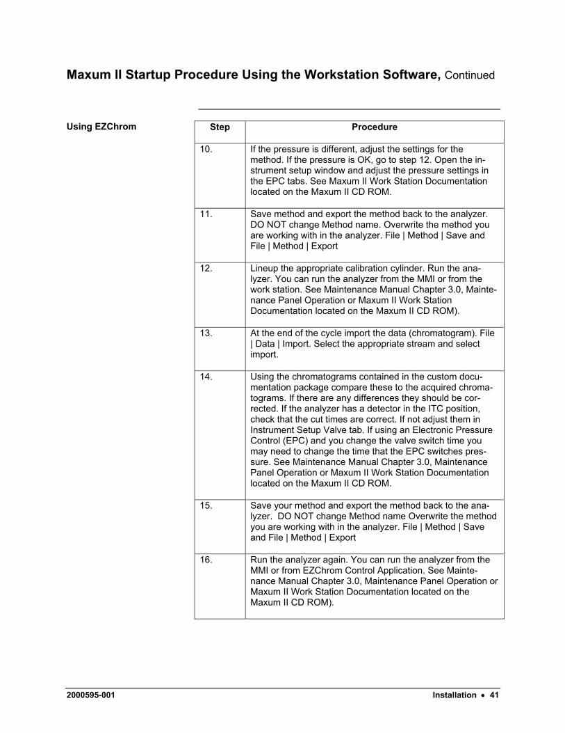
10. If the pressure is different, adjust the settings for the method. If the pressure is OK, go to step 12. Open the in-strument setup window and adjust the pressure settings in the EPC tabs. See Maxum II Work Station Documentation located on the Maxum II CD ROM.
11. Save method and export the method back to the analyzer. DO NOT change Method name. Overwrite the method you are working with in the analyzer. File | Method | Save and File | Method | Export
12. Lineup the appropriate calibration cylinder. Run the ana-lyzer. You can run the analyzer from the MMI or from the work station. See Maintenance Manual Chapter 3.0, Mainte-nance Panel Operation or Maxum II Work Station Documentation located on the Maxum II CD ROM).
13. At the end of the cycle import the data (chromatogram). File | Data | Import. Select the appropriate stream and select import.
14. Using the chromatograms contained in the custom docu-mentation package compare these to the acquired chroma-tograms. If there are any differences they should be cor-rected. If the analyzer has a detector in the ITC position, check that the cut times are correct. If not adjust them in Instrument Setup Valve tab. If using an Electronic Pressure Control (EPC) and you change the valve switch time you may need to change the time that the EPC switches pres-sure. See Maintenance Manual Chapter 3.0, Maintenance Panel Operation or Maxum II Work Station Documentation located on the Maxum II CD ROM.
15. Save your method and export the method back to the ana-lyzer. DO NOT change Method name Overwrite the method you are working with in the analyzer. File | Method | Save and File | Method | Export
16. Run the analyzer again. You can run the analyzer from the MMI or from EZChrom Control Application. See Mainte-nance Manual Chapter 3.0, Maintenance Panel Operation or Maxum II Work Station Documentation located on the Maxum II CD ROM).
2000595-001 Installation • 41

Maxum II Startup Procedure Using the Workstation Software, Continued
Step Procedure
17. At the end of the cycle import the data (chromatogram). File | Data | Import. Select the appropriate stream and select import.
18. Using the chromatograms contained in the custom docu-mentation compare them to the acquired. If there are any differences they should be corrected. Repeat steps 15 – 18 until the ITC chromatograms look correct.
19. Using the chromatograms contained in the custom docu-mentation compare them to the acquired chromatograms. Check the component peak retention times and gating. If there are any discrepancies they should be corrected. Ad-just the peak retention times as necessary. See Work Sta-tion documentation, EZChrom help on Method Development | Calibration | Peak Table located on the Maxum II CD ROM.
20. Integrate the Chromatogram to verify the changes. Analysis | Analyze. You may want to place annotations on the chro-matograms so you can visually see the changes you make. To add annotations see EZChrom Basic Operations | Chro-matogram Window | Chromatogram Annotations.
21. Save your method and export the method back to the ana-lyzer. DO NOT change Method name. Overwrite the method you are working with in the analyzer. File | Method | Save and File | Method | Export.
22. Run the analyzer again. You can run the analyzer from the MMI or from EZChrom Control Application. See Chapter 3.0, Maintenance Panel Operation or Maxum II Work Station Documentation located on the Maxum II Library CD.
23. At the end of the cycle import the data (chromatogram). File | Data | Import. Select the appropriate stream and select import.
24. Using the chromatograms in the custom documentation compare the acquired chromatograms to the ones in the custom documentation. If there are any differences they should be corrected. Repeat steps 19 – 24 until the Main chromatograms look correct.
42 • Installation 2000595-001

Maxum II Startup Procedure Using the Workstation Software, Continued
Step Procedure
25. The analyzer is ready to be calibrated. Save the last ac-quired chromatogram to be calibrated. Analysis | Single Level Calibration. See EZChrom documentation | Calibration Using a Stored Data File located on the Maxum II CD ROM.
26. You may want to verify calibration. See EZChrom documen-tation | Reviewing Calibration Curves.
27. Save your method and export the method back to the ana-lyzer. DO NOT change Method name. Overwrite the method you are working with in the analyzer. File | Method | Save and File | Method | Export
28. Run the analyzer again. You can run the analyzer from the MMI or from EZChrom Control Application. See Mainte-nance Manual Chapter 3.0, Maintenance Panel Operation or Maxum II Work Station Documentation located on the Maxum II CD ROM.
29. At the end of the cycle import the data (chromatogram). File | Data | Import. Select the appropriate stream and select import and verify that the analyzer is reading correctly.
Using the System Manager
30. Backup the analyzer database. You may have to wait until the icon appears in the system view window or you can add it manually if you know the analyzers IP address. (see Work Station, Advance System Manager Help File located on the Maxum II CD ROM for Add Unit and Backup/Restore. Rec-ommended file name format is AX###.amd.
31. Put the analyzer in RUN.
2000595-001 Installation • 43

Assigning IP & Sub Network Mask Addresses
All Maxum II units connected to a network must have a unique 32-bit IP and sub network mask (subnetmask) address. The subnetmask together with the IP address is used to define the logical network number of the device. The user must assign the addresses before the unit is network operational.
Overview
Definitions IP Address. The IP address is a 32-bit address that defines each Maxum II’s network ID and host ID. Typically the customer’s network administrator assigns the address. The address IP is entered in a dotted decimal notation format; example: xxx.xxx.xxx.xxx.
Subnetmask. The subnetmask defines which portion of the IP address is the network address and which portion is the host or device address. The subnetmask is a 32-bit value containing one bits for the network and subnet ID and zero bits for the host ID. The subnetmask is ANDed with the IP address to determine which portion of the IP address is the net-work address. For example, with the IP address 192.165.0.1 and a sub-netmask of 255.255.0.0 the network address is 192.165.X.X and the host or device address is X.X.0.1 (network.network.device.device). This par-ticular subnetmask is a Class B address and provides 16 bits for the lo-cal address. This means that with a Class B address mask there is room for 2^16 or 65535 unique host addresses. There are four standard sub-net classes: Class A, B, C, D.
If the unit will be in a closed plant area and not connected to the Internet you can use the factory set addresses or you can select an address:
How to Assign an IP & Sub Net Address
For an IP Address you can select an address within-the entire range of 192.165.0.xxx (xxx equals 000 to 255). For a sub net mask address you can select an address within-the entire range of 255.255.0.xxx (xxx equals 000 to 255). Typically the same subnet mask is used on all Maxum II’s on a given network. Ex: 255.255.000.000.
Ask your network administrator to assign the addresses within the speci-fied range.
The MMI can be used to view or modify the factory set addresses. From the main menu use the following menu path:
Setting Maxum II IP Address
MENU → Setup → System
Access to main menu is obtained by pressing the Menu softkey on the Measurement screen.
Go to line 11 and 12 and change IP and IP mask addresses in accor-dance with the input form your network administrator.
44 • Installation 2000595-001

Requesting Start-Up Assistance
When the analyzer is mounted and all of the connections are made, no-tify your Siemens Applied Automation representative or authorized agent. A specialist can be sent to assist you in starting up the equipment and preparing it for use.
Instructions
Siemens Applied Automation Customer Service Department 500 Highway 60 West Bartlesville, Oklahoma 74003
Inside Oklahoma: (918) 662-7430 Outside Oklahoma: (800) 448-8224 Internationally: 001-918-662-7430
2000595-001 Installation • 45

Siemens Applied Automation A business of Siemens Energy Automation, Inc.
500 Highway 60 West, Bartlesville, OK 74003 Phone 918-662-7000, Fax 918-662-7052