maxtune canopen for can and ethercat drives … canopen for can and ethercat drives reference manual...
TRANSCRIPT
SYSTEMS
www.pbasystems.com.sg
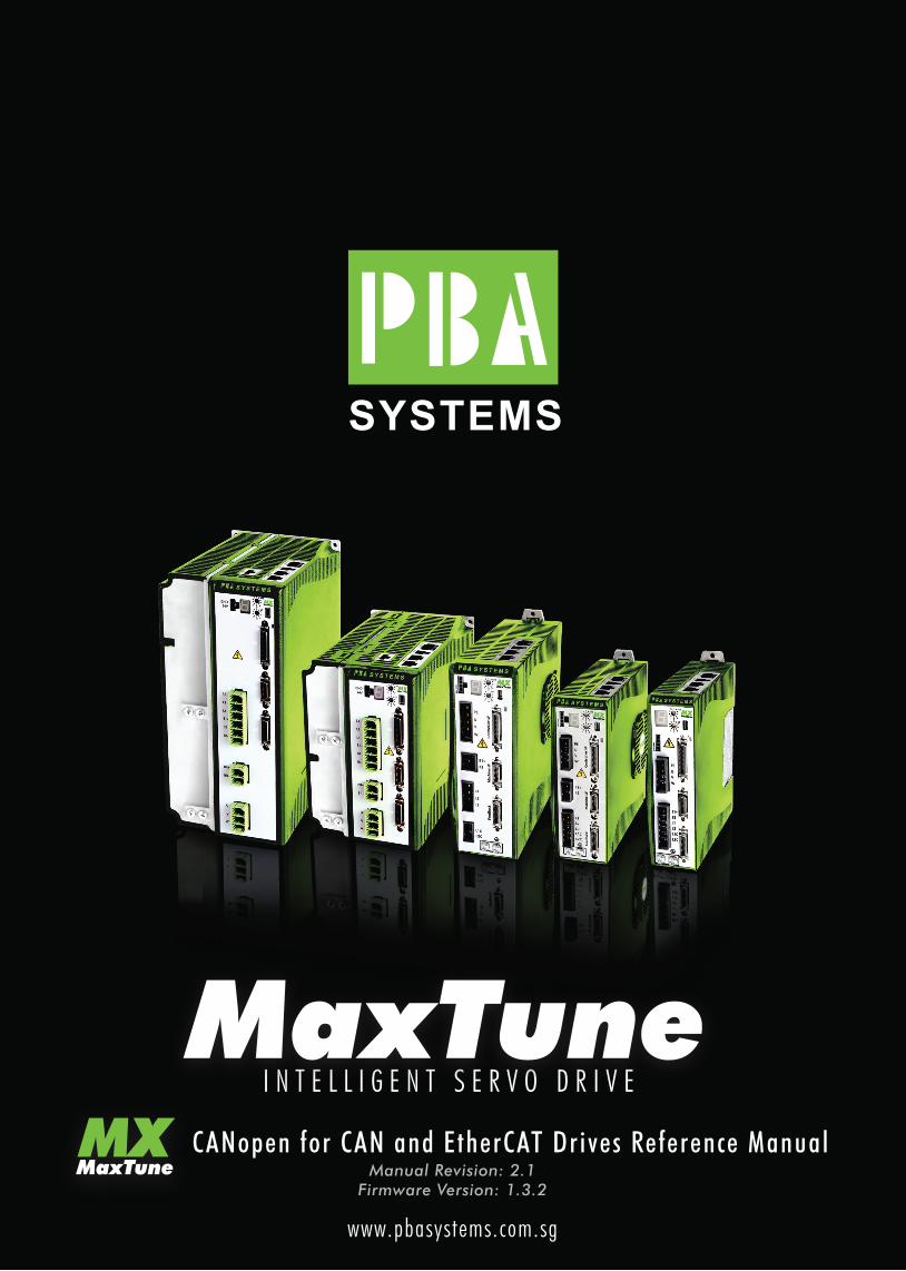
I N T E L L I G E N T S E R V O D R I V E
CANopen for CAN and EtherCAT Drives Reference ManualManual Revision: 2.1
Firmware Version: 1.3.2

MaxTune
CANopen for CAN and EtherCAT Drives Reference Manual 3
Revision History
Document
Revision
Date Remarks
2.1 Jan. 2013 General Release
2.0 Jan. 2013 Preliminary Release
1.0 Aug. 2012 Internal release
Firmware
Revision
1.3.2
Important Notice
© 2013 PBA Systems Pte. Ltd.
All rights reserved. No part of this work may be reproduced or transmitted in any
form or by any means without prior written permission of PBA Systems .
Disclaimer
The information in this manual was accurate and reliable at the time of its
release. PBA Systems Pte. Ltd. reserves the right to change the specifications of
the product described in this manual without notice at any time.
Trademarks
CANopen and CiA are registered trademarks of the CAN in Automation User's
Group
PROFINET is a trademark of PROFIBUS International
EtherCAT is a registered trademark and patented technology, licensed by
Beckhoff Automation GmbH
EnDat is a registered trademark of Dr. Johannes Heidenhain GmbH
HIPERFACE is a registered trademark of Sick Stegmann Gmbh
Windows is a registered trademark of Microsoft Corporation
Contact Information
PBA Systems Pte. Ltd
PBA Building, 505 Yishun,
Industrial Park A, Singapore 7687332
Tel: (+65) 6576 6767
Fax: (+65) 6576 6768
Website: http://www.pbasystems.com.sg/
Email: [email protected]
Technical Support
If you need assistance with the installation and configuration of the MaxTune
drive, contact technical support: [email protected]
MaxTune
4 CANopen for CAN and EtherCAT Drives Reference Manual
MaxTune
CANopen for CAN and EtherCAT Drives Reference Manual 5
MaxTune
6 CANopen for CAN and EtherCAT Drives Reference Manual
Contents
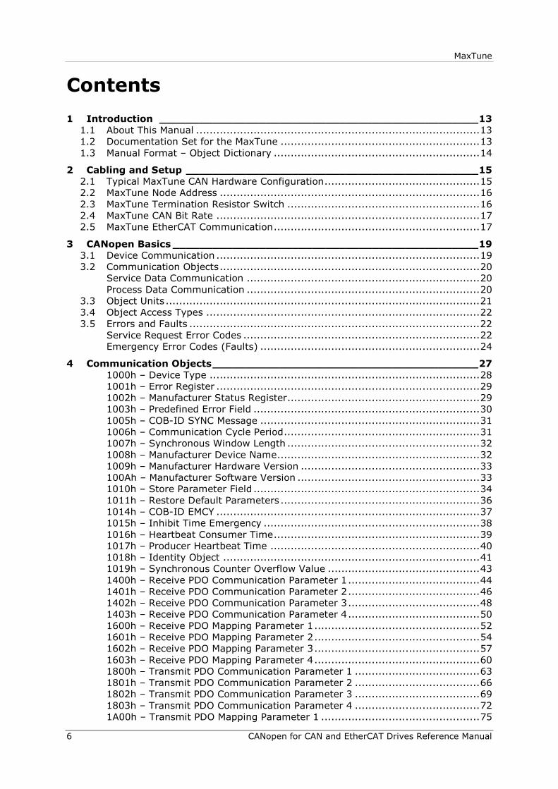
1 Introduction ________________________________________________ 13
1.1 About This Manual .................................................................................... 13
1.2 Documentation Set for the MaxTune ........................................................... 13
1.3 Manual Format – Object Dictionary ............................................................. 14
2 Cabling and Setup ____________________________________________ 15
2.1 Typical MaxTune CAN Hardware Configuration .............................................. 15
2.2 MaxTune Node Address ............................................................................. 16
2.3 MaxTune Termination Resistor Switch ......................................................... 16
2.4 MaxTune CAN Bit Rate .............................................................................. 17
2.5 MaxTune EtherCAT Communication ............................................................. 17
3 CANopen Basics ______________________________________________ 19
3.1 Device Communication .............................................................................. 19
3.2 Communication Objects ............................................................................. 20
Service Data Communication ..................................................................... 20
Process Data Communication ..................................................................... 20
3.3 Object Units ............................................................................................. 21
3.4 Object Access Types ................................................................................. 22
3.5 Errors and Faults ...................................................................................... 22
Service Request Error Codes ...................................................................... 22
Emergency Error Codes (Faults) ................................................................. 24
4 Communication Objects ________________________________________ 27
1000h – Device Type ................................................................................ 28
1001h – Error Register .............................................................................. 29
1002h – Manufacturer Status Register ......................................................... 29
1003h – Predefined Error Field ................................................................... 30
1005h – COB-ID SYNC Message ................................................................. 31
1006h – Communication Cycle Period .......................................................... 31
1007h – Synchronous Window Length ......................................................... 32
1008h – Manufacturer Device Name ............................................................ 32
1009h – Manufacturer Hardware Version ..................................................... 33
100Ah – Manufacturer Software Version ...................................................... 33
1010h – Store Parameter Field ................................................................... 34
1011h – Restore Default Parameters ........................................................... 36
1014h – COB-ID EMCY .............................................................................. 37
1015h – Inhibit Time Emergency ................................................................ 38
1016h – Heartbeat Consumer Time ............................................................. 39
1017h – Producer Heartbeat Time .............................................................. 40
1018h – Identity Object ............................................................................ 41
1019h – Synchronous Counter Overflow Value ............................................. 43
1400h – Receive PDO Communication Parameter 1 ....................................... 44
1401h – Receive PDO Communication Parameter 2 ....................................... 46
1402h – Receive PDO Communication Parameter 3 ....................................... 48
1403h – Receive PDO Communication Parameter 4 ....................................... 50
1600h – Receive PDO Mapping Parameter 1 ................................................. 52
1601h – Receive PDO Mapping Parameter 2 ................................................. 54
1602h – Receive PDO Mapping Parameter 3 ................................................. 57
1603h – Receive PDO Mapping Parameter 4 ................................................. 60
1800h – Transmit PDO Communication Parameter 1 ..................................... 63
1801h – Transmit PDO Communication Parameter 2 ..................................... 66
1802h – Transmit PDO Communication Parameter 3 ..................................... 69
1803h – Transmit PDO Communication Parameter 4 ..................................... 72
1A00h – Transmit PDO Mapping Parameter 1 ............................................... 75

MaxTune
CANopen for CAN and EtherCAT Drives Reference Manual 7
1A01h – Transmit PDO Mapping Parameter 2 ............................................... 78
1A02h – Transmit PDO Mapping Parameter 3 ............................................... 81
1A03h – Transmit PDO Mapping Parameter 4 ............................................... 84
5 Manufacturer-Specific Objects___________________________________ 87
2001h – Go to Resident ............................................................................. 87
2002h – Configuration Command ............................................................... 88
2003h – CL BEMF Gain .............................................................................. 88
2004h – Current DQ Axis Compensation ...................................................... 89
2005h – Current KFF Gain ......................................................................... 89
2006h – Current KI Gain ........................................................................... 90
2007h – Current KP Gain ........................................................................... 90
2008h – Current Controller D Integrator ...................................................... 91
2009h – Current Controller Q Integrator ...................................................... 91
200Ah – HD Anti-Vibration Filter ................................................................. 92
200Bh – HD Anti-Resonance Sharpness ....................................................... 92
200Ch – HD Anti-Vibration Gain ................................................................. 93
200Dh – Absolute Feedback Offset .............................................................. 93
200Eh – Auto Home Mode.......................................................................... 94
200Fh – Field Bus Unit Scaling ................................................................... 94
2010h – Velocity Loop Bandwidth ............................................................... 95
2013h – Current CL VD ............................................................................. 95
2014h – Current CL VQ ............................................................................. 96
2015h – Drive Name ................................................................................. 96
2016h – Electrical Position ......................................................................... 97
2017h – HD Derivative Gain ....................................................................... 97
2018h – HD Integral Gain .......................................................................... 98
2019h – HD Derivative-Integral Gain .......................................................... 98
201Ah – HD Proportional Gain .................................................................... 99
201Bh – HD Adaptive Gain Scale Factor....................................................... 99
201Ch – Position Acceleration Feedforward to Current ................................. 100
201Dh – Position Acceleration Feedforward ................................................ 100
201Eh – Position Derivative Gain .............................................................. 101
201Fh – Position Proportional Adaptive Gain .............................................. 101
2020h – Position Integral Gain ................................................................. 102
2021h – Position Integral Saturation Output .............................................. 102
2022h – Position Proportional Gain ........................................................... 103
2023h – Position Velocity Feedforward ...................................................... 103
2025h – Velocity Feedforward Ratio .......................................................... 104
2026h – Velocity Integrator ..................................................................... 104
2027h – Velocity Gain ............................................................................. 105
2028h – Mechanical Angle ....................................................................... 105
2029h – Encoder Type............................................................................. 106
202Ah – Motor Encoder Index Position ...................................................... 106
202Bh – Motor and Feedback Direction ...................................................... 107
202Dh – Motor Feedback Mode ................................................................. 107
202Eh – Motor Foldback Status ................................................................ 108
202Fh – Motor Foldback Delay Time .......................................................... 108
2030h – Motor Foldback Disable ............................................................... 109
2031h – Motor Foldback Recovery Time ..................................................... 109
2032h – Motor Foldback Time Constant ..................................................... 110
2033h – Motor Foldback Current ............................................................... 110
2034h – Motor Foldback Fault Threshold .................................................... 111
2035h – Motor Foldback Warning Threshold ............................................... 111
2036h – Motor Peak Current .................................................................... 112
2037h – Rotor Inertia .............................................................................. 112
2038h – Torque Constant for Linear Motors................................................ 113

MaxTune
8 CANopen for CAN and EtherCAT Drives Reference Manual
2039h – Torque Constant ........................................................................ 113
203Ah – Motor Inductance ....................................................................... 114
203Bh – Adaptive Gain Value at Continuous Motor Current .......................... 114
203Ch – Adaptive Gain Value at Peak Motor Current ................................... 115
203Dh – Rotor Coil Mass (Linear Motor) .................................................... 115
203Eh – Motor Commutation Type ............................................................ 116
203Fh – Motor Name ............................................................................... 116
2040h – Phase Disconnect Scan ............................................................... 117
2043h – Commutation Offset ................................................................... 117
2044h – Drive Temperature ..................................................................... 118
2045h – Feedback Direction ..................................................................... 119
2046h – Disabling Mode .......................................................................... 120
2047h – Capture Input Position Offset ....................................................... 120
2048h – Capture Input Position Offset 2 .................................................... 121
2049h – Quick Stop Deceleration Time ...................................................... 121
204Ah – Active Disable Speed Threshold ................................................... 122
204Bh – Active Disable Time .................................................................... 122
204Ch – Factory Restore ......................................................................... 123
204Dh – Feedback Type .......................................................................... 123
204Eh – Velocity Loop Output Filter Parameter 1 ........................................ 124
204Fh – Velocity Loop Output Filter Parameter 2 ........................................ 124
2050h – Velocity Loop Output Filter .......................................................... 125
2051h – Foldback Status ......................................................................... 125
2052h – Friction Compensation Negative Current ....................................... 126
2053h – Friction Compensation Positive Current ......................................... 126
2054h – Friction Compensation Negative Velocity Hysteresis ........................ 127
2055h – Friction Compensation Positive Velocity Hysteresis ......................... 127
2056h – Halls State ................................................................................ 128
2057h – Invert Hall Signals ...................................................................... 130
2058h – Hall Signals Type ....................................................................... 131
2059h – Harmonic Correction Feedback ..................................................... 132
205Ah – Harmonic Correction Feedback Parameter1 ................................... 132
205Bh – Harmonic Correction Feedback Parameter 2 .................................. 134
205Ch – Harmonic Correction Current ....................................................... 137
205Dh – Harmonic Current ICMD Parameter 1 ........................................... 138
205Eh – Harmonic Current ICMD Parameter 2 ............................................ 140
205Fh – HD Current LPF Rise Time ........................................................... 142
2060h – HD Current Filter Damping .......................................................... 142
2061h – Current Notch Filter Center.......................................................... 143
2062h – HD Current Notch Filter Bandwidth ............................................... 143
2063h – Hold Position Command .............................................................. 144
2064h – Hardware Position External .......................................................... 144
2065h – Hardware Position ...................................................................... 145
2066h – Current D Axis ........................................................................... 145
2067h – Current Q Axis ........................................................................... 146
2068h – Current Feedforward LPF ............................................................. 146
2069h – Drive Foldback Current Limit ....................................................... 147
206Ah – Drive Foldback Fault Threshold .................................................... 147
206Bh – Drive Foldback Warning Threshold ............................................... 148
206Ch – Gravity Compensation ................................................................ 148
206Dh – Encoder Index Initialization ......................................................... 149
206Eh – Encoder Initialization Status ........................................................ 149
206Fh – Encoder Index Position Feedback.................................................. 150
2070h – Input Inversion .......................................................................... 150
2071h – Dynamic Brake Current ............................................................... 152
2072h – Phase U Actual Current ............................................................... 152
2073h – Phase U Current Offset ............................................................... 153

MaxTune
CANopen for CAN and EtherCAT Drives Reference Manual 9
2074h – Phase V Actual Current ............................................................... 153
2075h – Phase V Current Offset................................................................ 154
2076h – Zero Procedure Current .............................................................. 154
2077h – Position Integral Saturation Input ................................................. 155
2078h – Negative Limit Switch Status ....................................................... 155
2079h – Positive Limit Switch Status ......................................................... 156
207Ah – Load to Motor Inertia Ratio .......................................................... 156
207Bh – Drive Peak Current ..................................................................... 157
207Ch – Drive Continuous Current ............................................................ 157
207Dh – Motor Pitch ............................................................................... 158
207Eh – Motor Poles ............................................................................... 158
207Fh – Motor Resistance ........................................................................ 159
2080h – Motor Resolver Poles .................................................................. 159
2081h – Motor Rated Torque .................................................................... 160
2083h – Torque Commutation Angle Advance at Motor Continuous Current ... 160
2084h – Torque Commutation Angle Advance at Motor Peak Current ............ 161
2085h – Velocity Commutation Angle Advance at Motor Maximum Speed ...... 161
2086h – Velocity Commutation Angle Advance at Motor Maximum Speed/2 ... 162
2087h – HD Spring Filter ......................................................................... 162
2088h – PFB Backup ............................................................................... 163
2089h – PFB Backup Mode ....................................................................... 163
208Ah – HD Maximum Adaptive Gain ........................................................ 164
208Bh – HD Current Filter – Second Notch Filter Bandwidth ......................... 164
208Ch – HD Current Filter – Second Notch Filter Center .............................. 165
208Fh – HD Flexibility Compensation ........................................................ 165
2091h – HD Spring Deceleration Ratio ....................................................... 166
2092h – HD Settling Mode ....................................................................... 166
2093h – HD Autotune Command .............................................................. 167
2094h – HD Autotune Procedure Parameter ............................................... 167
2097h – HD Autotune Status .................................................................... 168
2098h – HD Autotune Timeout ................................................................. 168
2099h – Current Level 1 for Digital Output Definition .................................. 169
209Ah – Current Level 2 for Digital Output Definition .................................. 169
209Bh – Output Inversion ........................................................................ 170
209Ch – Output Mode ............................................................................. 172
209Dh – Position Level 1 for Digital Output Definition .................................. 174
209Eh – Position Level 2 for Digital Output Definition .................................. 174
209Fh – Velocity Level 1 for Digital Output Definition .................................. 175
20A0h – Velocity Level 2 for Digital Output Definition .................................. 175
20A1h – Over-Voltage Threshold .............................................................. 176
20A2h – In Position Time ......................................................................... 176
20A3h – Position Loop Position Error ......................................................... 177
20A4h – Phase Find Command ................................................................. 177
20A5h – Forced Electrical Position ............................................................. 178
20A6h – Phase Find Gain ......................................................................... 178
20A7h – Phase Find Current ..................................................................... 179
20A8h – Phase Find Mode ........................................................................ 179
20A9h – Phase Find Status ...................................................................... 180
20AAh – Phase Find Duration ................................................................... 180
20ABh – Position Loop Controller Mode ...................................................... 181
20ACh – Software Position Limit Mode ....................................................... 181
20ADh – PRB Generator Frequency ........................................................... 182
20AEh – PRB Generator Mode .................................................................. 182
20AFh – PRB Generator Configuration ....................................................... 183
20B0h – PTP Generator Target Error ......................................................... 186
20B1h – PTP Generator Velocity Command ................................................ 186
20B2h – PWM Frequency ......................................................................... 187

MaxTune
10 CANopen for CAN and EtherCAT Drives Reference Manual
20B4h – PWM Saturation Ratio ................................................................. 187
20B8h – Fault Relay Status ...................................................................... 188
20B9h – Fault Relay Mode ....................................................................... 188
20BAh – Remote Hardware Enable Status .................................................. 189
20BBh – Resolver Amplitude Range .......................................................... 189
20BCh – Resolver Conversion Bandwidth ................................................... 190
20BDh – Save Parameters ....................................................................... 190
20BEh – Sine/Cosine Calibration Command ................................................ 191
20BFh – Sine/Cosine Calibration Mode....................................................... 192
20C0h – Sine/Cosine Calibration Status ..................................................... 192
20C1h – Sine/Cosine Calibration Parameters .............................................. 193
20C2h – Synchronization Mode ................................................................. 193
20C3h – Tracking Factor .......................................................................... 194
20C4h – Motor Over-Temperature ............................................................ 194
20C5h – Motor Over-Temperature Clear Fault Level .................................... 195
20C6h – Motor Over-Temperature Mode .................................................... 195
20C7h – Motor Temperature .................................................................... 196
20C8h – Motor Over-Temperature Time ..................................................... 196
20C9h – Motor Over-Temperature Fault Level ............................................ 197
20CAh – Motor Over-Temperature Type .................................................... 197
20CBh – Tamagawa Multi-Turn Reset ........................................................ 198
20CCh – Run Time .................................................................................. 198
20CDh – Under-Voltage Mode .................................................................. 199
20CEh – Under-Voltage Recovery Mode ..................................................... 200
20CFh – Under-Voltage Threshold ............................................................. 200
20D0h – Under-Voltage Time ................................................................... 201
20D1h – Bus Voltage (DC) ....................................................................... 201
20D3h – Velocity Error ............................................................................ 202
20D4h – Velocity Loop Controller .............................................................. 203
20D5h – Velocity Design Structure ............................................................ 204
20D6h – Velocity Filter Mode .................................................................... 204
20D7h – Drive Version ............................................................................ 205
20D8h – Velocity Loop Output Filter .......................................................... 205
20D9h – Velocity Loop Input Filter ............................................................ 209
20DAh – Advanced Pole Placement H Polynomial ........................................ 212
20DBh – Advanced Pole Placement R Polynomial ........................................ 217
20DCh – Wake No Shake Status ............................................................... 222
20DDh – Display Warnings....................................................................... 222
20DEh – External Encoder Resolution ........................................................ 223
20DFh – Zeroing Command ..................................................................... 223
20E0h – Input Mode ................................................................................ 224
20E1h – Rotary Address Switch ................................................................ 226
20E2h – Test 7-Segment Display .............................................................. 226
20E3h – Encoder Simulation Mode ............................................................ 227
20E4h – Encoder Simulation Resolution ..................................................... 227
20E5h – Encoder Simulation Index Position ................................................ 228
20E6h – Record Done Indicator ................................................................ 228
6 Standard Servo Drive Objects __________________________________ 229
603Fh – Error Code ................................................................................. 230
6040h – Controlword .............................................................................. 230
6041h – Statusword ................................................................................ 231
6060h – Modes of Operation .................................................................... 232
6061h – Modes of Operation Display ......................................................... 233
6064h – Position Actual Value .................................................................. 234
6065h – Following Error Window............................................................... 234
606Ch – Velocity Actual Value .................................................................. 235
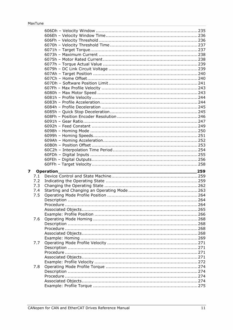
MaxTune
CANopen for CAN and EtherCAT Drives Reference Manual 11
606Dh – Velocity Window ........................................................................ 235
606Eh – Velocity Window Time ................................................................. 236
606Fh – Velocity Threshold ...................................................................... 236
6070h – Velocity Threshold Time .............................................................. 237
6071h – Target Torque ............................................................................ 237
6073h – Maximum Current ...................................................................... 238
6075h – Motor Rated Current ................................................................... 238
6077h – Torque Actual Value ................................................................... 239
6079h – DC Link Circuit Voltage ............................................................... 239
607Ah – Target Position .......................................................................... 240
607Ch – Home Offset .............................................................................. 240
607Dh – Software Position Limit ............................................................... 241
607Fh – Max Profile Velocity .................................................................... 243
6080h – Max Motor Speed ....................................................................... 243
6081h – Profile Velocity ........................................................................... 244
6083h – Profile Acceleration ..................................................................... 244
6084h – Profile Deceleration .................................................................... 245
6085h – Quick Stop Deceleration .............................................................. 245
608Fh – Position Encoder Resolution ......................................................... 246
6091h – Gear Ratio ................................................................................. 247
6092h – Feed Constant ........................................................................... 249
6098h – Homing Mode ............................................................................ 250
6099h – Homing Speeds .......................................................................... 251
609Ah – Homing Acceleration ................................................................... 252
60B0h – Position Offset ........................................................................... 253
60C2h – Interpolation Time Period ............................................................ 254
60FDh – Digital Inputs ............................................................................ 255
60FEh – Digital Outputs ........................................................................... 256
60FFh – Target Velocity ........................................................................... 258
7 Operation __________________________________________________ 259
7.1 Device Control and State Machine ............................................................. 259
7.2 Indicating the Operating State ................................................................. 259
7.3 Changing the Operating State .................................................................. 262
7.4 Starting and Changing an Operating Mode ................................................. 263
7.5 Operating Mode Profile Position ................................................................ 264
Description ............................................................................................ 264
Procedure .............................................................................................. 264
Associated Objects .................................................................................. 265
Example: Profile Position ......................................................................... 266
7.6 Operating Mode Homing .......................................................................... 268
Description ............................................................................................ 268
Procedure .............................................................................................. 268
Associated Objects .................................................................................. 268
Example: Homing ................................................................................... 269
7.7 Operating Mode Profile Velocity ................................................................ 271
Description ............................................................................................ 271
Procedure .............................................................................................. 271
Associated Objects .................................................................................. 271
Example: Profile Velocity ......................................................................... 272
7.8 Operating Mode Profile Torque ................................................................. 274
Description ............................................................................................ 274
Procedure .............................................................................................. 274
Associated Objects .................................................................................. 274
Example: Profile Torque .......................................................................... 275


MaxTune Introduction
Reference Manual 13
1 Introduction
1.1 About This Manual
MaxTune drive functionality is configured using various commands and variables,
which are communicated over the serial port or over CAN bus.
This manual describes the implementation of CiA 402 and 301 CANopen
protocols in the MaxTune digital servo drive. This manual is not meant to replace
the CANopen specifications, or to reproduce them.
This manual is intended for skilled personnel who have been trained to work with
the equipment described.
1.2 Documentation Set for the MaxTune
This manual is part of a documentation set. The entire set consists of the
following:
MaxTune Quick Start Guide. Basic setup and operation of the drive.
MaxTune User Manual. Hardware installation, configuration and operation.
MaxTune VarCom Reference Manual. Parameters and commands used to
program the MaxTune.
MaxTune CANopen for CAN and EtherCAT Drives Reference Manual.
MaxTune implementation of CANopen protocol for CAN and EtherCAT.
Introduction MaxTune
14 Reference Manual
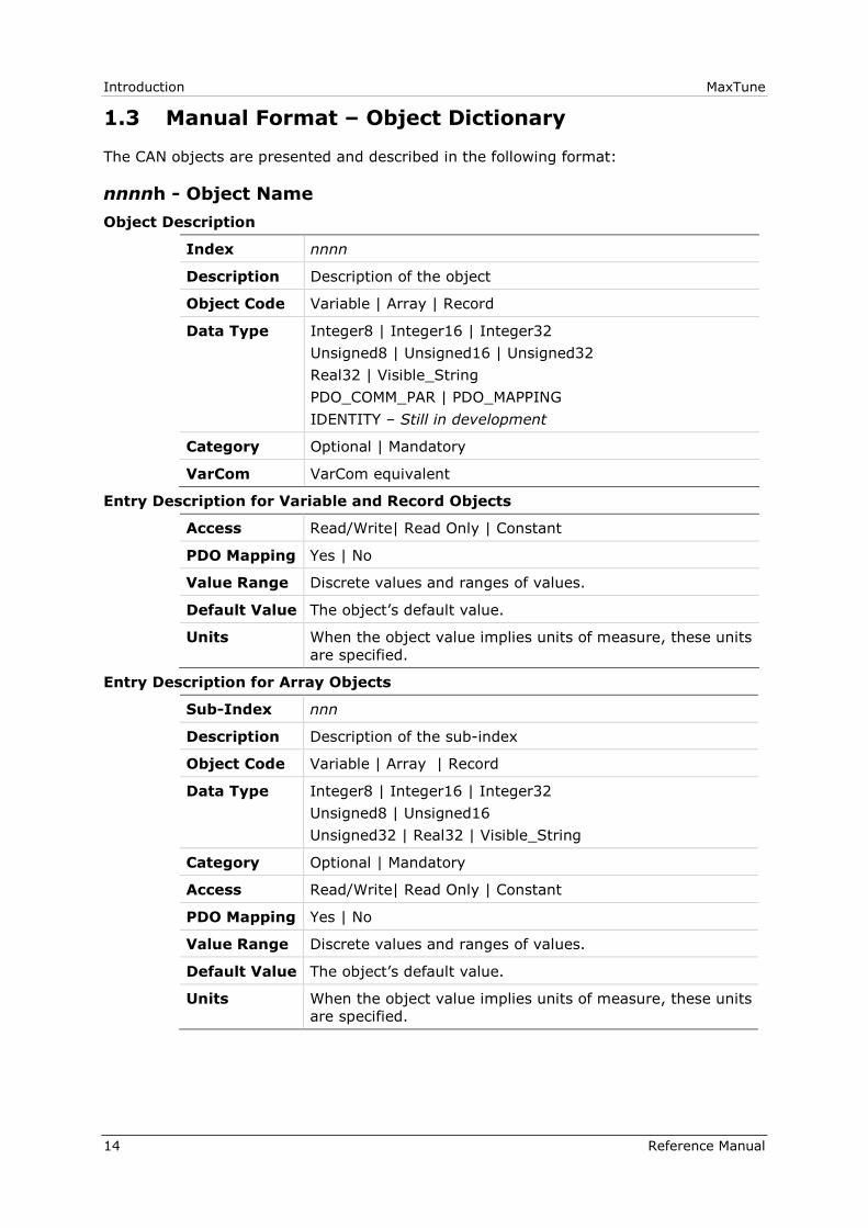
1.3 Manual Format – Object Dictionary
The CAN objects are presented and described in the following format:
nnnnh - Object Name
Object Description
Index nnnn
Description Description of the object
Object Code Variable | Array | Record
Data Type Integer8 | Integer16 | Integer32
Unsigned8 | Unsigned16 | Unsigned32
Real32 | Visible_String
PDO_COMM_PAR | PDO_MAPPING
IDENTITY – Still in development
Category Optional | Mandatory
VarCom VarCom equivalent
Entry Description for Variable and Record Objects
Access Read/Write| Read Only | Constant
PDO Mapping Yes | No
Value Range Discrete values and ranges of values.
Default Value The object’s default value.
Units When the object value implies units of measure, these units
are specified.
Entry Description for Array Objects
Sub-Index nnn
Description Description of the sub-index
Object Code Variable | Array | Record
Data Type Integer8 | Integer16 | Integer32
Unsigned8 | Unsigned16
Unsigned32 | Real32 | Visible_String
Category Optional | Mandatory
Access Read/Write| Read Only | Constant
PDO Mapping Yes | No
Value Range Discrete values and ranges of values.
Default Value The object’s default value.
Units When the object value implies units of measure, these units
are specified.

MaxTune Cabling and Setup
Reference Manual 15
2 Cabling and Setup
2.1 Typical MaxTune CAN Hardware Configuration
Figure 2-1. Typical MaxTune CAN Configuration
1 PLC or embedded PC
2 CAN bus module*
3
D9 to RJ45 adapter*, with following pin assignments
Function MaxTune RJ45 Pin D9 Connector Pin
CAN High 1 7
CAN Low 2 2
Functional Ground 3 3
CAN Shield 4 5
Functional Ground 5 6
4 RJ45 cables
5 MaxTune with internal termination set to 0Ω (towards T)
6 Last MaxTune, with internal terminator set to 120Ω (away from T)

Cabling and Setup MaxTune
16 Reference Manual
* A 120Ω termination resistor is required at the beginning of the chain.
Be sure the required EDS file is installed in the controller. You can download the
file from the MaxTune product page on the website.
For additional information, refer to the MaxTune User Manual.
2.2 MaxTune Node Address
Within the CANopen network, a unique node address (identification number)
must be allocated to each individual CANopen device. The MaxTune node
address is set using two 10-position rotary switches, accessible from the front of
the unit.
Each switch has 10 positions:
The upper switch positions are set as tens: 10, 20, 30 … 90
The lower switch positions are set as ones: 0, 1, 2 … 9
Notes: If two or more drives are connected to the network, address 0 cannot
be used. Only a singular drive may have the address 0.
Two drives in the same network cannot have the same address.
2.3 MaxTune Termination Resistor Switch
Note the Termination Resistor switch located on the top of the drive next to the
daisy chain connector (C8). Using a small screwdriver or similar tool, set the
switch to the correct position:
Towards T (default): 120Ω termination resistor not in use.
Away from T: Used when the drive is the last drive in a chain. The drive
provides the 120Ω termination resistor between CAN high and CAN low.
Using any RJ45 cables:
Connect the host to the drive on interface C5.
Connect the next node to interface C6.
Note: A 120Ω termination resistor is also required at the beginning of the
chain, on either the CAN bus module, or the D9 to RJ45 adapter.

MaxTune Cabling and Setup
Reference Manual 17
For additional wiring information, refer to the MaxTune User Manual.
In addition, to enable CAN communication, the RS-232 (VarCom) command
COMMODE must be set to 1.
2.4 MaxTune CAN Bit Rate
MaxTune has an automatic bit rate detection mechanism that is executed on
power up. During the initialization phase the drive listens to messages on the
bus and automatically adjusts its bit rate setting.
Once the bit rate is determined, the drive’s status becomes pre-operational, and
the drive transmits a boot up message containing the drive's node ID.
For the automatic bit rate detection mechanism to work, there must be bus
traffic. This means that a master and at least one slave must be present on the
bus and communicating at the same bit rate.
It is also possible to set the manual bit rate using the RS-232 (VarCom)
command CANBITRATE. This command takes one of the following values:
1 for 125 kilobit per second
2 for 250 kilobit per second
3 for 500 kilobit per second
4 for 1000 kilobit per second (1 megabit)
After setting the CANBITRATE value, you must issue a RS-232 (VarCom)
command SAVE, and then power cycle the drive. The bit rate will then be set.
2.5 MaxTune EtherCAT Communication
Using any RJ45 cables:
Connect the host to the drive on interface C5.
Connect the next node to interface C6.
Be sure the required XML file is installed in the controller. You can download the
file from the MaxTune product page on the website.
For additional information, refer to the MaxTune User Manual.

Cabling and Setup MaxTune
18 Reference Manual
MaxTune CANopen Basics
Reference Manual 19
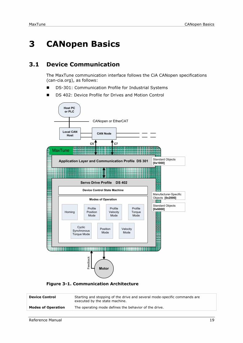
3 CANopen Basics
3.1 Device Communication
The MaxTune communication interface follows the CiA CANopen specifications
(can-cia.org), as follows:
DS-301: Communication Profile for Industrial Systems
DS 402: Device Profile for Drives and Motion Control
CDHD
Servo Drive Profile DS 402
CAN NodeLocal CAN
Host
Host PC
or PLC
Application Layer and Communication Profile DS 301
CANopen or EtherCAT
Feedback
Device Control State Machine
Modes of Operation
Profile
Position
Mode
Homing
Profile
Torque
Mode
Profile
Velocity
Mode
Manufacturer-Specific
Objects [0x2000]
Standard Objects
[0x6000]
Standard Objects
[0x1000]
Motor
C5 C7
Cyclic
Synchronous
Torque Mode
Position
Mode
Velocity
Mode
Figure 3-1. Communication Architecture
Device Control Starting and stopping of the drive and several mode-specific commands are executed by the state machine.
Modes of Operation The operating mode defines the behavior of the drive.
MaxTune
CANopen Basics MaxTune
20 Reference Manual
3.2 Communication Objects
Communication objects are used for exchanging process and service data, for
process or system time synchronization, for error state supervision, and for
control and monitoring of node states. These objects are defined by their
structure, transmission types and their CAN identifier.
Service Data Communication
Service data objects (SDOs) provides direct access to object entries in the
CANopen device object dictionary. As these object entries contain data of
arbitrary size and data type, the SDOs are used to transfer multiple data sets
(each containing an arbitrary large block of data) from a client to a server and
vice versa. The client controls, via a multiplexer (index and sub-index of the
object dictionary), which data set is transferred. The content of the data set is
defined within the object dictionary.
In general, an SDO is transferred as a sequence of segments. Prior to
transferring the segments there is an initialization phase in which client and
server prepare for transferring the segments. For SDOs, it is also possible to
transfer a data set of up to four bytes during the initialization phase. This
mechanism is called SDO expedited transfer.
The client always initiates an SDO transfer for any type of transfer. The owner of
the accessed object dictionary is the server of the SDO. Either the client or the
server can take the initiative to abort the transfer of an SDO.
By means of an SDO, a peer-to-peer communication channel between two
CANopen devices is established. A CANopen device supports more than one SDO.
One supported Server-SDO is the default case (Default SDO).
Process Data Communication
Process data objects (PDOs) perform real-time data transfer. The transfer of
PDOs is performed without any protocol overhead.
The PDOs correspond to objects in the object dictionary and provide the
interface to the application objects. Data type and mapping of application objects
into a PDO is determined by a corresponding default PDO mapping structure
within the object dictionary. MaxTune supports variable PDO mapping; therefore,
the number of PDOs and the mapping of application objects into a PDO may be
transmitted to a CANopen device during the configuration process, by applying
the SDO services to the corresponding objects of the object dictionary.
PDOs are used for both data transmission and data reception – termed
Transmit-PDO (TPDO) and Receive-PDO (RPDO), respectively. CANopen devices
supporting TPDO are PDO producers, and CANopen devices supporting RPDO are
called PDO consumers. MaxTune supports both. The PDO communication
parameter describes the communication capabilities of the PDO. The PDO
mapping parameter contains information about the contents of the PDO.
For each PDO, a pair of communication and mapping parameters is mandatory.
By default 4 TPDOs and 4 RPDOs are implemented in the MaxTune:
TPDO 1 – Statusword, 6041h, 16 bits
TPDO 2 – Position actual value, 6064h, 32 bits
and Velocity actual value, 606Ch, 32 bits
TPDO 3 – Torque actual value, 6077h, 16 bits
TPDO 4 – Digital inputs, 60FDh, 32 bits
MaxTune CANopen Basics
Reference Manual 21
RPDO 1 – Controlword, 6040h, 16 bits
RPDO 2 – Target position, 607Ah, 32 bits
and Target velocity, 6081h, 32 bits
RPDO 3 – Target velocity, 60FFh, 32 bits
RPDO 4 – Target torque, 6071h, 16 bits
3.3 Object Units
Table 3-1. Unit Dimensions
Unit Dimension Definition
Position units The units are: (object 6091h sub-index 1 ÷ 6091h
sub-index 2) × (object 6092h sub-index 1 ÷ 6092h
sub-index 2)
For example:
Assuming:
object 6091h sub-index 1 = 360
object 6091h sub-index 2 = 1
object 6092h sub-index 1 = 1
object 6092h sub-index 2 = 1
and the actual position reading = 720
Then:
720 ÷ [(360÷1) × (1÷1)] = 2
(= 2 revolutions)
Velocity units The units are: (object 6091h sub-index 1 ÷ 6091h
sub-index 2) × (object 6092h sub-index 1 ÷ 6092h
sub-index 2)
For example:
Assuming:
object 6091h sub-index 1 = 360
object 6091h sub-index 2 = 1
object 6092h sub-index 1 = 1
object 6092h sub-index 2 = 1
and the actual velocity reading = 720
Then:
720 ÷ [(360÷1) × (1÷1)] = 2
(= 2 revolutions per second)
Acceleration
units
The units are: (object 6091h sub-index 1 ÷ 6091h
sub-index 2) × (object 6092h sub-index 1 ÷ 6092h
sub-index 2)
For example:
Assuming:
object 6091h sub-index 1 = 360
object 6091h sub-index 2 = 1
object 6092h sub-index 1 = 1
object 6092h sub-index 2 = 1
and the actual acceleration reading = 720
Then:
720 ÷ [(360÷1) × (1÷1)] = 2
(= 2 revolutions per second2)
CANopen Basics MaxTune
22 Reference Manual
Unit Dimension Definition
Current units The units are derived from object 6075h (Motor Rated
Current)
The value of this object is user defined, in mA.
After setting a value for 6075h, all other current objects
must receive values defined in 1/1000 (one-thousandth) of
6075h.
For example: Assuming 6075h has a value of 20000 mA,
then to set a value of 20000 mA for 6071h (Target
Torque), write 1000 for 6071h.
The calculation is: (1000÷1000) × 2000 = 2000
3.4 Object Access Types
Table 3-2. Object Access Types
Unit Dimension Definition
Read/Write Read and write access
Read Only Read only
Constant Read only access, value is constant
3.5 Errors and Faults
Service Request Error Codes
Table 3-3 lists the service request error (abort) codes, which the drive sends to
the master device when the master issues an invalid SDO request to the
MaxTune.
For example, if you write a parameter value to the drive, but the value is higher
than allowed, the drive will respond by sending error code: 0604004Dh (value is
out of range).
Table 3-3. Service Request Error Codes
Error Code Description
0500004Ch Waiting for enable; configuration cannot be executed
0500004Eh The EnDat encoder is currently busy
05000053h The drive configuration is invalid
05000064h Failed to configure the velocity loop
05000069h The drive is currently in Hold mode
0500006Ah The value or service is not currently available
0500006Bh No phase found on Tamagawa encoder
0500006Dh The requested functionality is currently in use and not available
0500006Eh The function is not supported on the input/output
0500006Fh The argument must be an even number

MaxTune CANopen Basics
Reference Manual 23
Error Code Description
05030060h The motor peak rated current conflicts with the motor
continuous rated current (MICONT > MIPEAK)
05030061h The drive peak rated current conflicts with the drive continuous
rated current conflict (DICONT > DIPEAK)
0504004Fh Motor and encoder type mismatch
05040050h Linear motor and encoder type mismatch
05040052h The actual Harmonic current correction is out-of-range
05040054h The position encoder resolution value is invalid
05040055h The motor commutation type is invalid
05040056h The velocity limit is invalid
05040057h The drive peak rated current is invalid (sinusoidal peak)
05040058h The motor peak rated current is invalid
05040059h The drive bus voltage is invalid
0504005Ah The motor minimum line-to-line inductance is invalid
0504005Bh The number of motor poles is invalid
0504005Ch The resolution in number of lines of the encoder equivalent
output is invalid
0504005Eh The homing type is invalid
05040065h Reserved (unused) homing type
06000048h The procedure is not yet completed
06000049h The drive is active
0600004Ah The drive is inactive
0600004Bh The drive is currently busy and cannot execute the command
06000051h Feedback is not properly defined
0600005Fh The operation mode is invalid
06000062h Active disable is in progress
06000067h Password protected
06000068h Burning active
0600006Ch Input/output is not supported
06000070h Saving of parameters failed
06000071h The parameter is not available for modification
06000072h Internal firmware fault
0604004Dh Value is out of range
06040063h The input value must be an integer
06040066h The value is invalid for the current command
0606005D Flash fault occurred
CANopen Basics MaxTune
24 Reference Manual
Emergency Error Codes (Faults)
Upon detection of device-internal errors, the MaxTune will transmit emergency
message frames over the CANopen network using COB-ID EMCY. An emergency
message frame will be transmitted only once per error event and consists of the
error code and the actual state of the Error Register object.
Table 3-4. Emergency Message Frame
Byte 0 1 2 3 4 5 6 7
Description Emergency
error code
Error
register
Manufacturer-specific
Table 3-5 lists the fault (emergency error) codes. When an illegal state occurs in
the drive, the MaxTune sends the code to the master device as object 603Fh
(Error Code).
Whenever the value of 603Fh is not zero, there is a fault in the drive. The
CANopen state machine enters Fault mode, and the MaxTune cannot be enabled.
If, for example, the Motor Feedback interface cable is unplugged from the
MaxTune, the motion control of the drive will not function; the drive will send the
code 7383h (A/B line break fault) to the master device as object 603Fh (Error
Code).
Table 3-5. Emergency Error Codes (Faults)
Fault
Code
Description 7-Segment
Display
2214h Over-current P
2310h Motor foldback F2
2311h Drive foldback F1
2380h Current sensors offset out-of-range e109
2381h Motor phase disconnection r27
3110h Over-voltage o
3120h Under-voltage u
3180h Regen over-current n1
3181h STO (safe torque off) is not connected n
3182h Bus voltage measurement circuit failure e108
4080h Integrated power module over-temperature t2

MaxTune CANopen Basics
Reference Manual 25
Fault
Code
Description 7-Segment
Display
4081h Control board over-temperature t3
4310h Drive over-temperature t1
4410h Motor over-temperature H
5111h Control +15V out-of-range o15
5111h Control -15V out-of-range o-15
5180h Drive 5V out-of-range 05
5530h Power board EEPROM fault e107
5581h Control digital board EEPROM fault e106
5582h CAN voltage supply fault A4
5583h Self test failed e105
5584h Parameter memory checksum failure e
5585h Parameter memory checksum failure e
5586h Failure writing to flash memory E
6381h Drive not configured -1
6581h FPGA configuration failure e101
7111h Index line break r5
7112h Open load on the power brake output n41
7113h Short circuit on the power brake output n42
7180h Secondary encoder (feedback) index break r17
7181h Secondary encoder (feedback) A/B line break r18
7182h Pulse & direction input line break r25
7380h Feedback communication error r20
7381h Nikon encoder (feedback) operation fault r21
7382h Tamagawa feedback initialization failed r24
7383h A/B Line break r4
7384h Illegal Halls r6
7385h Tamagawa battery low voltage b
7386h PLL synchronization failed b1
7781h Motor setup failed -5
7782h Phase find failed r2
7783h Encoder simulation frequency too high r9
7784h EnDat sine (feedback) communication failed r10
7785h A/B out-of-range r8
7786h Sine encoder quadrature r14
7787h Sine/cosine calibration invalid r15

CANopen Basics MaxTune
26 Reference Manual
Fault
Code
Description 7-Segment
Display
7788h Encoder (feedback) 5V over-current r16
7789h Secondary encoder (feedback) 5V over-current r19
778Ah Sensorless initialization r30
778Bh Resolver initialization failed r28
778Ch Stall fault F3
778Dh PFB Off checksum invalid r34
778Eh PFB Off data mismatch r35
778Fh No PFB Off data r36
7790h FPGA version mismatch e120
7791h Emergency stop issued n3
7792h Endat2x feedback faults r32
8180h Drive locked b
8481h Velocity over-speed exceeded j
8611h Maximum position error exceeded J1

MaxTune Communication Objects
Reference Manual 27
4 Communication Objects
The following communication profile objects have been implemented in MaxTune.
For more information, refer to the specific CAN documentation.
1000h - Device Type
1001h - Error Register
1002h - Manufacturer Status Register
1003h - Predefined Error Field
1005h - COB-ID SYNC Message
1006h - Communication Cycle Period
1007h - Synchronous Window Length
1008h - Manufacturer Device Name
1009h - Manufacturer Hardware Version
100Ah - Manufacturer Software Version
1010h - Store Parameter Field
1011h - Restore Default Parameters
1014h - COB-ID EMCY
1015h - Inhibit Time Emergency
1016h - Heartbeat Consumer Time
1017h - Producer Heartbeat Time
1018h - Identity Object
1019h - Synchronous Counter Overflow Value
1400h - Receive PDO Communication Parameter 1
1401h - Receive PDO Communication Parameter 2
1402h - Receive PDO Communication Parameter 3
1403h - Receive PDO Communication Parameter 4
1600h - Receive PDO Mapping Parameter 1
1601h - Receive PDO Mapping Parameter 2
1602h - Receive PDO Mapping Parameter 3
1603h - Receive PDO Mapping Parameter 4
1800h - Transmit PDO Communication Parameter 1
1801h - Transmit PDO Communication Parameter 2
1802h - Transmit PDO Communication Parameter 3
1803h - Transmit PDO Communication Parameter 4
1A00h - Transmit PDO Mapping Parameter 1
1A01h - Transmit PDO Mapping Parameter 2
1A02h - Transmit PDO Mapping Parameter 3
1A03h - Transmit PDO Mapping Parameter 4
Communication Objects MaxTune
28 Reference Manual
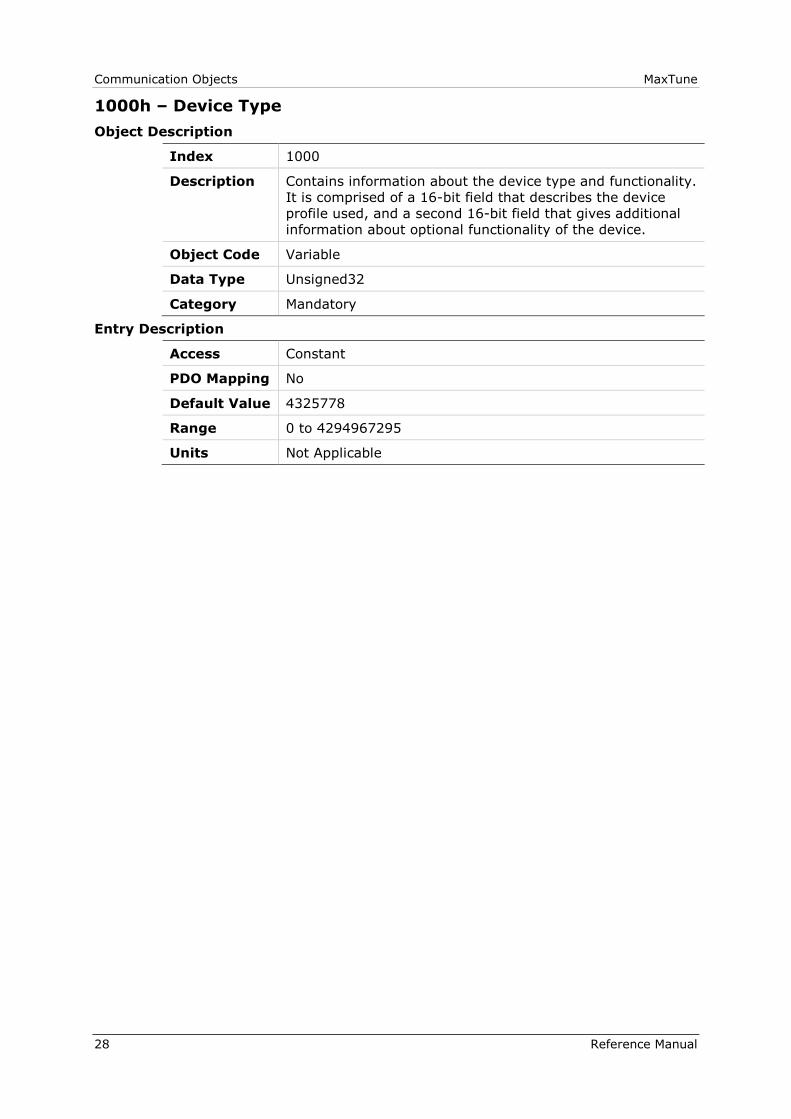
1000h – Device Type
Object Description
Index 1000
Description Contains information about the device type and functionality.
It is comprised of a 16-bit field that describes the device
profile used, and a second 16-bit field that gives additional
information about optional functionality of the device.
Object Code Variable
Data Type Unsigned32
Category Mandatory
Entry Description
Access Constant
PDO Mapping No
Default Value 4325778
Range 0 to 4294967295
Units Not Applicable

MaxTune Communication Objects
Reference Manual 29
1001h – Error Register
Object Description
Index 1001
Description An error register for the device.
A field of 8 bits, each of which indicates a particular type of
error. If a bit is set to 1, the specified error has occurred.
Bit Description
0 = Generic error
1 = Current
2 = Voltage
3 = Temperature
4 = Communication error (overrun, error state)
5 = Device profile specific
6 = Reserved
7 = Manufacturer specific
Object Code Variable
Data Type Unsigned8
Category Mandatory
Entry Description
Access Read Only
PDO Mapping No
Default Value 0
Range 0 to 255
Units Not Applicable
1002h – Manufacturer Status Register
Object Description
Index 1002
Description A common status register for manufacturer specific
purposes.
Object Code Variable
Data Type Unsigned32
Category Optional
Entry Description
Access Read Only
PDO Mapping No
Default Value 0
Range 0 to 4294967295
Units Not Applicable

Communication Objects MaxTune
30 Reference Manual
1003h – Predefined Error Field
Object Description
Index 1003
Description Holds errors that occurred in the device and have been
signaled via the Emergency object. It is an error history.
Object Code Array
Data Type Unsigned32
Category Optional
Entry Description
Sub-Index 000
Description Number of errors.
Contains the number of actual errors recorded in the array,
starting at sub-index 1. It can read 0 if no error is
registered, or 1 if an error is registered.
Writing a 0 to sub-index 0 deletes the entire error history.
Object Code Variable
Data Type Unsigned8
Category Mandatory
Access Read/Write
PDO Mapping No
Default Value 0
Range 0 to 254
Units Not Applicable
Sub-Index 001 – 002 – 003 – 004 – 005
006 – 007 – 008 – 009 – 010
Description Standard error field
Object Code Variable
Data Type Unsigned32
Category Mandatory
Access Read Only
PDO Mapping No
Default Value 0
Range 0 to 4294967295
Units Not Applicable

MaxTune Communication Objects
Reference Manual 31
1005h – COB-ID SYNC Message
Object Description
Index 1005
Description Defines the COB-ID of the synchronization object (SYNC).
The device generates a SYNC message if bit 30 is set.
The meaning of other bits is the same as for other
communication objects.
Object Code Variable
Data Type Unsigned32
Category Optional
Entry Description
Access Read/Write
PDO Mapping No
Default Value 2147483776
Range 1 to 4294967295
Units Not Applicable
1006h – Communication Cycle Period
Object Description
Index 1006
Description Defines the communication cycle period.
It is 0 if not used.
Object Code Variable
Data Type Unsigned32
Category Optional
Entry Description
Access Read/Write
PDO Mapping No
Default Value 500000
Range 0 to 4294967295
Units µs

Communication Objects MaxTune
32 Reference Manual
1007h – Synchronous Window Length
Object Description
Index 1007
Description Defines the length of the time window for synchronous
messages.
It is 0 if not used.
Object Code Variable
Data Type Unsigned32
Category Optional
Entry Description
Access Read/Write
PDO Mapping No
Default Value 0
Range 0 to 4294967295
Units µs
1008h – Manufacturer Device Name
Object Description
Index 1008
Description The manufacturer device name, such as “MaxTune drive”.
Object Code Variable
Data Type Visible_String
Category Optional
Entry Description
Access Constant
PDO Mapping No
Default Value MaxTune drive
Range Not Applicable
Units Not Applicable

MaxTune Communication Objects
Reference Manual 33
1009h – Manufacturer Hardware Version
Object Description
Index 1009
Description The version number of the manufacturer’s hardware.
Object Code Variable
Data Type Visible_String
Category Optional
Entry Description
Access Constant
PDO Mapping No
Default Value Control:00 Power:00
Range Not Applicable
Units Not Applicable
100Ah – Manufacturer Software Version
Object Description
Index 100A
Description The version number of the manufacturer’s software.
Object Code Variable
Data Type Visible_String
Category Optional
Entry Description
Access Constant
PDO Mapping No
Default Value 0.0.00
Range Not Applicable
Units Not Applicable

Communication Objects MaxTune
34 Reference Manual
1010h – Store Parameter Field
Object Description
Index 1010
Description Still in Development. Not intended for user unless
instructed by Technical Support.
Saves parameters in non-volatile memory.
Sub-index 1: All parameters
Sub-index 2: Communication parameters
Sub-index 3: Application parameters
Sub-index 4-127: Manufacturer defined parameters
Writing 65766173h (ASCII value of "save") to the
appropriate sub-index saves the parameters.
Object Code Array
Data Type Unsigned32
Category Optional
Entry Description
Sub-Index 000
Description Number of entries
Object Code Variable
Data Type Unsigned8
Category Optional
Access Read Only
PDO Mapping No
Default Value 3
Range 0 to 127
Units Not Applicable
Sub-Index 001
Description Saves all parameters
Object Code Variable
Data Type Unsigned32
Category Optional
Access Read/Write
PDO Mapping No
Default Value 0
Range 0 to 4294967295
Units Not Applicable

MaxTune Communication Objects
Reference Manual 35
Sub-Index 002
Description Saves communication parameters
Object Code Variable
Data Type Unsigned32
Category Optional
Access Read/Write
PDO Mapping No
Default Value 0
Range 0 to 4294967295
Units Not Applicable
Sub-Index 003
Description Saves application parameters
Object Code Variable
Data Type Unsigned32
Category Optional
Access Read/Write
PDO Mapping No
Default Value 0
Range 0 to 4294967295
Units Not Applicable

Communication Objects MaxTune
36 Reference Manual
1011h – Restore Default Parameters
Object Description
Index 1010
Description Still in Development. Not intended for user unless
instructed by Technical Support.
Loads all parameters from non-volatile memory.
Sub-index 1: All parameters
Sub-index 2: Communication parameters
Sub-index 3: Application parameters
Sub-index 4-127: Manufacturer defined parameters
Writing 64616F6Ch (ASCII value of "load") to the
appropriate sub-index restores the parameters.
Object Code Array
Data Type Unsigned32
Category Optional
Entry Description
Sub-Index 000
Description Number of entries
Object Code Variable
Data Type Unsigned8
Category Optional
Access Read Only
PDO Mapping No
Default Value 3
Range 0 to 127
Units Not Applicable
Sub-Index 001
Description Restores all default parameters
Object Code Variable
Data Type Unsigned32
Category Optional
Access Read/Write
PDO Mapping No
Default Value 0
Range 0 to 4294967295
Units Not Applicable
MaxTune Communication Objects
Reference Manual 37
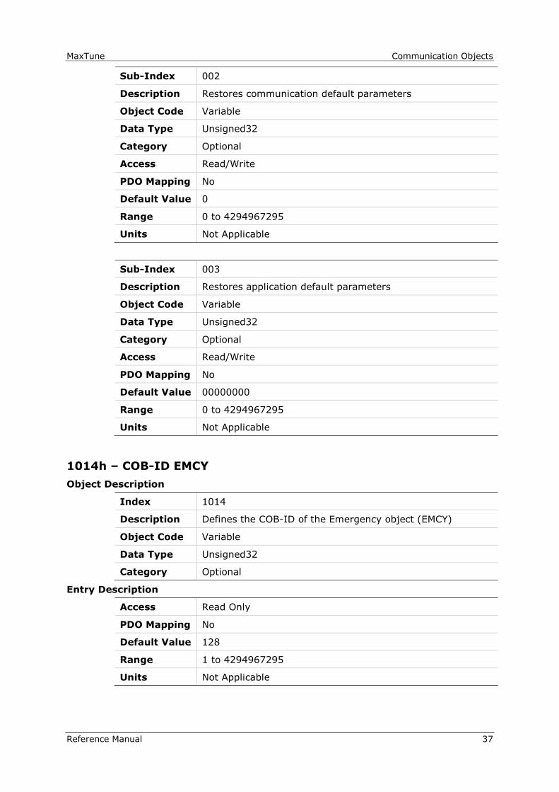
Sub-Index 002
Description Restores communication default parameters
Object Code Variable
Data Type Unsigned32
Category Optional
Access Read/Write
PDO Mapping No
Default Value 0
Range 0 to 4294967295
Units Not Applicable
Sub-Index 003
Description Restores application default parameters
Object Code Variable
Data Type Unsigned32
Category Optional
Access Read/Write
PDO Mapping No
Default Value 00000000
Range 0 to 4294967295
Units Not Applicable
1014h – COB-ID EMCY
Object Description
Index 1014
Description Defines the COB-ID of the Emergency object (EMCY)
Object Code Variable
Data Type Unsigned32
Category Optional
Entry Description
Access Read Only
PDO Mapping No
Default Value 128
Range 1 to 4294967295
Units Not Applicable
Communication Objects MaxTune
38 Reference Manual
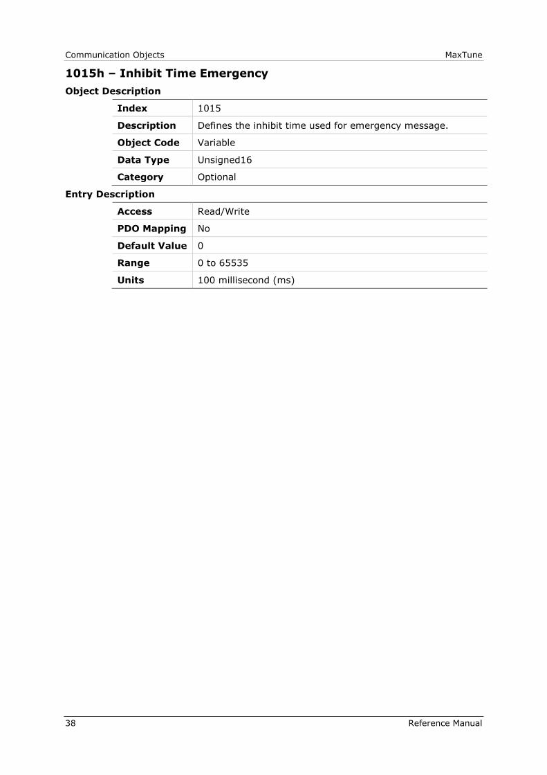
1015h – Inhibit Time Emergency
Object Description
Index 1015
Description Defines the inhibit time used for emergency message.
Object Code Variable
Data Type Unsigned16
Category Optional
Entry Description
Access Read/Write
PDO Mapping No
Default Value 0
Range 0 to 65535
Units 100 millisecond (ms)
MaxTune Communication Objects
Reference Manual 39
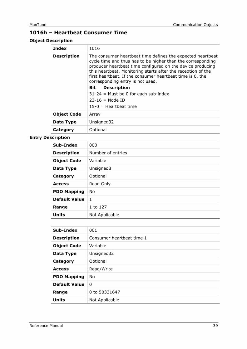
1016h – Heartbeat Consumer Time
Object Description
Index 1016
Description The consumer heartbeat time defines the expected heartbeat
cycle time and thus has to be higher than the corresponding
producer heartbeat time configured on the device producing
this heartbeat. Monitoring starts after the reception of the
first heartbeat. If the consumer heartbeat time is 0, the
corresponding entry is not used.
Bit Description
31-24 = Must be 0 for each sub-index
23-16 = Node ID
15-0 = Heartbeat time
Object Code Array
Data Type Unsigned32
Category Optional
Entry Description
Sub-Index 000
Description Number of entries
Object Code Variable
Data Type Unsigned8
Category Optional
Access Read Only
PDO Mapping No
Default Value 1
Range 1 to 127
Units Not Applicable
Sub-Index 001
Description Consumer heartbeat time 1
Object Code Variable
Data Type Unsigned32
Category Optional
Access Read/Write
PDO Mapping No
Default Value 0
Range 0 to 50331647
Units Not Applicable

Communication Objects MaxTune
40 Reference Manual
1017h – Producer Heartbeat Time
Object Description
Index 1017
Description This object defines the cycle time of the heartbeat, which
must be a multiple of 1 millisecond. It is 0 if not used.
Object Code Variable
Data Type Unsigned16
Category Optional
Entry Description
Access Read/Write
PDO Mapping No
Default Value 0
Range 0 to 65535
Units milliseconds (ms)
MaxTune Communication Objects
Reference Manual 41
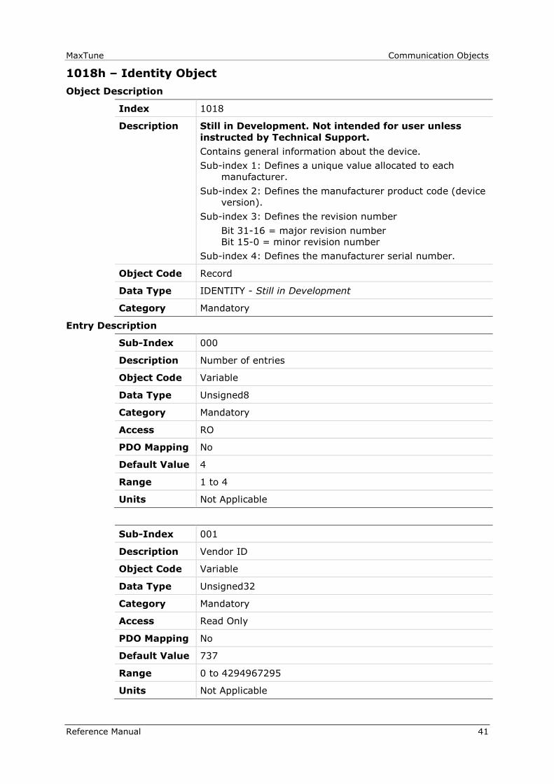
1018h – Identity Object
Object Description
Index 1018
Description Still in Development. Not intended for user unless
instructed by Technical Support.
Contains general information about the device.
Sub-index 1: Defines a unique value allocated to each
manufacturer.
Sub-index 2: Defines the manufacturer product code (device
version).
Sub-index 3: Defines the revision number
Bit 31-16 = major revision number
Bit 15-0 = minor revision number
Sub-index 4: Defines the manufacturer serial number.
Object Code Record
Data Type IDENTITY - Still in Development
Category Mandatory
Entry Description
Sub-Index 000
Description Number of entries
Object Code Variable
Data Type Unsigned8
Category Mandatory
Access RO
PDO Mapping No
Default Value 4
Range 1 to 4
Units Not Applicable
Sub-Index 001
Description Vendor ID
Object Code Variable
Data Type Unsigned32
Category Mandatory
Access Read Only
PDO Mapping No
Default Value 737
Range 0 to 4294967295
Units Not Applicable

Communication Objects MaxTune
42 Reference Manual
Sub-Index 002
Description Product code
Object Code Variable
Data Type Unsigned32
Category Optional
Access Read Only
PDO Mapping No
Default Value 1
Range 0 to 4294967295
Units Not Applicable
Sub-Index 003
Description Revision number
Object Code Variable
Data Type Unsigned32
Category Optional
Access Read Only
PDO Mapping No
Default Value 0
Range 0 to 4294967295
Units Not Applicable
Sub-Index 004
Description Serial number
Object Code Variable
Data Type Unsigned32
Category Optional
Access Read Only
PDO Mapping No
Default Value 0
Range 0 to 4294967295
Units Not Applicable

MaxTune Communication Objects
Reference Manual 43
1019h – Synchronous Counter Overflow Value
Object Description
Index 1019
Description Defines whether a counter is mapped into the SYNC
message, and the highest possible value of the counter.
0 = SYNC message transmitted with length 0
1 = Reserved
2..240 = SYNC message transmitted with length 1,
first data byte contains the counter value
241..255 = Reserved
Object Code Variable
Data Type Unsigned8
Category Optional
Entry Description
Access Read/Write
PDO Mapping No
Default Value 0
Range 0 to 240
Units Not Applicable
Communication Objects MaxTune
44 Reference Manual
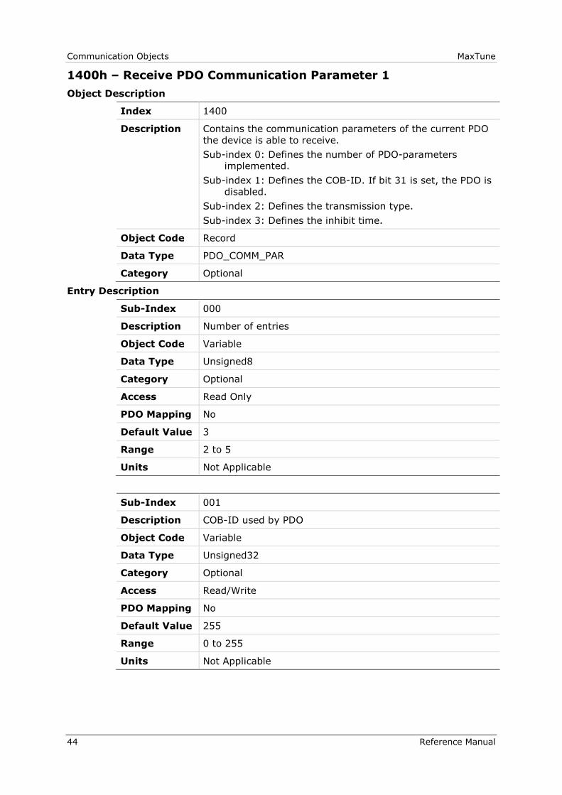
1400h – Receive PDO Communication Parameter 1
Object Description
Index 1400
Description Contains the communication parameters of the current PDO
the device is able to receive.
Sub-index 0: Defines the number of PDO-parameters
implemented.
Sub-index 1: Defines the COB-ID. If bit 31 is set, the PDO is
disabled.
Sub-index 2: Defines the transmission type.
Sub-index 3: Defines the inhibit time.
Object Code Record
Data Type PDO_COMM_PAR
Category Optional
Entry Description
Sub-Index 000
Description Number of entries
Object Code Variable
Data Type Unsigned8
Category Optional
Access Read Only
PDO Mapping No
Default Value 3
Range 2 to 5
Units Not Applicable
Sub-Index 001
Description COB-ID used by PDO
Object Code Variable
Data Type Unsigned32
Category Optional
Access Read/Write
PDO Mapping No
Default Value 255
Range 0 to 255
Units Not Applicable

MaxTune Communication Objects
Reference Manual 45
Sub-Index 002
Description Transmission type
Object Code Variable
Data Type Unsigned8
Category Optional
Access Read/Write
PDO Mapping No
Default Value 255
Range 0 to 255
Units Not Applicable
Sub-Index 003
Description Inhibit time
Object Code Variable
Data Type Unsigned16
Category Optional
Access Read/Write
PDO Mapping No
Default Value 0
Range 0 to 255
Units 100 µs
Communication Objects MaxTune
46 Reference Manual
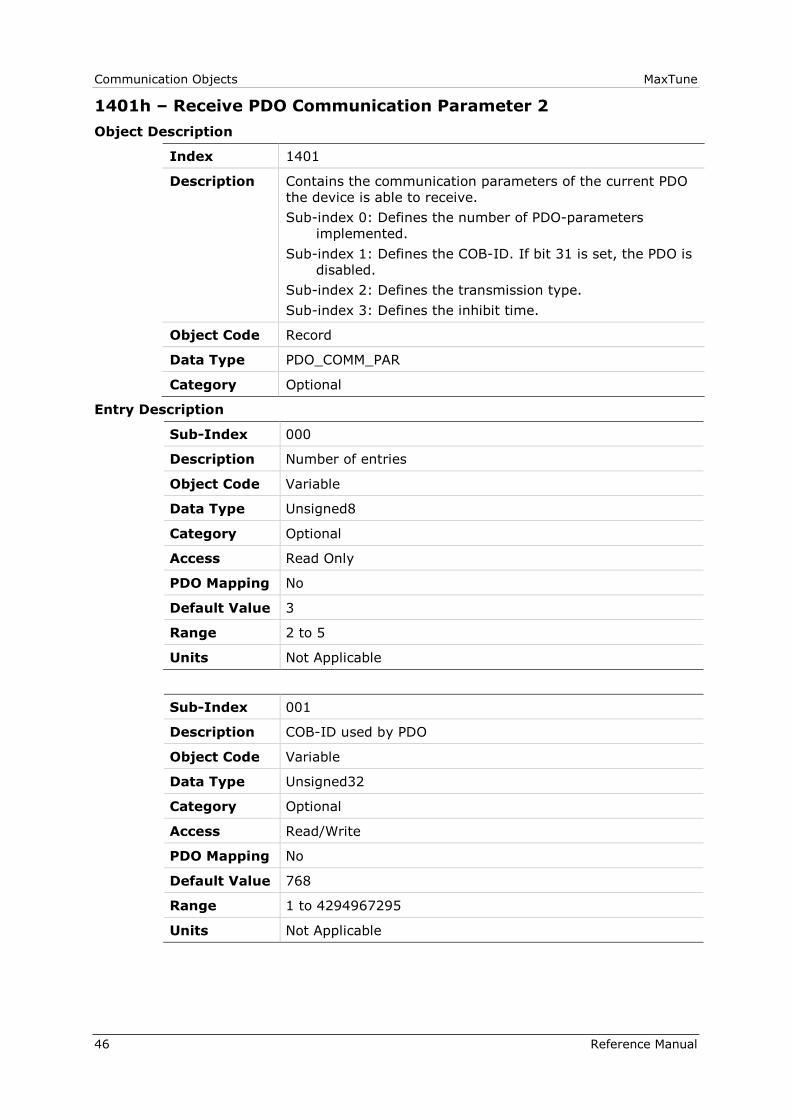
1401h – Receive PDO Communication Parameter 2
Object Description
Index 1401
Description Contains the communication parameters of the current PDO
the device is able to receive.
Sub-index 0: Defines the number of PDO-parameters
implemented.
Sub-index 1: Defines the COB-ID. If bit 31 is set, the PDO is
disabled.
Sub-index 2: Defines the transmission type.
Sub-index 3: Defines the inhibit time.
Object Code Record
Data Type PDO_COMM_PAR
Category Optional
Entry Description
Sub-Index 000
Description Number of entries
Object Code Variable
Data Type Unsigned8
Category Optional
Access Read Only
PDO Mapping No
Default Value 3
Range 2 to 5
Units Not Applicable
Sub-Index 001
Description COB-ID used by PDO
Object Code Variable
Data Type Unsigned32
Category Optional
Access Read/Write
PDO Mapping No
Default Value 768
Range 1 to 4294967295
Units Not Applicable

MaxTune Communication Objects
Reference Manual 47
Sub-Index 002
Description Transmission Type
Object Code Variable
Data Type Unsigned8
Category Optional
Access Read/Write
PDO Mapping No
Default Value 255
Range 0 to 255
Units Not Applicable
Sub-Index 003
Description Inhibit Time
Object Code Variable
Data Type Unsigned16
Category Optional
Access Read/Write
PDO Mapping No
Default Value 0
Range 0 to 65535
Units 100 µs

Communication Objects MaxTune
48 Reference Manual
1402h – Receive PDO Communication Parameter 3
Object Description
Index 1402
Description Contains the communication parameters of the current PDO
the device is able to receive.
Sub-index 0: Defines the number of PDO-parameters
implemented.
Sub-index 1: Defines the COB-ID. If bit 31 is set, the PDO is
disabled.
Sub-index 2: Defines the transmission type.
Sub-index 3: Defines the inhibit time.
Object Code Record
Data Type PDO_COMM_PAR
Category Optional
Entry Description
Sub-Index 000
Description Number of entries
Object Code Variable
Data Type Unsigned8
Category Optional
Access Read Only
PDO Mapping No
Default Value 3
Range 2 to 5
Units Not Applicable
Sub-Index 001
Description COB-ID used by PDO
Object Code Variable
Data Type Unsigned32
Category Optional
Access Read/Write
PDO Mapping No
Default Value 1024
Range 1 to 4294967295
Units Not Applicable

MaxTune Communication Objects
Reference Manual 49
Sub-Index 002
Description Transmission Type
Object Code Variable
Data Type Unsigned8
Category Optional
Access Read/Write
PDO Mapping No
Default Value 255
Range 0 to 255
Units Not Applicable
Sub-Index 003
Description Inhibit Time
Object Code Variable
Data Type Unsigned16
Category Optional
Access Read/Write
PDO Mapping No
Default Value 0
Range 0 to 65535

Communication Objects MaxTune
50 Reference Manual
1403h – Receive PDO Communication Parameter 4
Object Description
Index 1403
Description Contains the communication parameters of the current PDO
the device is able to receive.
Sub-index 0: Defines the number of PDO-parameters
implemented.
Sub-index 1: Defines the COB-ID. If bit 31 is set, the PDO is
disabled.
Sub-index 2: Defines the transmission type.
Sub-index 3: Defines the inhibit time.
Object Code Record
Data Type PDO_COMM_PAR
Category Optional
Entry Description
Sub-Index 000
Description Number of entries
Object Code Variable
Data Type Unsigned8
Category Optional
Access Read Only
PDO Mapping No
Default Value 3
Range 2 to 5
Units Not Applicable
Sub-Index 001
Description COB-ID used by PDO
Object Code Variable
Data Type Unsigned32
Category Optional
Access Read/Write
PDO Mapping No
Default Value 1280
Range 1 to 4294967295
Units Not Applicable
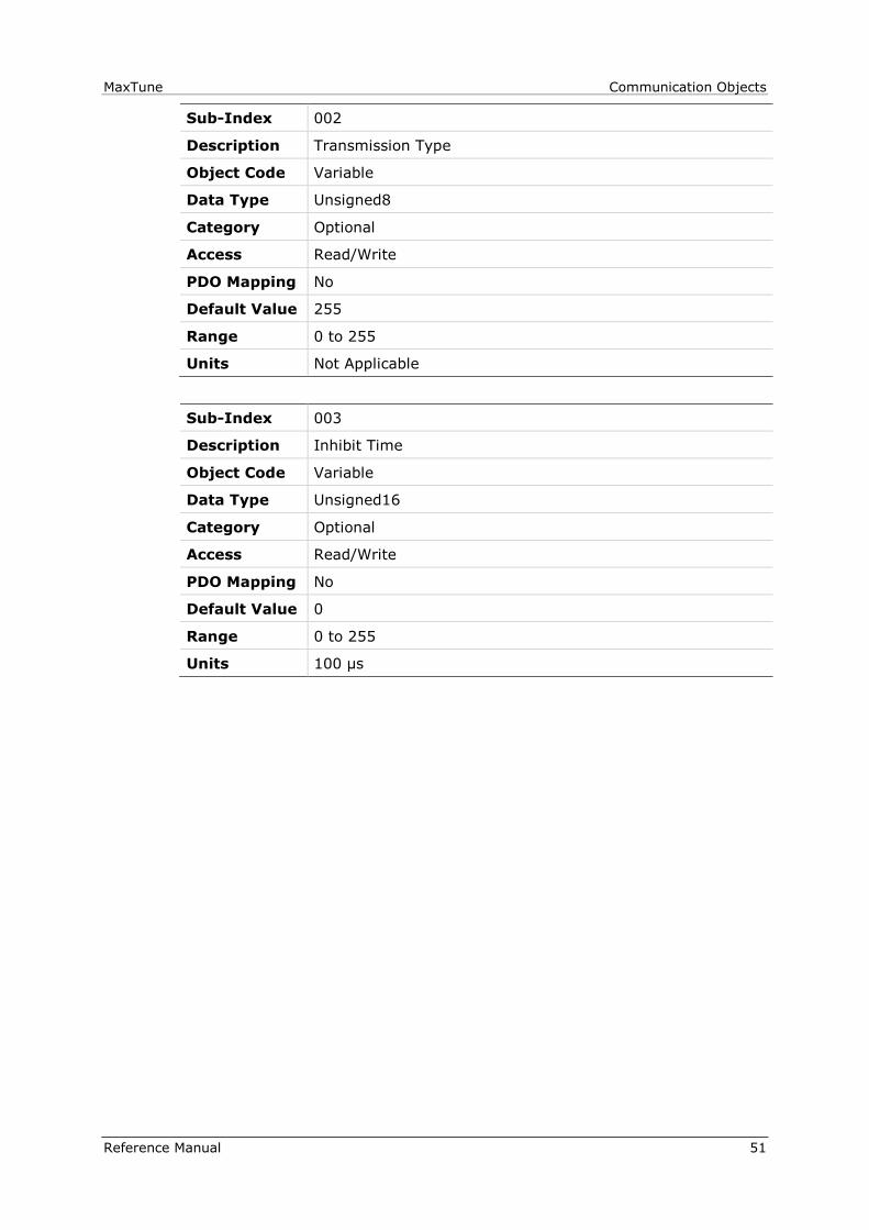
MaxTune Communication Objects
Reference Manual 51
Sub-Index 002
Description Transmission Type
Object Code Variable
Data Type Unsigned8
Category Optional
Access Read/Write
PDO Mapping No
Default Value 255
Range 0 to 255
Units Not Applicable
Sub-Index 003
Description Inhibit Time
Object Code Variable
Data Type Unsigned16
Category Optional
Access Read/Write
PDO Mapping No
Default Value 0
Range 0 to 255
Units 100 µs
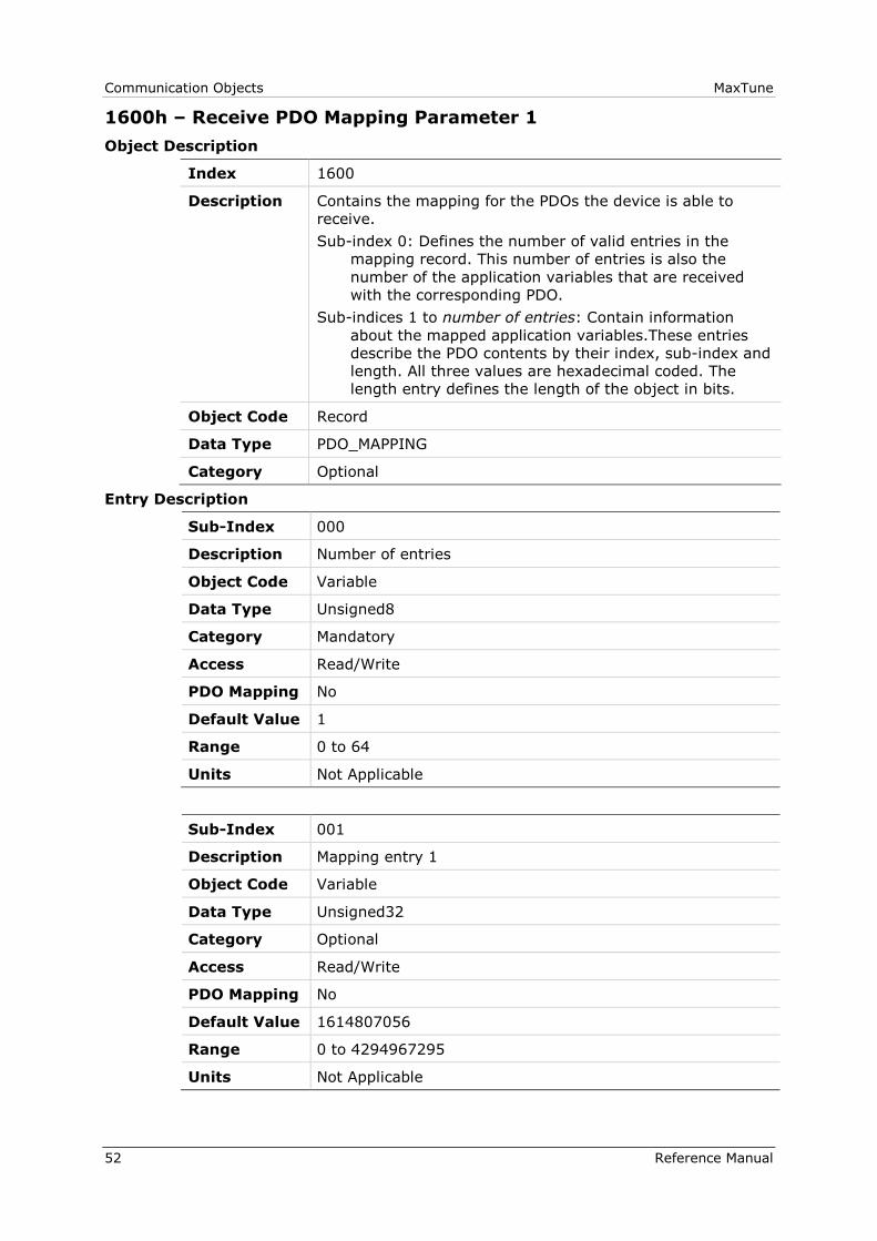
Communication Objects MaxTune
52 Reference Manual
1600h – Receive PDO Mapping Parameter 1
Object Description
Index 1600
Description Contains the mapping for the PDOs the device is able to
receive.
Sub-index 0: Defines the number of valid entries in the
mapping record. This number of entries is also the
number of the application variables that are received
with the corresponding PDO.
Sub-indices 1 to number of entries: Contain information
about the mapped application variables.These entries
describe the PDO contents by their index, sub-index and
length. All three values are hexadecimal coded. The
length entry defines the length of the object in bits.
Object Code Record
Data Type PDO_MAPPING
Category Optional
Entry Description
Sub-Index 000
Description Number of entries
Object Code Variable
Data Type Unsigned8
Category Mandatory
Access Read/Write
PDO Mapping No
Default Value 1
Range 0 to 64
Units Not Applicable
Sub-Index 001
Description Mapping entry 1
Object Code Variable
Data Type Unsigned32
Category Optional
Access Read/Write
PDO Mapping No
Default Value 1614807056
Range 0 to 4294967295
Units Not Applicable
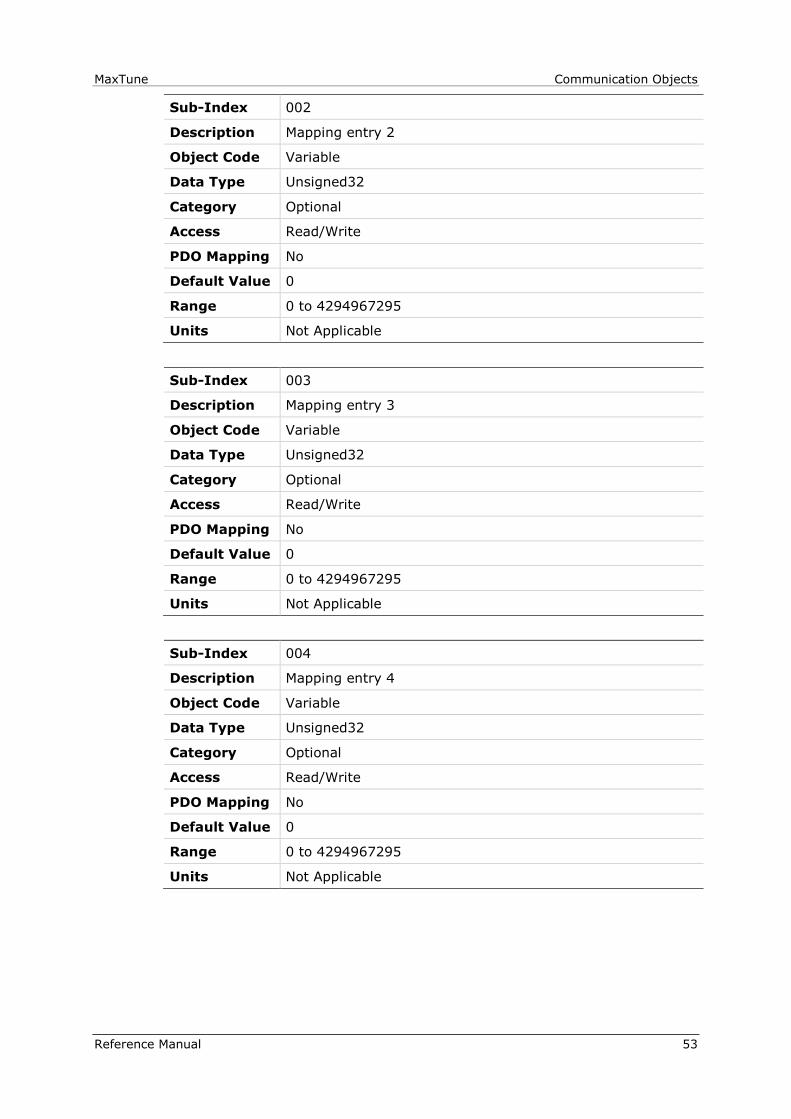
MaxTune Communication Objects
Reference Manual 53
Sub-Index 002
Description Mapping entry 2
Object Code Variable
Data Type Unsigned32
Category Optional
Access Read/Write
PDO Mapping No
Default Value 0
Range 0 to 4294967295
Units Not Applicable
Sub-Index 003
Description Mapping entry 3
Object Code Variable
Data Type Unsigned32
Category Optional
Access Read/Write
PDO Mapping No
Default Value 0
Range 0 to 4294967295
Units Not Applicable
Sub-Index 004
Description Mapping entry 4
Object Code Variable
Data Type Unsigned32
Category Optional
Access Read/Write
PDO Mapping No
Default Value 0
Range 0 to 4294967295
Units Not Applicable

Communication Objects MaxTune
54 Reference Manual
1601h – Receive PDO Mapping Parameter 2
Object Description
Index 1601
Description Contains the mapping for the PDOs the device is able to
receive.
Sub-index 0: Defines the number of valid entries in the
mapping record. This number of entries is also the
number of the application variables that are received
with the corresponding PDO.
Sub-indices 1 to number of entries: Contain information
about the mapped application variables.
These entries describe the PDO contents by their index,
sub-index and length. All three values are hexadecimal
coded. The length entry defines the length of the object
in bits.
This parameter can be used to verify the overall mapping
length. It is mandatory.
Object Code Record
Data Type PDO_MAPPING
Category Optional
Entry Description
Sub-Index 000
Description Number of entries
Object Code Variable
Data Type Unsigned8
Category Mandatory
Access Read/Write
PDO Mapping No
Default Value 2
Range 0 to 64
Units Not Applicable
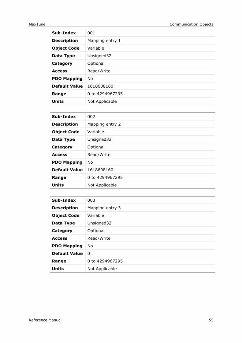
MaxTune Communication Objects
Reference Manual 55
Sub-Index 001
Description Mapping entry 1
Object Code Variable
Data Type Unsigned32
Category Optional
Access Read/Write
PDO Mapping No
Default Value 1618608160
Range 0 to 4294967295
Units Not Applicable
Sub-Index 002
Description Mapping entry 2
Object Code Variable
Data Type Unsigned32
Category Optional
Access Read/Write
PDO Mapping No
Default Value 1618608160
Range 0 to 4294967295
Units Not Applicable
Sub-Index 003
Description Mapping entry 3
Object Code Variable
Data Type Unsigned32
Category Optional
Access Read/Write
PDO Mapping No
Default Value 0
Range 0 to 4294967295
Units Not Applicable

Communication Objects MaxTune
56 Reference Manual
Sub-Index 004
Description Mapping entry 4
Object Code Variable
Data Type Unsigned32
Category Optional
Access Read/Write
PDO Mapping No
Default Value 0
Range 0 to 4294967295
Units Not Applicable
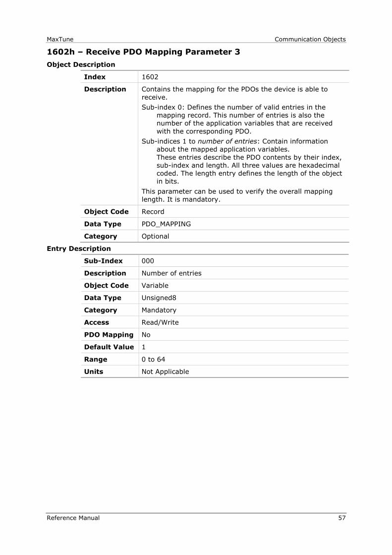
MaxTune Communication Objects
Reference Manual 57
1602h – Receive PDO Mapping Parameter 3
Object Description
Index 1602
Description Contains the mapping for the PDOs the device is able to
receive.
Sub-index 0: Defines the number of valid entries in the
mapping record. This number of entries is also the
number of the application variables that are received
with the corresponding PDO.
Sub-indices 1 to number of entries: Contain information
about the mapped application variables.
These entries describe the PDO contents by their index,
sub-index and length. All three values are hexadecimal
coded. The length entry defines the length of the object
in bits.
This parameter can be used to verify the overall mapping
length. It is mandatory.
Object Code Record
Data Type PDO_MAPPING
Category Optional
Entry Description
Sub-Index 000
Description Number of entries
Object Code Variable
Data Type Unsigned8
Category Mandatory
Access Read/Write
PDO Mapping No
Default Value 1
Range 0 to 64
Units Not Applicable

Communication Objects MaxTune
58 Reference Manual
Sub-Index 001
Description Mapping entry 1
Object Code Variable
Data Type Unsigned32
Category Optional
Access Read/Write
PDO Mapping No
Default Value 1627324448
Range 0 to 4294967295
Units Not Applicable
Sub-Index 002
Description Mapping entry 2
Object Code Variable
Data Type Unsigned32
Category Optional
Access Read/Write
PDO Mapping No
Default Value 0
Range 0 to 4294967295
Units Not Applicable
Sub-Index 003
Description Mapping entry 3
Object Code Variable
Data Type Unsigned32
Category Optional
Access Read/Write
PDO Mapping No
Default Value 0
Range 0 to 4294967295
Units Not Applicable

MaxTune Communication Objects
Reference Manual 59
Sub-Index 004
Description Mapping entry 4
Object Code Variable
Data Type Unsigned32
Category Optional
Access Read/Write
PDO Mapping No
Default Value 0
Range 0 to 4294967295
Units Not Applicable

Communication Objects MaxTune
60 Reference Manual
1603h – Receive PDO Mapping Parameter 4
Object Description
Index 1603
Description Contains the mapping for the PDOs the device is able to
receive.
Sub-index 0: Defines the number of valid entries in the
mapping record. This number of entries is also the
number of the application variables that are received
with the corresponding PDO.
Sub-indices 1 to number of entries: Contain information
about the mapped application variables.
These entries describe the PDO contents by their index,
sub-index and length. All three values are hexadecimal
coded. The length entry defines the length of the object
in bits.
This parameter can be used to verify the overall mapping
length. It is mandatory.
Object Code Record
Data Type PDO_MAPPING
Category Optional
Entry Description
Sub-Index 000
Description Number of entries
Object Code Variable
Data Type Unsigned8
Category Mandatory
Access Read/Write
PDO Mapping No
Default Value 1
Range 0 to 64
Units Not Applicable

MaxTune Communication Objects
Reference Manual 61
Sub-Index 001
Description Mapping entry 1
Object Code Variable
Data Type Unsigned32
Category Optional
Access Read/Write
PDO Mapping No
Default Value 1618018320
Range 0 to 4294967295
Units Not Applicable
Sub-Index 002
Description Mapping entry 2
Object Code Variable
Data Type Unsigned32
Category Optional
Access Read/Write
PDO Mapping No
Default Value 0
Range 0 to 4294967295
Units Not Applicable
Sub-Index 003
Description Mapping entry 3
Object Code Variable
Data Type Unsigned32
Category Optional
Access Read/Write
PDO Mapping No
Default Value 0
Range 0 to 4294967295
Units Not Applicable

Communication Objects MaxTune
62 Reference Manual
Sub-Index 004
Description Mapping entry 4
Object Code Variable
Data Type Unsigned32
Category Optional
Access Read/Write
PDO Mapping No
Default Value 0
Range 0 to 4294967295
Units Not Applicable
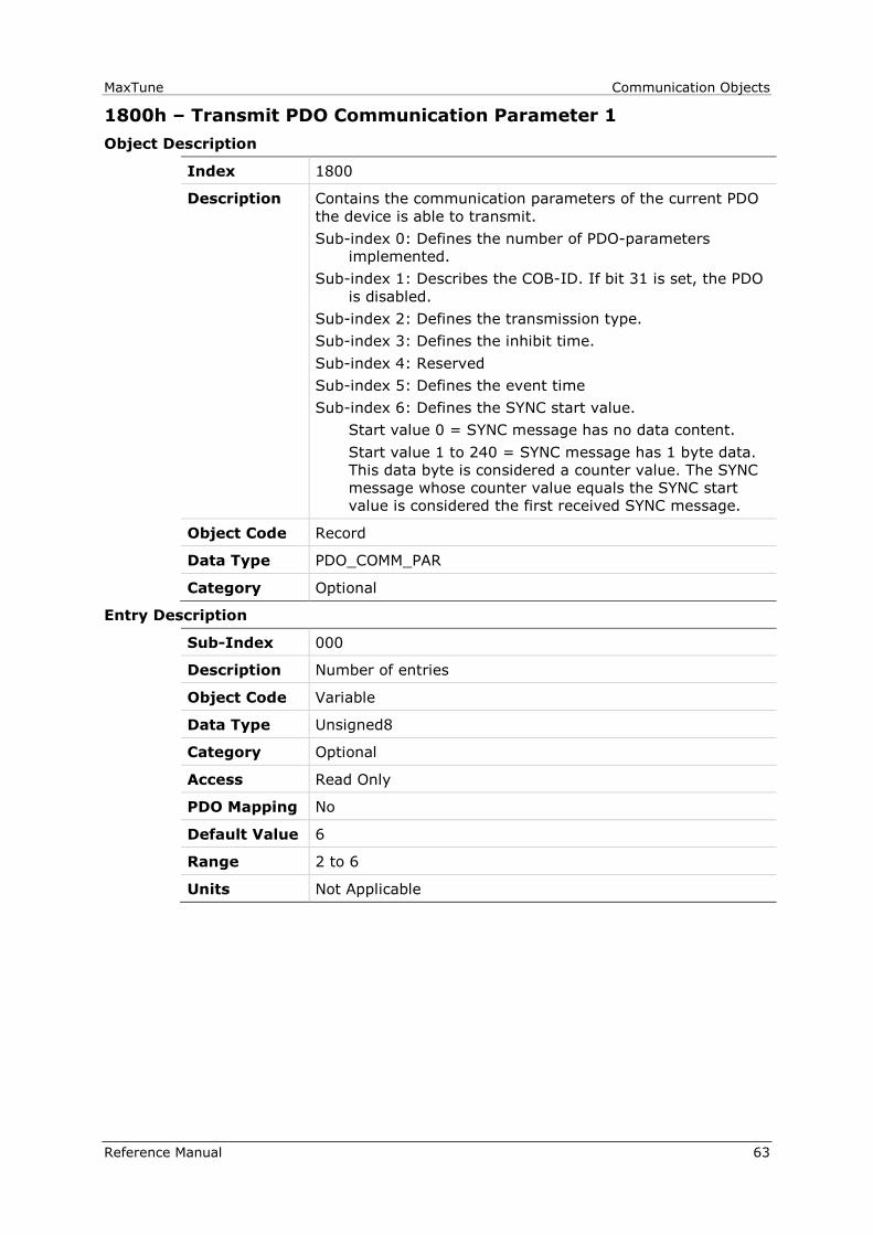
MaxTune Communication Objects
Reference Manual 63
1800h – Transmit PDO Communication Parameter 1
Object Description
Index 1800
Description Contains the communication parameters of the current PDO
the device is able to transmit.
Sub-index 0: Defines the number of PDO-parameters
implemented.
Sub-index 1: Describes the COB-ID. If bit 31 is set, the PDO
is disabled.
Sub-index 2: Defines the transmission type.
Sub-index 3: Defines the inhibit time.
Sub-index 4: Reserved
Sub-index 5: Defines the event time
Sub-index 6: Defines the SYNC start value.
Start value 0 = SYNC message has no data content.
Start value 1 to 240 = SYNC message has 1 byte data.
This data byte is considered a counter value. The SYNC
message whose counter value equals the SYNC start
value is considered the first received SYNC message.
Object Code Record
Data Type PDO_COMM_PAR
Category Optional
Entry Description
Sub-Index 000
Description Number of entries
Object Code Variable
Data Type Unsigned8
Category Optional
Access Read Only
PDO Mapping No
Default Value 6
Range 2 to 6
Units Not Applicable
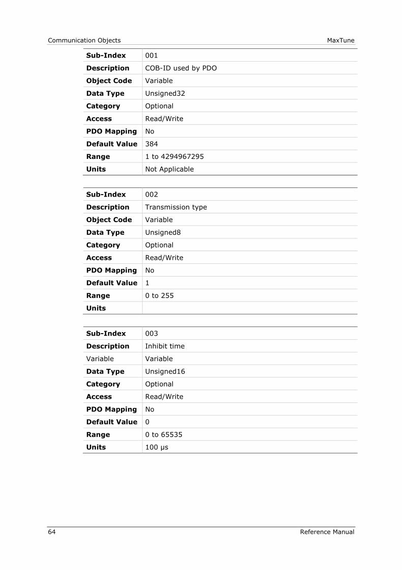
Communication Objects MaxTune
64 Reference Manual
Sub-Index 001
Description COB-ID used by PDO
Object Code Variable
Data Type Unsigned32
Category Optional
Access Read/Write
PDO Mapping No
Default Value 384
Range 1 to 4294967295
Units Not Applicable
Sub-Index 002
Description Transmission type
Object Code Variable
Data Type Unsigned8
Category Optional
Access Read/Write
PDO Mapping No
Default Value 1
Range 0 to 255
Units
Sub-Index 003
Description Inhibit time
Variable Variable
Data Type Unsigned16
Category Optional
Access Read/Write
PDO Mapping No
Default Value 0
Range 0 to 65535
Units 100 µs

MaxTune Communication Objects
Reference Manual 65
Sub-Index 004
Description Compatibility entry
Object Code Variable
Data Type Unsigned8
Category Optional
Access Read/Write
PDO Mapping No
Default Value 0
Range 0 to 255
Units Not Applicable
Sub-Index 005
Description Event timer
Object Code Variable
Data Type Unsigned16
Category Optional
Access Read/Write
PDO Mapping No
Default Value 0
Range 0 to 65535
Units ms
Sub-Index 006
Description Sync start value
Object Code Variable
Data Type Unsigned8
Category Optional
Access Read/Write
PDO Mapping No
Default Value 0
Range 0 to 255
Units Not Applicable

Communication Objects MaxTune
66 Reference Manual
1801h – Transmit PDO Communication Parameter 2
Object Description
Index 1801
Description Contains the communication parameters of the current PDO
the device is able to transmit.
Sub-index 0: Defines the number of PDO-parameters
implemented.
Sub-index 1: Describes the COB-ID. If bit 31 is set, the PDO
is disabled.
Sub-index 2: Defines the transmission type.
Sub-index 3: Defines the inhibit time.
Sub-index 4: Reserved
Sub-index 5: Defines the event time
Sub-index 6: Defines the SYNC start value.
Start value 0 = SYNC message has no data content.
Start value 1 to 240 = SYNC message has 1 byte data.
This data byte is considered a counter value. The SYNC
message whose counter value equals the SYNC start
value is considered the first received SYNC message.
Object Code Record
Data Type PDO_COMM_PAR
Category Optional
Entry Description
Sub-Index 000
Description Number of entries
Object Code Variable
Data Type Unsigned8
Category Optional
Access Read Only
PDO Mapping No
Default Value 6
Range 2 to 6
Units Not Applicable

MaxTune Communication Objects
Reference Manual 67
Sub-Index 001
Description COB-ID used by PDO
Object Code Variable
Data Type Unsigned32
Category Optional
Access Read/Write
PDO Mapping No
Default Value 640
Range 1 to 4294967295
Units Not Applicable
Sub-Index 002
Description Transmission Type
Object Code Variable
Data Type Unsigned8
Category Optional
Access Read/Write
PDO Mapping No
Default Value 1
Range 0 to 255
Units Not Applicable
Sub-Index 003
Description Inhibit Time
Variable Variable
Data Type Unsigned16
Category Optional
Access Read/Write
PDO Mapping No
Default Value 0
Range 0 to 65535
Units 100 µs

Communication Objects MaxTune
68 Reference Manual
Sub-Index 004
Description Compatibility Entry
Object Code Variable
Data Type Unsigned8
Category Optional
Access Read/Write
PDO Mapping No
Default Value 0
Range 0 to 255
Units Not Applicable
Sub-Index 005
Description Event Timer
Object Code Variable
Data Type Unsigned16
Category Optional
Access Read/Write
PDO Mapping No
Default Value 0
Range 0 to 65535
Units ms
Sub-Index 006
Description Sync start value
Object Code Variable
Data Type Unsigned8
Category Optional
Access Read/Write
PDO Mapping No
Default Value 0
Range 0 to 255
Units Not Applicable

MaxTune Communication Objects
Reference Manual 69
1802h – Transmit PDO Communication Parameter 3
Object Description
Index 1802
Description Contains the communication parameters of the current PDO
the device is able to transmit.
Sub-index 0: Defines the number of PDO-parameters
implemented.
Sub-index 1: Describes the COB-ID. If bit 31 is set, the PDO
is disabled.
Sub-index 2: Defines the transmission type.
Sub-index 3: Defines the inhibit time.
Sub-index 4: Reserved
Sub-index 5: Defines the event time
Sub-index 6: Defines the SYNC start value.
Start value 0 = SYNC message has no data content.
Start value 1 to 240 = SYNC message has 1 byte data.
This data byte is considered a counter value. The SYNC
message whose counter value equals the SYNC start
value is considered the first received SYNC message.
Object Code Record
Data Type PDO_COMM_PAR
Category Optional
Entry Description
Sub-Index 000
Description Number of entries
Object Code Variable
Data Type Unsigned8
Category Optional
Access Read Only
PDO Mapping No
Default Value 6
Range 2 to 6
Units Not Applicable

Communication Objects MaxTune
70 Reference Manual
Sub-Index 001
Description COB-ID used by PDO
Object Code Variable
Data Type Unsigned32
Category Optional
Access Read/Write
PDO Mapping No
Default Value 896
Range 1 to 4294967295
Units Not Applicable
Sub-Index 002
Description Transmission type
Object Code Variable
Data Type Unsigned8
Category Optional
Access Read/Write
PDO Mapping No
Default Value 1
Range 0 to 255
Units Not Applicable
Sub-Index 003
Description Inhibit time
Variable Variable
Data Type Unsigned16
Category Optional
Access Read/Write
PDO Mapping No
Default Value 0
Range 0 to 65535
Units 100 µs
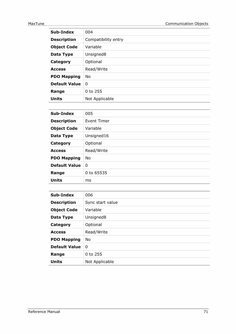
MaxTune Communication Objects
Reference Manual 71
Sub-Index 004
Description Compatibility entry
Object Code Variable
Data Type Unsigned8
Category Optional
Access Read/Write
PDO Mapping No
Default Value 0
Range 0 to 255
Units Not Applicable
Sub-Index 005
Description Event Timer
Object Code Variable
Data Type Unsigned16
Category Optional
Access Read/Write
PDO Mapping No
Default Value 0
Range 0 to 65535
Units ms
Sub-Index 006
Description Sync start value
Object Code Variable
Data Type Unsigned8
Category Optional
Access Read/Write
PDO Mapping No
Default Value 0
Range 0 to 255
Units Not Applicable
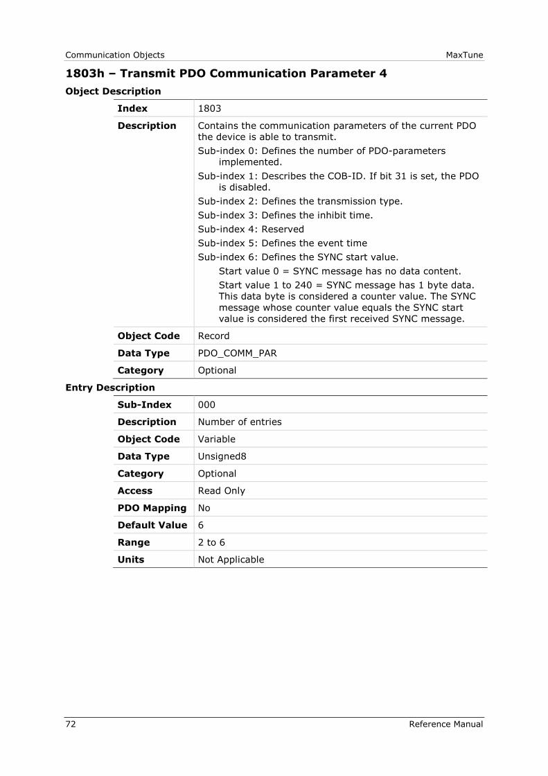
Communication Objects MaxTune
72 Reference Manual
1803h – Transmit PDO Communication Parameter 4
Object Description
Index 1803
Description Contains the communication parameters of the current PDO
the device is able to transmit.
Sub-index 0: Defines the number of PDO-parameters
implemented.
Sub-index 1: Describes the COB-ID. If bit 31 is set, the PDO
is disabled.
Sub-index 2: Defines the transmission type.
Sub-index 3: Defines the inhibit time.
Sub-index 4: Reserved
Sub-index 5: Defines the event time
Sub-index 6: Defines the SYNC start value.
Start value 0 = SYNC message has no data content.
Start value 1 to 240 = SYNC message has 1 byte data.
This data byte is considered a counter value. The SYNC
message whose counter value equals the SYNC start
value is considered the first received SYNC message.
Object Code Record
Data Type PDO_COMM_PAR
Category Optional
Entry Description
Sub-Index 000
Description Number of entries
Object Code Variable
Data Type Unsigned8
Category Optional
Access Read Only
PDO Mapping No
Default Value 6
Range 2 to 6
Units Not Applicable
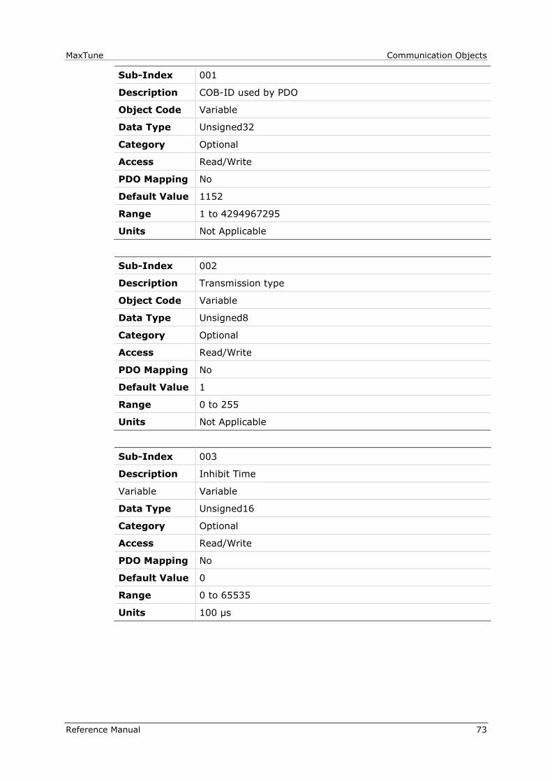
MaxTune Communication Objects
Reference Manual 73
Sub-Index 001
Description COB-ID used by PDO
Object Code Variable
Data Type Unsigned32
Category Optional
Access Read/Write
PDO Mapping No
Default Value 1152
Range 1 to 4294967295
Units Not Applicable
Sub-Index 002
Description Transmission type
Object Code Variable
Data Type Unsigned8
Category Optional
Access Read/Write
PDO Mapping No
Default Value 1
Range 0 to 255
Units Not Applicable
Sub-Index 003
Description Inhibit Time
Variable Variable
Data Type Unsigned16
Category Optional
Access Read/Write
PDO Mapping No
Default Value 0
Range 0 to 65535
Units 100 µs
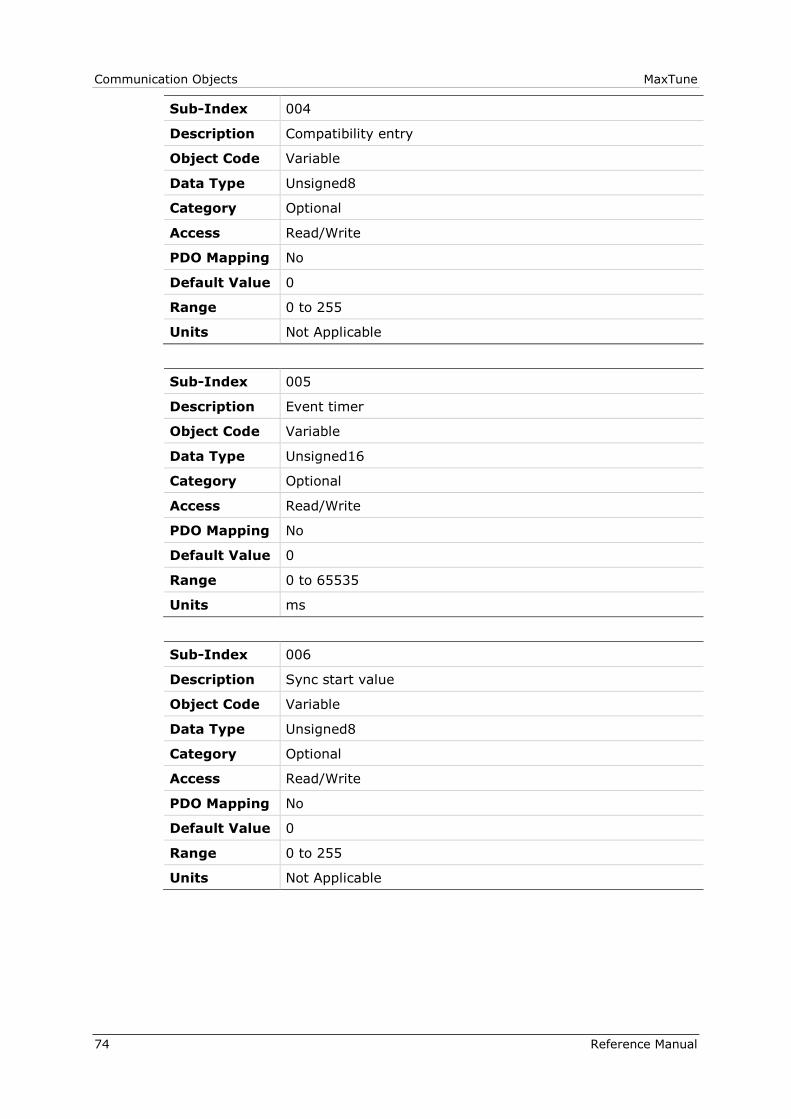
Communication Objects MaxTune
74 Reference Manual
Sub-Index 004
Description Compatibility entry
Object Code Variable
Data Type Unsigned8
Category Optional
Access Read/Write
PDO Mapping No
Default Value 0
Range 0 to 255
Units Not Applicable
Sub-Index 005
Description Event timer
Object Code Variable
Data Type Unsigned16
Category Optional
Access Read/Write
PDO Mapping No
Default Value 0
Range 0 to 65535
Units ms
Sub-Index 006
Description Sync start value
Object Code Variable
Data Type Unsigned8
Category Optional
Access Read/Write
PDO Mapping No
Default Value 0
Range 0 to 255
Units Not Applicable

MaxTune Communication Objects
Reference Manual 75
1A00h – Transmit PDO Mapping Parameter 1
Object Description
Index 1A00
Description Contains the mapping for the PDOs the device is able to
transmit.
Sub-index 0: Defines the number of valid entries in the
mapping record. This number of entries is also the
number of the application variables that are transmitted
with the corresponding PDO.
Sub-indices 1 to number of entries: Contain information
about the mapped application variables.
These entries describe the PDO contents by their index,
sub-index and length. All three values are hexadecimal
coded. The length entry defines the length of the object
in bits.
This parameter can be used to verify the overall mapping
length. It is mandatory.
Object Code Record
Data Type PDO_MAPPING
Category Optional
Entry Description
Sub-Index 000
Description Number of entries
Object Code Variable
Data Type Unsigned8
Category Mandatory
Access Read/Write
PDO Mapping No
Default Value 1
Range 0 to 255
Units Not Applicable

Communication Objects MaxTune
76 Reference Manual
Sub-Index 001
Description Mapping entry 1
Object Code Variable
Data Type Unsigned32
Category Optional
Access Read/Write
PDO Mapping No
Default Value 1614872592
Range 0 to 4294967295
Units Not Applicable
Sub-Index 002
Description Mapping entry 2
Object Code Variable
Data Type Unsigned32
Category Optional
Access Read/Write
PDO Mapping No
Default Value 0
Range 0 to 4294967295
Units Not Applicable
Sub-Index 003
Description Mapping entry 3
Object Code Variable
Data Type Unsigned32
Category Optional
Access Read/Write
PDO Mapping No
Default Value 0
Range 0 to 4294967295
Units Not Applicable

MaxTune Communication Objects
Reference Manual 77
Sub-Index 004
Description Mapping entry 4
Object Code Variable
Data Type Unsigned32
Category Optional
Access Read/Write
PDO Mapping No
Default Value 0
Range 0 to 4294967295
Units Not Applicable
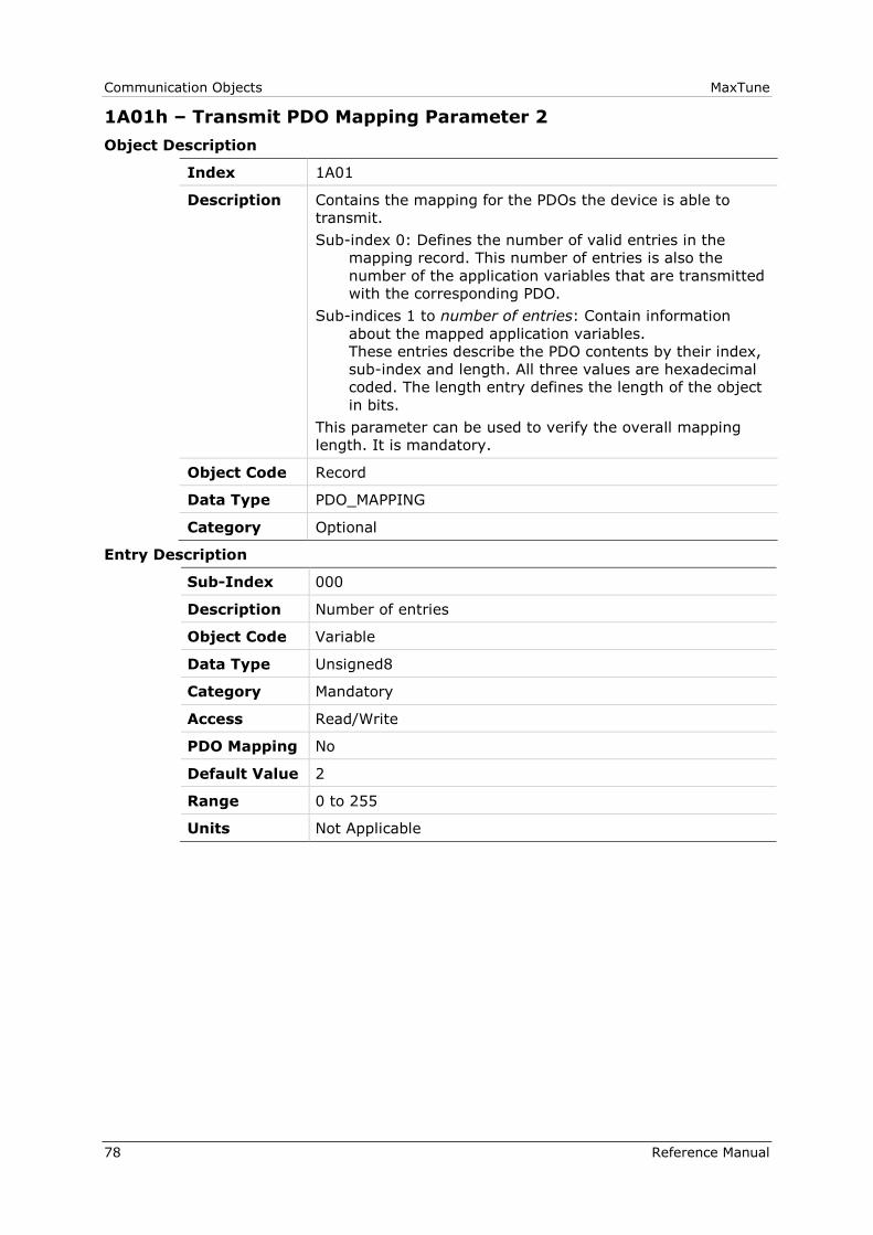
Communication Objects MaxTune
78 Reference Manual
1A01h – Transmit PDO Mapping Parameter 2
Object Description
Index 1A01
Description Contains the mapping for the PDOs the device is able to
transmit.
Sub-index 0: Defines the number of valid entries in the
mapping record. This number of entries is also the
number of the application variables that are transmitted
with the corresponding PDO.
Sub-indices 1 to number of entries: Contain information
about the mapped application variables.
These entries describe the PDO contents by their index,
sub-index and length. All three values are hexadecimal
coded. The length entry defines the length of the object
in bits.
This parameter can be used to verify the overall mapping
length. It is mandatory.
Object Code Record
Data Type PDO_MAPPING
Category Optional
Entry Description
Sub-Index 000
Description Number of entries
Object Code Variable
Data Type Unsigned8
Category Mandatory
Access Read/Write
PDO Mapping No
Default Value 2
Range 0 to 255
Units Not Applicable
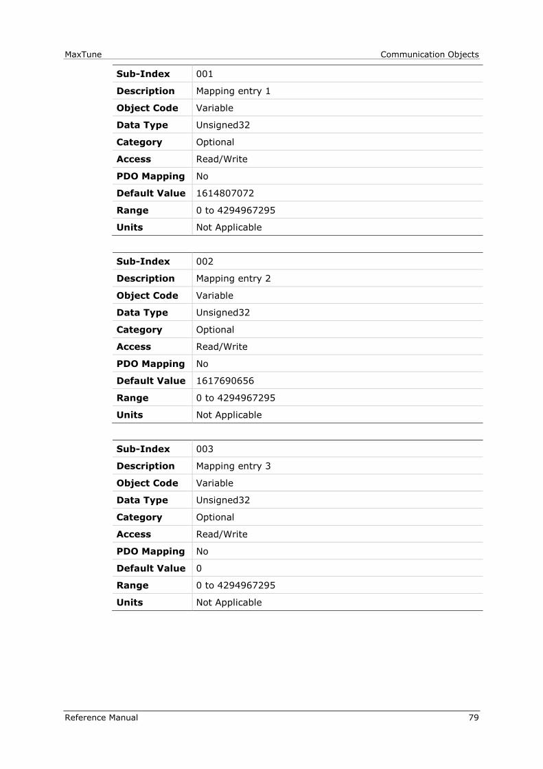
MaxTune Communication Objects
Reference Manual 79
Sub-Index 001
Description Mapping entry 1
Object Code Variable
Data Type Unsigned32
Category Optional
Access Read/Write
PDO Mapping No
Default Value 1614807072
Range 0 to 4294967295
Units Not Applicable
Sub-Index 002
Description Mapping entry 2
Object Code Variable
Data Type Unsigned32
Category Optional
Access Read/Write
PDO Mapping No
Default Value 1617690656
Range 0 to 4294967295
Units Not Applicable
Sub-Index 003
Description Mapping entry 3
Object Code Variable
Data Type Unsigned32
Category Optional
Access Read/Write
PDO Mapping No
Default Value 0
Range 0 to 4294967295
Units Not Applicable
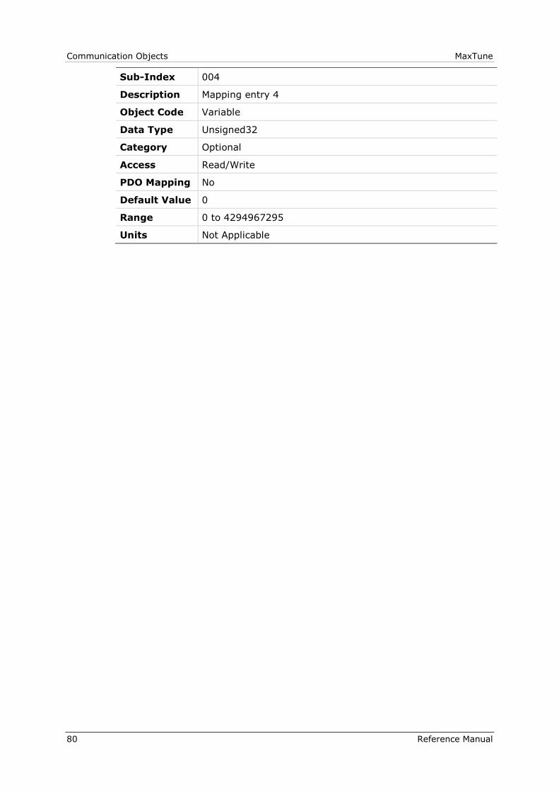
Communication Objects MaxTune
80 Reference Manual
Sub-Index 004
Description Mapping entry 4
Object Code Variable
Data Type Unsigned32
Category Optional
Access Read/Write
PDO Mapping No
Default Value 0
Range 0 to 4294967295
Units Not Applicable
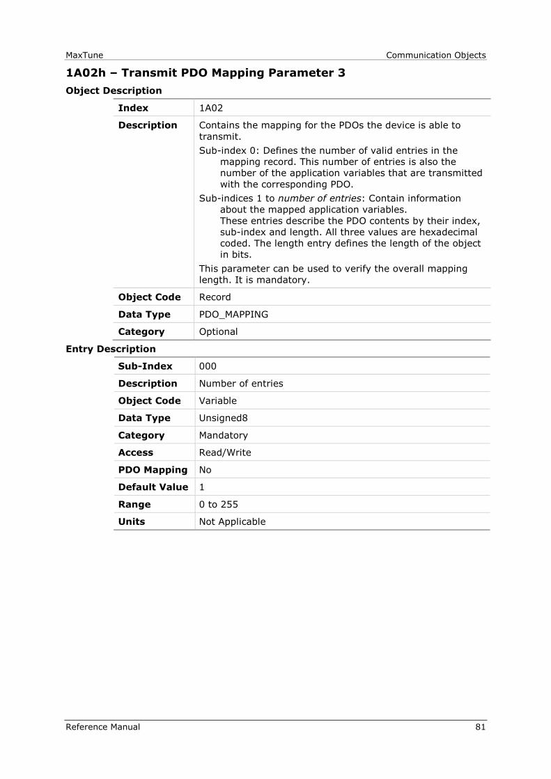
MaxTune Communication Objects
Reference Manual 81
1A02h – Transmit PDO Mapping Parameter 3
Object Description
Index 1A02
Description Contains the mapping for the PDOs the device is able to
transmit.
Sub-index 0: Defines the number of valid entries in the
mapping record. This number of entries is also the
number of the application variables that are transmitted
with the corresponding PDO.
Sub-indices 1 to number of entries: Contain information
about the mapped application variables.
These entries describe the PDO contents by their index,
sub-index and length. All three values are hexadecimal
coded. The length entry defines the length of the object
in bits.
This parameter can be used to verify the overall mapping
length. It is mandatory.
Object Code Record
Data Type PDO_MAPPING
Category Optional
Entry Description
Sub-Index 000
Description Number of entries
Object Code Variable
Data Type Unsigned8
Category Mandatory
Access Read/Write
PDO Mapping No
Default Value 1
Range 0 to 255
Units Not Applicable
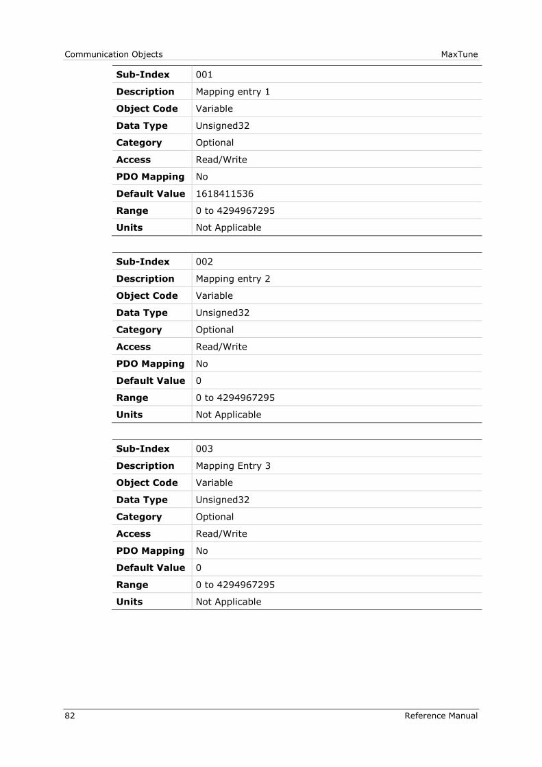
Communication Objects MaxTune
82 Reference Manual
Sub-Index 001
Description Mapping entry 1
Object Code Variable
Data Type Unsigned32
Category Optional
Access Read/Write
PDO Mapping No
Default Value 1618411536
Range 0 to 4294967295
Units Not Applicable
Sub-Index 002
Description Mapping entry 2
Object Code Variable
Data Type Unsigned32
Category Optional
Access Read/Write
PDO Mapping No
Default Value 0
Range 0 to 4294967295
Units Not Applicable
Sub-Index 003
Description Mapping Entry 3
Object Code Variable
Data Type Unsigned32
Category Optional
Access Read/Write
PDO Mapping No
Default Value 0
Range 0 to 4294967295
Units Not Applicable
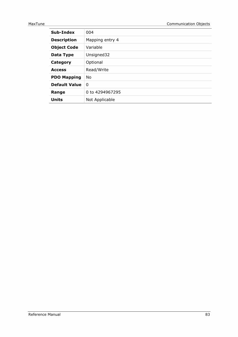
MaxTune Communication Objects
Reference Manual 83
Sub-Index 004
Description Mapping entry 4
Object Code Variable
Data Type Unsigned32
Category Optional
Access Read/Write
PDO Mapping No
Default Value 0
Range 0 to 4294967295
Units Not Applicable

Communication Objects MaxTune
84 Reference Manual
1A03h – Transmit PDO Mapping Parameter 4
Object Description
Index 1A03
Description Contains the mapping for the PDOs the device is able to
transmit.
Sub-index 0: Defines the number of valid entries in the
mapping record. This number of entries is also the
number of the application variables that are transmitted
with the corresponding PDO.
Sub-indices 1 to number of entries: Contain information
about the mapped application variables.
These entries describe the PDO contents by their index,
sub-index and length. All three values are hexadecimal
coded. The length entry defines the length of the object
in bits.
This parameter can be used to verify the overall mapping
length. It is mandatory.
Object Code Record
Data Type PDO_MAPPING
Category Optional
Entry Description
Sub-Index 000
Description Number of entries
Object Code Variable
Data Type Unsigned8
Category Mandatory
Access Read/Write
PDO Mapping No
Default Value 1
Range 0 to 255
Units Not Applicable

MaxTune Communication Objects
Reference Manual 85
Sub-Index 001
Description Mapping entry 1
Object Code Variable
Data Type Unsigned32
Category Optional
Access Read/Write
PDO Mapping No
Default Value 1627193376
Range 0 to 4294967295
Units Not Applicable
Sub-Index 002
Description Mapping entry 2
Object Code Variable
Data Type Unsigned32
Category Optional
Access Read/Write
PDO Mapping No
Default Value 0
Range 0 to 4294967295
Units Not Applicable
Sub-Index 003
Description Mapping entry 3
Object Code Variable
Data Type Unsigned32
Category Optional
Access Read/Write
PDO Mapping No
Default Value 0
Range 0 to 4294967295
Units Not Applicable

Communication Objects MaxTune
86 Reference Manual
Sub-Index 004
Description Mapping entry 4
Object Code Variable
Data Type Unsigned32
Category Optional
Access Read/Write
PDO Mapping No
Default Value 0
Range 0 to 4294967295
Units Not Applicable
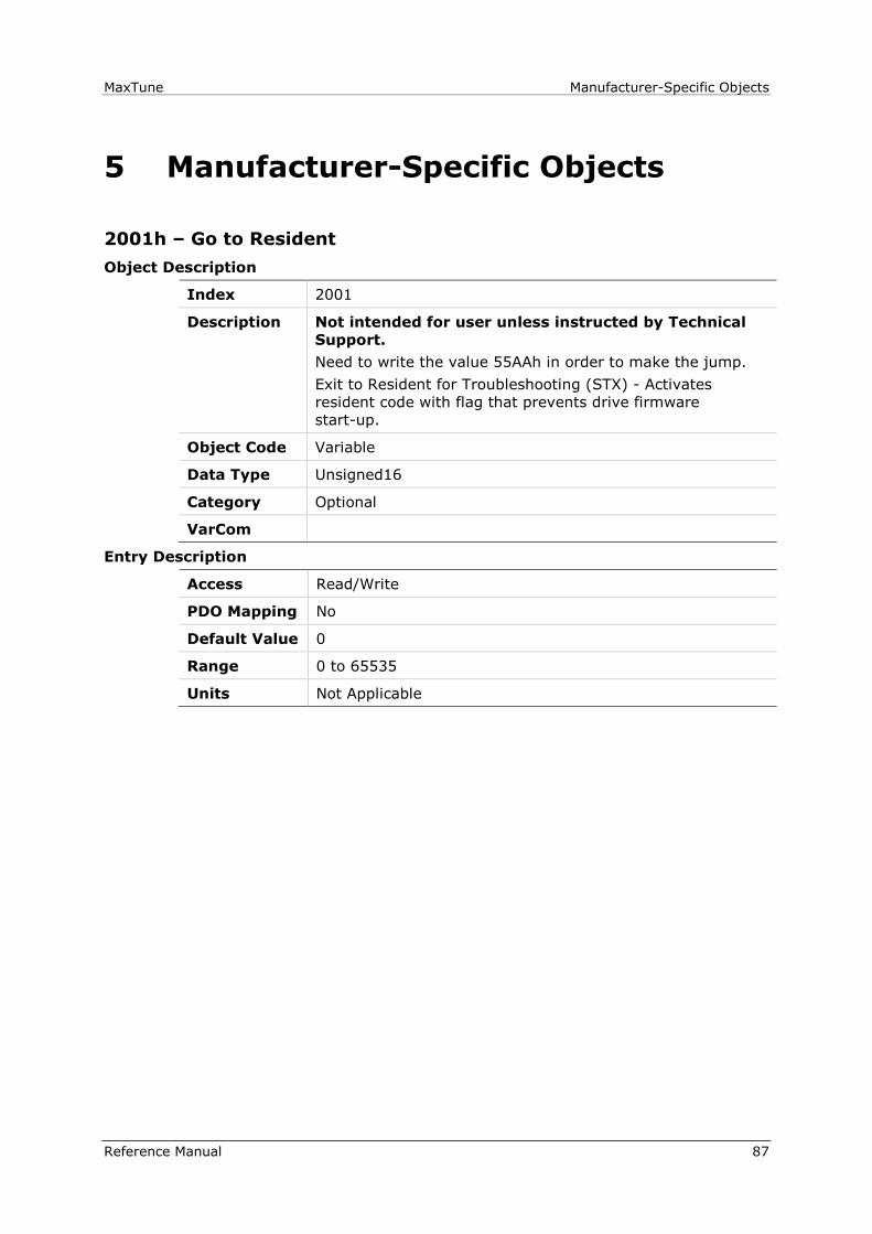
MaxTune Manufacturer-Specific Objects
Reference Manual 87
5 Manufacturer-Specific Objects
2001h – Go to Resident
Object Description
Index 2001
Description Not intended for user unless instructed by Technical
Support.
Need to write the value 55AAh in order to make the jump.
Exit to Resident for Troubleshooting (STX) - Activates
resident code with flag that prevents drive firmware
start-up.
Object Code Variable
Data Type Unsigned16
Category Optional
VarCom
Entry Description
Access Read/Write
PDO Mapping No
Default Value 0
Range 0 to 65535
Units Not Applicable

Manufacturer-Specific Objects MaxTune
88 Reference Manual
2002h – Configuration Command
Object Description
Index 2002
Description Performs a configuration sequence of the drive according to
its internal parameters.
Writing 01 initiates the configuration command.
Object Code Variable
Data Type Unsigned8
Category Optional
VarCom CONFIG
Entry Description
Access Read/Write
PDO Mapping No
Default Value 0
Range 0 to 255
Units Not Applicable
2003h – CL BEMF Gain
Object Description
Index 2003
Description The feedforward BEMF compensation ratio for the current
control.
Object Code Variable
Data Type Real32
Category Optional
VarCom KCBEMF
Entry Description
Access Read/Write
PDO Mapping No
Default Value 0.0 to 2.0
Range 1.0
Units Not Applicable
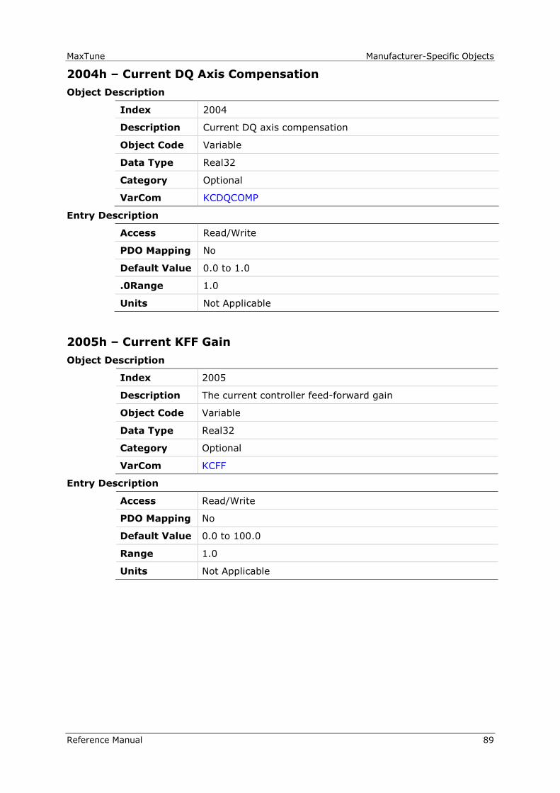
MaxTune Manufacturer-Specific Objects
Reference Manual 89
2004h – Current DQ Axis Compensation
Object Description
Index 2004
Description Current DQ axis compensation
Object Code Variable
Data Type Real32
Category Optional
VarCom KCDQCOMP
Entry Description
Access Read/Write
PDO Mapping No
Default Value 0.0 to 1.0
.0Range 1.0
Units Not Applicable
2005h – Current KFF Gain
Object Description
Index 2005
Description The current controller feed-forward gain
Object Code Variable
Data Type Real32
Category Optional
VarCom KCFF
Entry Description
Access Read/Write
PDO Mapping No
Default Value 0.0 to 100.0
Range 1.0
Units Not Applicable

Manufacturer-Specific Objects MaxTune
90 Reference Manual
2006h – Current KI Gain
Object Description
Index 2006
Description The current controller integrator gain
Object Code Variable
Data Type Real32
Category Optional
VarCom KCI
Entry Description
Access Read/Write
PDO Mapping No
Default Value 0.0 to 100.0
Range 1.0
Units Not Applicable
2007h – Current KP Gain
Object Description
Index 2007
Description The current controller proportional gain.
Object Code Variable
Data Type Real32
Category Optional
VarCom KCP
Entry Description
Access Read/Write
PDO Mapping No
Default Value 0.0 to 100.0
Range 1.0
Units Not Applicable
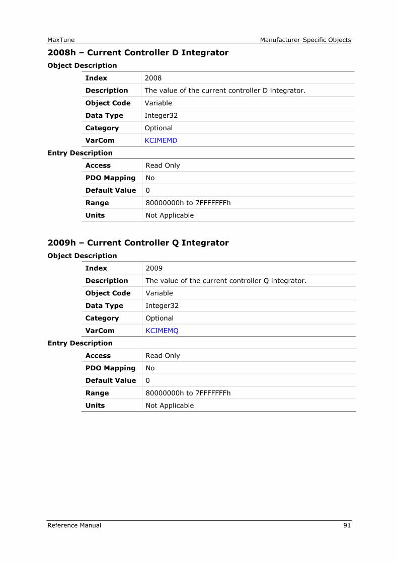
MaxTune Manufacturer-Specific Objects
Reference Manual 91
2008h – Current Controller D Integrator
Object Description
Index 2008
Description The value of the current controller D integrator.
Object Code Variable
Data Type Integer32
Category Optional
VarCom KCIMEMD
Entry Description
Access Read Only
PDO Mapping No
Default Value 0
Range 80000000h to 7FFFFFFFh
Units Not Applicable
2009h – Current Controller Q Integrator
Object Description
Index 2009
Description The value of the current controller Q integrator.
Object Code Variable
Data Type Integer32
Category Optional
VarCom KCIMEMQ
Entry Description
Access Read Only
PDO Mapping No
Default Value 0
Range 80000000h to 7FFFFFFFh
Units Not Applicable

Manufacturer-Specific Objects MaxTune
92 Reference Manual
200Ah – HD Anti-Vibration Filter
Object Description
Index 200A
Description Not intended for user unless instructed by Technical
Support.
HD anti-vibration filter
Object Code Variable
Data Type Real32
Category Optional
VarCom NLANTIVIBHZ
Entry Description
Access Read/Write
PDO Mapping No
Default Value 1.0 to 100.0
Range 100.0
Units hertz (Hz)
200Bh – HD Anti-Resonance Sharpness
Object Description
Index 200B
Description Not intended for user unless instructed by Technical
Support.
HD anti-resonance sharpness
Object Code Variable
Data Type Real32
Category Optional
VarCom NLANTIVIBSHARP
Entry Description
Access Read/Write
PDO Mapping No
Default Value 1.0
Range 0.1 to 10.0
Units Not Applicable

MaxTune Manufacturer-Specific Objects
Reference Manual 93
200Ch – HD Anti-Vibration Gain
Object Description
Index 200C
Description HD anti-vibration gain
Object Code Variable
Data Type Real32
Category Optional
VarCom NLANTIVIBGAIN
Entry Description
Access Read/Write
PDO Mapping No
Default Value 0.0
Range 0.0 to 10000.0
Units Rad×10-3/N
200Dh – Absolute Feedback Offset
Object Description
Index 200D
Description The initial absolute position after power-cycle.
Object Code Variable
Data Type Integer32
Category Optional
VarCom ABSOFFSET
Entry Description
Access Read/Write
PDO Mapping No
Default Value 0
Range -2147483648 to 2147483647
Units CAN position user units

Manufacturer-Specific Objects MaxTune
94 Reference Manual
200Eh – Auto Home Mode
Object Description
Index 200E
Description The type of automatic homing to be performed on power up.
0 = No Homing
1 = Attempt once at Power-Up. Fail once.
2 = Attempt at Power-Up. Perform whenever possible.
Object Code Variable
Data Type Unsigned16
Category Optional
VarCom AUTOHOME
Entry Description
Access Read/Write
PDO Mapping No
Default Value 0
Range 0 to 2
Units Not Applicable
200Fh – Field Bus Unit Scaling
Object Description
Index 200F
Description Field bus unit scaling for internal counts stating how many
bits of 32-bit position are for number of revolutions.
Object Code Variable
Data Type Unsigned16
Category Optional
VarCom FBSCALE
Entry Description
Access Read/Write
PDO Mapping No
Default Value 12
Range 0 to 20
Units Not Applicable

MaxTune Manufacturer-Specific Objects
Reference Manual 95
2010h – Velocity Loop Bandwidth
Object Description
Index 2010
Description The velocity control loop bandwidth for the pole placement
controller.
Object Code Variable
Data Type Unsigned16
Category Optional
VarCom BW
Entry Description
Access Read/Write
PDO Mapping No
Default Value 30
Range 10 to 600
Units Hz
2013h – Current CL VD
Object Description
Index 2013
Description The voltage command to the D component.
Object Code Variable
Data Type Integer16
Category Optional
VarCom CLVD
Entry Description
Access Read Only
PDO Mapping No
Default Value 0
Range -32768 to 32767
Units Not Applicable
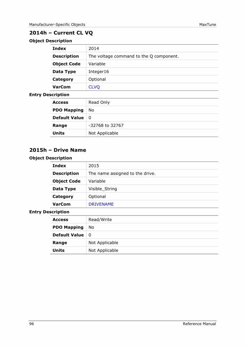
Manufacturer-Specific Objects MaxTune
96 Reference Manual
2014h – Current CL VQ
Object Description
Index 2014
Description The voltage command to the Q component.
Object Code Variable
Data Type Integer16
Category Optional
VarCom CLVQ
Entry Description
Access Read Only
PDO Mapping No
Default Value 0
Range -32768 to 32767
Units Not Applicable
2015h – Drive Name
Object Description
Index 2015
Description The name assigned to the drive.
Object Code Variable
Data Type Visible_String
Category Optional
VarCom DRIVENAME
Entry Description
Access Read/Write
PDO Mapping No
Default Value 0
Range Not Applicable
Units Not Applicable

MaxTune Manufacturer-Specific Objects
Reference Manual 97
2016h – Electrical Position
Object Description
Index 2016
Description The electrical angle position in 16-bit resolution.
Object Code Variable
Data Type Unsigned16
Category Optional
VarCom ELECTANGLE
Entry Description
Access Read Only
PDO Mapping No
Default Value 0
Range 0 to 65535
Units 65536/electrical cycle
2017h – HD Derivative Gain
Object Description
Index 2017
Description HD derivative gain
Object Code Variable
Data Type Real32
Category Optional
VarCom KNLD
Entry Description
Access Read/Write
PDO Mapping 0.0
Default Value 0.0
Range 0.0 to 2000.0
Units hertz (Hz)
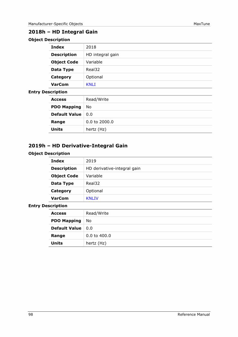
Manufacturer-Specific Objects MaxTune
98 Reference Manual
2018h – HD Integral Gain
Object Description
Index 2018
Description HD integral gain
Object Code Variable
Data Type Real32
Category Optional
VarCom KNLI
Entry Description
Access Read/Write
PDO Mapping No
Default Value 0.0
Range 0.0 to 2000.0
Units hertz (Hz)
2019h – HD Derivative-Integral Gain
Object Description
Index 2019
Description HD derivative-integral gain
Object Code Variable
Data Type Real32
Category Optional
VarCom KNLIV
Entry Description
Access Read/Write
PDO Mapping No
Default Value 0.0
Range 0.0 to 400.0
Units hertz (Hz)

MaxTune Manufacturer-Specific Objects
Reference Manual 99
201Ah – HD Proportional Gain
Object Description
Index 201A
Description HD proportional gain
Object Code Variable
Data Type Real32
Category Optional
VarCom KNLP
Entry Description
Access Read/Write
PDO Mapping No
Default Value 0.0
Range 0.0 to 400.0
Units hertz (Hz)
201Bh – HD Adaptive Gain Scale Factor
Object Description
Index 201B
Description HD adaptive gain scale factor
Object Code Variable
Data Type Real32
Category Optional
VarCom KNLUSERGAIN
Entry Description
Access Read/Write
PDO Mapping No
Default Value 1.0
Range 0.001 to 3.0
Units Not Applicable
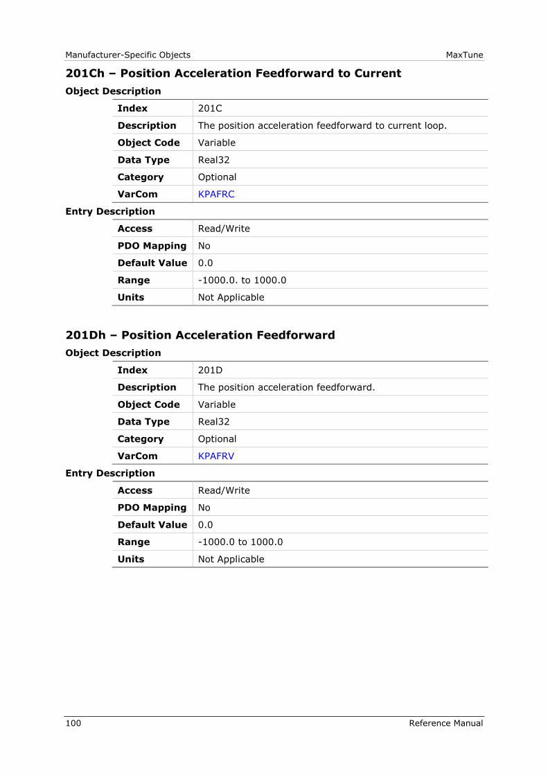
Manufacturer-Specific Objects MaxTune
100 Reference Manual
201Ch – Position Acceleration Feedforward to Current
Object Description
Index 201C
Description The position acceleration feedforward to current loop.
Object Code Variable
Data Type Real32
Category Optional
VarCom KPAFRC
Entry Description
Access Read/Write
PDO Mapping No
Default Value 0.0
Range -1000.0. to 1000.0
Units Not Applicable
201Dh – Position Acceleration Feedforward
Object Description
Index 201D
Description The position acceleration feedforward.
Object Code Variable
Data Type Real32
Category Optional
VarCom KPAFRV
Entry Description
Access Read/Write
PDO Mapping No
Default Value 0.0
Range -1000.0 to 1000.0
Units Not Applicable

MaxTune Manufacturer-Specific Objects
Reference Manual 101
201Eh – Position Derivative Gain
Object Description
Index 201E
Description The position derivative gain.
Object Code Variable
Data Type Real32
Category Optional
VarCom KPD
Entry Description
Access Read/Write
PDO Mapping No
Default Value 0.0
Range 0.0 to 1000.0
Units Not Applicable
201Fh – Position Proportional Adaptive Gain
Object Description
Index 201F
Description The position adaptive proportional gain.
Object Code Variable
Data Type Real32
Category Optional
VarCom KPE
Entry Description
Access Read/Write
PDO Mapping No
Default Value 0.0
Range 0.0 to 4.0
Units Not Applicable
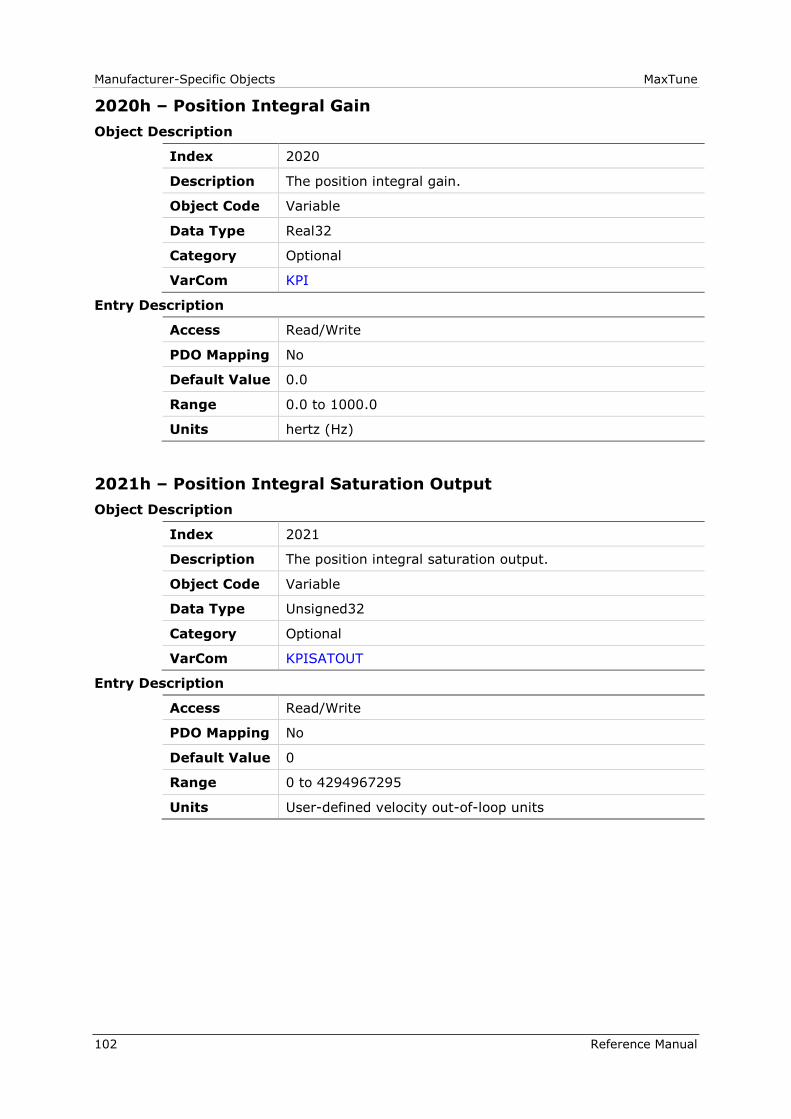
Manufacturer-Specific Objects MaxTune
102 Reference Manual
2020h – Position Integral Gain
Object Description
Index 2020
Description The position integral gain.
Object Code Variable
Data Type Real32
Category Optional
VarCom KPI
Entry Description
Access Read/Write
PDO Mapping No
Default Value 0.0
Range 0.0 to 1000.0
Units hertz (Hz)
2021h – Position Integral Saturation Output
Object Description
Index 2021
Description The position integral saturation output.
Object Code Variable
Data Type Unsigned32
Category Optional
VarCom KPISATOUT
Entry Description
Access Read/Write
PDO Mapping No
Default Value 0
Range 0 to 4294967295
Units User-defined velocity out-of-loop units

MaxTune Manufacturer-Specific Objects
Reference Manual 103
2022h – Position Proportional Gain
Object Description
Index 2022
Description The position proportional gain.
Object Code Variable
Data Type Real32
Category Optional
VarCom KPP
Entry Description
Access Read/Write
PDO Mapping No
Default Value 1.0
Range 0.0 to 1200.0
Units Not Applicable
2023h – Position Velocity Feedforward
Object Description
Index 2023
Description The position control velocity feedforward.
Object Code Variable
Data Type Real32
Category Optional
VarCom KPVFR
Entry Description
Access Read/Write
PDO Mapping No
Default Value 0.0
Range -1000.0 to 1000.0
Units Not Applicable

Manufacturer-Specific Objects MaxTune
104 Reference Manual
2025h – Velocity Feedforward Ratio
Object Description
Index 2025
Description The velocity feedforward ratio.
Object Code Variable
Data Type Real32
Category Optional
VarCom KVFR
Entry Description
Access Read/Write
PDO Mapping No
Default Value 0.0
Range 0.0 to 1.0
Units Not Applicable
2026h – Velocity Integrator
Object Description
Index 2026
Description The velocity integral gain.
Object Code Variable
Data Type Real32
Category Optional
VarCom KVI
Entry Description
Access Read/Write
PDO Mapping No
Default Value 0.0
Range 0.0 to 200000.0
Units hertz (Hz)
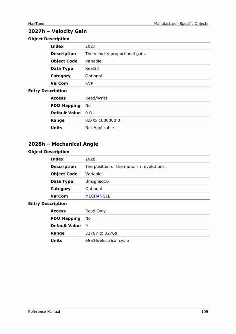
MaxTune Manufacturer-Specific Objects
Reference Manual 105
2027h – Velocity Gain
Object Description
Index 2027
Description The velocity proportional gain.
Object Code Variable
Data Type Real32
Category Optional
VarCom KVP
Entry Description
Access Read/Write
PDO Mapping No
Default Value 0.01
Range 0.0 to 1000000.0
Units Not Applicable
2028h – Mechanical Angle
Object Description
Index 2028
Description The position of the motor in revolutions.
Object Code Variable
Data Type Unsigned16
Category Optional
VarCom MECHANGLE
Entry Description
Access Read Only
PDO Mapping No
Default Value 0
Range 32767 to 32768
Units 65536/electrical cycle
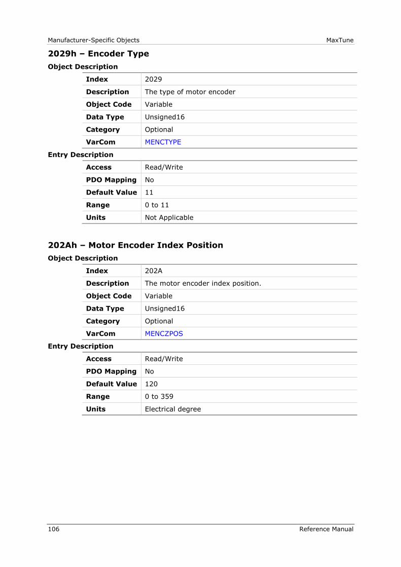
Manufacturer-Specific Objects MaxTune
106 Reference Manual
2029h – Encoder Type
Object Description
Index 2029
Description The type of motor encoder
Object Code Variable
Data Type Unsigned16
Category Optional
VarCom MENCTYPE
Entry Description
Access Read/Write
PDO Mapping No
Default Value 11
Range 0 to 11
Units Not Applicable
202Ah – Motor Encoder Index Position
Object Description
Index 202A
Description The motor encoder index position.
Object Code Variable
Data Type Unsigned16
Category Optional
VarCom MENCZPOS
Entry Description
Access Read/Write
PDO Mapping No
Default Value 120
Range 0 to 359
Units Electrical degree
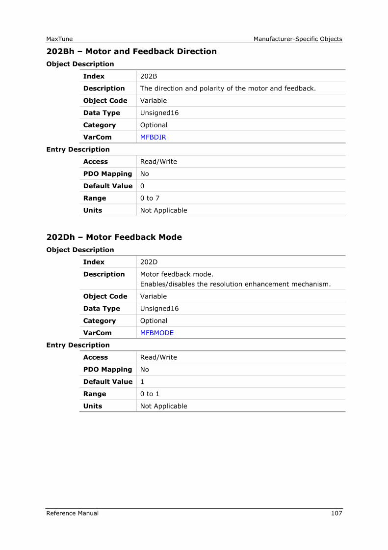
MaxTune Manufacturer-Specific Objects
Reference Manual 107
202Bh – Motor and Feedback Direction
Object Description
Index 202B
Description The direction and polarity of the motor and feedback.
Object Code Variable
Data Type Unsigned16
Category Optional
VarCom MFBDIR
Entry Description
Access Read/Write
PDO Mapping No
Default Value 0
Range 0 to 7
Units Not Applicable
202Dh – Motor Feedback Mode
Object Description
Index 202D
Description Motor feedback mode.
Enables/disables the resolution enhancement mechanism.
Object Code Variable
Data Type Unsigned16
Category Optional
VarCom MFBMODE
Entry Description
Access Read/Write
PDO Mapping No
Default Value 1
Range 0 to 1
Units Not Applicable
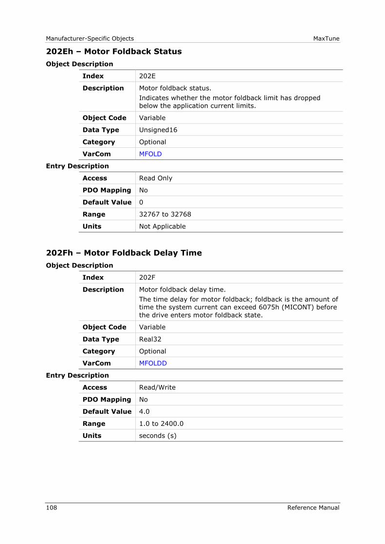
Manufacturer-Specific Objects MaxTune
108 Reference Manual
202Eh – Motor Foldback Status
Object Description
Index 202E
Description Motor foldback status.
Indicates whether the motor foldback limit has dropped
below the application current limits.
Object Code Variable
Data Type Unsigned16
Category Optional
VarCom MFOLD
Entry Description
Access Read Only
PDO Mapping No
Default Value 0
Range 32767 to 32768
Units Not Applicable
202Fh – Motor Foldback Delay Time
Object Description
Index 202F
Description Motor foldback delay time.
The time delay for motor foldback; foldback is the amount of
time the system current can exceed 6075h (MICONT) before
the drive enters motor foldback state.
Object Code Variable
Data Type Real32
Category Optional
VarCom MFOLDD
Entry Description
Access Read/Write
PDO Mapping No
Default Value 4.0
Range 1.0 to 2400.0
Units seconds (s)

MaxTune Manufacturer-Specific Objects
Reference Manual 109
2030h – Motor Foldback Disable
Object Description
Index 2030
Description Motor foldback disable.
Enables/disables motor foldback protection.
Object Code Variable
Data Type Unsigned16
Category Optional
VarCom MFOLDDIS
Entry Description
Access Read/Write
PDO Mapping No
Default Value 0
Range 0 to 1
Units Not Applicable
2031h – Motor Foldback Recovery Time
Object Description
Index 2031
Description The recovery time for motor foldback.
Object Code Variable
Data Type Real32
Category Optional
VarCom MFOLDR
Entry Description
Access Read/Write
PDO Mapping No
Default Value 70.0
Range 5.0 to 3600.0
Units seconds (s)
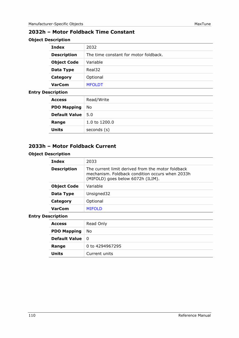
Manufacturer-Specific Objects MaxTune
110 Reference Manual
2032h – Motor Foldback Time Constant
Object Description
Index 2032
Description The time constant for motor foldback.
Object Code Variable
Data Type Real32
Category Optional
VarCom MFOLDT
Entry Description
Access Read/Write
PDO Mapping No
Default Value 5.0
Range 1.0 to 1200.0
Units seconds (s)
2033h – Motor Foldback Current
Object Description
Index 2033
Description The current limit derived from the motor foldback
mechanism. Foldback condition occurs when 2033h
(MIFOLD) goes below 6072h (ILIM).
Object Code Variable
Data Type Unsigned32
Category Optional
VarCom MIFOLD
Entry Description
Access Read Only
PDO Mapping No
Default Value 0
Range 0 to 4294967295
Units Current units

MaxTune Manufacturer-Specific Objects
Reference Manual 111
2034h – Motor Foldback Fault Threshold
Object Description
Index 2034
Description The motor foldback fault threshold.
Object Code Variable
Data Type Unsigned32
Category Optional
VarCom MIFOLDFTHRESH
Entry Description
Access Read/Write
PDO Mapping No
Default Value 0
Range 0 to 4294967295
Units Current units
2035h – Motor Foldback Warning Threshold
Object Description
Index 2035
Description The motor foldback fault warning threshold.
Object Code Variable
Data Type Unsigned32
Category Optional
VarCom MIFOLDWTHRESH
Entry Description
Access Read/Write
PDO Mapping No
Default Value 0
Range 0 to 4294967295
Units Current units
Manufacturer-Specific Objects MaxTune
112 Reference Manual
2036h – Motor Peak Current
Object Description
Index 2036
Description The peak rated current of the motor
Object Code Variable
Data Type Real32
Category Optional
VarCom MIPEAK
Entry Description
Access Read/Write
PDO Mapping No
Default Value 0.1
Range 0.1 to 150
Units mA
2037h – Rotor Inertia
Object Description
Index 2037
Description The rotor inertia for rotary motors
Object Code Variable
Data Type Real32
Category Optional
VarCom MJ
Entry Description
Access Read/Write
PDO Mapping No
Default Value 0
Range 0.02 to 200000
Units kg×m2×10-3
MaxTune Manufacturer-Specific Objects
Reference Manual 113
2038h – Torque Constant for Linear Motors
Object Description
Index 2038
Description The motor torque constant for linear motors.
Object Code Variable
Data Type Real32
Category Optional
VarCom MKF
Entry Description
Access Read/Write
PDO Mapping No
Default Value 0.01600000076
Range 0.0010000000475 to 1000.0
Units Not Applicable
2039h – Torque Constant
Object Description
Index 2039
Description The motor torque constant.
Object Code Variable
Data Type Real32
Category Optional
VarCom MKT
Entry Description
Access Read/Write
PDO Mapping No
Default Value 0.016
Range 0.001 to 65.0
Units Not Applicable

Manufacturer-Specific Objects MaxTune
114 Reference Manual
203Ah – Motor Inductance
Object Description
Index 203A
Description The motor minimum line-to-line inductance.
Object Code Variable
Data Type Real32
Category Optional
VarCom ML
Entry Description
Access Read/Write
PDO Mapping No
Default Value 0.001
Range 0.0 to 1000.0
Units megahertz (MHz)
203Bh – Adaptive Gain Value at Continuous Motor Current
Object Description
Index 203B
Description The current loop adaptive gain value at continuous motor
current.
Object Code Variable
Data Type Real32
Category Optional
VarCom MLGAINC
Entry Description
Access Read/Write
PDO Mapping No
Default Value 1.0
Range 0.1 to 1.0
Units Not Applicable

MaxTune Manufacturer-Specific Objects
Reference Manual 115
203Ch – Adaptive Gain Value at Peak Motor Current
Object Description
Index 203C
Description The current loop adaptive gain value at peak motor current.
Object Code Variable
Data Type Real32
Category Optional
VarCom MLGAINP
Entry Description
Access Read/Write
PDO Mapping No
Default Value 1.0
Range 0.1 to 1.0
Units Not Applicable
203Dh – Rotor Coil Mass (Linear Motor)
Object Description
Index 203D
Description The moveable mass of linear motor without payload.
Object Code Variable
Data Type Real32
Category Optional
VarCom MMASS
Entry Description
Access Read/Write
PDO Mapping No
Default Value 0.0
Range 0.0 to 10000.0
Units kilogram (kg)
Manufacturer-Specific Objects MaxTune
116 Reference Manual
203Eh – Motor Commutation Type
Object Description
Index 203E
Description The type of motor commutation - brushless or brush.
Object Code Variable
Data Type Unsigned16
Category Optional
VarCom MOTORCOMMTYPE
Entry Description
Access Read/Write
PDO Mapping No
Default Value 0
Range 0 to 1
Units Not Applicable
203Fh – Motor Name
Object Description
Index 203F
Description The name assigned to the motor
Object Code Variable
Data Type Visible_String
Category Optional
VarCom MOTORNAME
Entry Description
Access Read/Write
PDO Mapping No
Default Value 0
Range Not Applicable
Units Not Applicable
MaxTune Manufacturer-Specific Objects
Reference Manual 117
2040h – Phase Disconnect Scan
Object Description
Index 2040
Description Enables/disables detection of wire breaks in motor phases.
Object Code Variable
Data Type Unsigned16
Category Optional
VarCom MOTORPHASESCAN
Entry Description
Access Read/Write
PDO Mapping No
Default Value 0
Range 0 to 1
Units Not Applicable
2043h – Commutation Offset
Object Description
Index 2043
Description The resolver/encoder phase relative to the standard
commutation table.
Object Code Variable
Data Type Unsigned16
Category Optional
VarCom MPHASE
Entry Description
Access Read/Write
PDO Mapping No
Default Value 0
Range 0 to 359
Units degrees (°)

Manufacturer-Specific Objects MaxTune
118 Reference Manual
2044h – Drive Temperature
Object Description
Index 2044
Description The temperature of the drive control and power boards
(Celsius degrees).
Sub-index 1 = Control board temperature
Sub-index 2 = Power board temperature
Object Code Array
Data Type Integer16
Category Optional
VarCom DRIVETEMP
Entry Description
Sub-Index 000
Description Number of entries
Category Optional
Data Type Unsigned8
Access Read Only
PDO Mapping No
Default Value 2
Range 0 to 2
Units Not Applicable
Sub-Index 001
Description Control Temperature
Category Optional
Data Type Integer16
Access Read Only
PDO Mapping No
Default Value 0
Range -32768 to 32767
Units Celsius degrees (°C)

MaxTune Manufacturer-Specific Objects
Reference Manual 119
Sub-Index 002
Description Power Temperature
Category Optional
Data Type Integer16
Access Read Only
PDO Mapping No
Default Value 0
Range -32768 to 32767
Units Celsius degrees (°C)
2045h – Feedback Direction
Object Description
Index 2045
Description Feedback positive direction.
Object Code Variable
Data Type Unsigned16
Category Optional
VarCom DIR
Entry Description
Access Read/Write
PDO Mapping No
Default Value 0
Range 0 to 1
Units Not Applicable
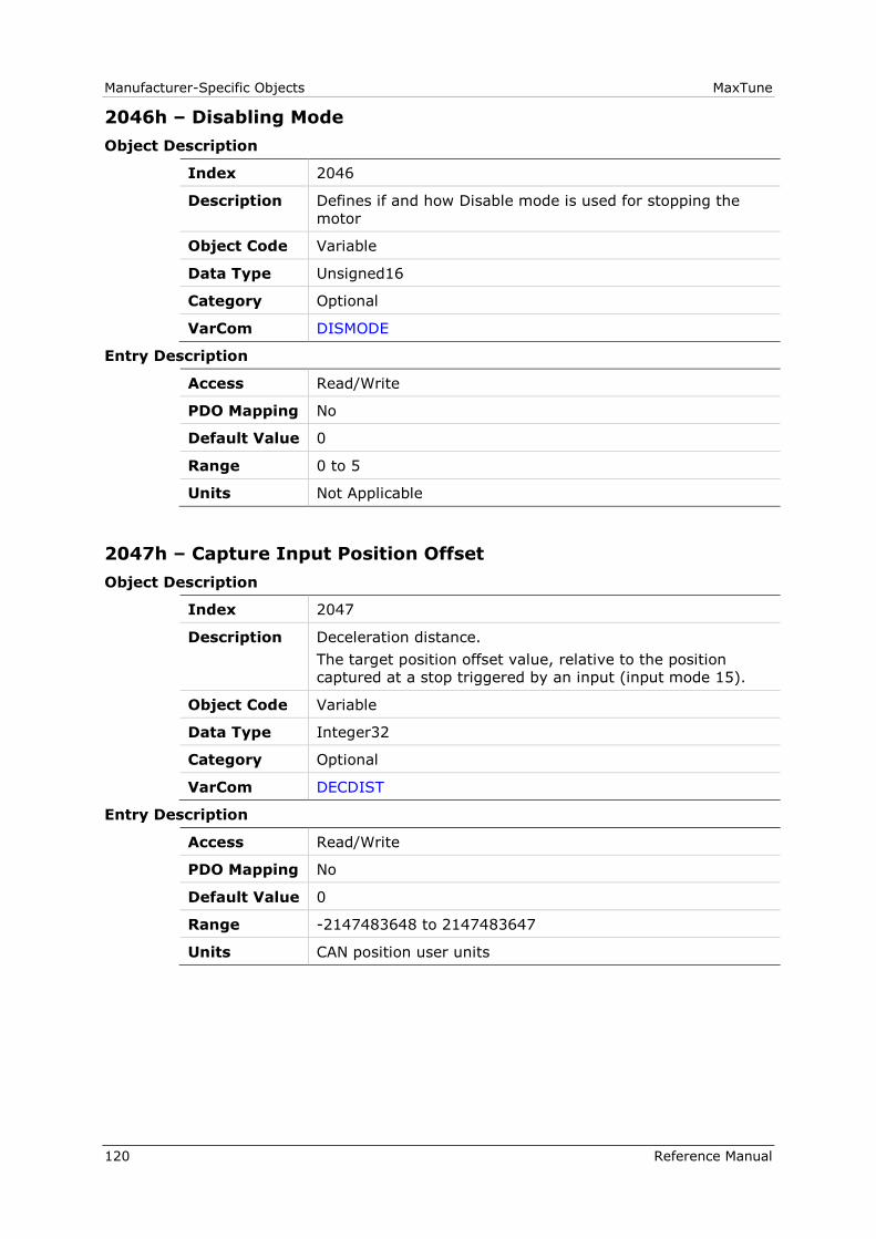
Manufacturer-Specific Objects MaxTune
120 Reference Manual
2046h – Disabling Mode
Object Description
Index 2046
Description Defines if and how Disable mode is used for stopping the
motor
Object Code Variable
Data Type Unsigned16
Category Optional
VarCom DISMODE
Entry Description
Access Read/Write
PDO Mapping No
Default Value 0
Range 0 to 5
Units Not Applicable
2047h – Capture Input Position Offset
Object Description
Index 2047
Description Deceleration distance.
The target position offset value, relative to the position
captured at a stop triggered by an input (input mode 15).
Object Code Variable
Data Type Integer32
Category Optional
VarCom DECDIST
Entry Description
Access Read/Write
PDO Mapping No
Default Value 0
Range -2147483648 to 2147483647
Units CAN position user units

MaxTune Manufacturer-Specific Objects
Reference Manual 121
2048h – Capture Input Position Offset 2
Object Description
Index 2048
Description Deceleration distance 2.
The target position offset value, relative to the position
captured at a stop triggered by an input (input mode 16).
Object Code Variable
Data Type Integer32
Category Optional
VarCom DECDIST2
Entry Description
Access Read/Write
PDO Mapping No
Default Value 0
Range -2147483648 to 2147483647
Units CAN position user units
2049h – Quick Stop Deceleration Time
Object Description
Index 2049
Description The deceleration time for an Active Disable/emergency stop.
Object Code Variable
Data Type Unsigned16
Category Optional
VarCom DECSTOPTIME
Entry Description
Access Read/Write
PDO Mapping No
Default Value 0
Range 0 to 6500
Units milliseconds (ms)
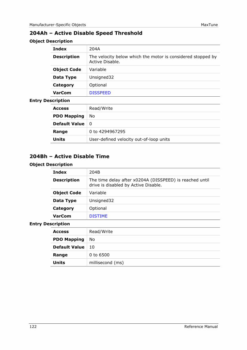
Manufacturer-Specific Objects MaxTune
122 Reference Manual
204Ah – Active Disable Speed Threshold
Object Description
Index 204A
Description The velocity below which the motor is considered stopped by
Active Disable.
Object Code Variable
Data Type Unsigned32
Category Optional
VarCom DISSPEED
Entry Description
Access Read/Write
PDO Mapping No
Default Value 0
Range 0 to 4294967295
Units User-defined velocity out-of-loop units
204Bh – Active Disable Time
Object Description
Index 204B
Description The time delay after x0204A (DISSPEED) is reached until
drive is disabled by Active Disable.
Object Code Variable
Data Type Unsigned32
Category Optional
VarCom DISTIME
Entry Description
Access Read/Write
PDO Mapping No
Default Value 10
Range 0 to 6500
Units millisecond (ms)
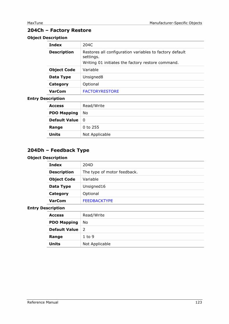
MaxTune Manufacturer-Specific Objects
Reference Manual 123
204Ch – Factory Restore
Object Description
Index 204C
Description Restores all configuration variables to factory default
settings.
Writing 01 initiates the factory restore command.
Object Code Variable
Data Type Unsigned8
Category Optional
VarCom FACTORYRESTORE
Entry Description
Access Read/Write
PDO Mapping No
Default Value 0
Range 0 to 255
Units Not Applicable
204Dh – Feedback Type
Object Description
Index 204D
Description The type of motor feedback.
Object Code Variable
Data Type Unsigned16
Category Optional
VarCom FEEDBACKTYPE
Entry Description
Access Read/Write
PDO Mapping No
Default Value 2
Range 1 to 9
Units Not Applicable
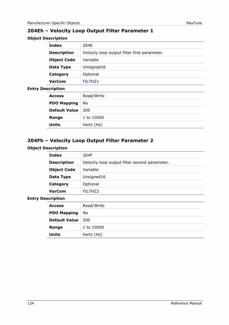
Manufacturer-Specific Objects MaxTune
124 Reference Manual
204Eh – Velocity Loop Output Filter Parameter 1
Object Description
Index 204E
Description Velocity loop output filter first parameter.
Object Code Variable
Data Type Unsigned16
Category Optional
VarCom FILTHZ1
Entry Description
Access Read/Write
PDO Mapping No
Default Value 200
Range 1 to 10000
Units hertz (Hz)
204Fh – Velocity Loop Output Filter Parameter 2
Object Description
Index 204F
Description Velocity loop output filter second parameter.
Object Code Variable
Data Type Unsigned16
Category Optional
VarCom FILTHZ2
Entry Description
Access Read/Write
PDO Mapping No
Default Value 200
Range 1 to 10000
Units hertz (Hz)
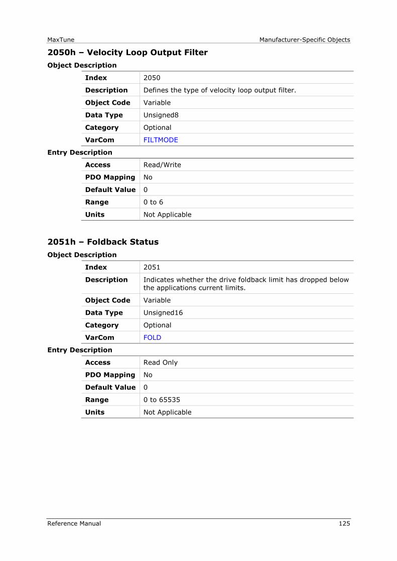
MaxTune Manufacturer-Specific Objects
Reference Manual 125
2050h – Velocity Loop Output Filter
Object Description
Index 2050
Description Defines the type of velocity loop output filter.
Object Code Variable
Data Type Unsigned8
Category Optional
VarCom FILTMODE
Entry Description
Access Read/Write
PDO Mapping No
Default Value 0
Range 0 to 6
Units Not Applicable
2051h – Foldback Status
Object Description
Index 2051
Description Indicates whether the drive foldback limit has dropped below
the applications current limits.
Object Code Variable
Data Type Unsigned16
Category Optional
VarCom FOLD
Entry Description
Access Read Only
PDO Mapping No
Default Value 0
Range 0 to 65535
Units Not Applicable

Manufacturer-Specific Objects MaxTune
126 Reference Manual
2052h – Friction Compensation Negative Current
Object Description
Index 2052
Description The current added to the current command when the
commanded velocity is negative. Limited by 207Bh
(DIPEAK).
Object Code Variable
Data Type Real32
Category Optional
VarCom FRICINEG
Entry Description
Access Read/Write
PDO Mapping No
Default Value 0.0
Range -3.40282346639e+038 to 3.40282346639e+038
Units ampere (A)
2053h – Friction Compensation Positive Current
Object Description
Index 2053
Description The current added to the current command when the
commanded velocity is positive. Limited by 207Bh (DIPEAK).
Object Code Variable
Data Type Real32
Category Optional
VarCom FRICIPOS
Entry Description
Access Read/Write
PDO Mapping No
Default Value 0.0
Range -3.40282346639e+038 to 3.40282346639e+038
Units ampere (A)
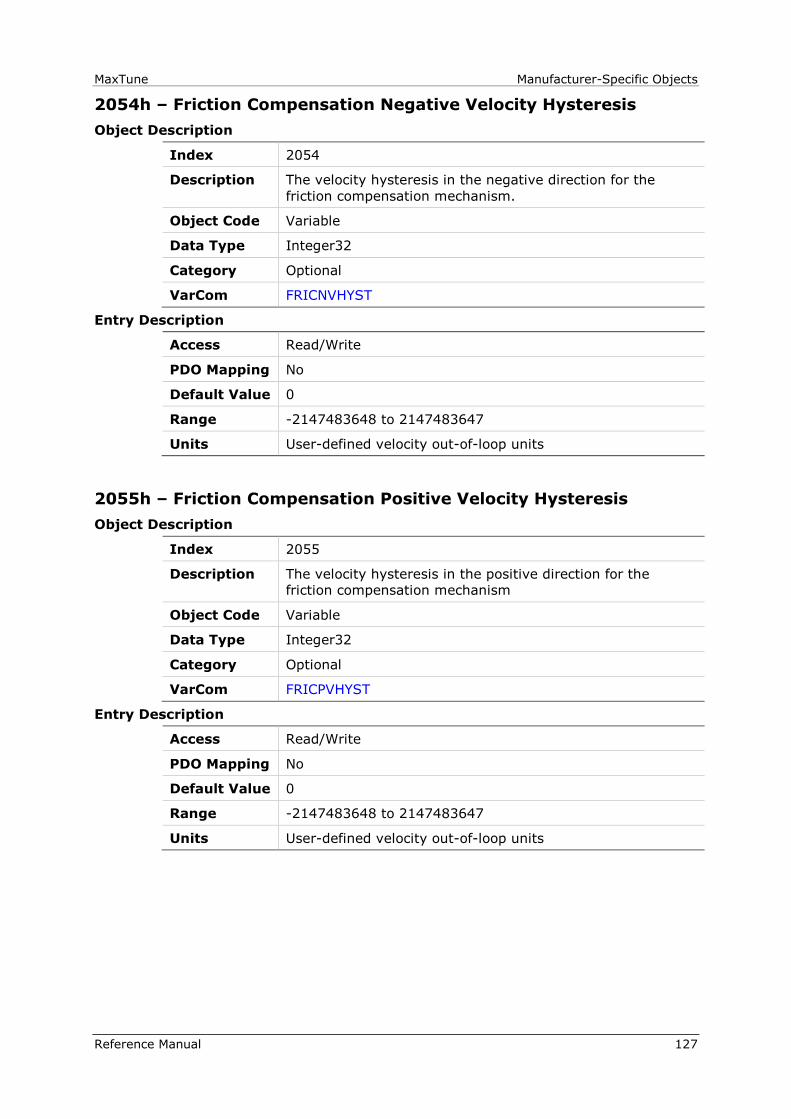
MaxTune Manufacturer-Specific Objects
Reference Manual 127
2054h – Friction Compensation Negative Velocity Hysteresis
Object Description
Index 2054
Description The velocity hysteresis in the negative direction for the
friction compensation mechanism.
Object Code Variable
Data Type Integer32
Category Optional
VarCom FRICNVHYST
Entry Description
Access Read/Write
PDO Mapping No
Default Value 0
Range -2147483648 to 2147483647
Units User-defined velocity out-of-loop units
2055h – Friction Compensation Positive Velocity Hysteresis
Object Description
Index 2055
Description The velocity hysteresis in the positive direction for the
friction compensation mechanism
Object Code Variable
Data Type Integer32
Category Optional
VarCom FRICPVHYST
Entry Description
Access Read/Write
PDO Mapping No
Default Value 0
Range -2147483648 to 2147483647
Units User-defined velocity out-of-loop units

Manufacturer-Specific Objects MaxTune
128 Reference Manual
2056h – Halls State
Object Description
Index 2056
Description The state of the Hall commutation sensors.
Sub-index 1 = Hall U
Sub-index 2 = Hall V
Sub-index 3 = Hall W
Object Code Array
Data Type Unsigned8
Category Optional
VarCom HALLS
Entry Description
Sub-Index 000
Description Number of entries
Object Code Variable
Data Type Unsigned8
Category Optional
Access Read Only
PDO Mapping No
Default Value 3
Range 0 to 3
Units Not Applicable
Sub-Index 001
Description Hall U
Object Code Variable
Data Type Unsigned8
Category Optional
Access Read Only
PDO Mapping No
Default Value 0
Range 0 to 1
Units Not Applicable

MaxTune Manufacturer-Specific Objects
Reference Manual 129
Sub-Index 002
Description Hall V
Object Code Variable
Data Type Unsigned8
Category Optional
Access Read Only
PDO Mapping No
Default Value 0
Range 0 to 1
Units Not Applicable
Sub-Index 003
Description Hall W
Object Code Variable
Data Type Unsigned8
Category Optional
Access Read Only
PDO Mapping No
Default Value 0
Range 0 to 1
Units Not Applicable

Manufacturer-Specific Objects MaxTune
130 Reference Manual
2057h – Invert Hall Signals
Object Description
Index 2057
Description Inverts the polarity of the Hall signals associated with motor
phases UVW.
Sub-index 1, value 1 = inverts Hall U
Sub-index 2, value 1 = inverts Hall V
Sub-index 3, value 1 = inverts Hall W
Object Code Array
Data Type Unsigned8
Category Optional
VarCom HALLSINV
Entry Description
Sub-Index 000
Description Number of entries
Object Code Variable
Data Type Unsigned8
Category Optional
Access Read Only
PDO Mapping No
Default Value 3
Range 0 to 3
Units Not Applicable
Sub-Index 001
Description Hall U
Object Code Variable
Data Type Unsigned8
Category Optional
Access Read/Write
PDO Mapping No
Default Value 0
Range 0 to 1
Units Not Applicable
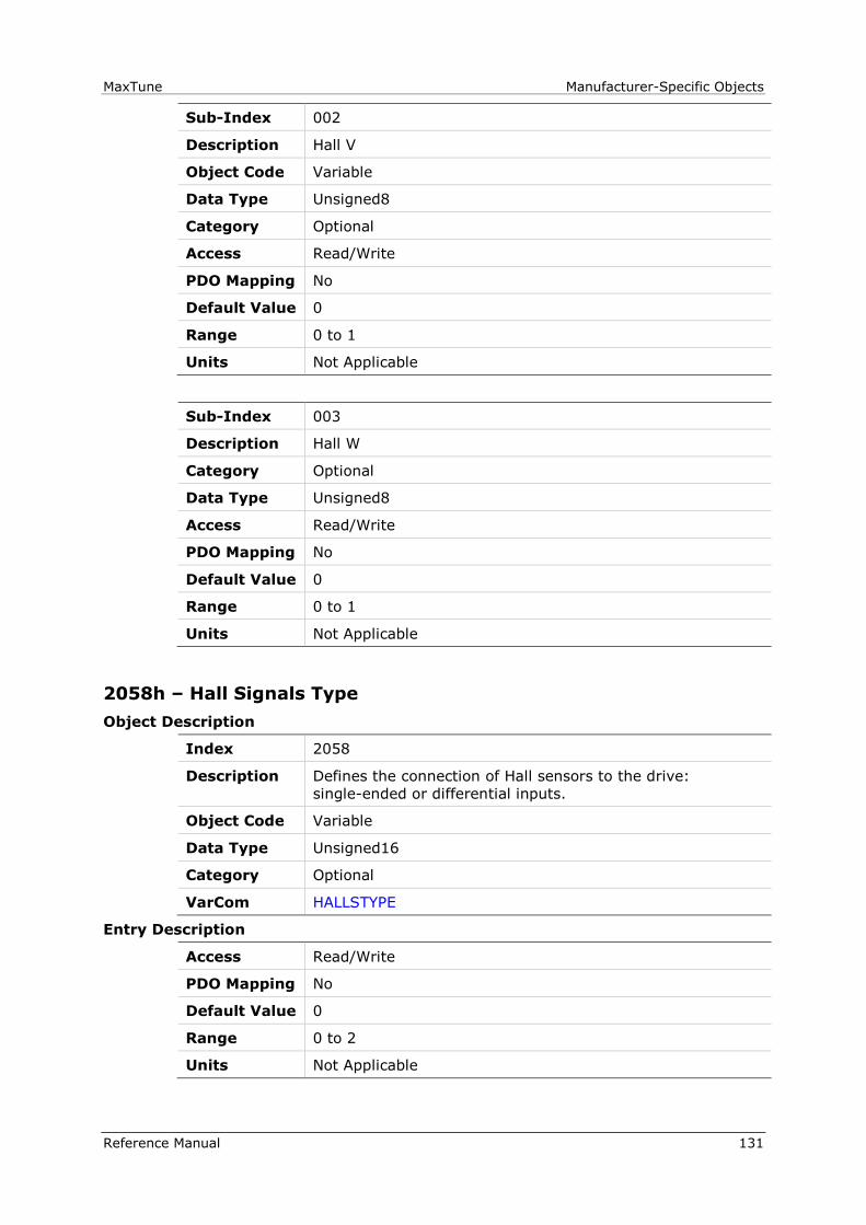
MaxTune Manufacturer-Specific Objects
Reference Manual 131
Sub-Index 002
Description Hall V
Object Code Variable
Data Type Unsigned8
Category Optional
Access Read/Write
PDO Mapping No
Default Value 0
Range 0 to 1
Units Not Applicable
Sub-Index 003
Description Hall W
Category Optional
Data Type Unsigned8
Access Read/Write
PDO Mapping No
Default Value 0
Range 0 to 1
Units Not Applicable
2058h – Hall Signals Type
Object Description
Index 2058
Description Defines the connection of Hall sensors to the drive:
single-ended or differential inputs.
Object Code Variable
Data Type Unsigned16
Category Optional
VarCom HALLSTYPE
Entry Description
Access Read/Write
PDO Mapping No
Default Value 0
Range 0 to 2
Units Not Applicable

Manufacturer-Specific Objects MaxTune
132 Reference Manual
2059h – Harmonic Correction Feedback
Object Description
Index 2059
Description Still in Development. Not intended for user unless
instructed by Technical Support.
Harmonic correction feedback
Object Code Variable
Data Type Integer32
Category Optional
VarCom HCFB
Entry Description
Access Read Only
PDO Mapping No
Default Value 0
Range -2147483648 to 2147483647
Units CAN position user units
205Ah – Harmonic Correction Feedback Parameter1
Object Description
Index 205A
Description Still in Development. Not intended for user unless
instructed by Technical Support.
Harmonic correction feedback parameter 1.
Object Code Array
Data Type Unsigned32
Category Optional
VarCom HCFB1
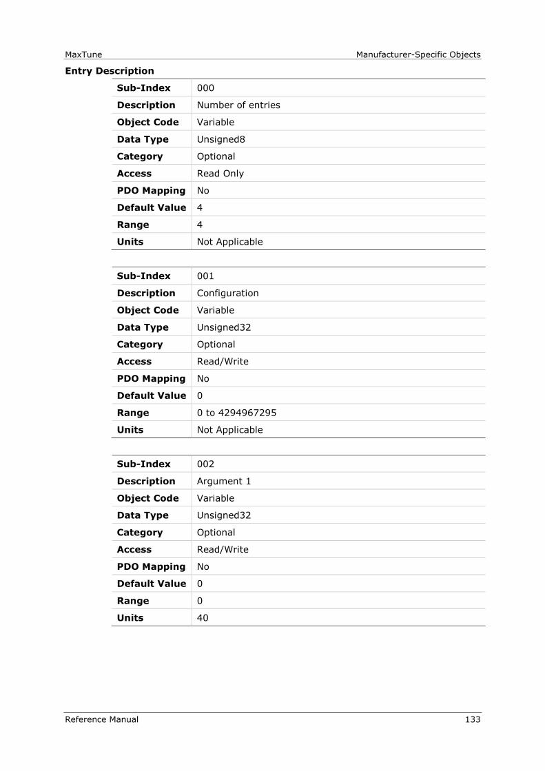
MaxTune Manufacturer-Specific Objects
Reference Manual 133
Entry Description
Sub-Index 000
Description Number of entries
Object Code Variable
Data Type Unsigned8
Category Optional
Access Read Only
PDO Mapping No
Default Value 4
Range 4
Units Not Applicable
Sub-Index 001
Description Configuration
Object Code Variable
Data Type Unsigned32
Category Optional
Access Read/Write
PDO Mapping No
Default Value 0
Range 0 to 4294967295
Units Not Applicable
Sub-Index 002
Description Argument 1
Object Code Variable
Data Type Unsigned32
Category Optional
Access Read/Write
PDO Mapping No
Default Value 0
Range 0
Units 40

Manufacturer-Specific Objects MaxTune
134 Reference Manual
Sub-Index 003
Description Argument 2
Object Code Variable
Data Type Unsigned32
Category Optional
Access Read/Write
PDO Mapping No
Default Value 0
Range 0 to 359
Units Not Applicable
Sub-Index 004
Description Argument 3
Object Code Variable
Data Type Unsigned32
Category Optional
Access Read/Write
PDO Mapping No
Default Value 0
Range 0 to 4294967295
Units CAN position user units
205Bh – Harmonic Correction Feedback Parameter 2
Object Description
Index 205B
Description Still in Development. Not intended for user unless
instructed by Technical Support.
Harmonic correction feedback parameter 2.
Object Code Array
Data Type Unsigned32
Category Optional
VarCom HCFB2
MaxTune Manufacturer-Specific Objects
Reference Manual 135
Entry Description
Sub-Index 000
Description Number of entries
Object Code Variable
Data Type Unsigned8
Category Optional
Access Read Only
PDO Mapping No
Default Value 4
Range 0 to 4
Units Not Applicable
Sub-Index 001
Description Configuration
Object Code Variable
Data Type Unsigned32
Category Optional
Access Read/Write
PDO Mapping No
Default Value 0
Range 0 to 4294967295
Units AA
Sub-Index 002
Description Argument 1
Object Code Variable
Data Type Unsigned32
Category Optional
Access Read/Write
PDO Mapping No
Default Value 0
Range 0 to 40
Units Not Applicable

Manufacturer-Specific Objects MaxTune
136 Reference Manual
Sub-Index 003
Description Argument 2
Object Code Variable
Data Type Unsigned32
Category Optional
Access Read/Write
PDO Mapping No
Default Value 0
Range 0 to 359
Units Not Applicable
Sub-Index 004
Description Argument 3
Object Code Variable
Data Type Unsigned32
Category Optional
Access Read/Write
PDO Mapping No
Default Value 0
Range 0 to 65535FFFF
Units Not Applicable

MaxTune Manufacturer-Specific Objects
Reference Manual 137
205Ch – Harmonic Correction Current
Object Description
Index 205C
Description Still in Development. Not intended for user unless
instructed by Technical Support.
Harmonic correction current.
Object Code Variable
Data Type Integer16
Category Optional
VarCom HCICMD
Entry Description
Access Read Only
PDO Mapping No
Default Value 0
Range -32768 to 32767
Units Current units

Manufacturer-Specific Objects MaxTune
138 Reference Manual
205Dh – Harmonic Current ICMD Parameter 1
Object Description
Index 205D
Description Still in Development. Not intended for user unless
instructed by Technical Support.
Harmonic correction current command parameter 1.
Object Code Record
Data Type Contains 5 fields; see sub-indices.
Category Optional
VarCom HCICMD1
Entry Description
Sub-Index 000
Description Number of entries
Object Code Variable
Data Type Unsigned8
Category Optional
Access Read Only
PDO Mapping No
Default Value 4
Range 0 to 4
Units Not Applicable
Sub-Index 001
Description Configuration
Object Code Variable
Data Type Unsigned8
Category Optional
Access Read/Write
PDO Mapping No
Default Value 0
Range 0 to 255
Units Not Applicable

MaxTune Manufacturer-Specific Objects
Reference Manual 139
Entry Description
Sub-Index 002
Description Argument 1
Object Code Variable
Data Type Unsigned16
Category Optional
Access Read/Write
PDO Mapping No
Default Value 0
Range 0 to 40
Units Not Applicable
Sub-Index 003
Description Argument 2
Object Code Variable
Data Type Unsigned16
Category Optional
Access Read/Write
PDO Mapping No
Default Value 0
Range 0 to 359
Units Not Applicable
Sub-Index 004
Description Argument 3
Object Code Variable
Data Type Real32
Category Optional
Access Read/Write
PDO Mapping No
Default Value 0.0
Range -3.40282346639e+038 to 3.40282346639e+038
Units Not Applicable
Manufacturer-Specific Objects MaxTune
140 Reference Manual
205Eh – Harmonic Current ICMD Parameter 2
Object Description
Index 205E
Description Still in Development. Not intended for user unless
instructed by Technical Support.
Harmonic correction current command parameter 2.
Object Code Record
Data Type Contains 5 fields; see sub-indices.
Category Optional
VarCom HCICMD2
Entry Description
Sub-Index 000
Description Number of entries
Object Code Variable
Data Type Unsigned8
Category Optional
Access Read Only
PDO Mapping No
Default Value 4
Range 0 to 4
Units Not Applicable
Sub-Index 001
Description Configuration
Object Code Variable
Data Type Unsigned8
Category Optional
Access Read/Write
PDO Mapping No
Default Value 0
Range 0 to 255
Units Not Applicable

MaxTune Manufacturer-Specific Objects
Reference Manual 141
Entry Description
Sub-Index 002
Description Argument 1
Object Code Variable
Data Type Unsigned16
Category Optional
Access Read/Write
PDO Mapping No
Default Value 0
Range 0 to 40
Units Not Applicable
Sub-Index 003
Description Argument 2
Object Code Variable
Data Type Unsigned16
Category Optional
Access Read/Write
PDO Mapping No
Default Value 0
Range 0 to 359
Units Not Applicable
Sub-Index 004
Description Argument 3
Object Code Variable
Data Type Real32
Category Optional
Access Read/Write
PDO Mapping No
Default Value 0.0
Range -3.40282346639e+038 to 3.40282346639e+038
Units Not Applicable
Manufacturer-Specific Objects MaxTune
142 Reference Manual
205Fh – HD Current LPF Rise Time
Object Description
Index 205F
Description HD current filter low pass filter rise time.
Object Code Variable
Data Type Real32
Category Optional
VarCom NLFILTT1
Entry Description
Access Read/Write
PDO Mapping No
Default Value 9.0
Range 0.0 to 30.0
Units milliseconds (ms)
2060h – HD Current Filter Damping
Object Description
Index 2060
Description HD current filter damping.
Object Code Variable
Data Type Integer16
Category Optional
VarCom NLFILTDAMPING
Entry Description
Access Read/Write
PDO Mapping No
Default Value 0
Range 0 to 100
Units percentage (%)

MaxTune Manufacturer-Specific Objects
Reference Manual 143
2061h – Current Notch Filter Center
Object Description
Index 2061
Description HD current filter - notch filter center.
Object Code Variable
Data Type Integer16
Category Optional
VarCom NLNOTCHCENTER
Entry Description
Access Read/Write
PDO Mapping No
Default Value 100
Range 100 to 10000
Units hertz (Hz)
2062h – HD Current Notch Filter Bandwidth
Object Description
Index 2062
Description HD current filter - notch filter bandwidth.
Object Code Variable
Data Type Integer16
Category Optional
VarCom NLNOTCHBW
Entry Description
Access Read/Write
PDO Mapping No
Default Value 0
Range 0 to 500
Units hertz (Hz)

Manufacturer-Specific Objects MaxTune
144 Reference Manual
2063h – Hold Position Command
Object Description
Index 2063
Description Instructs motor whether to maintain its position.
0 = Do not hold position
1 = Hold position
Object Code Variable
Data Type Unsigned16
Category Optional
VarCom HOLD
Entry Description
Access Read/Write
PDO Mapping No
Default Value 0
Range 0 to 1
Units Not Applicable
2064h – Hardware Position External
Object Description
Index 2064
Description The position as measured by an external feedback device.
Object Code Variable
Data Type Unsigned16
Category Optional
VarCom HWPEXT
Entry Description
Access Read Only
PDO Mapping No
Default Value 0
Range 0 to 65535
Units counts
MaxTune Manufacturer-Specific Objects
Reference Manual 145
2065h – Hardware Position
Object Description
Index 2065
Description The position (in counts) as measured by the feedback
device.
Object Code Variable
Data Type UNSIGNED64
Category Optional
VarCom HWPOS
Entry Description
Access Read Only
PDO Mapping No
Default Value 0
Range 0 to 4294967295
Units Not Applicable
2066h – Current D Axis
Object Description
Index 2066
Description In vector control, indicates the value perpendicular to 2067h
(IQ)
Object Code Variable
Data Type Integer16
Category Optional
VarCom ID
Entry Description
Access Read Only
PDO Mapping No
Default Value 0
Range -32768 to 32767
Units Current units

Manufacturer-Specific Objects MaxTune
146 Reference Manual
2067h – Current Q Axis
Object Description
Index 2067
Description In vector control, indicates the current for the torque.
This value is perpendicular to 2066h (ID).
Object Code Variable
Data Type Integer16
Category Optional
VarCom IQ
Entry Description
Access Read Only
PDO Mapping No
Default Value 0
Range -32768 to 32767
Units Current units
2068h – Current Feedforward LPF
Object Description
Index 2068
Description The corner frequency of a first-order filter of the feedforward
low pass filter.
Object Code Variable
Data Type Integer16
Category Optional
VarCom IFFLPFHZ
Entry Description
Access Read/Write
PDO Mapping No
Default Value 80
Range 10 to 1000
Units hertz (Hz)

MaxTune Manufacturer-Specific Objects
Reference Manual 147
2069h – Drive Foldback Current Limit
Object Description
Index 2069
Description The current limit derived from the foldback mechanism
Foldback condition occurs when 2069h (IFOLD) goes below
6072h (ILIM).
Object Code Variable
Data Type Integer32
Category Optional
VarCom IFOLD
Entry Description
Access Read Only
PDO Mapping No
Default Value 0
Range -2147483648 to 2147483647
Units Current units
206Ah – Drive Foldback Fault Threshold
Object Description
Index 206A
Description The current threshold for declaring a fault due to foldback.
Object Code Variable
Data Type Unsigned32
Category Optional
VarCom IFOLDFTHRESH
Entry Description
Access Read/Write
PDO Mapping No
Default Value 0
Range 0 to 4294967295
Units Current units
Manufacturer-Specific Objects MaxTune
148 Reference Manual
206Bh – Drive Foldback Warning Threshold
Object Description
Index 206B
Description The current threshold for declaring a warning due to
foldback. Threshold warning is declared when 2069h (IFOLD)
goes below 206Ah (IFOLDFTHRESH).
Object Code Variable
Data Type Unsigned32
Category Optional
VarCom IFOLDWTHRESH
Entry Description
Access Read/Write
PDO Mapping No
Default Value 0
Range 0 to 4294967295
Units Current units
206Ch – Gravity Compensation
Object Description
Index 206C
Description Value added to the current loop command to compensate for
gravity or similar constant interference.
Object Code Variable
Data Type Integer32
Category Optional
VarCom IGRAV
Entry Description
Access Read/Write
PDO Mapping No
Default Value 0
Range -2147483648 to 2147483647
Units Current units

MaxTune Manufacturer-Specific Objects
Reference Manual 149
206Dh – Encoder Index Initialization
Object Description
Index 206D
Description Detects when the encoder index is crossed and sets 202Ah
(MENCZPOS).
0 = Index not found
1 = Index found
Object Code Variable
Data Type Integer16
Category Optional
VarCom INDEXFIND
Entry Description
Access Read Only
PDO Mapping No
Default Value 0
Range -32768 to 32767
Units Not Applicable
206Eh – Encoder Initialization Status
Object Description
Index 206E
Description The state of the index search and initialization procedure
206Dh (INDEXFIND).
0 = The index search was not started.
1 = Search for index is running.
2 = Index capture is done.
Object Code Variable
Data Type Integer16
Category Optional
VarCom INDEXFINDST
Entry Description
Access Read Only
PDO Mapping No
Default Value 0
Range -32768 to 32767
Units Not Applicable
Manufacturer-Specific Objects MaxTune
150 Reference Manual
206Fh – Encoder Index Position Feedback
Object Description
Index 206F
Description The position feedback value captured at the encoder index
position.
Object Code Variable
Data Type Unsigned16
Category Optional
VarCom INDEXPFB
Entry Description
Access Read Only
PDO Mapping No
Default Value 0
Range -2147483648 to 2147483647
Units Position units
2070h – Input Inversion
Object Description
Index 2070
Description The inversion state of each digital input.
The index should be written first. Then, writing the value
executes the actual input inversion.
Object Code Array
Data Type Unsigned16
Category Optional
VarCom ININV
Entry Description
Sub-Index 000
Description Number of entries
Object Code Variable
Data Type Unsigned8
Category Optional
Access Read Only
PDO Mapping No
Default Value 2
Range 2
Units Not Applicable

MaxTune Manufacturer-Specific Objects
Reference Manual 151
Sub-Index 001
Description Index
Object Code Variable
Data Type Unsigned16
Category Optional
Access Read/Write
PDO Mapping No
Default Value 0
Range 1 to 11
Units Not Applicable
Sub-Index 002
Description Value
Object Code Variable
Data Type Unsigned16
Category Optional
Access Read/Write
PDO Mapping No
Default Value 0
Range 0 to 1
Units Not Applicable

Manufacturer-Specific Objects MaxTune
152 Reference Manual
2071h – Dynamic Brake Current
Object Description
Index 2071
Description Maximum current for dynamic braking. Limited by 207Bh
(DIPEAK).
Object Code Variable
Data Type Real32
Category Optional
VarCom ISTOP
Entry Description
Access Read/Write
PDO Mapping No
Default Value 0.0
Range 0.0 to 150.0
Units ampere (A)
2072h – Phase U Actual Current
Object Description
Index 2072
Description The actual current at phase U (of UVW).
Object Code Variable
Data Type Integer32
Category Optional
VarCom IU
Entry Description
Access Read Only
PDO Mapping No
Default Value 0
Range -2147483648 to 2147483647
Units Current units
MaxTune Manufacturer-Specific Objects
Reference Manual 153
2073h – Phase U Current Offset
Object Description
Index 2073
Description The current offset of phase U (of UVW).
Object Code Variable
Data Type Integer32
Category Optional
VarCom IUOFFSET
Entry Description
Access Read Only
PDO Mapping No
Default Value 0
Range -2147483648 to 2147483647
Units Current units
2074h – Phase V Actual Current
Object Description
Index 2074
Description The actual current at phase V (of UVW).
Object Code Variable
Data Type Integer32
Category Optional
VarCom IV
Entry Description
Access Read Only
PDO Mapping No
Default Value 0
Range -2147483648 to 2147483647
Units Current units
Manufacturer-Specific Objects MaxTune
154 Reference Manual
2075h – Phase V Current Offset
Object Description
Index 2975
Description The current offset of phase V (of UVW).
Object Code Variable
Data Type Integer32
Category Optional
VarCom IVOFFSET
Entry Description
Access Read Only
PDO Mapping No
Default Value 0
Range -2147483648 to 2147483647
Units Current units
2076h – Zero Procedure Current
Object Description
Index 2076
Description The current for the Zero procedure.
Object Code Variable
Data Type Real32
Category Optional
VarCom IZERO
Entry Description
Access Read/Write
PDO Mapping No
Default Value 1.0
Range 0.0 to 150.0
Units Not Applicable

MaxTune Manufacturer-Specific Objects
Reference Manual 155
2077h – Position Integral Saturation Input
Object Description
Index 2077
Description Position Integral Saturation Input
Object Code Variable
Data Type Real32
Category Optional
VarCom KPISATIN
Entry Description
Access Read/Write
PDO Mapping No
Default Value 0.0
Range 0.0 to 10000.0
Units Not Applicable
2078h – Negative Limit Switch Status
Object Description
Index 2078
Description The state of the hardware limit switches as configured by the
digital inputs, in the negative direction.
Object Code Variable
Data Type Unsigned16
Category Optional
VarCom LIMSWITCHNEG
Entry Description
Access Read Only
PDO Mapping No
Default Value 0
Range 0 to 1
Units Not Applicable
Manufacturer-Specific Objects MaxTune
156 Reference Manual
2079h – Positive Limit Switch Status
Object Description
Index 2079
Description The state of the hardware limit switches as configured by the
digital inputs, in the positive direction.
Object Code Variable
Data Type Unsigned16
Category Optional
VarCom LIMSWITCHPOS
Entry Description
Access Read Only
PDO Mapping No
Default Value 0
Range 0 to 1
Units Not Applicable
207Ah – Load to Motor Inertia Ratio
Object Description
Index 207A
Description The ratio of the load inertia to the motor inertia.
Object Code Variable
Data Type Real32
Category Optional
VarCom LMJR
Entry Description
Access Read/Write
PDO Mapping No
Default Value 0.0
Range 0.0 to 600.0
Units Not Applicable

MaxTune Manufacturer-Specific Objects
Reference Manual 157
207Bh – Drive Peak Current
Object Description
Index 207B
Description The peak rated current of the drive (sinusoidal peak).
Object Code Variable
Data Type Real32
Category Optional
VarCom DIPEAK
Entry Description
Access Read Only
PDO Mapping No
Default Value 0.0
Range -3.40282346639e+038 to 3.40282346639e+038
Units ampere (A)
207Ch – Drive Continuous Current
Object Description
Index 207C
Description The continuous rated current for the drive (sinusoidal peak).
Object Code Variable
Data Type Real32
Category Optional
VarCom DICONT
Entry Description
Access Read Only
PDO Mapping No
Default Value 0.0
Range -3.40282346639e+038 to 3.40282346639e+038
Units ampere (A)

Manufacturer-Specific Objects MaxTune
158 Reference Manual
207Dh – Motor Pitch
Object Description
Index 207D
Description The pitch of a linear motor.
Object Code Variable
Data Type Unsigned32
Category Optional
VarCom MPITCH
Entry Description
Access Read/Write
PDO Mapping No
Default Value 32
Range 1 to 100000
Units millimeters (mm)
207Eh – Motor Poles
Object Description
Index 207E
Description The number of individual poles (not pairs) in the motor.
Object Code Variable
Data Type Integer16
Category Optional
VarCom MPOLES
Entry Description
Access Read/Write
PDO Mapping No
Default Value 2
Range 2 to 80
Units poles

MaxTune Manufacturer-Specific Objects
Reference Manual 159
207Fh – Motor Resistance
Object Description
Index 207F
Description The motor resistance.
Object Code Variable
Data Type Real32
Category Optional
VarCom MR
Entry Description
Access Read/Write
PDO Mapping No
Default Value 0.0
Range 0.0 to 10.0
Units Ohm (Ω)
2080h – Motor Resolver Poles
Object Description
Index 2080
Description The number of individual poles in the resolver feedback
device.
Object Code Variable
Data Type Integer16
Category Optional
VarCom MRESPOLES
Entry Description
Access Read/Write
PDO Mapping No
Default Value 2
Range 2 to 80
Units poles
Manufacturer-Specific Objects MaxTune
160 Reference Manual
2081h – Motor Rated Torque
Object Description
Index 2081
Description Motor rated torque
Object Code Variable
Data Type Unsigned32
Category Optional
VarCom MRT
Entry Description
Access Read/Write
PDO Mapping No
Default Value 2000
Range 1 to 4294967295
Units millinewton meter (mNm)
2083h – Torque Commutation Angle Advance at Motor Continuous Current
Object Description
Index 2083
Description The torque-related commutation angle advance at motor
continuous current rating.
Object Code Variable
Data Type Unsigned16
Category Optional
VarCom MTANGLC
Entry Description
Access Read/Write
PDO Mapping No
Default Value 0
Range 0 to 45
Units degrees (°)
MaxTune Manufacturer-Specific Objects
Reference Manual 161
2084h – Torque Commutation Angle Advance at Motor Peak Current
Object Description
Index 2084
Description The torque-related commutation angle advance at motor
peak current.
Object Code Variable
Data Type Unsigned16
Category Optional
VarCom MTANGLP
Entry Description
Access Read/Write
PDO Mapping No
Default Value 0
Range 0 to 45
Units degrees (°)
2085h – Velocity Commutation Angle Advance at Motor Maximum
Speed
Object Description
Index 2085
Description The velocity-related commutation angle advance at motor
maximum speed.
Object Code Variable
Data Type Unsigned16
Category Optional
VarCom MVANGLF
Entry Description
Access Read/Write
PDO Mapping No
Default Value 0
Range 0 to 5
Units degrees (°)

Manufacturer-Specific Objects MaxTune
162 Reference Manual
2086h – Velocity Commutation Angle Advance at Motor Maximum
Speed/2
Object Description
Index 2086
Description The velocity-related commutation angle advance at motor
maximum speed/2.
Object Code Variable
Data Type Unsigned16
Category Optional
VarCom MVANGLH
Entry Description
Access Read/Write
PDO Mapping No
Default Value 0
Range 0 to 5
Units degrees (°)
2087h – HD Spring Filter
Object Description
Index 2087
Description HD spring filter
Object Code Variable
Data Type Unsigned16
Category Optional
VarCom NLAFFLPFHZ
Entry Description
Access Read/Write
PDO Mapping No
Default Value 7000
Range 10 to 7000
Units hertz (Hz)

MaxTune Manufacturer-Specific Objects
Reference Manual 163
2088h – PFB Backup
Object Description
Index 2088
Description PFB backup.
Reads the PFB values from non-volatile memory that were
saved by the PFB backup process.
Object Code Variable
Data Type Integer 32
Category Optional
VarCom PFBBACKUP
Entry Description
Access Read only
PDO Mapping no
Default Value 0
Range -2147483648 to 2147483647
Units CAN position user units
2089h – PFB Backup Mode
Object Description
Index 2089
Description PFB backup mode.
Enables and disables the PFB backup process.
In the event of an emergency stop, the PFB backup process
saves PFB to non-volatile memory, and restores it at the
next power up.
Object Code Variable
Data Type Unsigned integer 16
Category Optional
VarCom PFBBACKUPMODE
Entry Description
Access Read/Write
PDO Mapping No
Default Value 0
Range 0 to 1
Units Not Applicable

Manufacturer-Specific Objects MaxTune
164 Reference Manual
208Ah – HD Maximum Adaptive Gain
Object Description
Index 208A
Description HD maximum adaptive gain.
Object Code Variable
Data Type Real32
Category Optional
VarCom NLMAXGAIN
Entry Description
Access Read/Write
PDO Mapping No
Default Value 1.0
Range 1.0 to 5.0
Units Not Applicable
208Bh – HD Current Filter – Second Notch Filter Bandwidth
Object Description
Index 208B
Description HD current filter - second notch filter bandwidth
Object Code Variable
Data Type Unsigned16
Category Optional
VarCom NLNOTCH2BW
Entry Description
Access Read/Write
PDO Mapping No
Default Value 0
Range 0 to 500
Units hertz (Hz)

MaxTune Manufacturer-Specific Objects
Reference Manual 165
208Ch – HD Current Filter – Second Notch Filter Center
Object Description
Index 208C
Description HD current filter - second notch filter center
Object Code Variable
Data Type Unsigned16
Category Optional
VarCom NLNOTCH2CENTER
Entry Description
Access Read/Write
PDO Mapping No
Default Value 100
Range 100 to 10000
Units hertz (Hz)
208Fh – HD Flexibility Compensation
Object Description
Index 208F
Description HD spring gain.
Object Code Variable
Data Type Real32
Category Optional
VarCom NLPEAFF
Entry Description
Access Read/Write
PDO Mapping No
Default Value 1.0
Range 0.4 to 5.0
Units Not Applicable
Manufacturer-Specific Objects MaxTune
166 Reference Manual
2091h – HD Spring Deceleration Ratio
Object Description
Index 2091
Description HD spring deceleration ratio
Object Code Variable
Data Type Real32
Category Optional
VarCom NLPEDFFRATIO
Entry Description
Access Read/Write
PDO Mapping No
Default Value 1.0
Range 0.4 to 5.0
Units Not Applicable
2092h – HD Settling Mode
Object Description
Index 2092
Description Defines the HD settling mode.
Object Code Variable
Data Type Unsigned16
Category Optional
VarCom NLSETTLEMODE
Entry Description
Access Read/Write
PDO Mapping No
Default Value 0
Range 0 to 8
Units Not Applicable
MaxTune Manufacturer-Specific Objects
Reference Manual 167
2093h – HD Autotune Command
Object Description
Index 2093
Description Not intended for user unless instructed by Technical
Support.
Starts the HD autotuning procedure.
Object Code Variable
Data Type Unsigned16
Category Optional
VarCom NLTUNE
Entry Description
Access Read/Write
PDO Mapping No
Default Value 0
Range 0 to 3
Units Not Applicable
2094h – HD Autotune Procedure Parameter
Object Description
Index 2094
Description Not intended for user unless instructed by Technical
Support.
HD autotuning procedure parameter.
Object Code Variable
Data Type Integer32
Category Optional
VarCom NLTUNEPARAM
Entry Description
Access Not Applicable
PDO Mapping No
Default Value 0
Range -2147483648 to 2147483647
Units Position units
Manufacturer-Specific Objects MaxTune
168 Reference Manual
2097h – HD Autotune Status
Object Description
Index 2097
Description The state of the HD autotuning procedure
Object Code Variable
Data Type Visible_String
Category Optional
VarCom NLTUNEST
Entry Description
Access Read/Write
PDO Mapping No
Default Value 0
Range 0
Units Not Applicable
2098h – HD Autotune Timeout
Object Description
Index 2098
Description Not intended for user unless instructed by Technical
Support.
Timeout of the HD autotuning procedure.
Object Code Variable
Data Type Unsigned32
Category Optional
VarCom NLTUNETIME
Entry Description
Access Read/Write
PDO Mapping No
Default Value 0
Range 0 to 20000
Units millisecond (ms)
MaxTune Manufacturer-Specific Objects
Reference Manual 169
2099h – Current Level 1 for Digital Output Definition
Object Description
Index 2099
Description The first current value for a condition that controls a digital
output.
Object Code Variable
Data Type Real32
Category Optional
VarCom OUTILVL1
Entry Description
Access Read/Write
PDO Mapping No
Default Value 0.0
Range 0.0 to 150.0
Units ampere (A)
209Ah – Current Level 2 for Digital Output Definition
Object Description
Index 209A
Description The second current value for a condition that controls a
digital output.
Object Code Variable
Data Type Real32
Category Optional
VarCom OUTILVL2
Entry Description
Access Read/Write
PDO Mapping No
Default Value 0.0
Range 0.0 to 150.0
Units ampere (A)

Manufacturer-Specific Objects MaxTune
170 Reference Manual
209Bh – Output Inversion
Object Description
Index 209B
Description The inversion state of each digital output.
The index should be written first. Then, writing the value
executes the actual output inversion.
Object Code Array
Data Type Unsigned16
Category Optional
VarCom OUTINV
Entry Description
Sub-Index 000
Description Number of entries
Object Code Variable
Data Type Unsigned8
Category Optional
Access Read Only
PDO Mapping No
Default Value 2
Range 2
Units Not Applicable
Sub-Index 001
Description Index
Object Code Variable
Data Type Unsigned16
Category Optional
Access Read/Write
PDO Mapping No
Default Value 1
Range 1 to 7
Units Not Applicable
MaxTune Manufacturer-Specific Objects
Reference Manual 171
Sub-Index 002
Description Value
Object Code Variable
Data Type Unsigned16
Category Optional
Access Read/Write
PDO Mapping No
Default Value 0
Range 0 to 1
Units Not Applicable

Manufacturer-Specific Objects MaxTune
172 Reference Manual
209Ch – Output Mode
Object Description
Index 209C
0 = Idle
1 = Active (enabled)
2 = Brake
3 = Fault exists (alarm)
4 = In position
5 = Stopped
6 = Foldback
7 = Current level
8 = Current range
9 = Velocity level
10 = Velocity range
11 = Position level
12 = Position range
13 = Battery low voltage warning
14 = Warning on
15 = Faults or disabled
16 = Battery low voltage fault
17 = Phase Find OK
18 = Over-current fault
19 = Over-voltage fault
20 = Under-voltage fault
21 = Phase Find failed
22= Alarm without Phase Find failed
Object Code Array
Data Type Unsigned16
Category Optional
VarCom OUTMODE
Entry Description
Sub-Index 000
Description Number of entries
Object Code Variable
Data Type Unsigned8
Category Optional
Access Read Only
PDO Mapping No
Default Value 2
Range 2
Units Not Applicable
MaxTune Manufacturer-Specific Objects
Reference Manual 173
Sub-Index 001
Description Output index
Object Code Variable
Data Type Unsigned16
Category Optional
Access Read/Write
PDO Mapping No
Default Value 1
Range 1
Units Not Applicable
Sub-Index 002
Description Function code
Object Code Variable
Data Type Unsigned16
Category Optional
Access Read/Write
PDO Mapping No
Default Value 0
Range 0
Units Not Applicable
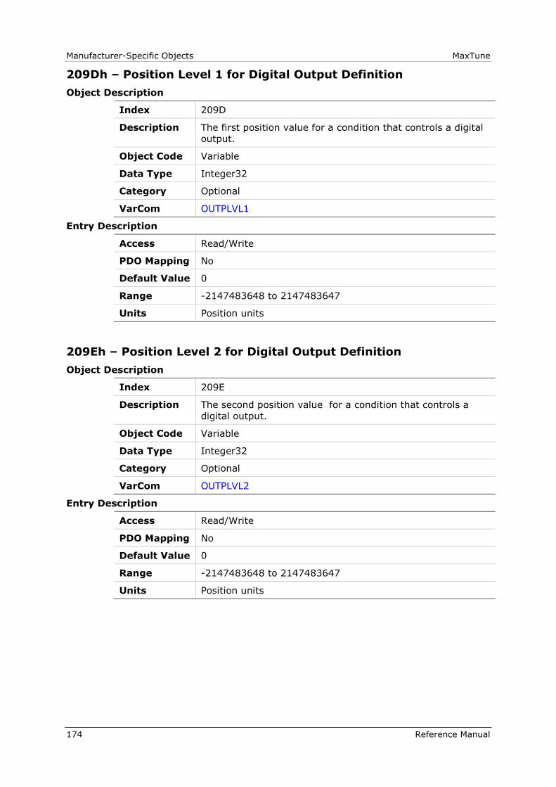
Manufacturer-Specific Objects MaxTune
174 Reference Manual
209Dh – Position Level 1 for Digital Output Definition
Object Description
Index 209D
Description The first position value for a condition that controls a digital
output.
Object Code Variable
Data Type Integer32
Category Optional
VarCom OUTPLVL1
Entry Description
Access Read/Write
PDO Mapping No
Default Value 0
Range -2147483648 to 2147483647
Units Position units
209Eh – Position Level 2 for Digital Output Definition
Object Description
Index 209E
Description The second position value for a condition that controls a
digital output.
Object Code Variable
Data Type Integer32
Category Optional
VarCom OUTPLVL2
Entry Description
Access Read/Write
PDO Mapping No
Default Value 0
Range -2147483648 to 2147483647
Units Position units
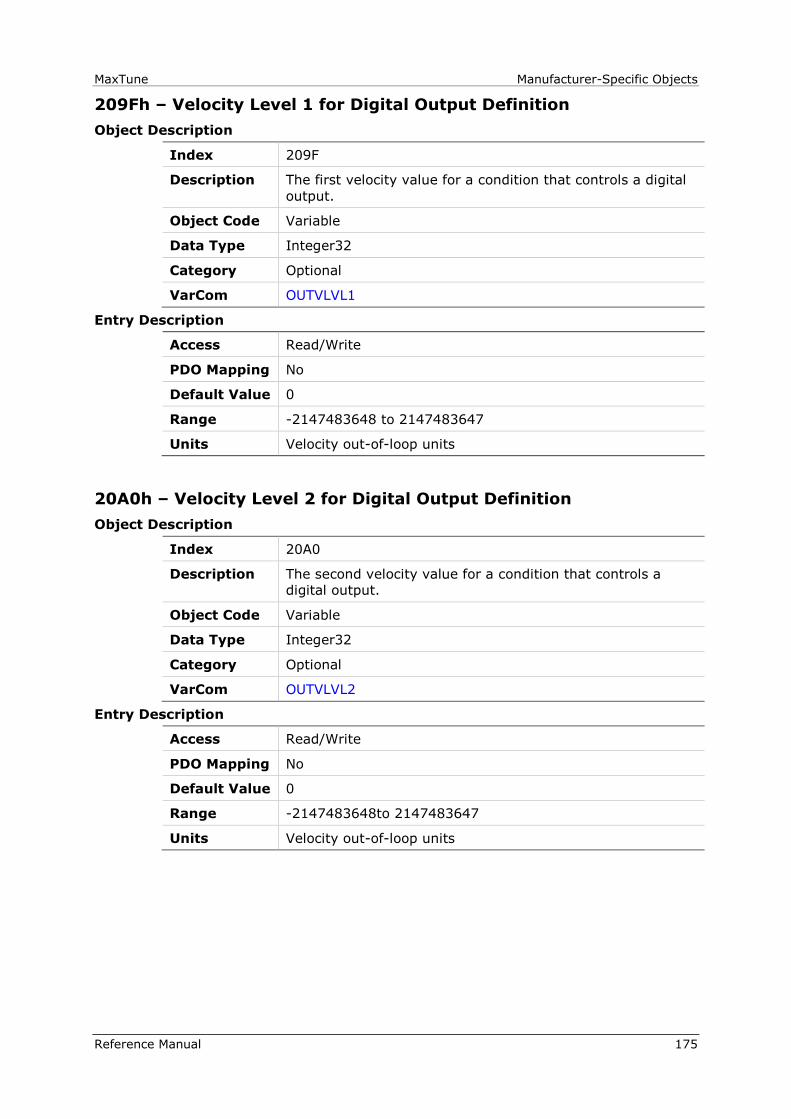
MaxTune Manufacturer-Specific Objects
Reference Manual 175
209Fh – Velocity Level 1 for Digital Output Definition
Object Description
Index 209F
Description The first velocity value for a condition that controls a digital
output.
Object Code Variable
Data Type Integer32
Category Optional
VarCom OUTVLVL1
Entry Description
Access Read/Write
PDO Mapping No
Default Value 0
Range -2147483648 to 2147483647
Units Velocity out-of-loop units
20A0h – Velocity Level 2 for Digital Output Definition
Object Description
Index 20A0
Description The second velocity value for a condition that controls a
digital output.
Object Code Variable
Data Type Integer32
Category Optional
VarCom OUTVLVL2
Entry Description
Access Read/Write
PDO Mapping No
Default Value 0
Range -2147483648to 2147483647
Units Velocity out-of-loop units
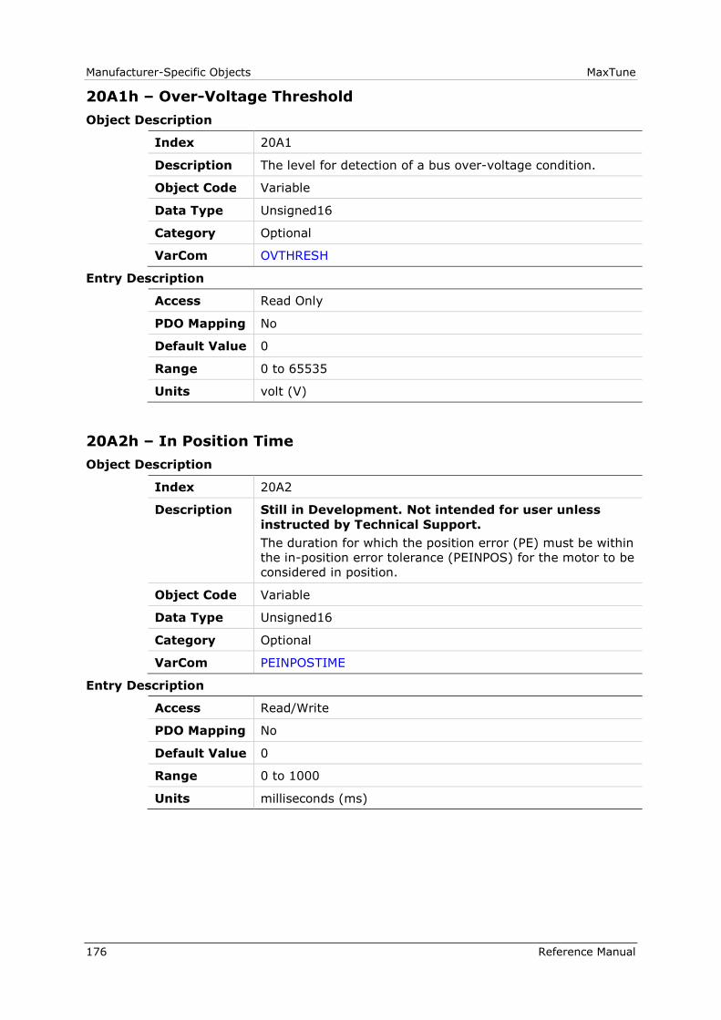
Manufacturer-Specific Objects MaxTune
176 Reference Manual
20A1h – Over-Voltage Threshold
Object Description
Index 20A1
Description The level for detection of a bus over-voltage condition.
Object Code Variable
Data Type Unsigned16
Category Optional
VarCom OVTHRESH
Entry Description
Access Read Only
PDO Mapping No
Default Value 0
Range 0 to 65535
Units volt (V)
20A2h – In Position Time
Object Description
Index 20A2
Description Still in Development. Not intended for user unless
instructed by Technical Support.
The duration for which the position error (PE) must be within
the in-position error tolerance (PEINPOS) for the motor to be
considered in position.
Object Code Variable
Data Type Unsigned16
Category Optional
VarCom PEINPOSTIME
Entry Description
Access Read/Write
PDO Mapping No
Default Value 0
Range 0 to 1000
Units milliseconds (ms)
MaxTune Manufacturer-Specific Objects
Reference Manual 177
20A3h – Position Loop Position Error
Object Description
Index 20A3
Description Position error value used by the position loop.
Object Code Variable
Data Type Integer32
Category Optional
VarCom PELOOP
Entry Description
Access Read Only
PDO Mapping No
Default Value 0
Range -2147483648 to 2147483647
Units Position units
20A4h – Phase Find Command
Object Description
Index 20A4
Description Starts a procedure that initializes commutation for
incremental encoder systems.
Writing 1 initiates the Phase Find command.
Object Code Variable
Data Type Unsigned8
Category Optional
VarCom PHASEFIND
Entry Description
Access Read/Write
PDO Mapping No
Default Value 0
Range 0 to 1
Units Not Applicable

Manufacturer-Specific Objects MaxTune
178 Reference Manual
20A5h – Forced Electrical Position
Object Description
Index 20A5
Description The position in one revolution.
Object Code Variable
Data Type Unsigned16
Category Optional
VarCom PHASEFINDANGLE
Entry Description
Access Read/Write
PDO Mapping No
Default Value 0
Range 0 to 65535
Units 65536/electrical cycle
20A6h – Phase Find Gain
Object Description
Index 20A6
Description Adjusts the gain of the phase finding mechanism.
Object Code Variable
Data Type Real32
Category Optional
VarCom PHASEFINDGAIN
Entry Description
Access Read/Write
PDO Mapping No
Default Value 1.0
Range 0.0 to 10.0
Units Not Applicable
MaxTune Manufacturer-Specific Objects
Reference Manual 179
20A7h – Phase Find Current
Object Description
Index 20A7
Description Adjusts the current of the phase finding mechanism.
Limited by 6073h (IMAX).
Object Code Variable
Data Type Real32
Category Optional
VarCom PHASEFINDI
Entry Description
Access Read/Write
PDO Mapping N0
Default Value 0.0
Range 0.0 to 150.0
Units ampere (A)
20A8h – Phase Find Mode
Object Description
Index 20A8
Description Defines commutation for phase finding.
0 = Injects test signals and analyzes motor behavior to
initialize commutation.
2 = Soft start - increases current at a known commutation
angle (wake-no-shake).
11 = Manual commutation offset. Commutation offset is
defined by the value of 20A5h (PHASEFINDANGLE).
Object Code Variable
Data Type Unsigned16
Category Optional
VarCom PHASEFINDMODE
Entry Description
Access Read/Write
PDO Mapping No
Default Value 0
Range 0 to 11
Units Not Applicable
Manufacturer-Specific Objects MaxTune
180 Reference Manual
20A9h – Phase Find Status
Object Description
Index 20A9
Description The state of the phase finding procedure for incremental
encoders.
0 = Not started
1 = Running
2 = Succeeded
3 = Failed
Object Code Variable
Data Type Unsigned16
Category Optional
VarCom PHASEFINDST
Entry Description
Access Read Only
PDO Mapping No
Default Value 0
Range 0 to 65535
Units Not Applicable
20AAh – Phase Find Duration
Object Description
Index 20AA
Description Limits the duration of phase finding 20A8h
(PHASEFINDMODE) in soft start mode (input 2).
Object Code Variable
Data Type Unsigned16
Category Optional
VarCom PHASEFINDTIME
Entry Description
Access Read/Write
PDO Mapping No
Default Value 100
Range 0 to 10000
Units milliseconds (ms)

MaxTune Manufacturer-Specific Objects
Reference Manual 181
20ABh – Position Loop Controller Mode
Object Description
Index 20AB
Description Defines the type of position loop controller.
0 = Standard cascaded position controller.
1 = HD position controller .
Object Code Variable
Data Type Unsigned16
Category Optional
VarCom POSCONTROLMODE
Entry Description
Access Read/Write
PDO Mapping No
Default Value 0
Range 0 to 1
Units Not Applicable
20ACh – Software Position Limit Mode
Object Description
Index 20AC
Description Enables/disables software position limits.
Object Code Variable
Data Type Unsigned16
Category Optional
VarCom POSLIMMODE
Entry Description
Access Read/Write
PDO Mapping No
Default Value 0
Range 0 to 1
Units Not Applicable

Manufacturer-Specific Objects MaxTune
182 Reference Manual
20ADh – PRB Generator Frequency
Object Description
Index 20AD
Description Defines the frequency for PRB excitation.
For pseudo binary noise (208Fh sub-index 1 = 0, 1), this
object has no effect.
For sine and square wave generators
(208Fh sub-index 1 = 2 or 208Fh sub-index 1 = 3), this
object defines the frequency of the sine and square wave
generator, respectively.
Object Code Variable
Data Type Real32
Category Optional
VarCom PRBFRQ
Entry Description
Access Read/Write
PDO Mapping No
Default Value 100.0
Range 0.10000000149 to 5000.0
Units hertz (Hz)
20AEh – PRB Generator Mode
Object Description
Index 20AE
Description Defines if and how the PRB signal generator is activated:
0 = PRB generator not activated
1 = PRB generator activated only during recording
2 = PRB generator activated continuously
Object Code Variable
Data Type Unsigned16
Category Optional
VarCom PRBMODE
Entry Description
Access Read/Write
PDO Mapping No
Default Value 0
Range 0 to 2
Units Not Applicable
MaxTune Manufacturer-Specific Objects
Reference Manual 183
20AFh – PRB Generator Configuration
Object Description
Index 20AF
Description Not intended for user unless instructed by Technical
Support.
PRB generator configuration.
Signal Type:
0 - 8 bit random noise
1 - 10 bit random noise
2 - sine wave
3 - square wave
Current Amplitude is limited with the Max Current (6073h).
Velocity Amplitude is limited with the Max Profile Velocity
(607Fh).
Counter Period is relative to current loop update rate.
Object Code Record
Data Type PRB_PAR
Category Optional
VarCom PRBPARAM
Entry Description
Sub-Index 000
Description Number of entries
Object Code Variable
Data Type Unsigned8
Category Optional
Access Read Only
PDO Mapping No
Default Value 5
Range 5
Units Not Applicable

Manufacturer-Specific Objects MaxTune
184 Reference Manual
Sub-Index 001
Description Signal type
Object Code Variable
Data Type Unsigned16
Category Optional
Access Read/Write
PDO Mapping No
Default Value 0
Range 0 to 3
Units Not Applicable
Sub-Index 002
Description Current Amplitude
Object Code Variable
Data Type Integer32
Category Optional
Access Read/Write
PDO Mapping No
Default Value 0
Range 80000000h to 7FFFFFFFh
Units Current units
Sub-Index 003
Description Velocity amplitude
Object Code Variable
Data Type Integer32
Category Optional
Access Read/Write
PDO Mapping No
Default Value 0
Range 80000000h to 7FFFFFFFh
Units Velocity units
MaxTune Manufacturer-Specific Objects
Reference Manual 185
Sub-Index 004
Description Counter period
Object Code Variable
Data Type Unsigned16
Category Optional
Access Read/Write
PDO Mapping No
Default Value 0
Range 0 to 65535
Units Not Applicable
Sub-Index 005
Description Configuration
Object Code Variable
Data Type Unsigned16
Category Optional
Access Read/Write
PDO Mapping No
Default Value 0
Range 0 to 1
Units Not Applicable
Manufacturer-Specific Objects MaxTune
186 Reference Manual
20B0h – PTP Generator Target Error
Object Description
Index 20B0
Description The target error during a motion profile (the distance
remaining to the destination in a point-to-point move).
Object Code Variable
Data Type Integer32
Category Optional
VarCom PTPTE
Entry Description
Access Read Only
PDO Mapping No
Default Value 0
Range -2147483648 to 2147483647
Units Position units
20B1h – PTP Generator Velocity Command
Object Description
Index 20B1
Description The derivative of the position command profile, in velocity
units.
Object Code Variable
Data Type Integer32
Category Optional
VarCom PTPVCMD
Entry Description
Access Read Only
PDO Mapping No
Default Value 0
Range -2147483648 to 2147483647
Units Velocity units

MaxTune Manufacturer-Specific Objects
Reference Manual 187
20B2h – PWM Frequency
Object Description
Index 20B2
Description The frequency of the PWM signals.
Object Code Variable
Data Type Real32
Category Optional
VarCom PWMFRQ
Entry Description
Access Read Only
PDO Mapping No
Default Value 0.0
Range -3.40282346639e+038 to 3.40282346639e+038
Units kilohertz (kHz)
20B4h – PWM Saturation Ratio
Object Description
Index 20B4
Description The duration of current saturation within a commutation
cycle.
Object Code Variable
Data Type Real32
Category Optional
VarCom PWMSATRATIO
Entry Description
Access Read/Write
PDO Mapping No
Default Value 1.5
Range 0.5 to 1.5
Units Not Applicable

Manufacturer-Specific Objects MaxTune
188 Reference Manual
20B8h – Fault Relay Status
Object Description
Index 20B8
Description The state of the fault relay.
0 = Relay open
1 = Relay closed
Object Code Variable
Data Type Unsigned16
Category Optional
VarCom RELAY
Entry Description
Access Read Only
PDO Mapping No
Default Value 0
Range 0 to 65535
Units Not Applicable
20B9h – Fault Relay Mode
Object Description
Index 20B9
Description Defines how the fault relay operates.
0 = Relay opens upon fault.
1 = Relay opens upon disable.
Object Code Variable
Data Type Unsigned16
Category Optional
VarCom RELAYMODE
Entry Description
Access Read/Write
PDO Mapping No
Default Value 0
Range 0 to 1
Units Not Applicable
MaxTune Manufacturer-Specific Objects
Reference Manual 189
20BAh – Remote Hardware Enable Status
Object Description
Index 20BA
Description Indicates the state of the external hardware enable input.
0 = Remote enable input off.
1 = Remote enable input on.
Object Code Variable
Data Type Unsigned16
Category Optional
VarCom REMOTE
Entry Description
Access Read Only
PDO Mapping No
Default Value 0
Range 0 to 65535
Units Not Applicable
20BBh – Resolver Amplitude Range
Object Description
Index 20BB
Description The acceptable range of deviation of resolver sine/cosine
signals (as a percentage).
Object Code Variable
Data Type Unsigned16
Category Optional
VarCom RESAMPLRANGE
Entry Description
Access Read/Write
PDO Mapping No
Default Value 35
Range 0 to 100
Units percentage (%)
Manufacturer-Specific Objects MaxTune
190 Reference Manual
20BCh – Resolver Conversion Bandwidth
Object Description
Index 20BC
Description Resolver conversion bandwidth.
Object Code Variable
Data Type Unsigned16
Category Optional
VarCom RESBW
Entry Description
Access Read/Write
PDO Mapping No
Default Value 300
Range 200 to 800
Units hertz (Hz)
20BDh – Save Parameters
Object Description
Index 20BD
Description Copies all system configuration variables from working RAM
to non-volatile memory.
Writing 01 initiates the command.
This command requires a response timeout of at least
1000 ms.
Object Code Variable
Data Type Unsigned8
Category Optional
VarCom SAVE
Entry Description
Access Read/Write
PDO Mapping No
Default Value 0
Range 0 to 1
Units Not Applicable
MaxTune Manufacturer-Specific Objects
Reference Manual 191
20BEh – Sine/Cosine Calibration Command
Object Description
Index 20BE
Description Activates a procedure that calibrates the resolver sine/cosine
signals.
Object Code Variable
Data Type Unsigned16
Category Optional
VarCom SININIT
Entry Description
Access Read/Write
PDO Mapping No
Default Value 0
Range 0 to 1
Units Not Applicable
Manufacturer-Specific Objects MaxTune
192 Reference Manual
20BFh – Sine/Cosine Calibration Mode
Object Description
Index 20BF
Description Enables/disables automatic calibration of sine/cosine signals.
Object Code Variable
Data Type Unsigned16
Category Optional
VarCom SININITMODE
Entry Description
Access Read/Write
PDO Mapping No
Default Value 0
Range 0 to 1
Units Not Applicable
20C0h – Sine/Cosine Calibration Status
Object Description
Index 20C0
Description The state of resolver calibration procedure.
Object Code Variable
Data Type Unsigned16
Category Optional
VarCom SININITST
Entry Description
Access Read Only
PDO Mapping No
Default Value 0
Range 0 to 65535
Units Not Applicable
MaxTune Manufacturer-Specific Objects
Reference Manual 193
20C1h – Sine/Cosine Calibration Parameters
Object Description
Index 20C1
Description Returns the parameters for calibration of the resolver sine
and cosine signals.
Object Code Variable
Data Type Visible_String
Category Optional
VarCom SINPARAM
Entry Description
Access Read Only
PDO Mapping No
Default Value 0
Range 0
Units Not Applicable
20C2h – Synchronization Mode
Object Description
Index 20C2
Description Defines the method used to synchronize the drive clock to an
external sync signal:
0 = Disabled; no sync
1 = Sync drive clock to controller based on fast digital
input 5
2 = Sync drive clock to controller based on fast digital
input 6
3 = Sync drive clock based on pulse differential input
(Pulse & Direction)
Object Code Variable
Data Type Unsigned16
Category Optional
VarCom SYNCSOURCE
Entry Description
Access Read/Write
PDO Mapping No
Default Value 0
Range 0 to 5
Units Not Applicable

Manufacturer-Specific Objects MaxTune
194 Reference Manual
20C3h – Tracking Factor
Object Description
Index 20C3
Description The derivative factor for tracking with PDFF velocity
controller.
Object Code Variable
Data Type Unsigned16
Category Optional
VarCom TF
Entry Description
Access Read/Write
PDO Mapping No
Default Value 100
Range 0 to 200
Units percentage (%)
20C4h – Motor Over-Temperature
Object Description
Index 20C4
Description The state of the motor thermostat input that indicates an
over-temperature condition:
0 = Thermostat input closed (normal) or ignored, when
20C6h (THERMODE) = 3
1 = Thermostat input open, indicating overheating
Object Code Variable
Data Type Unsigned16
Category Optional
VarCom THERM
Entry Description
Access Read Only
PDO Mapping No
Default Value 0
Range 0 to 65535
Units Not Applicable

MaxTune Manufacturer-Specific Objects
Reference Manual 195
20C5h – Motor Over-Temperature Clear Fault Level
Object Description
Index 20C5
Description The level at which a motor over-temperature fault is cleared.
Object Code Variable
Data Type Unsigned32
Category Optional
VarCom THERMCLEARLEVEL
Entry Description
Access Read/Write
PDO Mapping No
Default Value 100
Range 0 to 1000000
Units Ohm (Ω)
20C6h – Motor Over-Temperature Mode
Object Description
Index 20C6
Description Defines how the drive will respond to an over-temperature
fault:
0 = Disable drive immediately.
3 = Ignore thermostat input.
4 = Issue warning only.
5 = Issue warning; if condition persists after 20C8h
(THERMTIME), issue fault.
Object Code Variable
Data Type Unsigned16
Category Optional
VarCom THERMODE
Entry Description
Access Read/Write
PDO Mapping No
Default Value 0
Range 0 to 5
Units Not Applicable

Manufacturer-Specific Objects MaxTune
196 Reference Manual
20C7h – Motor Temperature
Object Description
Index 20C7
Description The motor temperature.
Object Code Variable
Data Type Integer32
Category Optional
VarCom THERMREADOUT
Entry Description
Access Read Only
PDO Mapping No
Default Value 0
Range -2147483648 to 2147483647
Units Ohm (Ω)
20C8h – Motor Over-Temperature Time
Object Description
Index 20C8
Description The number of seconds after detection of motor
over-temperature until the drive opens the fault relay.
Object Code Variable
Data Type Unsigned16
Category Optional
VarCom THERMTIME
Entry Description
Access Read/Write
PDO Mapping No
Default Value 30
Range 0 to 300
Units seconds (s)

MaxTune Manufacturer-Specific Objects
Reference Manual 197
20C9h – Motor Over-Temperature Fault Level
Object Description
Index 20C9
Description The motor over-temperature fault level.
Object Code Variable
Data Type Unsigned32
Category Optional
VarCom THERMTRIPLEVEL
Entry Description
Access Read/Write
PDO Mapping No
Default Value 150
Range 0 to 1000000
Units Ohm (Ω)
20CAh – Motor Over-Temperature Type
Object Description
Index 20CA
Description The type of motor temperature sensor:
0 = Positive temperature coefficient (PTC)
1 = Negative temperature coefficient (NTC)
Object Code Variable
Data Type Unsigned16
Category Optional
VarCom THERMTYPE
Entry Description
Access Read/Write
PDO Mapping No
Default Value 0
Range 0 to 1
Units Not Applicable
Manufacturer-Specific Objects MaxTune
198 Reference Manual
20CBh – Tamagawa Multi-Turn Reset
Object Description
Index 20CB
Description Resets the counter of a Tamagawa multi-turn encoder.
Writing 01 initiates the command.
Object Code Variable
Data Type Unsigned8
Category Optional
VarCom TMTURNRESET
Entry Description
Access Read/Write
PDO Mapping No
Default Value 0
Range 0 to 1
Units Not Applicable
20CCh – Run Time
Object Description
Index 20CC
Description The total elapsed run time of the drive since production
(cannot be reset).
Object Code Variable
Data Type Visible_String
Category Optional
VarCom TRUN
Entry Description
Access Read Only
PDO Mapping No
Default Value 0
Range 0
Units Not Applicable
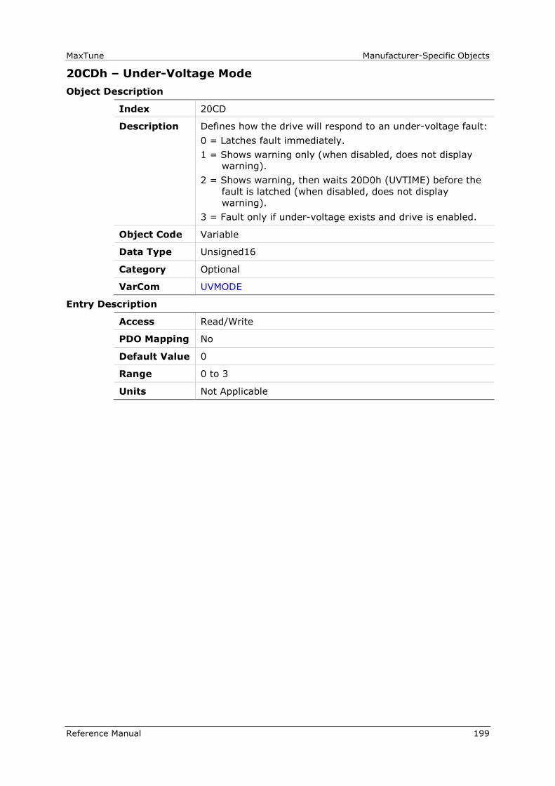
MaxTune Manufacturer-Specific Objects
Reference Manual 199
20CDh – Under-Voltage Mode
Object Description
Index 20CD
Description Defines how the drive will respond to an under-voltage fault:
0 = Latches fault immediately.
1 = Shows warning only (when disabled, does not display
warning).
2 = Shows warning, then waits 20D0h (UVTIME) before the
fault is latched (when disabled, does not display
warning).
3 = Fault only if under-voltage exists and drive is enabled.
Object Code Variable
Data Type Unsigned16
Category Optional
VarCom UVMODE
Entry Description
Access Read/Write
PDO Mapping No
Default Value 0
Range 0 to 3
Units Not Applicable
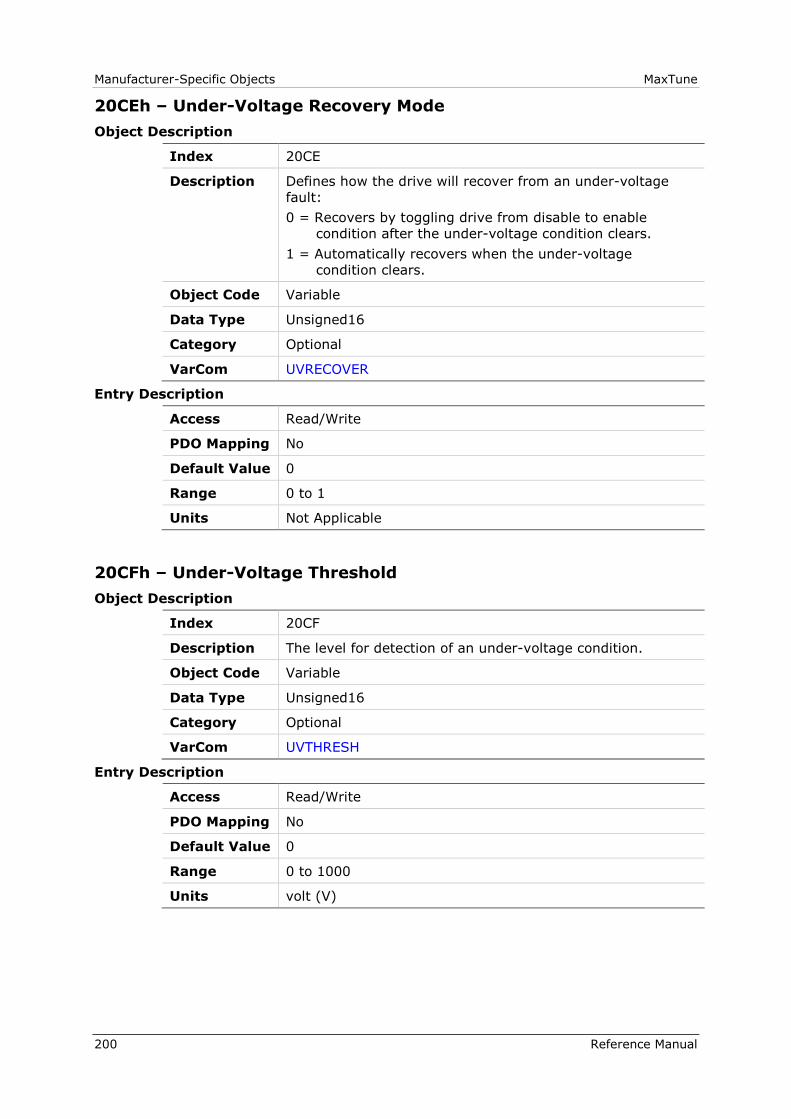
Manufacturer-Specific Objects MaxTune
200 Reference Manual
20CEh – Under-Voltage Recovery Mode
Object Description
Index 20CE
Description Defines how the drive will recover from an under-voltage
fault:
0 = Recovers by toggling drive from disable to enable
condition after the under-voltage condition clears.
1 = Automatically recovers when the under-voltage
condition clears.
Object Code Variable
Data Type Unsigned16
Category Optional
VarCom UVRECOVER
Entry Description
Access Read/Write
PDO Mapping No
Default Value 0
Range 0 to 1
Units Not Applicable
20CFh – Under-Voltage Threshold
Object Description
Index 20CF
Description The level for detection of an under-voltage condition.
Object Code Variable
Data Type Unsigned16
Category Optional
VarCom UVTHRESH
Entry Description
Access Read/Write
PDO Mapping No
Default Value 0
Range 0 to 1000
Units volt (V)
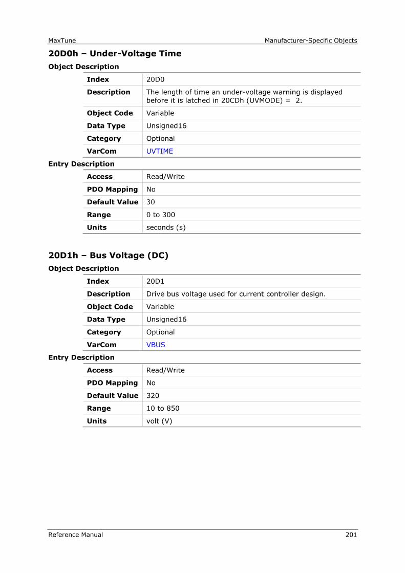
MaxTune Manufacturer-Specific Objects
Reference Manual 201
20D0h – Under-Voltage Time
Object Description
Index 20D0
Description The length of time an under-voltage warning is displayed
before it is latched in 20CDh (UVMODE) = 2.
Object Code Variable
Data Type Unsigned16
Category Optional
VarCom UVTIME
Entry Description
Access Read/Write
PDO Mapping No
Default Value 30
Range 0 to 300
Units seconds (s)
20D1h – Bus Voltage (DC)
Object Description
Index 20D1
Description Drive bus voltage used for current controller design.
Object Code Variable
Data Type Unsigned16
Category Optional
VarCom VBUS
Entry Description
Access Read/Write
PDO Mapping No
Default Value 320
Range 10 to 850
Units volt (V)

Manufacturer-Specific Objects MaxTune
202 Reference Manual
20D3h – Velocity Error
Object Description
Index 20D3
Description The velocity error of velocity loop.
Object Code Variable
Data Type Integer32
Category Optional
VarCom VE
Entry Description
Access Read Only
PDO Mapping No
Default Value 0
Range -2147483648 to 2147483647
Units Velocity in-loop units

MaxTune Manufacturer-Specific Objects
Reference Manual 203
20D4h – Velocity Loop Controller
Object Description
Index 20D4
Description Defines the type of velocity loop controller:
0 = PI controller: uses 2026h (KVP), 2027h (KVI)
1 = PDFF controller: uses 2025h (KVP), 2026h (KVI), 2027h
(KVFR)
2 = Standard pole placement controller: uses 2037h (MJ),
2039h (MKT), 2010h (BW), 207Ah (LMJR), 20C3h (TF)
3 = Extended polynomial controller: uses 20DBh (VR),
20DAh (VH), 20D8h (VF), and VarCom VD. – Still in
development.
4 = High frequency pole placement controller: (uses 2037h
(MJ), 2039h (MKT), 2010h (BW), 207Ah (LMJR), 20C3h
(TF)
5 = HD velocity control with integrator: 2018h (KNLI),
2019h (KNLIV)
6 = HD velocity control without integrator
Object Code Variable
Data Type Unsigned8
Category Optional
VarCom VELCONTROLMODE
Entry Description
Access Read/Write
PDO Mapping No
Default Value 0
Range 0 to 6
Units Not Applicable

Manufacturer-Specific Objects MaxTune
204 Reference Manual
20D5h – Velocity Design Structure
Object Description
Index 20D5
Description Velocity design structure.
Returns a conversion of the internal velocity controller as set
by one of the standard velocity control modes to a general
extended polynomial controller structure.
Applicable only to standard cascaded position controller:
Position Loop Controller Mode (20ABh) = 0.
Object Code Variable
Data Type Visible_String
Category Optional
VarCom VELDESIGN
Entry Description
Access Read Only
PDO Mapping No
Default Value 0
Range 0
Units Not Applicable
20D6h – Velocity Filter Mode
Object Description
Index 20D6
Description The type of filter for extracting a velocity signal from the
position feedback:
0 = No filter
1 = First order filter
2 = Observer type I
3 = Observer type II
Object Code Variable
Data Type Unsigned16
Category Optional
VarCom VELFILTMODE
Entry Description
Access Read/Write
PDO Mapping No
Default Value 1
Range 0 to 3
Units Not Applicable
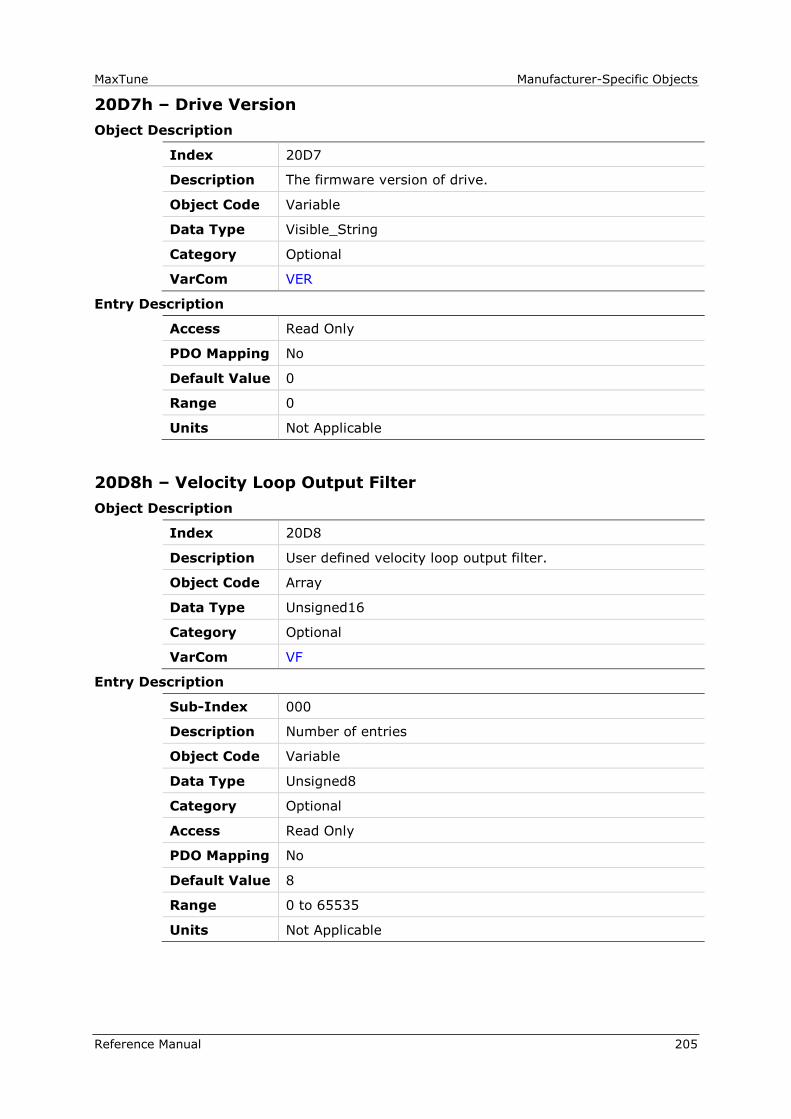
MaxTune Manufacturer-Specific Objects
Reference Manual 205
20D7h – Drive Version
Object Description
Index 20D7
Description The firmware version of drive.
Object Code Variable
Data Type Visible_String
Category Optional
VarCom VER
Entry Description
Access Read Only
PDO Mapping No
Default Value 0
Range 0
Units Not Applicable
20D8h – Velocity Loop Output Filter
Object Description
Index 20D8
Description User defined velocity loop output filter.
Object Code Array
Data Type Unsigned16
Category Optional
VarCom VF
Entry Description
Sub-Index 000
Description Number of entries
Object Code Variable
Data Type Unsigned8
Category Optional
Access Read Only
PDO Mapping No
Default Value 8
Range 0 to 65535
Units Not Applicable

Manufacturer-Specific Objects MaxTune
206 Reference Manual
Sub-Index 001
Description Velocity loop output filter parameter 1
Object Code Variable
Data Type Unsigned16
Category Optional
Access Read/Write
PDO Mapping No
Default Value 0
Range 0 to 65535
Units Not Applicable
Sub-Index 002
Description Velocity loop output filter parameter 2
Object Code Variable
Data Type Unsigned16
Category Optional
Access Read/Write
PDO Mapping No
Default Value 0
Range 0 to 65535
Units Not Applicable
Sub-Index 003
Description Velocity loop output filter parameter 3
Object Code Variable
Data Type Unsigned16
Category Optional
Access Read/Write
PDO Mapping No
Default Value 0
Range 0 to 65535
Units Not Applicable

MaxTune Manufacturer-Specific Objects
Reference Manual 207
Sub-Index 004
Description Velocity loop output filter parameter 4
Object Code Variable
Data Type Unsigned16
Category Optional
Access Read/Write
PDO Mapping No
Default Value 0
Range 0 to 65535
Units Not Applicable
Sub-Index 005
Description Velocity loop output filter parameter 5
Object Code Variable
Data Type Unsigned16
Category Optional
Access Read/Write
PDO Mapping No
Default Value 0
Range 0 to 65535
Units Not Applicable
Sub-Index 006
Description Velocity loop output filter parameter 6
Object Code Variable
Data Type Unsigned16
Category Optional
Access Read/Write
PDO Mapping No
Default Value 0
Range 0 to 65535
Units Not Applicable

Manufacturer-Specific Objects MaxTune
208 Reference Manual
Sub-Index 007
Description Velocity loop output filter parameter 7
Object Code Variable
Data Type Unsigned16
Category Optional
Access Read/Write
PDO Mapping No
Default Value 0
Range 0 to 65535
Units Not Applicable
Sub-Index 008
Description Configuration
Object Code Variable
Data Type Unsigned16
Category Optional
Access Read/Write
PDO Mapping No
Default Value 0
Range 0 to 1
Units Not Applicable

MaxTune Manufacturer-Specific Objects
Reference Manual 209
20D9h – Velocity Loop Input Filter
Object Description
Index 20D9
Description User defined velocity loop input filter
Object Code Array
Data Type Unsigned16
Category Optional
VarCom VFI
Entry Description
Sub-Index 000
Description Number of entries
Object Code Variable
Data Type Unsigned8
Category Optional
Access Read Only
PDO Mapping No
Default Value 8
Range 0 to 65535
Units Not Applicable
Sub-Index 001
Description User defined velocity loop input filter parameter 1
Object Code Variable
Data Type Unsigned16
Category Optional
Access Read/Write
PDO Mapping No
Default Value 0
Range 0 to 65535
Units Not Applicable

Manufacturer-Specific Objects MaxTune
210 Reference Manual
Sub-Index 002
Description User defined velocity loop input filter parameter 2
Object Code Variable
Data Type Unsigned16
Category Optional
Access Read/Write
PDO Mapping No
Default Value 0
Range 0 to 65535
Units Not Applicable
Sub-Index 003
Description User defined velocity loop input filter parameter 3
Object Code Variable
Data Type Unsigned16
Category Optional
Access Read/Write
PDO Mapping No
Default Value 0
Range 0 to 65535
Units Not Applicable
Sub-Index 004
Description User defined velocity loop input filter parameter 4
Object Code Variable
Data Type Unsigned16
Category Optional
Access Read/Write
PDO Mapping No
Default Value 0
Range 0 to 65535
Units Not Applicable
MaxTune Manufacturer-Specific Objects
Reference Manual 211
Sub-Index 005
Description User defined velocity loop input filter parameter 5
Object Code Variable
Data Type Unsigned16
Category Optional
Access Read/Write
PDO Mapping No
Default Value 0
Range 0 to 65535
Units Not Applicable
Sub-Index 006
Description User defined velocity loop input filter parameter 6
Object Code Variable
Data Type Unsigned16
Category Optional
Access Read/Write
PDO Mapping No
Default Value 0
Range 0 to 65535
Units Not Applicable
Sub-Index 007
Description User defined velocity loop input filter parameter 7
Object Code Variable
Data Type Unsigned16
Category Optional
Access Read/Write
PDO Mapping No
Default Value 0
Range 0 to 65535
Units Not Applicable
Manufacturer-Specific Objects MaxTune
212 Reference Manual
Sub-Index 008
Description Configuration
Object Code Variable
Data Type Unsigned16
Category Optional
Access Read/Write
PDO Mapping No
Default Value 0
Range 0 to 1
Units Not Applicable
20DAh – Advanced Pole Placement H Polynomial
Object Description
Index 20DA
Description Advanced Pole Placement H Polynomial
Object Code Array
Data Type Unsigned16
Category Optional
VarCom VH
Entry Description
Sub-Index 000
Description Number of entries
Object Code Variable
Data Type Unsigned8
Category Optional
Access Read Only
PDO Mapping No
Default Value 13
Range 0 to 65535
Units Not Applicable

MaxTune Manufacturer-Specific Objects
Reference Manual 213
Sub-Index 001
Description Advanced pole placement H polynomial parameter 1
Object Code Variable
Data Type Unsigned16
Category Optional
Access Read/Write
PDO Mapping No
Default Value 0
Range 0 to 65535
Units Not Applicable
Sub-Index 002
Description Advanced pole placement H polynomial parameter 2
Object Code Variable
Data Type Unsigned16
Category Optional
Access Read/Write
PDO Mapping No
Default Value 0
Range 0 to 65535
Units Not Applicable
Sub-Index 003
Description Advanced pole placement H polynomial parameter 3
Object Code Variable
Data Type Unsigned16
Category Optional
Access Read/Write
PDO Mapping No
Default Value 0
Range 0 to 65535
Units Not Applicable
Manufacturer-Specific Objects MaxTune
214 Reference Manual
Sub-Index 004
Description Advanced pole placement H polynomial parameter 4
Object Code Variable
Data Type Unsigned16
Category Optional
Access Read/Write
PDO Mapping No
Default Value 0
Range 0 to 65535
Units Not Applicable
Sub-Index 005
Description Advanced pole placement H polynomial parameter 5
Object Code Variable
Data Type Unsigned16
Category Optional
Access Read/Write
PDO Mapping No
Default Value 0
Range 0 to 65535
Units Not Applicable
Sub-Index 006
Description Advanced pole placement H polynomial parameter 6
Object Code Variable
Data Type Unsigned16
Category Optional
Access Read/Write
PDO Mapping No
Default Value 0
Range 0 to 65535
Units Not Applicable
MaxTune Manufacturer-Specific Objects
Reference Manual 215
Sub-Index 007
Description Advanced pole placement H polynomial parameter 7
Object Code Variable
Data Type Unsigned16
Category Optional
Access Read/Write
PDO Mapping No
Default Value 0
Range 0 to 65535
Units Not Applicable
Sub-Index 008
Description Advanced pole placement H polynomial parameter 8
Object Code Variable
Data Type Unsigned16
Category Optional
Access Read/Write
PDO Mapping No
Default Value 0
Range 0 to 65535
Units Not Applicable
Sub-Index 009
Description Advanced pole placement H polynomial parameter 9
Object Code Variable
Data Type Unsigned16
Category Optional
Access Read/Write
PDO Mapping No
Default Value 0
Range 0 to 65535
Units Not Applicable

Manufacturer-Specific Objects MaxTune
216 Reference Manual
Sub-Index 010
Description Advanced pole placement H polynomial parameter 10
Object Code Variable
Data Type Unsigned16
Category Optional
Access Read/Write
PDO Mapping No
Default Value 0
Range 0 to 65535
Units Not Applicable
Sub-Index 011
Description Advanced pole placement H polynomial parameter 11
Object Code Variable
Data Type Unsigned16
Category Optional
Access Read/Write
PDO Mapping No
Default Value 0
Range 0 to 65535
Units Not Applicable
Sub-Index 012
Description Advanced pole placement H polynomial parameter 12
Object Code Variable
Data Type Unsigned16
Category Optional
Access Read/Write
PDO Mapping No
Default Value 0
Range 0 to 65535
Units Not Applicable

MaxTune Manufacturer-Specific Objects
Reference Manual 217
Sub-Index 013
Description Configuration
Object Code Variable
Data Type Unsigned16
Category Optional
Access Read/Write
PDO Mapping No
Default Value 0
Range 0 to 1
Units Not Applicable
20DBh – Advanced Pole Placement R Polynomial
Object Description
Index 20DB
Description Advanced Pole Placement R Polynomial
Object Code Array
Data Type Unsigned16
Category Optional
VarCom VR
Entry Description
Sub-Index 000
Description Number of entries
Object Code Variable
Data Type Unsigned8
Category Optional
Access Read Only
PDO Mapping No
Default Value 11
Range 0 to 65535
Units Not Applicable

Manufacturer-Specific Objects MaxTune
218 Reference Manual
Sub-Index 001
Description Advanced pole placement R polynomial parameter 1
Object Code Variable
Data Type Unsigned16
Category Optional
Access Read/Write
PDO Mapping No
Default Value 0
Range 0 to 65535
Units Not Applicable
Sub-Index 002
Description Advanced pole placement R polynomial parameter 2
Object Code Variable
Data Type Unsigned16
Category Optional
Access Read/Write
PDO Mapping No
Default Value 0
Range 0 to 65535
Units Not Applicable
Sub-Index 003
Description Advanced pole placement R polynomial parameter 3
Object Code Variable
Data Type Unsigned16
Category Optional
Access Read/Write
PDO Mapping No
Default Value 0
Range 0 to 65535
Units Not Applicable

MaxTune Manufacturer-Specific Objects
Reference Manual 219
Sub-Index 004
Description Advanced pole placement R polynomial parameter 4
Object Code Variable
Data Type Unsigned16
Category Optional
Access Read/Write
PDO Mapping No
Default Value 0
Range 0 to 65535
Units Not Applicable
Sub-Index 005
Description Advanced pole placement R polynomial parameter 5
Object Code Variable
Data Type Unsigned16
Category Optional
Access Read/Write
PDO Mapping No
Default Value 0
Range 0 to 65535
Units Not Applicable
Sub-Index 006
Description Advanced pole placement R polynomial parameter 6
Object Code Variable
Data Type Unsigned16
Category Optional
Access Read/Write
PDO Mapping No
Default Value 0
Range 0 to 65535
Units Not Applicable
Manufacturer-Specific Objects MaxTune
220 Reference Manual
Sub-Index 007
Description Advanced pole placement R polynomial parameter 7
Object Code Variable
Data Type Unsigned16
Category Optional
Access Read/Write
PDO Mapping No
Default Value 0
Range 0 to 65535
Units Not Applicable
Sub-Index 008
Description Advanced pole placement R polynomial parameter 8
Object Code Variable
Data Type Unsigned16
Category Optional
Access Read/Write
PDO Mapping No
Default Value 0
Range 0 to 65535
Units Not Applicable
Sub-Index 009
Description Advanced pole placement R polynomial parameter 9
Object Code Variable
Data Type Unsigned16
Category Optional
Access Read/Write
PDO Mapping No
Default Value 0
Range 0 to 65535
Units Not Applicable
MaxTune Manufacturer-Specific Objects
Reference Manual 221
Sub-Index 010
Description Advanced pole placement R polynomial parameter 10
Object Code Variable
Data Type Unsigned16
Category Optional
Access Read/Write
PDO Mapping No
Default Value 0
Range 0 to 65535
Units Not Applicable
Sub-Index 011
Description Configuration
Object Code Variable
Data Type Unsigned16
Category Optional
Access Read/Write
PDO Mapping No
Default Value 0
Range 0 to 1
Units Not Applicable
Manufacturer-Specific Objects MaxTune
222 Reference Manual
20DCh – Wake No Shake Status
Object Description
Index 20DC
Description Wake No Shake Status.
Not intended for user unless instructed by Technical
Support.
Object Code Variable
Data Type Visible_String
Category Optional
VarCom WNSERR
Entry Description
Access Read Only
PDO Mapping No
Default Value 0
Range 0
Units Not Applicable
20DDh – Display Warnings
Object Description
Index 20DD
Description Lists all warnings that have occurred since buffer was
cleared.
Object Code Variable
Data Type Visible_String
Category Optional
VarCom WRN
Entry Description
Access Read Only
PDO Mapping No
Default Value 0
Range 0
Units Not Applicable
MaxTune Manufacturer-Specific Objects
Reference Manual 223
20DEh – External Encoder Resolution
Object Description
Index 20DE
Description The resolution of the external encoder.
Object Code Variable
Data Type Integer32
Category Optional
VarCom XENCRES
Entry Description
Access Read/Write
PDO Mapping No
Default Value 0
Range -2147483648 to 2147483647
Units Not Applicable
20DFh – Zeroing Command
Object Description
Index 20DF
Description Enables/disables the resolver/encoder Zeroing mode.
Object Code Variable
Data Type Unsigned16
Category Optional
VarCom ZERO
Entry Description
Access Read/Write
PDO Mapping No
Default Value 0
Range 0 to 65535
Units 65535

Manufacturer-Specific Objects MaxTune
224 Reference Manual
20E0h – Input Mode
Object Description
Index 20E0
Description Defines the function of each digital input.
The index should be written first. Then, writing the value
assigns the actual function to the corresponding input index.
Function codes:
0 - Idle
1 - Remote enable
2 - Reset faults
3 - PLL synchronization
4 - Emergency stop
5 - Limit switch positive
6 - Limit switch negative
7 - Reserved
8 - Homing
9 - Script
10 - Script bit 0
11 - Script bit 1
12 - Script bit 2
13 - Script bit 3
14 - Script bit 4
15 - Deceleration by DECDIST On
16 - Deceleration by DECDIST2 On
17 - Pulse signal (input 5 only)
18 - Direction signal (input 6 only)
Object Code Array
Data Type Unsigned16
Category Optional
VarCom INMODE
Entry Description
Sub-Index 000
Description Number of entries
Object Code Variable
Data Type Unsigned8
Category Optional
Access Read Only
PDO Mapping No
Default Value 2
Range 2
Units Not Applicable
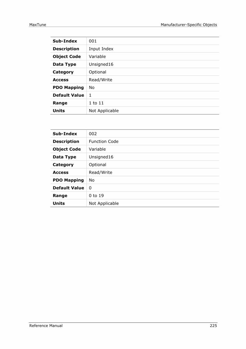
MaxTune Manufacturer-Specific Objects
Reference Manual 225
Sub-Index 001
Description Input Index
Object Code Variable
Data Type Unsigned16
Category Optional
Access Read/Write
PDO Mapping No
Default Value 1
Range 1 to 11
Units Not Applicable
Sub-Index 002
Description Function Code
Object Code Variable
Data Type Unsigned16
Category Optional
Access Read/Write
PDO Mapping No
Default Value 0
Range 0 to 19
Units Not Applicable

Manufacturer-Specific Objects MaxTune
226 Reference Manual
20E1h – Rotary Address Switch
Object Description
Index 20E1
Description The rotary switch position that defines the drive
communication address
Object Code Variable
Data Type Visible_String
Category Optional
VarCom ADDR
Entry Description
Access Read Only
PDO Mapping No
Default Value 0
Range 0
Units Not Applicable
20E2h – Test 7-Segment Display
Object Description
Index 20E2
Description Tests the 7-segment display on drive front panel
Object Code Variable
Data Type Unsigned16
Category Optional
VarCom DISPLAYTEST
Entry Description
Access Read/Write
PDO Mapping No
Default Value 0
Range 0 to 1
Units Not Applicable

MaxTune Manufacturer-Specific Objects
Reference Manual 227
20E3h – Encoder Simulation Mode
Object Description
Index 20E3
Description Defines whether encoder simulation is active.
Object Code Variable
Data Type Unsigned16
Category Optional
VarCom ENCOUTMODE
Entry Description
Access Read/Write
PDO Mapping No
Default Value 0
Range 0 to 1
Units Not Applicable
20E4h – Encoder Simulation Resolution
Object Description
Index 20E4
Description The resolution of the encoder simulation output (in number
of lines).
Object Code Variable
Data Type Integer32
Category Optional
VarCom ENCOUTRES
Entry Description
Access Read/Write
PDO Mapping No
Default Value 2048
Range 10000000 to 10000000
Units number of lines

Manufacturer-Specific Objects MaxTune
228 Reference Manual
20E5h – Encoder Simulation Index Position
Object Description
Index 20E5
Description The index offset value of the encoder simulation output.
Object Code Variable
Data Type Unsigned32
Category Optional
VarCom ENCOUTZPOS
Entry Description
Access Read/Write
PDO Mapping No
Default Value 0
Range 0 to 40000000
Units counts
20E6h – Record Done Indicator
Object Description
Index 20E6
Description Indicates whether the recording is complete and data is
available.
Object Code Variable
Data Type Unsigned8
Category Optional
VarCom RECDONE
Entry Description
Access Read Only
PDO Mapping No
Default Value 0
Range 0 to 1
Units Not Applicable

MaxTune Standard Servo Drive Objects
Reference Manual 229
6 Standard Servo Drive Objects
The following standard device profile objects are implemented in the MaxTune.
For more information, refer to the relevant CAN documentation.
603Fh - Error Code
6040h - Controlword
6041h - Statusword
6060h - Modes of Operation
6061h - Modes of Operation Display
6064h - Position Actual Value
6065h - Following Error Window
606Ch - Velocity Actual Value
606Dh - Velocity Window
606Eh - Velocity Window Time
606Fh - Velocity Threshold
6070h - Velocity Threshold Time
6071h - Target Torque
6073h - Maximum Current
6075h - Motor Rated Current
6077h - Torque Actual Value
6079h - DC Link Circuit Voltage
607Ah - Target Position
607Ch - Home Offset
607Dh - Software Position Limit
607Fh - Max Profile Velocity
6080h - Max Motor Speed
6081h - Profile Velocity
6083h - Profile Acceleration
6084h - Profile Deceleration
6085h - Quick Stop Deceleration
608Fh - Position Encoder Resolution
6091h - Gear Ratio
6092h - Feed Constant
6098h - Homing Mode
6099h - Homing Speeds
609Ah - Homing Acceleration
60B0h – Position Offset
60C2h - Interpolation Time Period
60FDh - Digital Inputs
60FEh - Digital Outputs
60FFh - Target Velocity
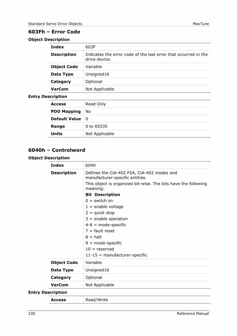
Standard Servo Drive Objects MaxTune
230 Reference Manual
603Fh – Error Code
Object Description
Index 603F
Description Indicates the error code of the last error that occurred in the
drive device.
Object Code Variable
Data Type Unsigned16
Category Optional
VarCom Not Applicable
Entry Description
Access Read Only
PDO Mapping No
Default Value 0
Range 0 to 65535
Units Not Applicable
6040h – Controlword
Object Description
Index 6040
Description Defines the CiA-402 FSA, CiA-402 modes and
manufacturer-specific entities.
This object is organized bit-wise. The bits have the following
meaning:
Bit Description
0 = switch on
1 = enable voltage
2 = quick stop
3 = enable operation
4-6 = mode-specific
7 = fault reset
8 = halt
9 = mode-specific
10 = reserved
11-15 = manufacturer-specific
Object Code Variable
Data Type Unsigned16
Category Optional
VarCom Not Applicable
Entry Description
Access Read/Write
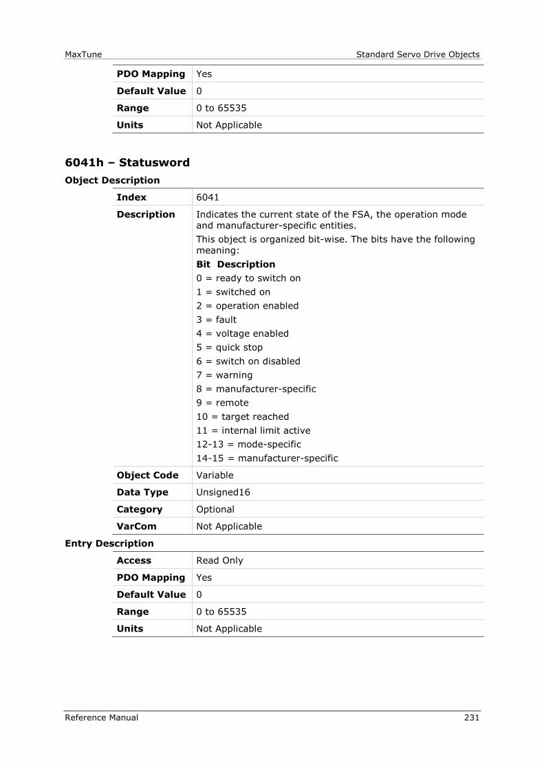
MaxTune Standard Servo Drive Objects
Reference Manual 231
PDO Mapping Yes
Default Value 0
Range 0 to 65535
Units Not Applicable
6041h – Statusword
Object Description
Index 6041
Description Indicates the current state of the FSA, the operation mode
and manufacturer-specific entities.
This object is organized bit-wise. The bits have the following
meaning:
Bit Description
0 = ready to switch on
1 = switched on
2 = operation enabled
3 = fault
4 = voltage enabled
5 = quick stop
6 = switch on disabled
7 = warning
8 = manufacturer-specific
9 = remote
10 = target reached
11 = internal limit active
12-13 = mode-specific
14-15 = manufacturer-specific
Object Code Variable
Data Type Unsigned16
Category Optional
VarCom Not Applicable
Entry Description
Access Read Only
PDO Mapping Yes
Default Value 0
Range 0 to 65535
Units Not Applicable
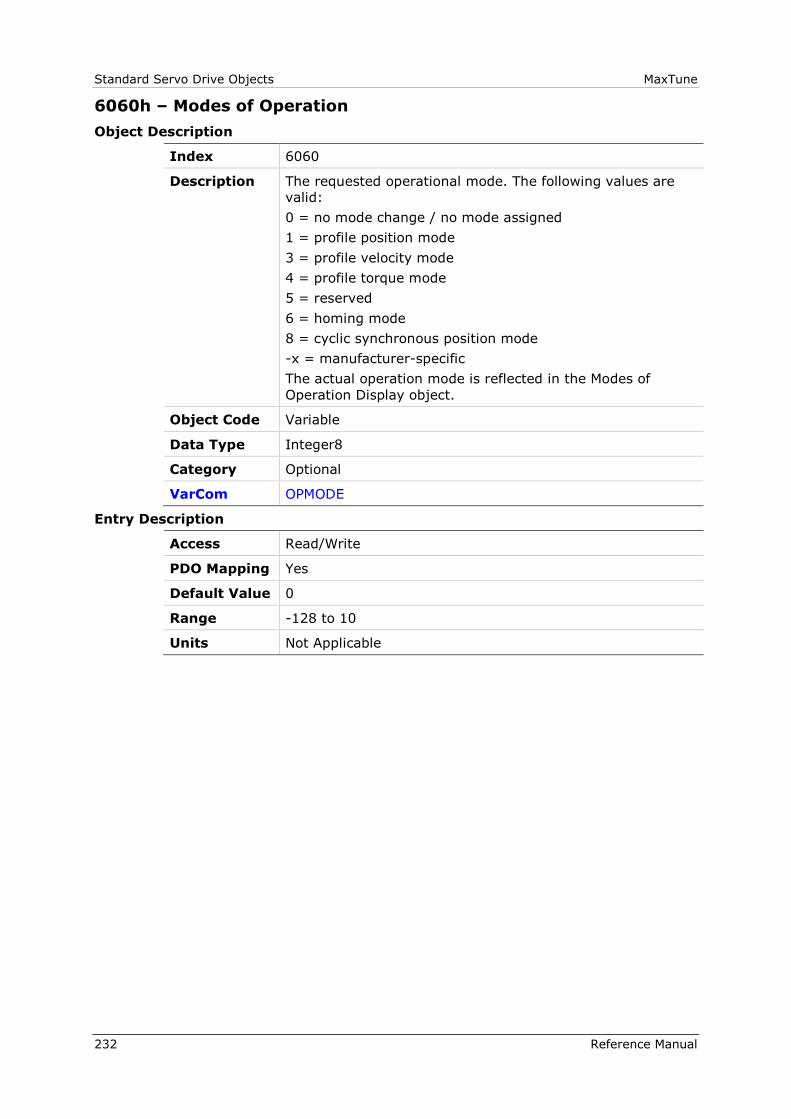
Standard Servo Drive Objects MaxTune
232 Reference Manual
6060h – Modes of Operation
Object Description
Index 6060
Description The requested operational mode. The following values are
valid:
0 = no mode change / no mode assigned
1 = profile position mode
3 = profile velocity mode
4 = profile torque mode
5 = reserved
6 = homing mode
8 = cyclic synchronous position mode
-x = manufacturer-specific
The actual operation mode is reflected in the Modes of
Operation Display object.
Object Code Variable
Data Type Integer8
Category Optional
VarCom OPMODE
Entry Description
Access Read/Write
PDO Mapping Yes
Default Value 0
Range -128 to 10
Units Not Applicable
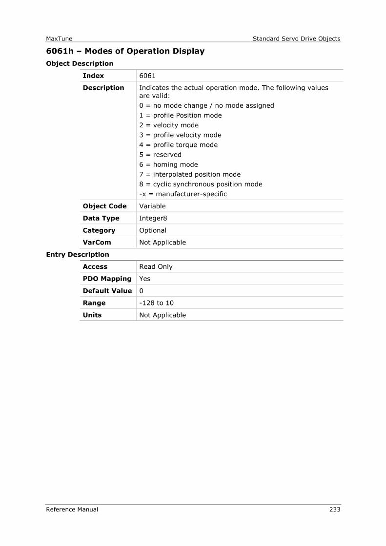
MaxTune Standard Servo Drive Objects
Reference Manual 233
6061h – Modes of Operation Display
Object Description
Index 6061
Description Indicates the actual operation mode. The following values
are valid:
0 = no mode change / no mode assigned
1 = profile Position mode
2 = velocity mode
3 = profile velocity mode
4 = profile torque mode
5 = reserved
6 = homing mode
7 = interpolated position mode
8 = cyclic synchronous position mode
-x = manufacturer-specific
Object Code Variable
Data Type Integer8
Category Optional
VarCom Not Applicable
Entry Description
Access Read Only
PDO Mapping Yes
Default Value 0
Range -128 to 10
Units Not Applicable
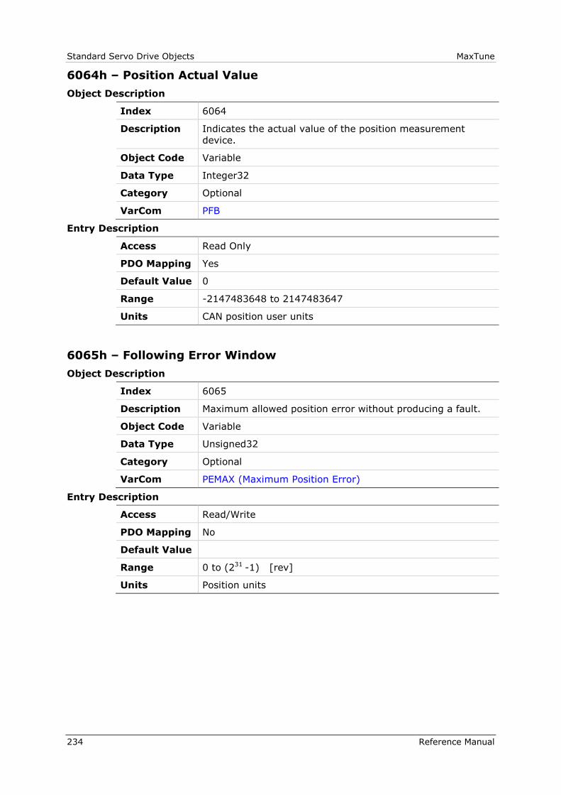
Standard Servo Drive Objects MaxTune
234 Reference Manual
6064h – Position Actual Value
Object Description
Index 6064
Description Indicates the actual value of the position measurement
device.
Object Code Variable
Data Type Integer32
Category Optional
VarCom PFB
Entry Description
Access Read Only
PDO Mapping Yes
Default Value 0
Range -2147483648 to 2147483647
Units CAN position user units
6065h – Following Error Window
Object Description
Index 6065
Description Maximum allowed position error without producing a fault.
Object Code Variable
Data Type Unsigned32
Category Optional
VarCom PEMAX (Maximum Position Error)
Entry Description
Access Read/Write
PDO Mapping No
Default Value
Range 0 to (231 -1) [rev]
Units Position units
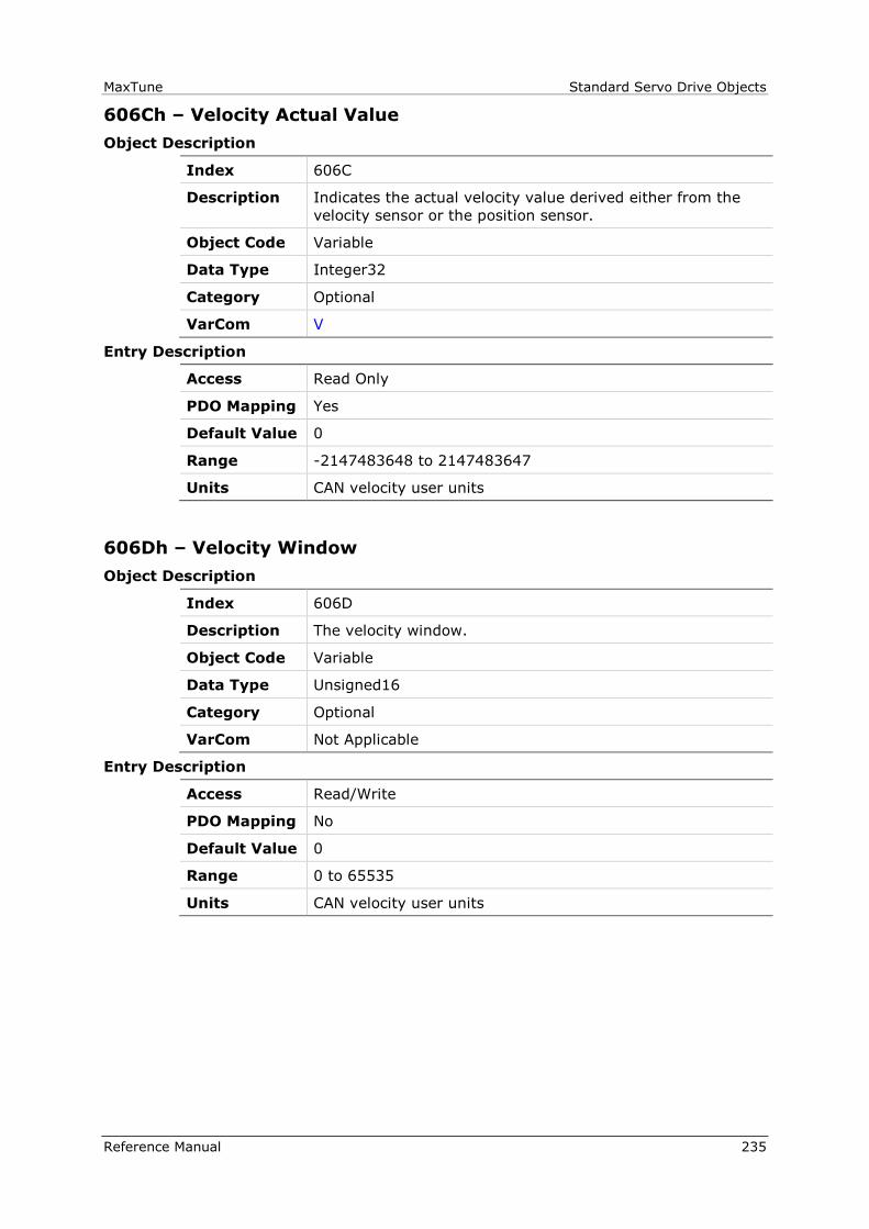
MaxTune Standard Servo Drive Objects
Reference Manual 235
606Ch – Velocity Actual Value
Object Description
Index 606C
Description Indicates the actual velocity value derived either from the
velocity sensor or the position sensor.
Object Code Variable
Data Type Integer32
Category Optional
VarCom V
Entry Description
Access Read Only
PDO Mapping Yes
Default Value 0
Range -2147483648 to 2147483647
Units CAN velocity user units
606Dh – Velocity Window
Object Description
Index 606D
Description The velocity window.
Object Code Variable
Data Type Unsigned16
Category Optional
VarCom Not Applicable
Entry Description
Access Read/Write
PDO Mapping No
Default Value 0
Range 0 to 65535
Units CAN velocity user units

Standard Servo Drive Objects MaxTune
236 Reference Manual
606Eh – Velocity Window Time
Object Description
Index 606E
Description The velocity window time.
Object Code Variable
Data Type Unsigned16
Category Optional
VarCom Not Applicable
Entry Description
Access Read/Write
PDO Mapping No
Default Value 0
Range 0 to 65535
Units milliseconds (ms)
606Fh – Velocity Threshold
Object Description
Index 606F
Description The velocity threshold.
Object Code Variable
Data Type Unsigned16
Category Optional
VarCom Not Applicable
Entry Description
Access Read/Write
PDO Mapping No
Default Value 0
Range 0 to 65535
Units CAN velocity user units
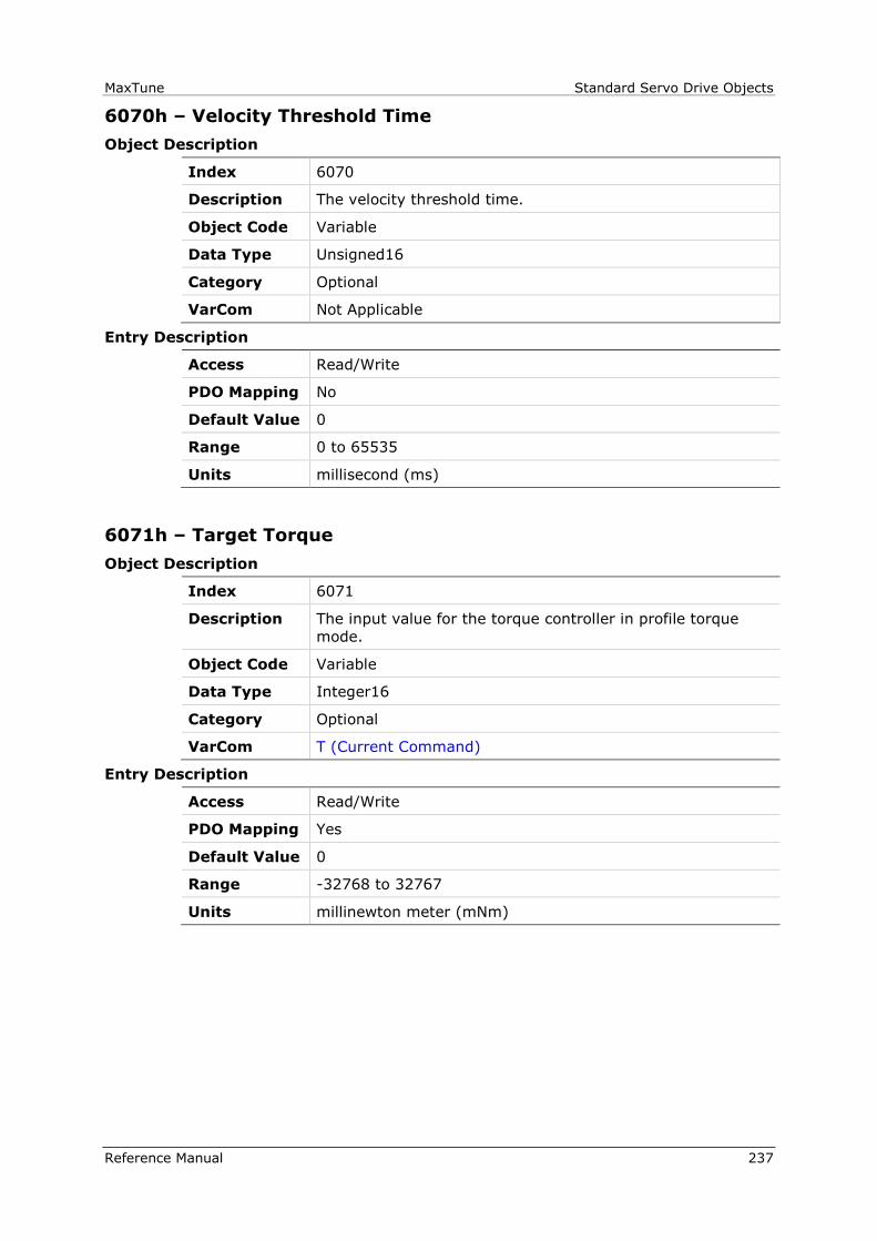
MaxTune Standard Servo Drive Objects
Reference Manual 237
6070h – Velocity Threshold Time
Object Description
Index 6070
Description The velocity threshold time.
Object Code Variable
Data Type Unsigned16
Category Optional
VarCom Not Applicable
Entry Description
Access Read/Write
PDO Mapping No
Default Value 0
Range 0 to 65535
Units millisecond (ms)
6071h – Target Torque
Object Description
Index 6071
Description The input value for the torque controller in profile torque
mode.
Object Code Variable
Data Type Integer16
Category Optional
VarCom T (Current Command)
Entry Description
Access Read/Write
PDO Mapping Yes
Default Value 0
Range -32768 to 32767
Units millinewton meter (mNm)

Standard Servo Drive Objects MaxTune
238 Reference Manual
6073h – Maximum Current
Object Description
Index 6073
Description The configured maximum permissible torque creating current
in the motor.
Object Code Variable
Data Type Unsigned16
Category Optional
VarCom IMAX
Entry Description
Access Read/Write
PDO Mapping No
Default Value 0
Range 0 to 65535
Units milliampere (mA)
6075h – Motor Rated Current
Object Description
Index 6075
Description The motor rated current. It is taken from the motor
nameplate. Depending on the motor and drive technology
this current is DC, peak or rms (root-mean-square) current.
All relative current data refers to this value.
Object Code Variable
Data Type Unsigned32
Category Optional
VarCom MICONT
Entry Description
Access Read/Write
PDO Mapping No
Default Value 0
Range 0 to 4294967295
Units mA
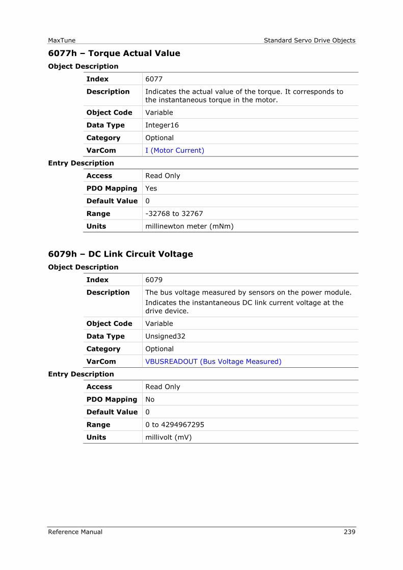
MaxTune Standard Servo Drive Objects
Reference Manual 239
6077h – Torque Actual Value
Object Description
Index 6077
Description Indicates the actual value of the torque. It corresponds to
the instantaneous torque in the motor.
Object Code Variable
Data Type Integer16
Category Optional
VarCom I (Motor Current)
Entry Description
Access Read Only
PDO Mapping Yes
Default Value 0
Range -32768 to 32767
Units millinewton meter (mNm)
6079h – DC Link Circuit Voltage
Object Description
Index 6079
Description The bus voltage measured by sensors on the power module.
Indicates the instantaneous DC link current voltage at the
drive device.
Object Code Variable
Data Type Unsigned32
Category Optional
VarCom VBUSREADOUT (Bus Voltage Measured)
Entry Description
Access Read Only
PDO Mapping No
Default Value 0
Range 0 to 4294967295
Units millivolt (mV)
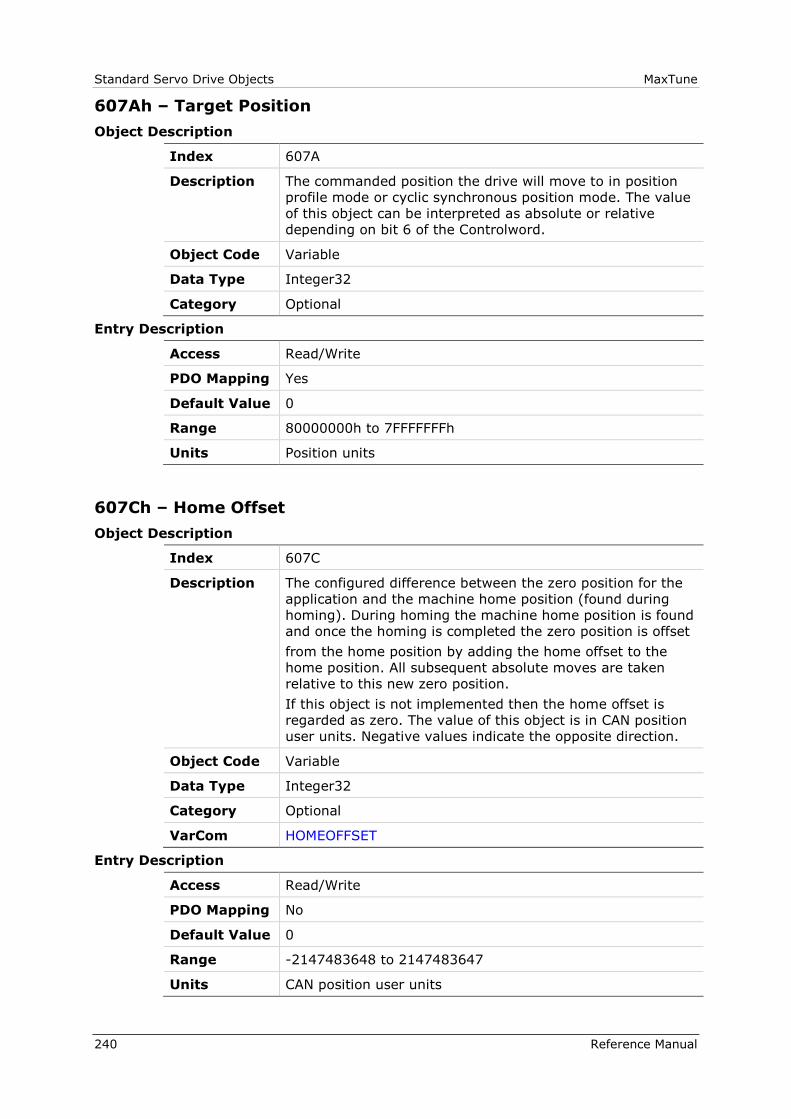
Standard Servo Drive Objects MaxTune
240 Reference Manual
607Ah – Target Position
Object Description
Index 607A
Description The commanded position the drive will move to in position
profile mode or cyclic synchronous position mode. The value
of this object can be interpreted as absolute or relative
depending on bit 6 of the Controlword.
Object Code Variable
Data Type Integer32
Category Optional
Entry Description
Access Read/Write
PDO Mapping Yes
Default Value 0
Range 80000000h to 7FFFFFFFh
Units Position units
607Ch – Home Offset
Object Description
Index 607C
Description The configured difference between the zero position for the
application and the machine home position (found during
homing). During homing the machine home position is found
and once the homing is completed the zero position is offset
from the home position by adding the home offset to the
home position. All subsequent absolute moves are taken
relative to this new zero position.
If this object is not implemented then the home offset is
regarded as zero. The value of this object is in CAN position
user units. Negative values indicate the opposite direction.
Object Code Variable
Data Type Integer32
Category Optional
VarCom HOMEOFFSET
Entry Description
Access Read/Write
PDO Mapping No
Default Value 0
Range -2147483648 to 2147483647
Units CAN position user units
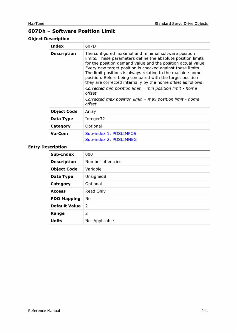
MaxTune Standard Servo Drive Objects
Reference Manual 241
607Dh – Software Position Limit
Object Description
Index 607D
Description The configured maximal and minimal software position
limits. These parameters define the absolute position limits
for the position demand value and the position actual value.
Every new target position is checked against these limits.
The limit positions is always relative to the machine home
position. Before being compared with the target position
they are corrected internally by the home offset as follows:
Corrected min position limit = min position limit - home
offset
Corrected max position limit = max position limit - home
offset
Object Code Array
Data Type Integer32
Category Optional
VarCom Sub-index 1: POSLIMPOS
Sub-index 2: POSLIMNEG
Entry Description
Sub-Index 000
Description Number of entries
Object Code Variable
Data Type Unsigned8
Category Optional
Access Read Only
PDO Mapping No
Default Value 2
Range 2
Units Not Applicable

Standard Servo Drive Objects MaxTune
242 Reference Manual
Sub-Index 001
Description Minimum software position limit
Object Code Variable
Data Type Integer32
Category Optional
Access Read/Write
PDO Mapping No
Default Value 0
Range -2147483648 to 2147483647
Units CAN position user units
Sub-Index 002
Description Maximum software position limit
Object Code Variable
Data Type Integer32
Category Optional
Access Read/Write
PDO Mapping No
Default Value 0
Range -2147483648 to 2147483647
Units CAN position user units
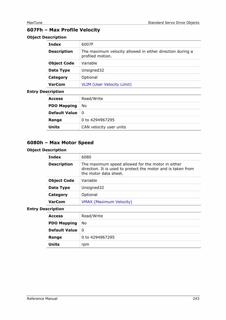
MaxTune Standard Servo Drive Objects
Reference Manual 243
607Fh – Max Profile Velocity
Object Description
Index 6007F
Description The maximum velocity allowed in either direction during a
profiled motion.
Object Code Variable
Data Type Unsigned32
Category Optional
VarCom VLIM (User Velocity Limit)
Entry Description
Access Read/Write
PDO Mapping No
Default Value 0
Range 0 to 4294967295
Units CAN velocity user units
6080h – Max Motor Speed
Object Description
Index 6080
Description The maximum speed allowed for the motor in either
direction. It is used to protect the motor and is taken from
the motor data sheet.
Object Code Variable
Data Type Unsigned32
Category Optional
VarCom VMAX (Maximum Velocity)
Entry Description
Access Read/Write
PDO Mapping No
Default Value 0
Range 0 to 4294967295
Units rpm
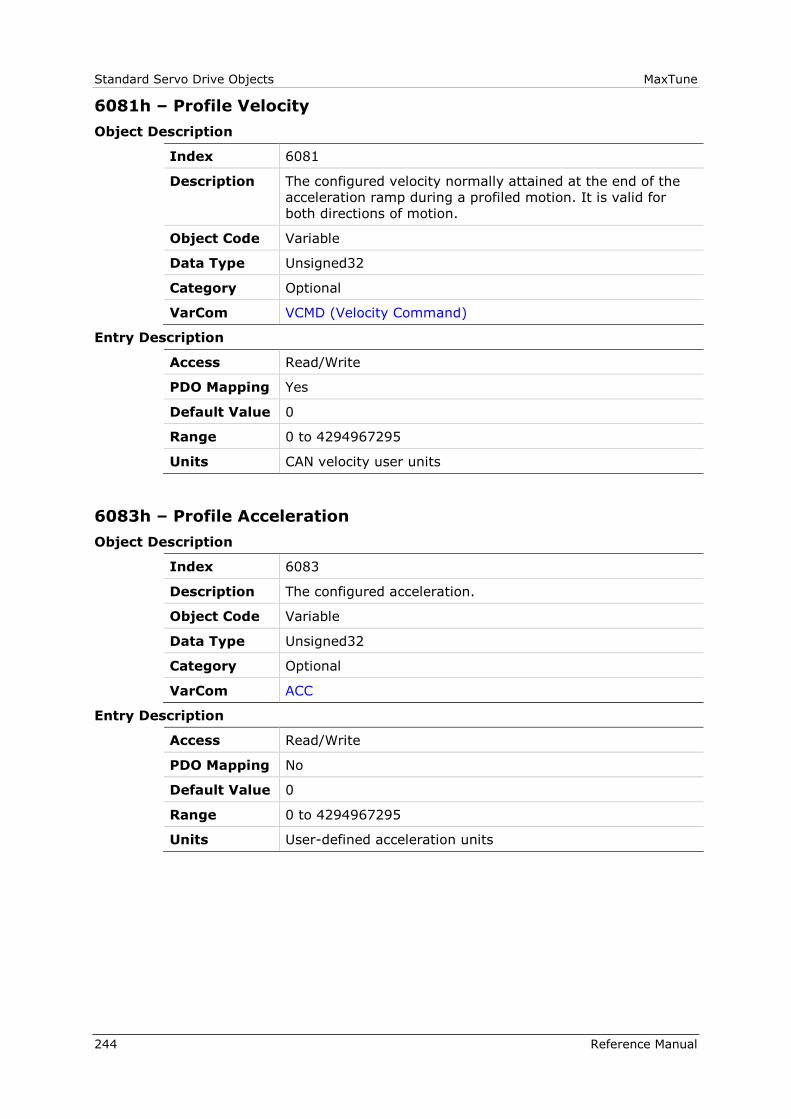
Standard Servo Drive Objects MaxTune
244 Reference Manual
6081h – Profile Velocity
Object Description
Index 6081
Description The configured velocity normally attained at the end of the
acceleration ramp during a profiled motion. It is valid for
both directions of motion.
Object Code Variable
Data Type Unsigned32
Category Optional
VarCom VCMD (Velocity Command)
Entry Description
Access Read/Write
PDO Mapping Yes
Default Value 0
Range 0 to 4294967295
Units CAN velocity user units
6083h – Profile Acceleration
Object Description
Index 6083
Description The configured acceleration.
Object Code Variable
Data Type Unsigned32
Category Optional
VarCom ACC
Entry Description
Access Read/Write
PDO Mapping No
Default Value 0
Range 0 to 4294967295
Units User-defined acceleration units
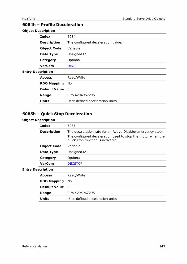
MaxTune Standard Servo Drive Objects
Reference Manual 245
6084h – Profile Deceleration
Object Description
Index 6084
Description The configured deceleration value.
Object Code Variable
Data Type Unsigned32
Category Optional
VarCom DEC
Entry Description
Access Read/Write
PDO Mapping No
Default Value 0
Range 0 to 4294967295
Units User-defined acceleration units
6085h – Quick Stop Deceleration
Object Description
Index 6085
Description The deceleration rate for an Active Disable/emergency stop.
The configured deceleration used to stop the motor when the
quick stop function is activated.
Object Code Variable
Data Type Unsigned32
Category Optional
VarCom DECSTOP
Entry Description
Access Read/Write
PDO Mapping No
Default Value 0
Range 0 to 4294967295
Units User-defined acceleration units

Standard Servo Drive Objects MaxTune
246 Reference Manual
608Fh – Position Encoder Resolution
Object Description
Index 608F
Description The resolution of the motor encoder in number of lines per
revolution of the motor.
The position encoder resolution is calculated by the
following:
position encoder resolution = encoder increments ÷
motor revolutions
Object Code Array
Data Type Unsigned32
Category Optional
VarCom MENCRES
Entry Description
Sub-Index 000
Description Number of entries
Object Code Variable
Data Type Unsigned8
Category Optional
Access Read Only
PDO Mapping No
Default Value 2
Range 2
Units Not Applicable
Sub-Index 001
Description Encoder increments
Object Code Unsigned32
Data Type Variable
Category Optional
Access Read/Write
PDO Mapping No
Default Value 2048
Range 1 to 10000000
Units Not Applicable
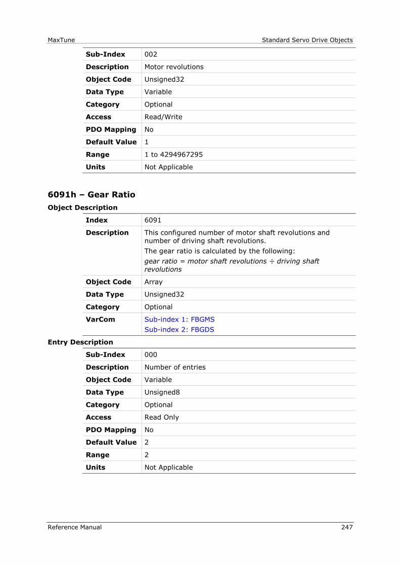
MaxTune Standard Servo Drive Objects
Reference Manual 247
Sub-Index 002
Description Motor revolutions
Object Code Unsigned32
Data Type Variable
Category Optional
Access Read/Write
PDO Mapping No
Default Value 1
Range 1 to 4294967295
Units Not Applicable
6091h – Gear Ratio
Object Description
Index 6091
Description This configured number of motor shaft revolutions and
number of driving shaft revolutions.
The gear ratio is calculated by the following:
gear ratio = motor shaft revolutions ÷ driving shaft
revolutions
Object Code Array
Data Type Unsigned32
Category Optional
VarCom Sub-index 1: FBGMS
Sub-index 2: FBGDS
Entry Description
Sub-Index 000
Description Number of entries
Object Code Variable
Data Type Unsigned8
Category Optional
Access Read Only
PDO Mapping No
Default Value 2
Range 2
Units Not Applicable

Standard Servo Drive Objects MaxTune
248 Reference Manual
Sub-Index 001
Description Motor revolutions
Object Code Variable
Data Type Unsigned32
Category Optional
Access Read/Write
PDO Mapping No
Default Value 1
Range 1 to 4294967295
Units Not Applicable
Sub-Index 002
Description Shaft revolutions
Object Code Variable
Data Type Unsigned32
Category Optional
Access Read/Write
PDO Mapping No
Default Value 1
Range 1 to 4294967295
Units Not Applicable
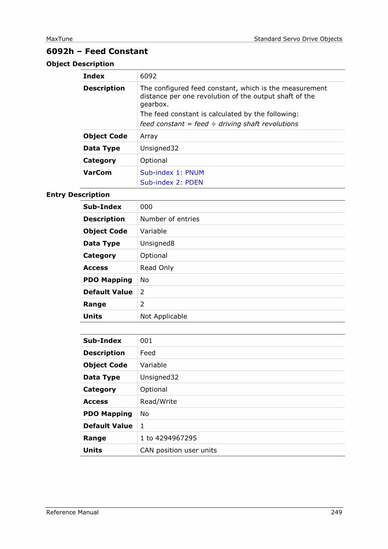
MaxTune Standard Servo Drive Objects
Reference Manual 249
6092h – Feed Constant
Object Description
Index 6092
Description The configured feed constant, which is the measurement
distance per one revolution of the output shaft of the
gearbox.
The feed constant is calculated by the following:
feed constant = feed ÷ driving shaft revolutions
Object Code Array
Data Type Unsigned32
Category Optional
VarCom Sub-index 1: PNUM
Sub-index 2: PDEN
Entry Description
Sub-Index 000
Description Number of entries
Object Code Variable
Data Type Unsigned8
Category Optional
Access Read Only
PDO Mapping No
Default Value 2
Range 2
Units Not Applicable
Sub-Index 001
Description Feed
Object Code Variable
Data Type Unsigned32
Category Optional
Access Read/Write
PDO Mapping No
Default Value 1
Range 1 to 4294967295
Units CAN position user units
Standard Servo Drive Objects MaxTune
250 Reference Manual
Sub-Index 002
Description Shaft revolutions
Object Code Variable
Data Type Unsigned32
Category Optional
Access Read/Write
PDO Mapping No
Default Value 1
Range 1 to 4294967295
Units Not Applicable
6098h – Homing Mode
Object Description
Index 6098
Description The homing method to be used.
The following value definition is valid:
0 = no homing method assigned
1 = homing method 1 to be used
.
.
36 = homing method 36 to be used
-x = manufacturer-specific
Refer to the CiA-402 standard for the detailed description of
each homing method.
Object Code Variable
Data Type Integer8
Category Optional
VarCom HOMETYPE
Entry Description
Access Read/Write
PDO Mapping No
Default Value 1
Range -64 to 36
Units Not Applicable

MaxTune Standard Servo Drive Objects
Reference Manual 251
6099h – Homing Speeds
Object Description
Index 6099
Description The commanded speeds used during homing procedure.
Object Code Array
Data Type Unsigned32
Category Optional
VarCom Sub-index 1: HOMESPEED1
Sub-index 2: HOMESPEED2
Entry Description
Sub-Index 000
Description Number of entries
Object Code Variable
Data Type Unsigned8
Category Optional
Access Read Only
PDO Mapping No
Default Value 2
Range 2
Units Not Applicable
Sub-Index 001
Description Fast homing speed. Switch search.
Object Code Variable
Data Type Unsigned32
Category Optional
Access Read/Write
PDO Mapping No
Default Value 0
Range 0 to 4294967295
Units CAN velocity user units
Standard Servo Drive Objects MaxTune
252 Reference Manual
Sub-Index 002
Description Slow homing speed. Index search.
Object Code Variable
Data Type Unsigned32
Category Optional
Access Read/Write
PDO Mapping No
Default Value 0
Range 0 to 4294967295
Units CAN velocity user units
609Ah – Homing Acceleration
Object Description
Index 609A
Description The acceleration and deceleration to be used during homing
operation.
Object Code Variable
Data Type Unsigned32
Category Optional
VarCom HOMEACC
Entry Description
Access Read/Write
PDO Mapping No
Default Value 0
Range 0 to 4294967295
Units User-defined acceleration units

MaxTune Standard Servo Drive Objects
Reference Manual 253
60B0h – Position Offset
Object Description
Index 60B0
Description The offset of the target position.
Object Code Variable
Data Type Integer32
Category Optional
VarCom PFBOFFSET
Entry Description
Access Read/Write
PDO Mapping No
Default Value 0
Range ±(231 - 1) [rev]
Units Position units

Standard Servo Drive Objects MaxTune
254 Reference Manual
60C2h – Interpolation Time Period
Object Description
Index 60C2
Description The configured interpolation cycle time.
This object includes the following sub-indices:
sub-index 1: value of the time
sub-index 2: dimension index of the time value in
sub-index 1
Object Code Record
Data Type Interpolation time period record (0080)
Category Optional
VarCom Sub-index 1: FBITPRD
Sub-index 2: FBITIDX
Entry Description
Sub-Index 000
Description Number of entries
Object Code Variable
Data Type Unsigned8
Category Optional
Access Read Only
PDO Mapping No
Default Value 2
Range 2
Units Not Applicable
Sub-Index 001
Description Interpolation time period value.
Object Code Variable
Data Type Unsigned8
Category Optional
Access Read/Write
PDO Mapping No
Default Value 1
Range 1 to 255
Units 10(interpolation time index) s(econd)
MaxTune Standard Servo Drive Objects
Reference Manual 255
Sub-Index 002
Description Interpolation time index
Object Code Variable
Data Type Integer8
Category Optional
Access Read/Write
PDO Mapping No
Default Value -3
Range -128 to 63
Units Not Applicable
60FDh – Digital Inputs
Object Description
Index 60FD
Description Indicates the state of the digital inputs.
This object is organized bit-wise. The bits have the following
meaning:
0 = negative limit switch
1 = positive limit switch
2 = home switch
3 = interlock
16-31 = manufacturer-specific
The bit values have the following meaning:
0 = switch is off
1 = switch is on
Object Code Variable
Data Type Unsigned32
Category Optional
VarCom IN
Entry Description
Access Read Only
PDO Mapping Yes
Default Value 0
Range 0 to 4294967295
Units Not Applicable
Standard Servo Drive Objects MaxTune
256 Reference Manual
60FEh – Digital Outputs
Object Description
Index 60Fr
Description Indicates the state of the digital outputs.
This object is organized bit-wise. The bits have the following
meaning:
0 = set brake
16-31 = manufacturer-specific
This object includes the following sub-indices:
Sub-index 1: for the physical output value
Sub-index 2: mask for the physical outputs
The bit values for sub-index 1 have the following meaning:
0 = output is off, brake is not set
1 = output is on, brake is set
The bit values for sub-index 2 have the following meaning:
0 = disable output; output will not change
1 = enable output; output will not change
Object Code Unsigned32
Data Type Array
Category Optional
VarCom OUT
Entry Description
Sub-Index 000
Description Number of entries
Object Code Variable
Data Type Unsigned8
Category Optional
Access Read Only
PDO Mapping No
Default Value 2
Range 2
Units Not Applicable

MaxTune Standard Servo Drive Objects
Reference Manual 257
Sub-Index 001
Description Physical outputs
Object Code Variable
Data Type Unsigned32
Category Optional
Access Read/Write
PDO Mapping Yes
Default Value 0
Range 0 to 4294967295
Units Not Applicable
Sub-Index 002
Description Output mask
Object Code Variable
Data Type Unsigned32
Category Optional
Access Read/Write
PDO Mapping Yes
Default Value 0
Range 0 to 4294967295
Units Not Applicable

Standard Servo Drive Objects MaxTune
258 Reference Manual
60FFh – Target Velocity
Object Description
Index 60FF
Description The configured target velocity and is used as input for the
trajectory generator.
Object Code Variable
Data Type Integer32
Category Optional
VarCom Not Applicable
Entry Description
Access Read/Write
PDO Mapping Yes
Default Value 0
Range -2147483648 to 2147483647
Units CAN velocity user units
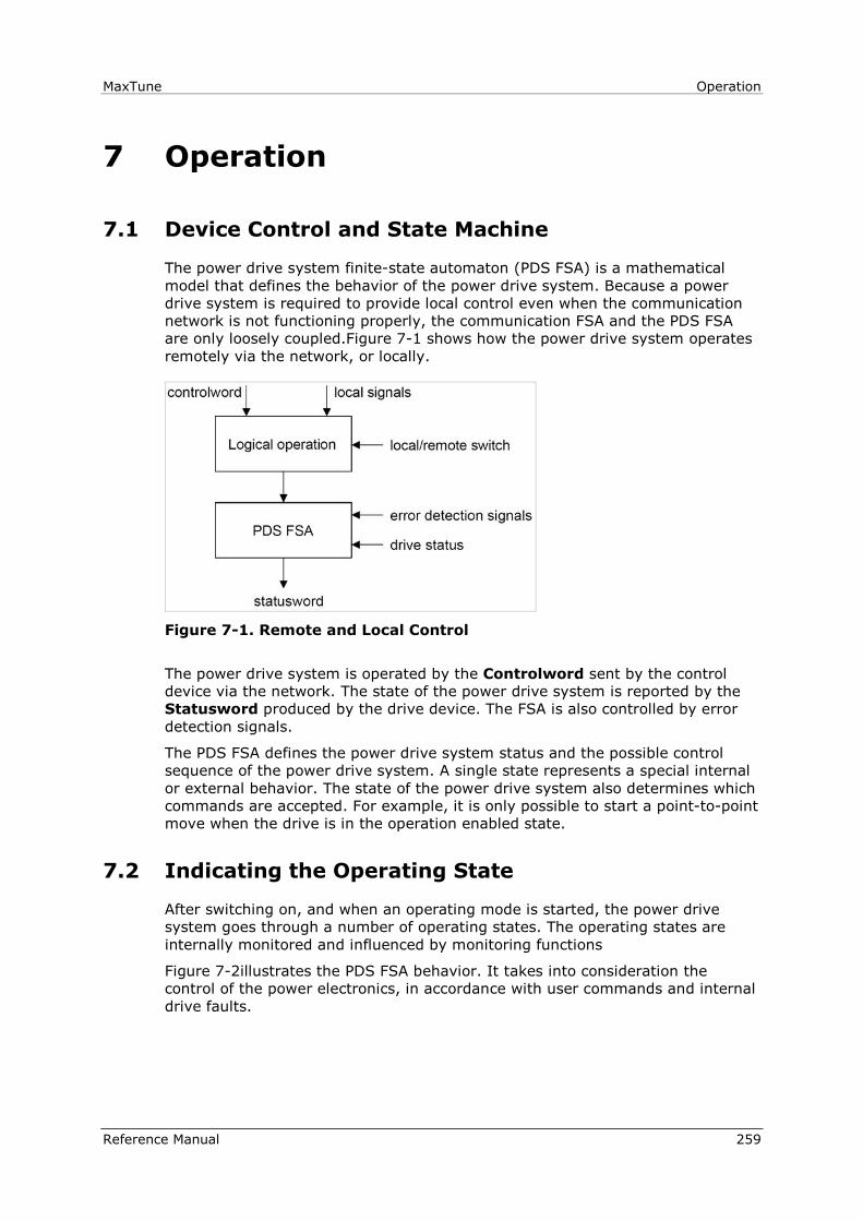
MaxTune Operation
Reference Manual 259
7 Operation
7.1 Device Control and State Machine
The power drive system finite-state automaton (PDS FSA) is a mathematical
model that defines the behavior of the power drive system. Because a power
drive system is required to provide local control even when the communication
network is not functioning properly, the communication FSA and the PDS FSA
are only loosely coupled.Figure 7-1 shows how the power drive system operates
remotely via the network, or locally.
Figure 7-1. Remote and Local Control
The power drive system is operated by the Controlword sent by the control
device via the network. The state of the power drive system is reported by the
Statusword produced by the drive device. The FSA is also controlled by error
detection signals.
The PDS FSA defines the power drive system status and the possible control
sequence of the power drive system. A single state represents a special internal
or external behavior. The state of the power drive system also determines which
commands are accepted. For example, it is only possible to start a point-to-point
move when the drive is in the operation enabled state.
7.2 Indicating the Operating State
After switching on, and when an operating mode is started, the power drive
system goes through a number of operating states. The operating states are
internally monitored and influenced by monitoring functions
Figure 7-2illustrates the PDS FSA behavior. It takes into consideration the
control of the power electronics, in accordance with user commands and internal
drive faults.

Operation MaxTune
260 Reference Manual
Figure 7-2. Power Drive System State Diagram
Notes:
Not Ready to Switch On “Not ready to operate” received from the controller.
Switch On Disabled Ready to operate. Can read and write parameters.
Motion functionality cannot be executed.
Ready to Switch On Ready to operate. Can read and write parameters.
Motion functionality cannot be executed. Bus
voltage must be switched on.
Operation Enabled Drive power stage is enabled. No fault is present.
Motion functionality can be executed.
Quick Stop Active Drive was stopped using controlled stop. Power
stage is enabled. Motion functionality cannot be
executed.
Fault Reaction Active A fault has occurred. Drive is in the process of
ramping down to 0 velocity (Active Disable process).
Fault A fault has occurred. Power stage is disabled.
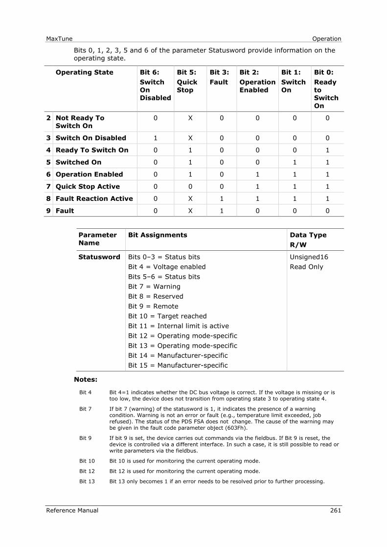
MaxTune Operation
Reference Manual 261
Bits 0, 1, 2, 3, 5 and 6 of the parameter Statusword provide information on the
operating state.
Operating State Bit 6:
Switch
On
Disabled
Bit 5:
Quick
Stop
Bit 3:
Fault
Bit 2:
Operation
Enabled
Bit 1:
Switch
On
Bit 0:
Ready
to
Switch
On
2 Not Ready To
Switch On
0 X 0 0 0 0
3 Switch On Disabled 1 X 0 0 0 0
4 Ready To Switch On 0 1 0 0 0 1
5 Switched On 0 1 0 0 1 1
6 Operation Enabled 0 1 0 1 1 1
7 Quick Stop Active 0 0 0 1 1 1
8 Fault Reaction Active 0 X 1 1 1 1
9 Fault 0 X 1 0 0 0
Parameter
Name
Bit Assignments Data Type
R/W
Statusword Bits 0–3 = Status bits
Bit 4 = Voltage enabled
Bits 5–6 = Status bits
Bit 7 = Warning
Bit 8 = Reserved
Bit 9 = Remote
Bit 10 = Target reached
Bit 11 = Internal limit is active
Bit 12 = Operating mode-specific
Bit 13 = Operating mode-specific
Bit 14 = Manufacturer-specific
Bit 15 = Manufacturer-specific
Unsigned16
Read Only
Notes:
Bit 4 Bit 4=1 indicates whether the DC bus voltage is correct. If the voltage is missing or is too low, the device does not transition from operating state 3 to operating state 4.
Bit 7 If bit 7 (warning) of the statusword is 1, it indicates the presence of a warning condition. Warning is not an error or fault (e.g., temperature limit exceeded, job refused). The status of the PDS FSA does not change. The cause of the warning may be given in the fault code parameter object (603Fh).
Bit 9 If bit 9 is set, the device carries out commands via the fieldbus. If Bit 9 is reset, the device is controlled via a different interface. In such a case, it is still possible to read or write parameters via the fieldbus.
Bit 10 Bit 10 is used for monitoring the current operating mode.
Bit 12 Bit 12 is used for monitoring the current operating mode.
Bit 13 Bit 13 only becomes 1 if an error needs to be resolved prior to further processing.
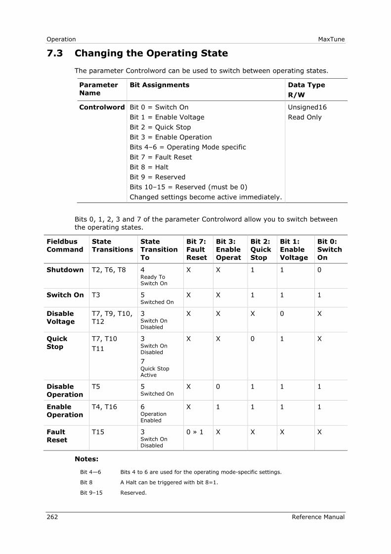
Operation MaxTune
262 Reference Manual
7.3 Changing the Operating State
The parameter Controlword can be used to switch between operating states.
Parameter
Name
Bit Assignments Data Type
R/W
Controlword Bit 0 = Switch On
Bit 1 = Enable Voltage
Bit 2 = Quick Stop
Bit 3 = Enable Operation
Bits 4–6 = Operating Mode specific
Bit 7 = Fault Reset
Bit 8 = Halt
Bit 9 = Reserved
Bits 10–15 = Reserved (must be 0)
Changed settings become active immediately.
Unsigned16
Read Only
Bits 0, 1, 2, 3 and 7 of the parameter Controlword allow you to switch between
the operating states.
Fieldbus
Command
State
Transitions
State
Transition
To
Bit 7:
Fault
Reset
Bit 3:
Enable
Operat
Bit 2:
Quick
Stop
Bit 1:
Enable
Voltage
Bit 0:
Switch
On
Shutdown T2, T6, T8 4 Ready To Switch On
X X 1 1 0
Switch On T3 5 Switched On
X X 1 1 1
Disable
Voltage
T7, T9, T10,
T12
3 Switch On Disabled
X X X 0 X
Quick
Stop
T7, T10
T11
3 Switch On Disabled
7 Quick Stop Active
X X 0 1 X
Disable
Operation
T5 5 Switched On
X 0 1 1 1
Enable
Operation
T4, T16 6 Operation Enabled
X 1 1 1 1
Fault
Reset
T15 3 Switch On Disabled
0 » 1 X X X X
Notes:
Bit 4—6 Bits 4 to 6 are used for the operating mode-specific settings.
Bit 8 A Halt can be triggered with bit 8=1.
Bit 9–15 Reserved.

MaxTune Operation
Reference Manual 263
7.4 Starting and Changing an Operating Mode
The parameter Mode of operation (6060h) is used to set the desired operating
mode.
Parameter
Name
Description Data
Type R/W
Mode of
operation
Operating mode
1 Profile Position
3 Profile Velocity
4 Profile Torque
6 Homing
7 Interpolated Position*
8 Cyclic Synchronous Position
9 Cyclic Synchronous Position
10 Cyclic Synchronous Position
Changed settings become active immediately.
Integer8
Read/Write
* Note: Not supported
The parameter Mode of operation display (6061h) can be used to read the
current operating mode.
Parameter
Name
Description Data
Type R/W
Mode of
operation
Operating mode
1 Profile Position
3 Profile Velocity
4 Profile Torque
6 Homing
7 Interpolated Position*
8 Cyclic Synchronous Position
9 Cyclic Synchronous Position
10 Cyclic Synchronous Position
Changed settings become active immediately.
Integer8
Read/Write
* Note: Not supported
Operation MaxTune
264 Reference Manual
7.5 Operating Mode Profile Position
Description
In the operating mode Profile Position, a movement to a desired target position
is performed.
Procedure
Set [Mode of operation (6060h)] to operating mode Profile position (1).
Set [Target position (607Ah)] to the target position (unit = pulse).
Set [Profile velocity (6081h)] to profile velocity (unit = pulses per second).
Set [Controlword (6040h)] to start the movement.
Query [Position actual value (6064h)] to get the actual position of the
motor.
Query [Statusword (6041h)] to get the current status of following error, set-
point acknowledge and target reached.
Optional
Additional information on the operating mode Profile Position:
Query [Position demand value (6062h)] to get the internal reference value
(unit = pulse).
Query [Position actual value (6063h)] to get the actual position value
(unit = increments).
Following error:
Set [Following error window (6065h)] to the permissible following error
(unit = pulse).
Query [Following error actual value (60F4h)] to get the current following
error (unit = pulse).
Standstill window:
Set [Position window (6067h)] to the value for the standstill window. If the
difference between the target position and the current motor position
remains in the standstill window for the time Position window time (6065h),
the target position is considered to have been reached (unit = pulse).
Set [Position window time (6068h)] to the value for the standstill window. If
the difference between the target position and the current motor position
remains in the standstill window for the time Position window time (6065h),
the target position is considered to have been reached (unit = pulse).
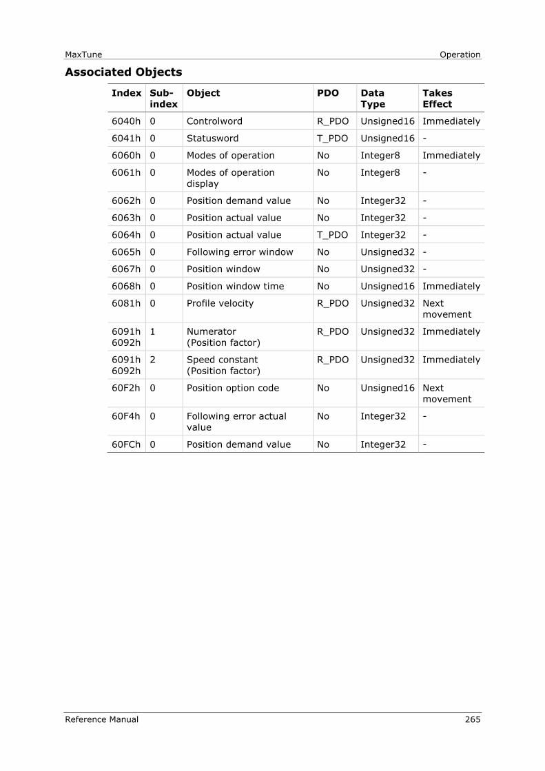
MaxTune Operation
Reference Manual 265
Associated Objects
Index Sub-
index
Object PDO Data
Type
Takes
Effect
6040h 0 Controlword R_PDO Unsigned16 Immediately
6041h 0 Statusword T_PDO Unsigned16 -
6060h 0 Modes of operation No Integer8 Immediately
6061h 0 Modes of operation
display
No Integer8 -
6062h 0 Position demand value No Integer32 -
6063h 0 Position actual value No Integer32 -
6064h 0 Position actual value T_PDO Integer32 -
6065h 0 Following error window No Unsigned32 -
6067h 0 Position window No Unsigned32 -
6068h 0 Position window time No Unsigned16 Immediately
6081h 0 Profile velocity R_PDO Unsigned32 Next
movement
6091h
6092h
1 Numerator
(Position factor)
R_PDO Unsigned32 Immediately
6091h
6092h
2 Speed constant
(Position factor)
R_PDO Unsigned32 Immediately
60F2h 0 Position option code No Unsigned16 Next
movement
60F4h 0 Following error actual
value
No Integer32 -
60FCh 0 Position demand value No Integer32 -
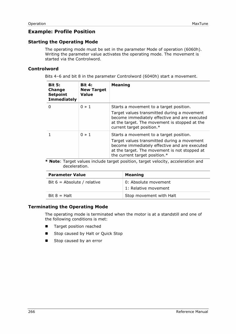
Operation MaxTune
266 Reference Manual
Example: Profile Position
Starting the Operating Mode
The operating mode must be set in the parameter Mode of operation (6060h).
Writing the parameter value activates the operating mode. The movement is
started via the Controlword.
Controlword
Bits 4–6 and bit 8 in the parameter Controlword (6040h) start a movement.
Bit 5:
Change
Setpoint
Immediately
Bit 4:
New Target
Value
Meaning
0 0 » 1 Starts a movement to a target position.
Target values transmitted during a movement
become immediately effective and are executed
at the target. The movement is stopped at the
current target position.*
1 0 » 1 Starts a movement to a target position.
Target values transmitted during a movement
become immediately effective and are executed
at the target. The movement is not stopped at
the current target position.*
* Note: Target values include target position, target velocity, acceleration and
deceleration.
Parameter Value Meaning
Bit 6 = Absolute / relative 0: Absolute movement
1: Relative movement
Bit 8 = Halt Stop movement with Halt
Terminating the Operating Mode
The operating mode is terminated when the motor is at a standstill and one of
the following conditions is met:
Target position reached
Stop caused by Halt or Quick Stop
Stop caused by an error
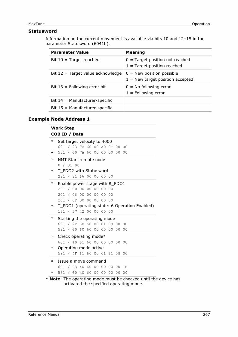
MaxTune Operation
Reference Manual 267
Statusword
Information on the current movement is available via bits 10 and 12–15 in the
parameter Statusword (6041h).
Parameter Value Meaning
Bit 10 = Target reached 0 = Target position not reached
1 = Target position reached
Bit 12 = Target value acknowledge 0 = New position possible
1 = New target position accepted
Bit 13 = Following error bit 0 = No following error
1 = Following error
Bit 14 = Manufacturer-specific
Bit 15 = Manufacturer-specific
Example Node Address 1
Work Step
COB ID / Data
» Set target velocity to 4000
601 / 23 7A 60 00 A0 0F 00 00
« 581 / 60 7A 60 00 00 00 00 00
» NMT Start remote node
0 / 01 00
« T_PDO2 with Statusword
281 / 31 66 00 00 00 00
» Enable power stage with R_PDO1
201 / 00 00 00 00 00 00
201 / 06 00 00 00 00 00
201 / 0F 00 00 00 00 00
« T_PDO1 (operating state: 6 Operation Enabled)
181 / 37 42 00 00 00 00
» Starting the operating mode
601 / 2F 60 60 00 01 00 00 00
581 / 60 60 60 00 00 00 00 00
» Check operating mode*
601 / 40 61 60 00 00 00 00 00
« Operating mode active
581 / 4F 61 60 00 01 61 08 00
» Issue a move command
601 / 23 40 60 00 00 00 00 1F
« 581 / 60 40 60 00 00 00 00 00
* Note: The operating mode must be checked until the device has
activated the specified operating mode.
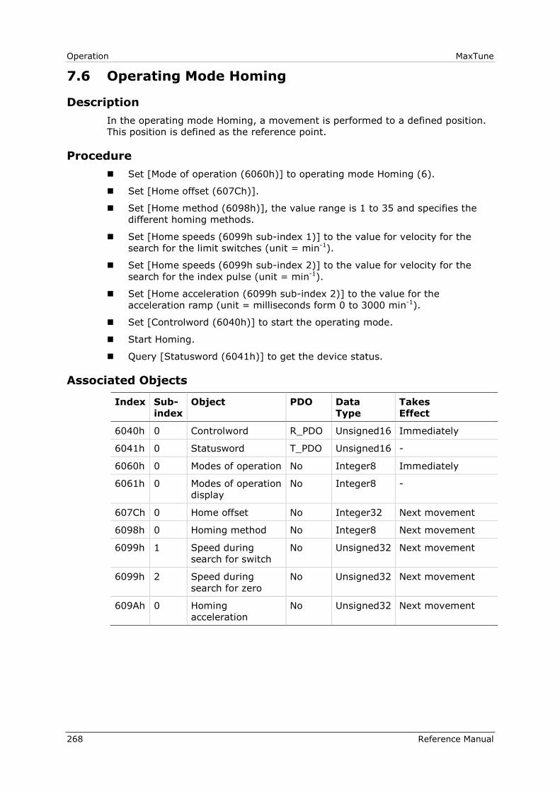
Operation MaxTune
268 Reference Manual
7.6 Operating Mode Homing
Description
In the operating mode Homing, a movement is performed to a defined position.
This position is defined as the reference point.
Procedure
Set [Mode of operation (6060h)] to operating mode Homing (6).
Set [Home offset (607Ch)].
Set [Home method (6098h)], the value range is 1 to 35 and specifies the
different homing methods.
Set [Home speeds (6099h sub-index 1)] to the value for velocity for the
search for the limit switches (unit = min-1).
Set [Home speeds (6099h sub-index 2)] to the value for velocity for the
search for the index pulse (unit = min-1).
Set [Home acceleration (6099h sub-index 2)] to the value for the
acceleration ramp (unit = milliseconds form 0 to 3000 min-1).
Set [Controlword (6040h)] to start the operating mode.
Start Homing.
Query [Statusword (6041h)] to get the device status.
Associated Objects
Index Sub-
index
Object PDO Data
Type
Takes
Effect
6040h 0 Controlword R_PDO Unsigned16 Immediately
6041h 0 Statusword T_PDO Unsigned16 -
6060h 0 Modes of operation No Integer8 Immediately
6061h 0 Modes of operation
display
No Integer8 -
607Ch 0 Home offset No Integer32 Next movement
6098h 0 Homing method No Integer8 Next movement
6099h 1 Speed during
search for switch
No Unsigned32 Next movement
6099h 2 Speed during
search for zero
No Unsigned32 Next movement
609Ah 0 Homing
acceleration
No Unsigned32 Next movement
MaxTune Operation
Reference Manual 269
Example: Homing
Starting the Operating Mode
The operating mode must be set in the parameter Mode of operation (6060h).
Writing the parameter value activates the operating mode.
The movement is started via the Controlword.
Controlword
Bits 4 in the parameter Controlword (6040h) starts a movement, bit 8
terminates the movement.
Parameter Value Meaning
Bit 4 = Homing operation start Start Homing
Bit 5 = Reserved Not relevant for this operating mode
Bit 6 = Reserved Not relevant for this operating mode
Bit 8 = Halt Stop movement with Halt
Terminating the Operating Mode
The operating mode is terminated when the motor is at a standstill and one of
the following conditions is met:
Homing successful
Stop caused by Halt or Quick Stop
Stop caused by an error
Statusword
Information on the current movement is available via bits 10 and 12–15 in the
parameter Statusword (6041h).
Parameter Value Meaning
Bit 10 = Target reached 0 = Homing not completed
1 = Homing completed
Bit 12 = Homing attained 1 = Homing successfully completed
Bit 13 = Homing error 1 = Homing error
Bit 14 = Manufacturer-specific
Bit 15 = Manufacturer-specific
Operation MaxTune
270 Reference Manual
Example Node Address 1
Work Step
COB ID / Data
» Velocity for searching the limit switch to 100
601 / 23 99 60 01 64 00 00 00
« 581 / 60 99 60 01 00 00 00 00
» Velocity for moving away from switch to 10
601 / 23 99 60 02 0A 00 00 00
« 581 / 60 99 60 02 00 00 00 00
» NMT Start remote node
0 / 01 00
« T_PDO1 with Statusword
181 / 31 62
» Enable power stage with R_PDO1
201 / 00 00
201 / 06 00
201 / 0F 00
« T_PDO1 (operating state: 6 operation enabled)
181 / 37 42
» Starting the operating mode
601 / 2F 60 60 00 06 00 00 00
« 581 / 60 60 60 00 00 00 00 00
» Check operating mode *
601 / 40 61 60 00 00 00 00 00
« Operating mode active
581 / 4F 61 60 00 06 61 01 00
» Select method 17
601 / 2F 98 60 00 11 00 00 00
« 581 / 60 98 60 00 00 00 00 00
» Start reference movement (Homing operation start)
201 / 1F 00
« T_PDO1 reference movement active
181 / 37 02
« T_PDO1 reference movement terminated
181 / 37 D6
* Note: The operating mode must be checked until the device has activated the
specified operating mode.
MaxTune Operation
Reference Manual 271
7.7 Operating Mode Profile Velocity
Description
In the operating mode Profile Velocity, a movement is made with a desired
target velocity.
Procedure
Set [Mode of operation (6060 )] to operating mode Profile Velocity (3).
Set [Controlword (6040h)] to start the operating mode.
Set [Target velocity (60FFh)] to the target velocity. If the power stage is
enabled, the new target velocity will become active immediately and the
movement will start. The value is reset to zero if the operating mode is
changed, the power stage is disabled or a Quick Stop is triggered.
Query [Statusword (6041h)] to get the device status.
Optional
Query [Velocity demand value (606Bh)] to get the reference velocity.
Query [Velocity actual value (60C3h)] to get the actual velocity.
Set [Velocity window (606Dh)] to the value of the velocity window.
Set [Velocity window time (606Eh)] to the duration in the velocity window
required to consider the velocity to have been reached unit = milliseconds).
Query [Velocity threshold (60F4h)] to set the standstill window.
Associated Objects
Index Sub-
index
Object PDO Data
Type
Takes
Effect
6040h 0 Controlword R_PDO Unsigned16 Immediately
6041h 0 Statusword T_PDO Unsigned16 -
6060h 0 Modes of Operation No Integer8 Immediately
6061h 0 Modes of Operation
Display
No Integer8 -
606Bh 0 Velocity Demand
Value
No Integer32 -
606Ch 0 Velocity Actual Value No Integer32 -
606Dh 0 Velocity Window No Unsigned16 Immediately
606Eh 0 Velocity Window Time No Unsigned16 Immediately
606Fh 0 Velocity Threshold No Unsigned16 Immediately
60FFh 0 Target Velocity No Integer32 Immediately
Operation MaxTune
272 Reference Manual
Example: Profile Velocity
Starting the Operating Mode
The operating mode must be set in the parameter Mode of operation (6060h).
Writing the parameter value activates the operating mode.
The parameter Target velocity (60FFh) starts the movement.
Parameter
Name
Description Data Type
R/W
Target Velocity Target velocity for operating mode Profile
Velocity
Changed settings become active immediately.
Integer32
Read/Write
Controlword
Bit 8 in parameter Controlword (6040h) is used to stop a movement with Halt.
Parameter Value Meaning
Bit 4 = Reserved Not relevant for this operating mode
Bit 5 = Reserved Not relevant for this operating mode
Bit 6 = Reserved Not relevant for this operating mode
Bit 8 = Halt Stop movement with Halt
Bit 9 = Change on setpoint Not relevant for this operating mode
Terminating the Operating Mode
The operating mode is terminated when the motor is at a standstill and one of
the following conditions is met:
Stop caused by Halt or Quick Stop
Stop caused by an error
Statusword
Information on the current movement is available via bits 10 and 12 in the
parameter Statusword (6041h).
Parameter Value Meaning
Bit 10 = Target reached 0 = Target velocity not reached
1 = Target velocity reached
Bit 12 = Velocity 0 = Velocity > 0
1 = Velocity = 0
Bit 14 = Manufacturer-specific
Bit 15 = Manufacturer-specific

MaxTune Operation
Reference Manual 273
Example Node Address 1
Work Step
COB ID / Data
» NMT Start remote node
0 / 01 00
« T_PDO3 with Statusword
381 / 31 66 00 00 00 00
» Enable power stage with R_PDO3
201 / 00 00 00 00 00 00
201 / 06 00 00 00 00 00
201 / 0F 00 00 00 00 00
« T_PDO3 (operating state: 6 Operation Enabled)
181 / 37 46 00 00 00 00
» Starting the operating mode
601 / 2F 60 60 00 03 00 00 00
« 581 / 60 60 60 00 00 00 00 00
» Check operating mode *
601 / 40 61 60 00 00 00 00 00
« Operating mode active
581 / 4F 61 60 00 00 00 00 00
» R_PDO3: Specification of target velocity 1000
301 / E8 03 00 00
« T_PDO2 with Statusword and velocity actual value
381 / 37 02 00 00 00 00
« Target velocity reached
381 / 37 06 E8 03 00 00
» Terminate operating mode with Quick Stop with R_PDO3
401 / 0B 00 00 00 00 00
« T_PDO3 with Statusword
381 / 17 66 00 00 00 00
» Clear Quick Stop with R_PDO3
401 / 0F 00 00 00 00 00
« T_PDO3 with Statusword
381 / 37 46 00 00 00 00
* Note: The operating mode must be checked until the device has
activated the specified operating mode.
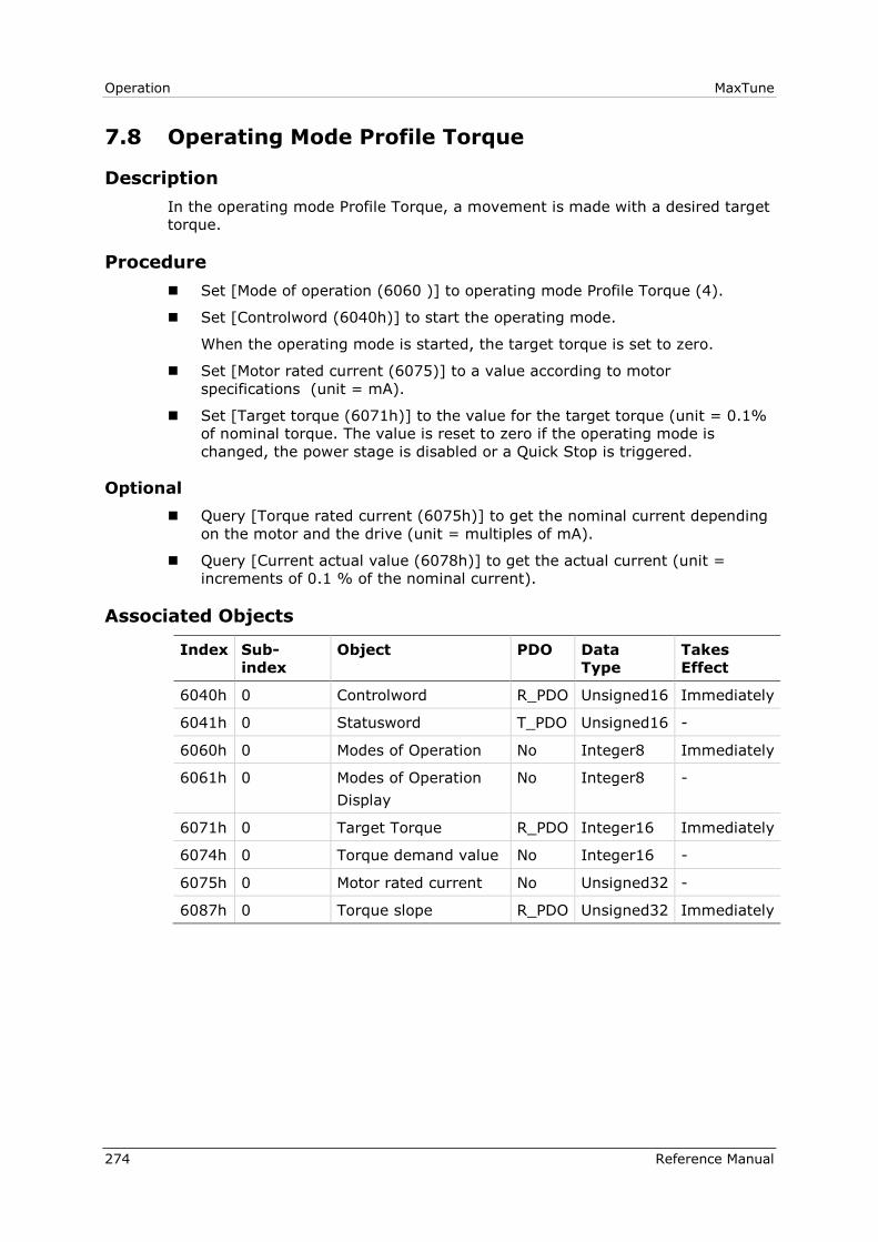
Operation MaxTune
274 Reference Manual
7.8 Operating Mode Profile Torque
Description
In the operating mode Profile Torque, a movement is made with a desired target
torque.
Procedure
Set [Mode of operation (6060 )] to operating mode Profile Torque (4).
Set [Controlword (6040h)] to start the operating mode.
When the operating mode is started, the target torque is set to zero.
Set [Motor rated current (6075)] to a value according to motor
specifications (unit = mA).
Set [Target torque (6071h)] to the value for the target torque (unit = 0.1%
of nominal torque. The value is reset to zero if the operating mode is
changed, the power stage is disabled or a Quick Stop is triggered.
Optional
Query [Torque rated current (6075h)] to get the nominal current depending
on the motor and the drive (unit = multiples of mA).
Query [Current actual value (6078h)] to get the actual current (unit =
increments of 0.1 % of the nominal current).
Associated Objects
Index Sub-
index
Object PDO Data
Type
Takes
Effect
6040h 0 Controlword R_PDO Unsigned16 Immediately
6041h 0 Statusword T_PDO Unsigned16 -
6060h 0 Modes of Operation No Integer8 Immediately
6061h 0 Modes of Operation
Display
No Integer8 -
6071h 0 Target Torque R_PDO Integer16 Immediately
6074h 0 Torque demand value No Integer16 -
6075h 0 Motor rated current No Unsigned32 -
6087h 0 Torque slope R_PDO Unsigned32 Immediately

MaxTune Operation
Reference Manual 275
Example: Profile Torque
Starting the Operating Mode
The operating mode must be set in the parameter Mode of operation (6060h).
Writing the parameter value activates the operating mode.
The parameter Target torque (6071h) starts the movement.
Parameter
Name
Description Data Type
R/W
Target Torque Target torque for operating mode Profile
Torque.
100.0% corresponds to the continuous stall.
In increments of 0.1%.
Changed settings become active immediately.
Integer16
Read/Write
Controlword
Bit 8 in parameter Controlword (6040h) is used to stop a movement with Halt.
Parameter Value Meaning
Bit 4 = Reserved Not relevant for this operating mode
Bit 5 = Reserved Not relevant for this operating mode
Bit 6 = Reserved Not relevant for this operating mode
Bit 8 = Halt Stop movement with Halt
Bit 9 = Change on setpoint Not relevant for this operating mode
Terminating the Operating Mode
The operating mode is terminated when the motor is at a standstill and one of
the following conditions is met:
Stop caused by Halt or Quick Stop
Stop caused by an error
Statusword
Information on the movement is available via bit 10 in the parameter
Statusword (6041h).
Parameter Value Meaning
Bit 10 = Target reached 0 = Target torque not reached
1 = Target torque reached
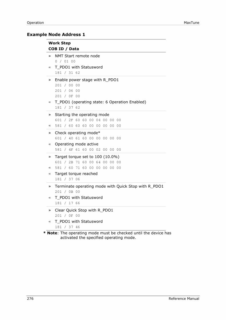
Operation MaxTune
276 Reference Manual
Example Node Address 1
Work Step
COB ID / Data
» NMT Start remote node
0 / 01 00
« T_PDO1 with Statusword
181 / 31 62
» Enable power stage with R_PDO1
201 / 00 00
201 / 06 00
201 / 0F 00
« T_PDO1 (operating state: 6 Operation Enabled)
181 / 37 62
» Starting the operating mode
601 / 2F 60 60 00 04 00 00 00
« 581 / 60 60 60 00 00 00 00 00
» Check operating mode*
601 / 40 61 60 00 00 00 00 00
« Operating mode active
581 / 4F 61 60 00 02 00 00 00
» Target torque set to 100 (10.0%)
601 / 2B 71 60 00 64 00 00 00
« 581 / 60 71 60 00 00 00 00 00
« Target torque reached
181 / 37 06
» Terminate operating mode with Quick Stop with R_PDO1
201 / 0B 00
« T_PDO1 with Statusword
181 / 17 66
» Clear Quick Stop with R_PDO1
201 / 0F 00
« T_PDO1 with Statusword
181 / 37 46
* Note: The operating mode must be checked until the device has
activated the specified operating mode.