maxrefdes67#: universal input micro plc sheets/maxim... · small micro plc form factor marries this...
TRANSCRIPT

System Board 6185MAXREFDES67#: UNIVERSAL INPUT MICRO PLC
Overview
The MAXREFDES67# reference design is a complete universal analog input for industrial applications. This unique 24-bit front-end accepts bipolar voltage and current, resistance temperature detector (RTD) and thermocouple (TC) inputs. Built in Maxim Integrated’s ultra-small Micro PLC form factor, the MAXREFDES67# performs with a effective resolution up to 22.3 bits with temperature error as low as ±0.1% across a range of -40°C to 150°C.
To enhance ease of use, the innovative system architecture switches all signals on board, meaning that the connector requires no jumpers or additional connections, regardless of the type of connection. In addition, the system features Maxim Integrated’s Beyond-the-Rails feature in all signal-chain elements. Beyond the Rails reduces the need for large power supplies, allowing each element to accept large input voltages while running from a low-voltage power rail.
The board features a micro USB connector for quick connection to a PC for evaluation. In addition, the board requires a 24V power supply, from a power supply or from the included AC/DC wall adapter. Refer to the Details tab for more information and performance data. Design files and firmware can be downloaded from the Design Resources tab.
Features• High accuracy• -10V to +10V ±20% voltage inputs• -20mA to +20mA ±20% current inputs• RTD and TC tested temperature range (-40°C to +150°C)• Software-controlled input type• 24V input protection• Isolated power and data

• Board and sensor calibration• Micro PLC form factor• Device drivers• Example C source code• Test data
Competitive Advantages• Flexibility• Accelerated time to market• Ease of use
Applications• Industrial control and automation• Process control• PLC
Enlarge+
MAXREFDES67# System Board
MAXREFDES67# Reference Design Block Diagram

Enlarge+
MAXREFDES67# Circuit Block Diagram

System Board 6185MAXREFDES67#: UNIVERSAL INPUT MICRO PLC
Details
IntroductionThe universal analog input is the most functional, ubiquitous element in factory automation. The ability to flexibly measure current, voltage, RTDs, and TCs makes the universal input an indispensable piece in any installation. In parallel, Industry 4.0 marks a sea change in industrial architectures, characterized by distributed, intelligent control systems. Industry 4.0 allows for highly configurable, highly modular factories, which accept an ever increasing number of sensor inputs while operating at a higher output than ever before. Building a universal input in the ultra-small micro PLC form factor marries this indispensible element with the key concepts of Industry 4.0. Furthermore, this board requires a number of highly integrated analog and mixed signal products providing high performance with ultra-low power consumption in an ultra-small package. MAXREFDES67# is Maxim’s micro PLC, universal analog input card.
The MAXREFDES67# features an analog input that supports voltage, current, RTD, and thermocouple input signals with isolated power and data. The MAXREFDES67# design integrates two beyond-the-rail SPST analog switches (MAX14759), two beyond-the-rail SPDT analog switches (MAX14763), a dual beyond-the-rail buffer (MAX44267), a quad low-noise low-power op amp (MAX44245), a digital thermometer (MAX31723), a 24-bit 6-channel ADC (MAX11254) with internal PGA buffers, an ultra-high-precision 4.096V voltage reference (MAX6126), a low-power precision op amp (MAX44244), 2.75kVRMS data isolation (MAX14930 and MAX14932), a STM32F4 microcontroller, a FTDI USB-UART bridge, a high-efficiency DC-DC converter (MAX17552), and isolated/regulated +15V and +3.6V power rails (MAX17498C and two MAX17651s). The entire system typically operates at less than 500mW and fits into a space roughly the size of a credit card. While targeted for industrial, micro PLC applications, the MAXREFDES67# may be used in any application that requires high-accuracy analog-to-digital conversion. A block diagram of the system is shown in Figure 1 and Figure 2.
MAXREFDES67# System Board

Figure 1. The MAXREFDES67# reference design block diagram.
Enlarge+

Figure 2. The MAXREFDES67# reference design input circuit block diagram.
Detailed Description of HardwareThe power requirement is shown in Table 1.
Table 1. Power Requirement for the MAXREFDES67# Reference Design
Power Type Input Voltage (V) Input Current (mA, typ)
On-board isolated power 24 20
Note: STM32 and FTDI are powered by USB separately
The MAXREFDES67# reference design is a universal analog input card with isolated power and data. It supports voltage, current, RTD (PT100 and PT1000), and thermocouple (K type) inputs as shown in the configuration diagram of Figure 3. The input circuitry utilizes the digitally controlled analog switches (MAX14759 and MAX14763) to make the appropriate electrical connections for different types of input signals, thus relieving the need for any additional jumpers on the terminal block. The dual beyond-the-rail op amp (MAX44267) buffers the input signal. The quad low-noise low-power op amp (MAX44245) attenuates and also adds 1.5V offset to the input signals. The offset voltage is needed because the ADC is set up to measure positive signals. This setup eliminates the need for a negative voltage reference and voltage supply. The 10:1.15 attenuation is for the -12V to +12V voltage signal, and the 10:9.53 attenuation is for the current, RTD, and TC input signals. The 10:1.15 attenuated signal from the output of the MAX44245 connects to channel 0 of the ADC, and the signal with 10:9.53 attenuation connects to channel 1 of the ADC. The STM32 controller determines which channel to read depending on the input selected. The MAX11254 is a highly integrated, 24-bit, 6-channel ADC with an integrated analog input PGA. The ADC’s reference input is driven by an ultra-high-precision voltage reference, the MAX6126,

with 0.02% initial accuracy and a 3ppm/°C maximum temperature coefficient (tempco). An on-board digital thermometer (MAX31723) is placed close to the input terminal block to determine the temperature at the input port and provide the cold junction temperature of the thermocouple.
The MAXREFDES67# uses the ultra-efficient MAX17498C to generate the isolated +17.5V and +7.5V rails from a 24V supply. The two MAX17651 devices provide post-regulated +15V, +3.6V rails. The MAX14930/MAX14932 digital data isolators provide data isolation. The combined power and data isolation achieved is 300V working voltage in pollution degree 2 environment based on material class IIIb per IEC 60950.
The MAX17552 step-down DC-DC converter converts the +5V supply from the USB to +3.3V and powers the STM32 microcontroller and FTDI USB-UART bridge.
A PT100 RTD and a K-type thermocouple are included in the MAXREFDES67# package. For the thermocouple, the yellow wire is the positive signal and the red wire is the negative signal.
Figure 3. The MAXREFDES67# input configurations.
Detailed Description of FirmwareThe MAXREFDES67# uses the on-board STM32F4 microcontroller to control the analog switch, read temperature from the digital thermometer, communicate with the ADC, and save the ADC samples in the on-chip SRAM. Users read the sampled data through a terminal program, allowing analysis on any third-party software. Users can also perform system and sensor calibrations through a terminal program. The red color V connector on the board is provided for RTD input calibration. The simple process flow is shown in Figure 4. The firmware is written in C using the Keil µVision5 tool.
RMS
REF

Figure 4. The MAXREFDES67# firmware flowchart.
The firmware accepts calibration and sampling commands, and is capable of downloading blocks of sampled data to a standard terminal program via a virtual COM port. The complete source code is provided to speed up customer development. Code documentation can be found in the corresponding firmware platform files.
Quick StartRequired equipment:
• Windows® PC with a USB port• MAXREFDES67# board• 24V power supply, provided

• PT100 RTD, provided
ProcedureThe reference design is fully assembled and tested. Follow the steps below to verify board operation:
1. The MAXREFDES67# utilizes the FTDI USB-UART bridge IC. If Windows cannot automatically install the driver for the FTDI USB-UART bridge IC, the driver is available for download from www.ftdichip.com/Drivers/D2XX.htm.
2. Connect the 24V power supply to the J501 connector on the MAXREFDES67# board.3. Connect the RTD across pin 2 and pin 3 of the terminal block.4. Connect the USB cable from the PC to the MAXREFDES67# board.5. Open Hyperterminal or a similar terminal program on the PC. Find the appropriate COM
port, usually a higher number port, such as COM4 or COM6, and configure the connection for 115200, 8-N-1 with no flow control.
6. The MAXREFDES67# software will display a menu (Figure 5)7. Press 1 in the terminal program to select Data Acquisition.8. Press 2 to select RTD PT-100 2-wire input.9. Press 0 to select Continuous Sampling.
10. Verify the measured temperature is approximately the room temperature.
Figure 5. Terminal program main menu.
Lab MeasurementsEquipment used:
• K-type Thermocouple (Omnitec EC3TC)• PT-100 RTD 1/10 DIN (Omega P-M-1/10-1/4-6-0-G-3)• Voltage calibrator DVC-8500

• Fluke 189 Multimeter• Fluke 7341 Calibration Bath• Omega HH41 Thermometer• ETI Reference Thermometer• Fluke 724 Temperature Calibrator• Windows PC, a USB port• MAXREFDES67# board• +24V power supply
Voltage calibrator DVC-8500 and Fluke 189 multimeter were used to calibrate the inputs of the MAXREFDES67#.
Figure 6, Figure 7, Figure 8, Figure 9 show the DC histogram for 0V voltage input and 0A current input sampled at 1.9sps and 1ksps.
Figure 6. Voltage input DC histogram; a 0V input signal; a 1.9sps sample rate; 16384 samples; a code spread of 24 LSBs; a standard deviation of 3.273 (Effective Resolution = 22.3 bits); and the mean of 8µV.
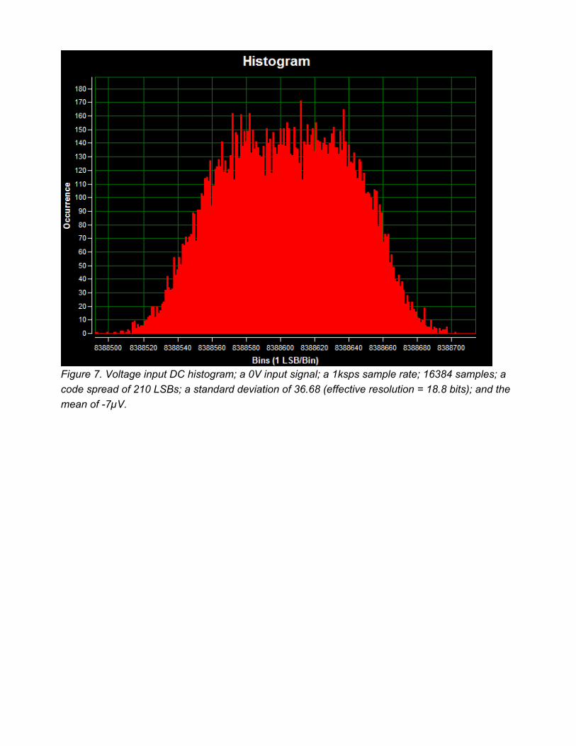
Figure 7. Voltage input DC histogram; a 0V input signal; a 1ksps sample rate; 16384 samples; a code spread of 210 LSBs; a standard deviation of 36.68 (effective resolution = 18.8 bits); and the mean of -7µV.

Figure 8. Current input DC histogram; a 0A input signal; a 1.9sps sample rate; 16384 samples; a code spread of 44 LSBs; a standard deviation of 5.643 (effective resolution = 21.5 bits); and the mean of 357nA.

Figure 9. Current input DC histogram; a 0A input signal; a 1ksps sample rate; 16384 samples; a code spread of 441 LSBs; a standard deviation of 54.49 (effective resolution = 18.2 bits); and the mean of 470nA.
Figure 10 shows the temperature error measured by the MAXREFDES67# RTD input versus temperature referenced to three different thermometers. The references are the Omega HH41 thermometer, the ETI reference thermometer, and Fluke 724 temperature calibrator, respectively. The MAXREFDES67# connected RTD probe (Omega P-M-1/10-1/4-6-0-G-3) was placed in the Fluke 7341 calibration bath and calibrated at 20°C.
Figure 11 shows the temperature error measured by the MAXREFDES67# thermocouple input versus temperature referenced to the same three reference thermometers, the Omega HH41 thermometer, the ETI reference thermometer, and Fluke 724 temperature calibrator, respectively. The MAXREFDES67# connected K-type thermocouple probe was placed in the Fluke 7341 and calibrated at 20°C.
Click on the link below to see the NIST traceable certificate of calibration for the Omega HH41 thermometer used as a reference.
NIST traceable certificate of calibration for the Omega HH41 thermometer

Figure 10. MAXREFDES67# error vs. temperature, using an Omega P-M-1/10-1/4-6-0-G-3, 4-wire RTD calibrated at 20°C.
Figure 11. MAXREFDES67# error vs. temperature, using an Omnitec EC3TC, K-type thermocouple calibrated at 20°C.

For both Figure 10 and 11, the blue data used the Omega HH41 thermometer as a reference. The green data used the ETI reference thermometer as a reference. The red data used the Fluke 724 temperature calibrator as the reference.
Windows is a registered trademark and registered service mark of Microsoft Corporation.
Reference
1. The new generation of manufacturing production is called Industry 4.0 in Germany and Smart Manufacturing System elsewhere. See, Securing the future of German manufacturing industry, Recommendations for implementing the strategic initiative INDUSTRIE 4.0, Final report of the Industrie 4.0 Working Group, Industry 4.0 Working Group, Acatech National Academy of Science and Engineering, April 2013, www.acatech.de/fileadmin/user_upload/Baumstruktur_nach_Website/Acatech/root/de/Material_fuer_Sonderseiten/Industrie_4.0/Final_report__Industrie_4.0_accessible.pdf. Henceforth cited as Industrie 4.0. Although the Industrie 4.0 report is focused on Germany, the implications of the German research and findings are recognized for industry in other countries. See also Ferber, Stefan, “Industry 4.0 – Germany takes the first steps toward the next industrial revolution,” Bosch Software Group, Blogging the Internet of Things, October 16, 2012, http://blog.bosch-si.com/industry-4-0-germany-takes-first-steps-toward-the-next-industrial-revolution/.
There are many sources for Smart Manufacturing Leadership. An interesting summary report of issues and topics can be found at the Smart Manufacturing Leadership Coalition Committee Working Meeting, Minneapolis, MN, U.S., Thursday, October 20, 2011, https://smartmanufacturingcoalition.org/sites/default/files/smlc_meeting.pdf
Also see, Implementing 21st Century Smart Manufacturing, Workshop Summary Report, Smart Manufacturing Leadership Coalition, June 24, 2011, https://smartmanufacturingcoalition.org/sites/default/files/implementing_21st_century_smart_manufacturing_report_2011_0.pdf.
A simple web search on the topic will reveal considerably more references.
7/31/2015http://www.maximintegrated.com/en/design/reference-design-center/system-board/6185.ht...