maximum usable frequency usable frequency … study muf and its variants? • despite the...
TRANSCRIPT

Maximum Usable Frequency
Ken Larson KJ6RZ
August 21, 2014
0
5
10
15F
req
uen
cy (
MH
z)
6 12 18 24Time (Hours)
MaximumUsableFrequency
Lowest Usable Frequency
UsableFrequency Window
UsableFrequency Window
SolarFlare
Radio Blackout

Reliable HF Communications
• Meaning: Successfully transmitting and receiving messages any time
– Day or night
– Regardless of HF conditions
• Specifically
– 24 hours a day
– 7 days a week
– Throughout the 11 year solar cycle.

Why Study MUF and its Variants?
• Despite the difficulties
• WWII HF radio operators were successful
– 90% of the time, in getting their radio traffic through, and
– Their radios were not nearly as good as what we have today.
• For over 50 years, HF was the only viable means of communications
in many remote areas of the world.
– Australia outback,
– South Pacific
– Ships at sea
• The goal is to achieve the same level of success that they enjoyed.

Upper Atmosphere Ionization
• Solar EUV & X-ray radiation ionizes atoms in the upper atmosphere.
• Neutral atom absorbs some of the radiation.
• Absorbed energy excites an electron in the neutral atom.
• Electron breaks free from the atom.
• Result: free electron and a positively charged ion.
EUV & X-RAY
Neutral Atom
ION
+
-Electron

Formation of the Ionosphere
EARTH
IONOSPHERE
EUV & X-RAY
• EUV & X-ray radiation intense at top of atmosphere but few atoms to ionize.
• As the radiation penetrates deeper into the atmosphere, the density of the atmosphere increases (more atoms) resulting in higher levels of ionization.
• Ionization process continuously weakens EUV & X-ray radiation, thus the number of atoms ionized decreases as the radiation penetrates further into the atmosphere, even though the density of atoms continues to increases.
• Consequently, ionizations levels drop and eventually disappear.

Ionosphere Ionization Levels
• Solar Flux Index SFI provides a good measure of solar activity and level of ionization. (2.8 GHz,10.7 cm)
• http://www.solarham.net
• 50 < SFI <300
• SFI = 60 very poor radio conditions
• SFI = 200 very good conditions
• Neutral atmosphere is hundreds to billions of times more dense than the ionosphere.
• The ionosphere is very thin and wispy. Easily blow around by very high altitude winds.
Alt
itu
de
(Mile
s)
F2 Region
E Region
D Region55
75
180
100
370
600
F1 Region
30
Ionosphere
Density: Electrons / cm
4 5 610 10 10 101 310210
31014 810
Density: Neutral Atoms / cm3
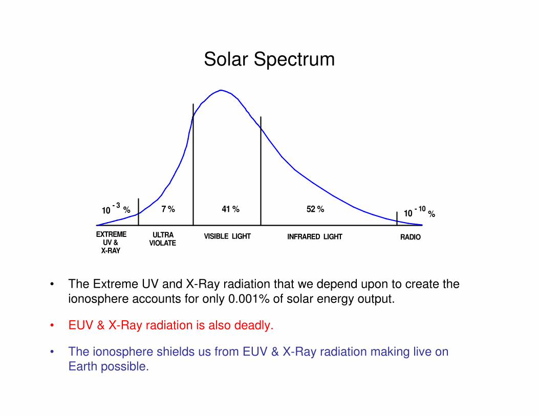
Solar Spectrum
ULTRAVIOLATE
VISIBLE LIGHT INFRARED LIGHT RADIOEXTREME UV & X-RAY
7 % 41 % 52 %10
- 10%10
- 3%
• The Extreme UV and X-Ray radiation that we depend upon to create the
ionosphere accounts for only 0.001% of solar energy output.
• EUV & X-Ray radiation is also deadly.
• The ionosphere shields us from EUV & X-Ray radiation making live on
Earth possible.

Why We Have HF Radio
• Increasing levels of ionization from the bottom to the middle of the ionosphere is why we have HF radio.
• If it were not for this characteristic of the ionosphere:
– We would never of heard of Marconi,
– There would not be an ARRL,
– There probably would not be amateur radio.
EARTH
IONOSPHERE
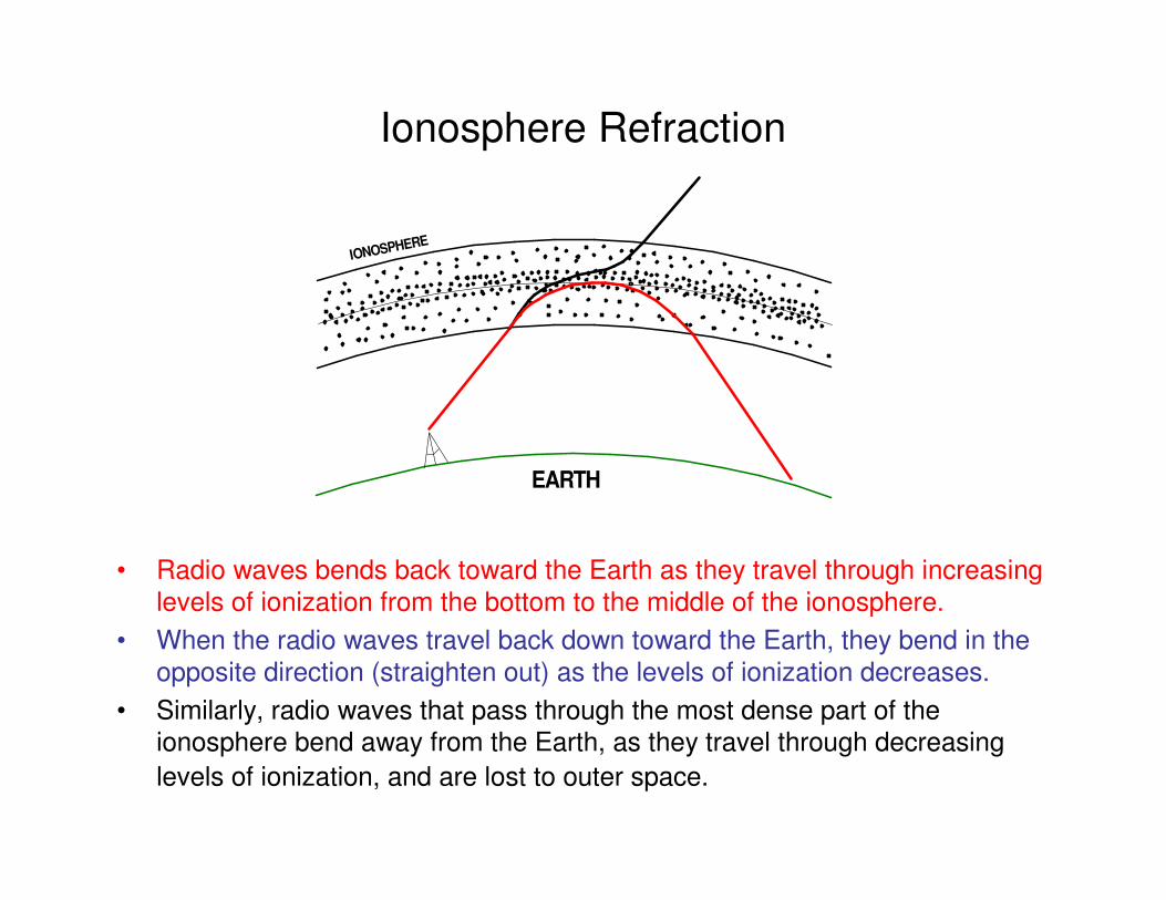
Ionosphere Refraction
EARTH
IONOSPHERE
• Radio waves bends back toward the Earth as they travel through increasing
levels of ionization from the bottom to the middle of the ionosphere.
• When the radio waves travel back down toward the Earth, they bend in the
opposite direction (straighten out) as the levels of ionization decreases.
• Similarly, radio waves that pass through the most dense part of the
ionosphere bend away from the Earth, as they travel through decreasing
levels of ionization, and are lost to outer space.

Frequency Dependency of Refraction
• A radio signal penetrates further into the ionosphere as the transmitting
frequency increases,
• Until the MUF is reached.
• Transmitting at a frequency greater than MUF results in the signal passing
completely through the ionosphere and lost to outer space.
EARTH
IONOSPHERE
15m
80m 40m20m
20m = MUF

The Maximum Usable Frequency is:
• The highest frequency radio signal
• Capable of propagating through the ionosphere
• From one specific radio station to an other
EARTH
ELEVATION
ANGLE
SKYWAVE
F LAYER
STATION - A STATION - B
E

MUF Equation
• fc = Critical Frequency of the ionosphere at the refraction point.
� Critical Frequency is the highest frequency signal that can be transmitted straight up and reflected from the ionosphere.
• E = The angle of elevation of the signal radiating from your antenna.
• We will use this equation a lot in its various forms !
cfMUF
sin E=

Elevation Angle E
EARTH
ELEVATION
ANGLE
SKYWAVE
F LAYER
STATION - A STATION - B
E
cfMUF
sin E=

Critical Frequency
• Critical Frequency fc is the highest frequency signal that can be transmitted straight up and reflected back to Earth.
cfMUF
sin E= c c c
co
f f fMUF f
sin E sin90 1= = = =
cMUF f≥
EARTH
F LAYER
LocalCommunications
So how do you know what the critical frequency is at a particular time of day?
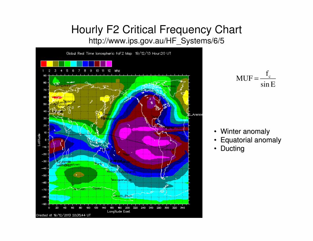
Hourly F2 Critical Frequency Charthttp://www.ips.gov.au/HF_Systems/6/5
cfMUF
sin E=
•• Winter anomalyWinter anomaly
•• Equatorial anomalyEquatorial anomaly
•• DuctingDucting

MUF Depends on the Path
EARTH
F LAYER
HomeStation
Station - 1
Station - 2
E2
E1
• MUF increases as the angle E gets smaller.
• Thus MUF2 is greater than MUF1.
• Lets take a look at an example.
cfMUF
sin E=

MUF Example 1 - CESN
• What is the MUF from Thousand Oaks to San Bernardino?
• What is the MUF from Thousand Oaks to Sacramento?
• First must determine the elevation angle E.
(CESN = California Emergency Services Net.)
EARTH
F LAYER
Thousand Oaks
SanBernardino ~ 80 mi Sacramento
~ 350 mi
E1 E2
cfMUF
sin E=
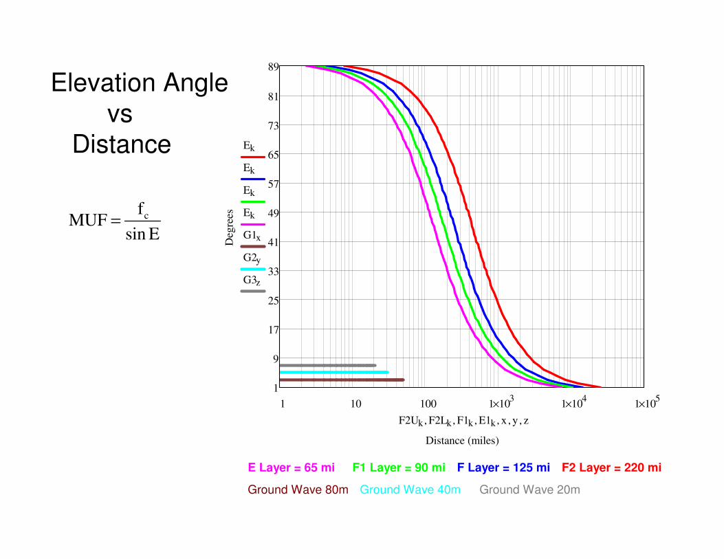
Elevation Angle
vs
Distance
cfMUF
sin E=
1 10 100 1 103
× 1 104
× 1 105
×
1
9
17
25
33
41
49
57
65
73
81
89
Distance (miles)
Deg
rees
Ek
Ek
Ek
Ek
G1x
G2y
G3z
F2Uk F2Lk, F1k, E1k, x, y, z,
E Layer = 65 mi F1 Layer = 90 mi F Layer = 125 mi F2 Layer = 220 mi
Ground Wave 80m Ground Wave 40m Ground Wave 20m

Calculating
Elevation
Angle
Sacramento = 350 mi
E2 = 45 deg
San Bernardino = 80 mi
E1 = 77 deg
cfMUF
sin E=
1 10 100 1 103
× 1 104
× 1 105
×
1
9
17
25
33
41
49
57
65
73
81
89
Distance (miles)
Deg
rees
Ek
Ek
Ek
Ek
G1x
G2y
G3z
F2Uk F2Lk, F1k, E1k, x, y, z,
E Layer = 65 mi F1 Layer = 90 mi F Layer = 125 mi F2 Layer = 220 mi
Ground Wave 80m Ground Wave 40m Ground Wave 20m

Determine Critical Frequency
• E1 = 77 deg
• E2 = 45 deg
• fc = ?
EARTH
F LAYER
Thousand Oaks
SanBernardino ~ 80 mi Sacramento
~ 350 mi
E1 E2
cfMUF
sin E=

Determine Critical Frequency
• On 6/25/2014 Critical Freq is about 6.5 MHz for California
cfMUF
sin E=
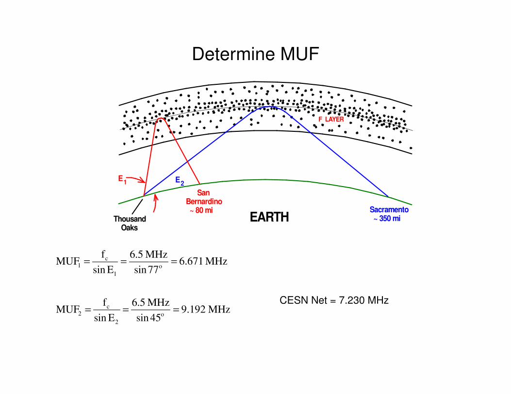
Determine MUF
CESN Net = 7.230 MHz
EARTH
F LAYER
Thousand Oaks
SanBernardino ~ 80 mi Sacramento
~ 350 mi
E1 E2
c1 o
1
c2 o
2
f 6.5 MHzMUF 6.671 MHz
sin E sin77
f 6.5 MHzMUF 9.192 MHz
sin E sin 45
= = =
= = =

Example – 2 The 80 meter Episode
• 80 meters is a night time band.
• In fact, 80 meters is often open all through the night even
though higher frequency bands shut down.
• It would be fun to operate 80 meters during the evening.
• Even operating all night long!

An 80 meter Inverted V Antenna Was Built
32 feet = 0.125 Wavelength

80 meter Antenna Radiation Pattern
• Good NVIS antenna
• Can talk to stations close in and throughout southern California
• At 70 degrees maybe stations in New Mexico, Utah, Oregon, etc.
• A good antenna
- 3 db
90
3030
60 60
- 6 db
80 meter Inverted V Antenna 1/8 Wavelenth Above Ground
90

80 meter Antenna Doesn't Work at Night !
• Around 10 PM the antenna stops working.
• Plenty of stations being heard on 80 meters.
• The Critical Frequency is approximately 3 MHz.
• MUF apparently not a problem ???
• Is the high angle radiation from the Inverted V antenna a problem?
• To find out, solve the MUF equation for angle instead of frequency.
• The result is an equation for Maximum Usable Angle (EM) .

Maximum Usable Angle
• Maximum Usable Angle is the highest angle signal that can be transmitted,
• At an operating frequency of fo , and
• Still be refracted by the ionosphere if the critical frequency is fc .
EARTH
F LAYER
STATION - A STATION - B
E M
1 cM
o
fMUA E sin
f
−
= =
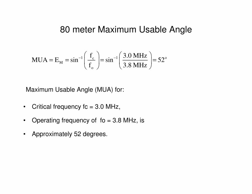
80 meter Maximum Usable Angle
Maximum Usable Angle (MUA) for:
• Critical frequency fc = 3.0 MHz,
• Operating frequency of fo = 3.8 MHz, is
• Approximately 52 degrees.
1 1 ocM
o
f 3.0 MHzMUA E sin sin 52
f 3.8 MHz
− −
= = = =

MUA Too Low For The 80 m Inverted V Antenna
• What needs to be done to operate late at night on 80 meters?
- 3 db
90
3030
60 60
- 6 db
80 meter Inverted V Antenna 1/8 Wavelenth Above Ground
90
MUA = 52 deg @ fc = 3 MHz

80 m Vertical Needed For Late Night Operation
• Vertical antenna can work down to a critical frequency of ~ 1 MHz.
• Well into the early hours of the morning.
• Two 80 m antennas required for emergency communications.
- 3 db
90
3030
60 60
- 6 db
1/4 Wave Vertical Antenna
MUA = 52 deg @ fc = 3 MHz
MUA = 32 deg @ fc = 2 MHz
MUA = 15 deg @ fc = 1 MHz

How Low Does The Critical Frequency Get?

Skip Distance (Zone)
• Increasing angle E shortens the distance transmitted in a single hop.
• The shortest distance (from Point A to B) occurs when E = MUA.
• Thus Station B is the closest station that Station A can contact.
• Stations in the Skip Zone can not be heard, they are “skipped over”.
EARTH
F LAYER
SKIP DISTANCE B
A
MUASignal
E
(SKIP ZONE)

Skip Distance
Knowing the critical
frequency fc and
your operating
frequency fo
Calculate MUA.
Using MUA, read
the skip distance
off the chart.
If MUA = 41 degrees
Skip distance equals
about 400 miles.
1 cM
o
fMUA E sin
f
−
= =
1 10 100 1 103
× 1 104
× 1 105
×
1
9
17
25
33
41
49
57
65
73
81
89
Distance (miles)
Deg
rees
Ek
Ek
Ek
Ek
G1x
G2y
G3z
F2Uk F2Lk, F1k, E1k, x, y, z,
E Layer = 65 mi F1 Layer = 90 mi F Layer = 125 mi F2 Layer = 220 mi
Ground Wave 80m Ground Wave 40m Ground Wave 20m

Skip Distance Determined by Antenna
• Skip distance will be determined by your antenna IF
• The maximum radiated angle of your antenna MRA
• Is less than the MUA determined by the critical frequency fc
The skip distance for a 40 m vertical antenna with an MRA of 45 deg is approximately 350 miles.
- 3 db
90
3030
60 60
- 6 db
1/4 Wave Vertical Antenna
MUA
MRA

Who Can You Contact?
• Need to know the characteristics of YOUR antenna for the frequency band that you will be operating on.
• Solve the MUF equation for critical frequency fc.
• Determine the minimum critical frequency fcm needed to support YOUR antenna.
• In theory, you can contact a distant station if the critical frequency along your path of propagation is at all points greater than fcm.
• In practice must also consider all of the attenuation that your signal encounters in traveling to a distance location.
cm o af f sin E=

Minimum Critical Frequency
• Minimum critical frequency fcm is the lowest critical frequency capable of supporting transmissions from your antenna.
• fo = Your operating frequency
• Ea = The elevation angle of your antenna’s main lobe.
• fcm is a characteristic of YOUR antenna.
cm o af f sin E=
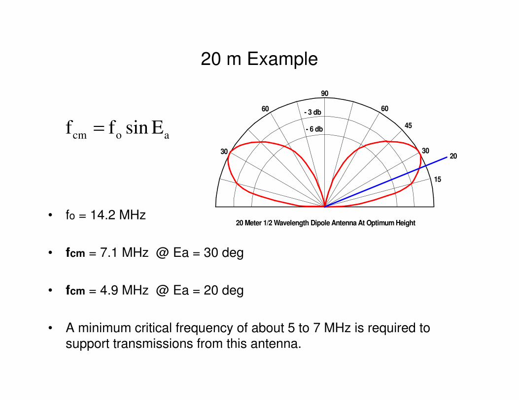
20 m Example
• fo = 14.2 MHz
• fcm = 7.1 MHz @ Ea = 30 deg
• fcm = 4.9 MHz @ Ea = 20 deg
• A minimum critical frequency of about 5 to 7 MHz is required to support transmissions from this antenna.
cm o af f sin E=
- 3 db
90
3030
60 60
- 6 db
20 Meter 1/2 Wavelength Dipole Antenna At Optimum Height
20
15
45
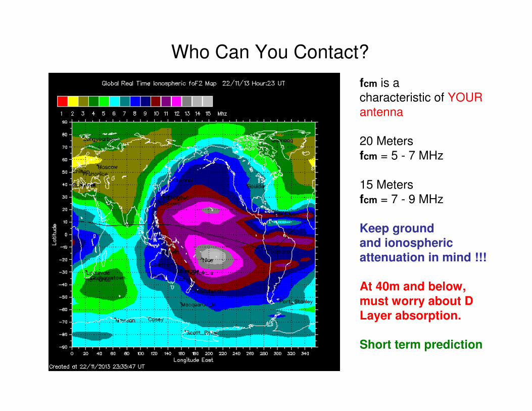
Who Can You Contact?
fcm is a
characteristic of YOUR
antenna
20 Meters
fcm = 5 - 7 MHz
15 Meters
fcm = 7 - 9 MHz
Keep ground and ionosphericattenuation in mind !!!
At 40m and below,
must worry about D Layer absorption.
Short term prediction

15 Meter Band Conditions
15 Meters Open15 Meters Open15 Meters Closed15 Meters Closed

Lowest Usable Frequency (LUF) Is:
• The lowest frequency radio signal
• Capable of propagating through the ionosphere
• From one specific radio station to an other
0
5
10
15
Fre
qu
ency
(M
Hz)
6 12 18 24Time (Hours)
MaximumUsableFrequency
Lowest Usable Frequency
UsableFrequency Window
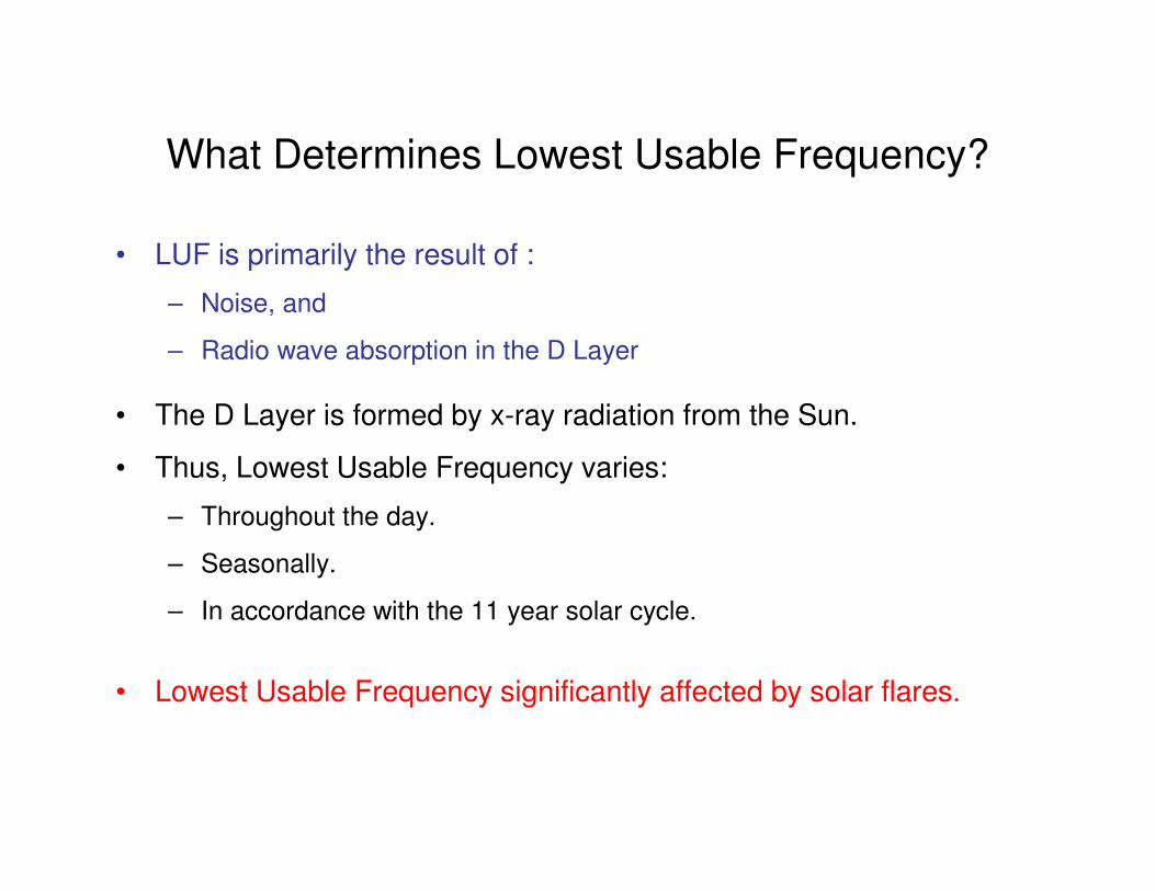
What Determines Lowest Usable Frequency?
• LUF is primarily the result of :
– Noise, and
– Radio wave absorption in the D Layer
• The D Layer is formed by x-ray radiation from the Sun.
• Thus, Lowest Usable Frequency varies:
– Throughout the day.
– Seasonally.
– In accordance with the 11 year solar cycle.
• Lowest Usable Frequency significantly affected by solar flares.
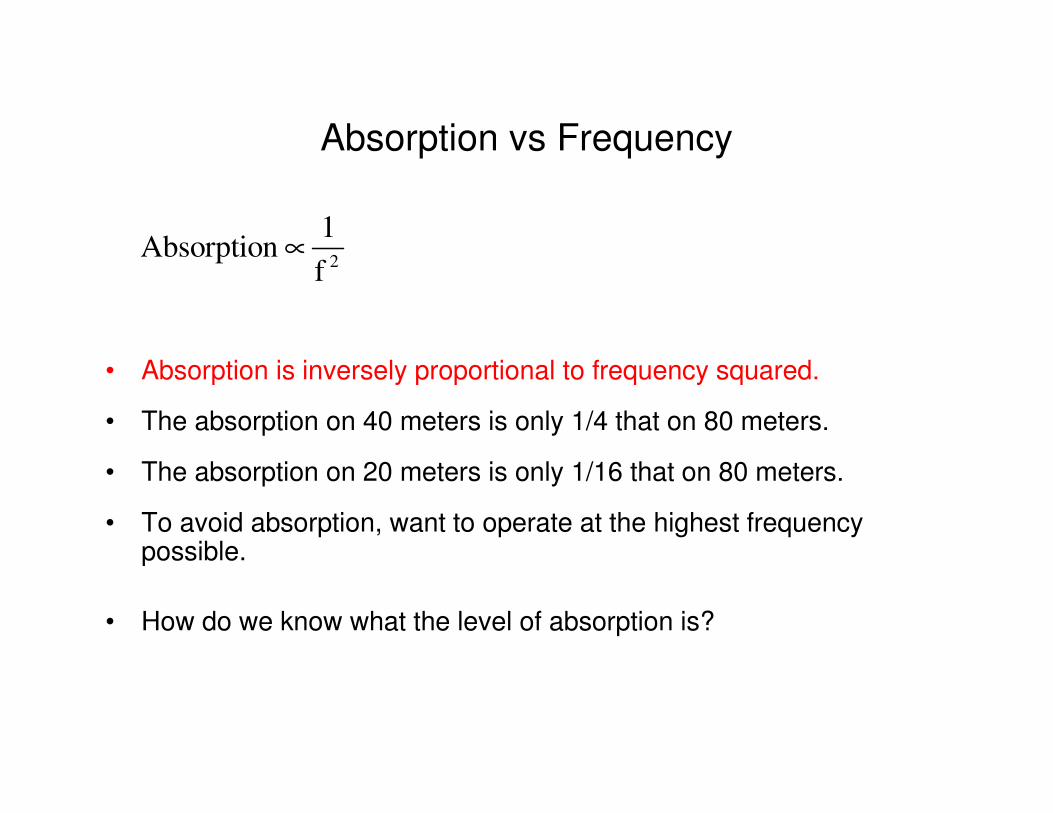
Absorption vs Frequency
• Absorption is inversely proportional to frequency squared.
• The absorption on 40 meters is only 1/4 that on 80 meters.
• The absorption on 20 meters is only 1/16 that on 80 meters.
• To avoid absorption, want to operate at the highest frequency possible.
• How do we know what the level of absorption is?
2
1Absorption
f∝

X-ray Flux a Good Measure of Absorption Levels
http://www.solarham.net/
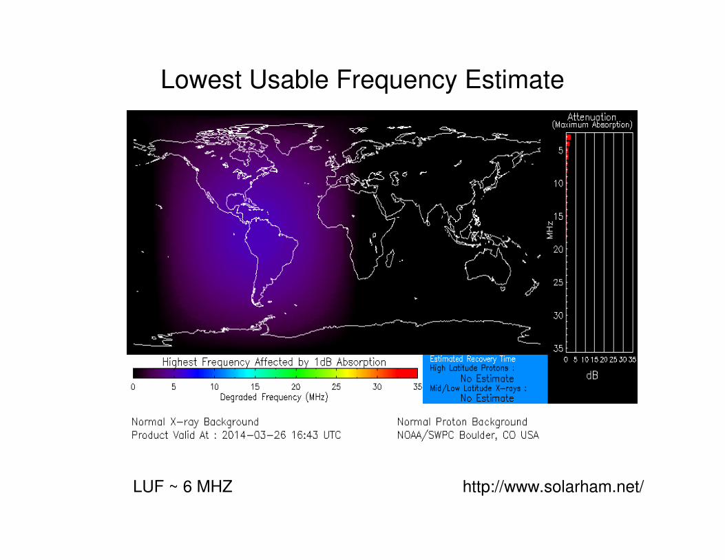
Lowest Usable Frequency Estimate
http://www.solarham.net/LUF ~ 6 MHZ

A Solar Flare Can Cause a Radio Blackout
0
5
10
15F
req
uen
cy (
MH
z)
6 12 18 24Time (Hours)
MaximumUsableFrequency
Lowest Usable Frequency
UsableFrequency Window
UsableFrequency Window
SolarFlare
Radio Blackout
What does a large flare look like at radio frequencies?

Flare Cause Large Increase In X-ray Flux

X-ray Flux Greatly Increase D Layer Absorption
LUF ~ 20 MHz http://www.solarham.net/

Statistical Forms of MUF
• MUF Median Value for the month
• Upper Decile
• Lower Decile
• MOF = Maximum Observed Frequency
• OWF = Optimum Working Frequency
• FOT = Frequency of Optimum Transmission
• Boulder MUF
– Predicted MUF from Boulder Colorado,
– For very low angle transmission, hop distance > 3000 miles
– Not likely to achieve these results using your antenna!
– Provides an upper bound on what ham bands may be open.

HF Radio is a LOT of FUN !